EP3824919A1 - Medical fluid therapy machine including pneumatic pump box and accumulators therefore - Google Patents
Medical fluid therapy machine including pneumatic pump box and accumulators therefore Download PDFInfo
- Publication number
- EP3824919A1 EP3824919A1 EP20213906.9A EP20213906A EP3824919A1 EP 3824919 A1 EP3824919 A1 EP 3824919A1 EP 20213906 A EP20213906 A EP 20213906A EP 3824919 A1 EP3824919 A1 EP 3824919A1
- Authority
- EP
- European Patent Office
- Prior art keywords
- medical fluid
- valve
- pneumatically actuated
- positive pressure
- pneumatically
- Prior art date
- Legal status (The legal status is an assumption and is not a legal conclusion. Google has not performed a legal analysis and makes no representation as to the accuracy of the status listed.)
- Granted
Links
Images



Classifications
-
- F—MECHANICAL ENGINEERING; LIGHTING; HEATING; WEAPONS; BLASTING
- F04—POSITIVE - DISPLACEMENT MACHINES FOR LIQUIDS; PUMPS FOR LIQUIDS OR ELASTIC FLUIDS
- F04B—POSITIVE-DISPLACEMENT MACHINES FOR LIQUIDS; PUMPS
- F04B43/00—Machines, pumps, or pumping installations having flexible working members
- F04B43/02—Machines, pumps, or pumping installations having flexible working members having plate-like flexible members, e.g. diaphragms
- F04B43/06—Pumps having fluid drive
-
- F—MECHANICAL ENGINEERING; LIGHTING; HEATING; WEAPONS; BLASTING
- F04—POSITIVE - DISPLACEMENT MACHINES FOR LIQUIDS; PUMPS FOR LIQUIDS OR ELASTIC FLUIDS
- F04B—POSITIVE-DISPLACEMENT MACHINES FOR LIQUIDS; PUMPS
- F04B41/00—Pumping installations or systems specially adapted for elastic fluids
- F04B41/06—Combinations of two or more pumps
-
- A—HUMAN NECESSITIES
- A61—MEDICAL OR VETERINARY SCIENCE; HYGIENE
- A61M—DEVICES FOR INTRODUCING MEDIA INTO, OR ONTO, THE BODY; DEVICES FOR TRANSDUCING BODY MEDIA OR FOR TAKING MEDIA FROM THE BODY; DEVICES FOR PRODUCING OR ENDING SLEEP OR STUPOR
- A61M1/00—Suction or pumping devices for medical purposes; Devices for carrying-off, for treatment of, or for carrying-over, body-liquids; Drainage systems
- A61M1/14—Dialysis systems; Artificial kidneys; Blood oxygenators ; Reciprocating systems for treatment of body fluids, e.g. single needle systems for hemofiltration or pheresis
-
- A—HUMAN NECESSITIES
- A61—MEDICAL OR VETERINARY SCIENCE; HYGIENE
- A61M—DEVICES FOR INTRODUCING MEDIA INTO, OR ONTO, THE BODY; DEVICES FOR TRANSDUCING BODY MEDIA OR FOR TAKING MEDIA FROM THE BODY; DEVICES FOR PRODUCING OR ENDING SLEEP OR STUPOR
- A61M1/00—Suction or pumping devices for medical purposes; Devices for carrying-off, for treatment of, or for carrying-over, body-liquids; Drainage systems
- A61M1/14—Dialysis systems; Artificial kidneys; Blood oxygenators ; Reciprocating systems for treatment of body fluids, e.g. single needle systems for hemofiltration or pheresis
- A61M1/16—Dialysis systems; Artificial kidneys; Blood oxygenators ; Reciprocating systems for treatment of body fluids, e.g. single needle systems for hemofiltration or pheresis with membranes
- A61M1/26—Dialysis systems; Artificial kidneys; Blood oxygenators ; Reciprocating systems for treatment of body fluids, e.g. single needle systems for hemofiltration or pheresis with membranes and internal elements which are moving
- A61M1/267—Dialysis systems; Artificial kidneys; Blood oxygenators ; Reciprocating systems for treatment of body fluids, e.g. single needle systems for hemofiltration or pheresis with membranes and internal elements which are moving used for pumping
-
- A—HUMAN NECESSITIES
- A61—MEDICAL OR VETERINARY SCIENCE; HYGIENE
- A61M—DEVICES FOR INTRODUCING MEDIA INTO, OR ONTO, THE BODY; DEVICES FOR TRANSDUCING BODY MEDIA OR FOR TAKING MEDIA FROM THE BODY; DEVICES FOR PRODUCING OR ENDING SLEEP OR STUPOR
- A61M1/00—Suction or pumping devices for medical purposes; Devices for carrying-off, for treatment of, or for carrying-over, body-liquids; Drainage systems
- A61M1/14—Dialysis systems; Artificial kidneys; Blood oxygenators ; Reciprocating systems for treatment of body fluids, e.g. single needle systems for hemofiltration or pheresis
- A61M1/28—Peritoneal dialysis ; Other peritoneal treatment, e.g. oxygenation
-
- A—HUMAN NECESSITIES
- A61—MEDICAL OR VETERINARY SCIENCE; HYGIENE
- A61M—DEVICES FOR INTRODUCING MEDIA INTO, OR ONTO, THE BODY; DEVICES FOR TRANSDUCING BODY MEDIA OR FOR TAKING MEDIA FROM THE BODY; DEVICES FOR PRODUCING OR ENDING SLEEP OR STUPOR
- A61M1/00—Suction or pumping devices for medical purposes; Devices for carrying-off, for treatment of, or for carrying-over, body-liquids; Drainage systems
- A61M1/34—Filtering material out of the blood by passing it through a membrane, i.e. hemofiltration or diafiltration
-
- A—HUMAN NECESSITIES
- A61—MEDICAL OR VETERINARY SCIENCE; HYGIENE
- A61M—DEVICES FOR INTRODUCING MEDIA INTO, OR ONTO, THE BODY; DEVICES FOR TRANSDUCING BODY MEDIA OR FOR TAKING MEDIA FROM THE BODY; DEVICES FOR PRODUCING OR ENDING SLEEP OR STUPOR
- A61M1/00—Suction or pumping devices for medical purposes; Devices for carrying-off, for treatment of, or for carrying-over, body-liquids; Drainage systems
- A61M1/34—Filtering material out of the blood by passing it through a membrane, i.e. hemofiltration or diafiltration
- A61M1/3413—Diafiltration
-
- A—HUMAN NECESSITIES
- A61—MEDICAL OR VETERINARY SCIENCE; HYGIENE
- A61M—DEVICES FOR INTRODUCING MEDIA INTO, OR ONTO, THE BODY; DEVICES FOR TRANSDUCING BODY MEDIA OR FOR TAKING MEDIA FROM THE BODY; DEVICES FOR PRODUCING OR ENDING SLEEP OR STUPOR
- A61M1/00—Suction or pumping devices for medical purposes; Devices for carrying-off, for treatment of, or for carrying-over, body-liquids; Drainage systems
- A61M1/34—Filtering material out of the blood by passing it through a membrane, i.e. hemofiltration or diafiltration
- A61M1/3496—Plasmapheresis; Leucopheresis; Lymphopheresis
-
- A—HUMAN NECESSITIES
- A61—MEDICAL OR VETERINARY SCIENCE; HYGIENE
- A61M—DEVICES FOR INTRODUCING MEDIA INTO, OR ONTO, THE BODY; DEVICES FOR TRANSDUCING BODY MEDIA OR FOR TAKING MEDIA FROM THE BODY; DEVICES FOR PRODUCING OR ENDING SLEEP OR STUPOR
- A61M39/00—Tubes, tube connectors, tube couplings, valves, access sites or the like, specially adapted for medical use
- A61M39/22—Valves or arrangement of valves
-
- F—MECHANICAL ENGINEERING; LIGHTING; HEATING; WEAPONS; BLASTING
- F04—POSITIVE - DISPLACEMENT MACHINES FOR LIQUIDS; PUMPS FOR LIQUIDS OR ELASTIC FLUIDS
- F04B—POSITIVE-DISPLACEMENT MACHINES FOR LIQUIDS; PUMPS
- F04B23/00—Pumping installations or systems
- F04B23/02—Pumping installations or systems having reservoirs
-
- F—MECHANICAL ENGINEERING; LIGHTING; HEATING; WEAPONS; BLASTING
- F04—POSITIVE - DISPLACEMENT MACHINES FOR LIQUIDS; PUMPS FOR LIQUIDS OR ELASTIC FLUIDS
- F04B—POSITIVE-DISPLACEMENT MACHINES FOR LIQUIDS; PUMPS
- F04B23/00—Pumping installations or systems
- F04B23/04—Combinations of two or more pumps
- F04B23/08—Combinations of two or more pumps the pumps being of different types
-
- F—MECHANICAL ENGINEERING; LIGHTING; HEATING; WEAPONS; BLASTING
- F04—POSITIVE - DISPLACEMENT MACHINES FOR LIQUIDS; PUMPS FOR LIQUIDS OR ELASTIC FLUIDS
- F04B—POSITIVE-DISPLACEMENT MACHINES FOR LIQUIDS; PUMPS
- F04B37/00—Pumps having pertinent characteristics not provided for in, or of interest apart from, groups F04B25/00 - F04B35/00
- F04B37/10—Pumps having pertinent characteristics not provided for in, or of interest apart from, groups F04B25/00 - F04B35/00 for special use
- F04B37/12—Pumps having pertinent characteristics not provided for in, or of interest apart from, groups F04B25/00 - F04B35/00 for special use to obtain high pressure
-
- F—MECHANICAL ENGINEERING; LIGHTING; HEATING; WEAPONS; BLASTING
- F04—POSITIVE - DISPLACEMENT MACHINES FOR LIQUIDS; PUMPS FOR LIQUIDS OR ELASTIC FLUIDS
- F04B—POSITIVE-DISPLACEMENT MACHINES FOR LIQUIDS; PUMPS
- F04B37/00—Pumps having pertinent characteristics not provided for in, or of interest apart from, groups F04B25/00 - F04B35/00
- F04B37/10—Pumps having pertinent characteristics not provided for in, or of interest apart from, groups F04B25/00 - F04B35/00 for special use
- F04B37/14—Pumps having pertinent characteristics not provided for in, or of interest apart from, groups F04B25/00 - F04B35/00 for special use to obtain high vacuum
-
- F—MECHANICAL ENGINEERING; LIGHTING; HEATING; WEAPONS; BLASTING
- F04—POSITIVE - DISPLACEMENT MACHINES FOR LIQUIDS; PUMPS FOR LIQUIDS OR ELASTIC FLUIDS
- F04B—POSITIVE-DISPLACEMENT MACHINES FOR LIQUIDS; PUMPS
- F04B37/00—Pumps having pertinent characteristics not provided for in, or of interest apart from, groups F04B25/00 - F04B35/00
- F04B37/10—Pumps having pertinent characteristics not provided for in, or of interest apart from, groups F04B25/00 - F04B35/00 for special use
- F04B37/18—Pumps having pertinent characteristics not provided for in, or of interest apart from, groups F04B25/00 - F04B35/00 for special use for specific elastic fluids
-
- F—MECHANICAL ENGINEERING; LIGHTING; HEATING; WEAPONS; BLASTING
- F04—POSITIVE - DISPLACEMENT MACHINES FOR LIQUIDS; PUMPS FOR LIQUIDS OR ELASTIC FLUIDS
- F04B—POSITIVE-DISPLACEMENT MACHINES FOR LIQUIDS; PUMPS
- F04B39/00—Component parts, details, or accessories, of pumps or pumping systems specially adapted for elastic fluids, not otherwise provided for in, or of interest apart from, groups F04B25/00 - F04B37/00
- F04B39/06—Cooling; Heating; Prevention of freezing
- F04B39/066—Cooling by ventilation
-
- F—MECHANICAL ENGINEERING; LIGHTING; HEATING; WEAPONS; BLASTING
- F04—POSITIVE - DISPLACEMENT MACHINES FOR LIQUIDS; PUMPS FOR LIQUIDS OR ELASTIC FLUIDS
- F04B—POSITIVE-DISPLACEMENT MACHINES FOR LIQUIDS; PUMPS
- F04B39/00—Component parts, details, or accessories, of pumps or pumping systems specially adapted for elastic fluids, not otherwise provided for in, or of interest apart from, groups F04B25/00 - F04B37/00
- F04B39/10—Adaptations or arrangements of distribution members
-
- F—MECHANICAL ENGINEERING; LIGHTING; HEATING; WEAPONS; BLASTING
- F04—POSITIVE - DISPLACEMENT MACHINES FOR LIQUIDS; PUMPS FOR LIQUIDS OR ELASTIC FLUIDS
- F04B—POSITIVE-DISPLACEMENT MACHINES FOR LIQUIDS; PUMPS
- F04B39/00—Component parts, details, or accessories, of pumps or pumping systems specially adapted for elastic fluids, not otherwise provided for in, or of interest apart from, groups F04B25/00 - F04B37/00
- F04B39/12—Casings; Cylinders; Cylinder heads; Fluid connections
- F04B39/121—Casings
-
- F—MECHANICAL ENGINEERING; LIGHTING; HEATING; WEAPONS; BLASTING
- F04—POSITIVE - DISPLACEMENT MACHINES FOR LIQUIDS; PUMPS FOR LIQUIDS OR ELASTIC FLUIDS
- F04B—POSITIVE-DISPLACEMENT MACHINES FOR LIQUIDS; PUMPS
- F04B39/00—Component parts, details, or accessories, of pumps or pumping systems specially adapted for elastic fluids, not otherwise provided for in, or of interest apart from, groups F04B25/00 - F04B37/00
- F04B39/16—Filtration; Moisture separation
-
- F—MECHANICAL ENGINEERING; LIGHTING; HEATING; WEAPONS; BLASTING
- F04—POSITIVE - DISPLACEMENT MACHINES FOR LIQUIDS; PUMPS FOR LIQUIDS OR ELASTIC FLUIDS
- F04B—POSITIVE-DISPLACEMENT MACHINES FOR LIQUIDS; PUMPS
- F04B41/00—Pumping installations or systems specially adapted for elastic fluids
- F04B41/02—Pumping installations or systems specially adapted for elastic fluids having reservoirs
-
- F—MECHANICAL ENGINEERING; LIGHTING; HEATING; WEAPONS; BLASTING
- F04—POSITIVE - DISPLACEMENT MACHINES FOR LIQUIDS; PUMPS FOR LIQUIDS OR ELASTIC FLUIDS
- F04B—POSITIVE-DISPLACEMENT MACHINES FOR LIQUIDS; PUMPS
- F04B53/00—Component parts, details or accessories not provided for in, or of interest apart from, groups F04B1/00 - F04B23/00 or F04B39/00 - F04B47/00
- F04B53/06—Venting
-
- F—MECHANICAL ENGINEERING; LIGHTING; HEATING; WEAPONS; BLASTING
- F15—FLUID-PRESSURE ACTUATORS; HYDRAULICS OR PNEUMATICS IN GENERAL
- F15B—SYSTEMS ACTING BY MEANS OF FLUIDS IN GENERAL; FLUID-PRESSURE ACTUATORS, e.g. SERVOMOTORS; DETAILS OF FLUID-PRESSURE SYSTEMS, NOT OTHERWISE PROVIDED FOR
- F15B1/00—Installations or systems with accumulators; Supply reservoir or sump assemblies
- F15B1/02—Installations or systems with accumulators
- F15B1/04—Accumulators
-
- A—HUMAN NECESSITIES
- A61—MEDICAL OR VETERINARY SCIENCE; HYGIENE
- A61M—DEVICES FOR INTRODUCING MEDIA INTO, OR ONTO, THE BODY; DEVICES FOR TRANSDUCING BODY MEDIA OR FOR TAKING MEDIA FROM THE BODY; DEVICES FOR PRODUCING OR ENDING SLEEP OR STUPOR
- A61M2205/00—General characteristics of the apparatus
- A61M2205/07—General characteristics of the apparatus having air pumping means
-
- F—MECHANICAL ENGINEERING; LIGHTING; HEATING; WEAPONS; BLASTING
- F04—POSITIVE - DISPLACEMENT MACHINES FOR LIQUIDS; PUMPS FOR LIQUIDS OR ELASTIC FLUIDS
- F04B—POSITIVE-DISPLACEMENT MACHINES FOR LIQUIDS; PUMPS
- F04B43/00—Machines, pumps, or pumping installations having flexible working members
- F04B43/02—Machines, pumps, or pumping installations having flexible working members having plate-like flexible members, e.g. diaphragms
- F04B43/06—Pumps having fluid drive
- F04B43/073—Pumps having fluid drive the actuating fluid being controlled by at least one valve
-
- F—MECHANICAL ENGINEERING; LIGHTING; HEATING; WEAPONS; BLASTING
- F04—POSITIVE - DISPLACEMENT MACHINES FOR LIQUIDS; PUMPS FOR LIQUIDS OR ELASTIC FLUIDS
- F04B—POSITIVE-DISPLACEMENT MACHINES FOR LIQUIDS; PUMPS
- F04B53/00—Component parts, details or accessories not provided for in, or of interest apart from, groups F04B1/00 - F04B23/00 or F04B39/00 - F04B47/00
- F04B53/10—Valves; Arrangement of valves
-
- F—MECHANICAL ENGINEERING; LIGHTING; HEATING; WEAPONS; BLASTING
- F04—POSITIVE - DISPLACEMENT MACHINES FOR LIQUIDS; PUMPS FOR LIQUIDS OR ELASTIC FLUIDS
- F04B—POSITIVE-DISPLACEMENT MACHINES FOR LIQUIDS; PUMPS
- F04B7/00—Piston machines or pumps characterised by having positively-driven valving
- F04B7/02—Piston machines or pumps characterised by having positively-driven valving the valving being fluid-actuated
- F04B7/0266—Piston machines or pumps characterised by having positively-driven valving the valving being fluid-actuated the inlet and discharge means being separate members
- F04B7/0275—Piston machines or pumps characterised by having positively-driven valving the valving being fluid-actuated the inlet and discharge means being separate members and being deformable, e.g. membranes
-
- F—MECHANICAL ENGINEERING; LIGHTING; HEATING; WEAPONS; BLASTING
- F04—POSITIVE - DISPLACEMENT MACHINES FOR LIQUIDS; PUMPS FOR LIQUIDS OR ELASTIC FLUIDS
- F04B—POSITIVE-DISPLACEMENT MACHINES FOR LIQUIDS; PUMPS
- F04B9/00—Piston machines or pumps characterised by the driving or driven means to or from their working members
- F04B9/08—Piston machines or pumps characterised by the driving or driven means to or from their working members the means being fluid
- F04B9/12—Piston machines or pumps characterised by the driving or driven means to or from their working members the means being fluid the fluid being elastic, e.g. steam or air
-
- F—MECHANICAL ENGINEERING; LIGHTING; HEATING; WEAPONS; BLASTING
- F04—POSITIVE - DISPLACEMENT MACHINES FOR LIQUIDS; PUMPS FOR LIQUIDS OR ELASTIC FLUIDS
- F04B—POSITIVE-DISPLACEMENT MACHINES FOR LIQUIDS; PUMPS
- F04B9/00—Piston machines or pumps characterised by the driving or driven means to or from their working members
- F04B9/08—Piston machines or pumps characterised by the driving or driven means to or from their working members the means being fluid
- F04B9/12—Piston machines or pumps characterised by the driving or driven means to or from their working members the means being fluid the fluid being elastic, e.g. steam or air
- F04B9/123—Piston machines or pumps characterised by the driving or driven means to or from their working members the means being fluid the fluid being elastic, e.g. steam or air having only one pumping chamber
-
- F—MECHANICAL ENGINEERING; LIGHTING; HEATING; WEAPONS; BLASTING
- F04—POSITIVE - DISPLACEMENT MACHINES FOR LIQUIDS; PUMPS FOR LIQUIDS OR ELASTIC FLUIDS
- F04B—POSITIVE-DISPLACEMENT MACHINES FOR LIQUIDS; PUMPS
- F04B9/00—Piston machines or pumps characterised by the driving or driven means to or from their working members
- F04B9/08—Piston machines or pumps characterised by the driving or driven means to or from their working members the means being fluid
- F04B9/12—Piston machines or pumps characterised by the driving or driven means to or from their working members the means being fluid the fluid being elastic, e.g. steam or air
- F04B9/123—Piston machines or pumps characterised by the driving or driven means to or from their working members the means being fluid the fluid being elastic, e.g. steam or air having only one pumping chamber
- F04B9/127—Piston machines or pumps characterised by the driving or driven means to or from their working members the means being fluid the fluid being elastic, e.g. steam or air having only one pumping chamber rectilinear movement of the pumping member in the working direction being obtained by a single-acting elastic-fluid motor, e.g. actuated in the other direction by gravity or a spring
- F04B9/1276—Piston machines or pumps characterised by the driving or driven means to or from their working members the means being fluid the fluid being elastic, e.g. steam or air having only one pumping chamber rectilinear movement of the pumping member in the working direction being obtained by a single-acting elastic-fluid motor, e.g. actuated in the other direction by gravity or a spring with fluid-actuated inlet or outlet valve
-
- F—MECHANICAL ENGINEERING; LIGHTING; HEATING; WEAPONS; BLASTING
- F15—FLUID-PRESSURE ACTUATORS; HYDRAULICS OR PNEUMATICS IN GENERAL
- F15B—SYSTEMS ACTING BY MEANS OF FLUIDS IN GENERAL; FLUID-PRESSURE ACTUATORS, e.g. SERVOMOTORS; DETAILS OF FLUID-PRESSURE SYSTEMS, NOT OTHERWISE PROVIDED FOR
- F15B2201/00—Accumulators
- F15B2201/30—Accumulator separating means
- F15B2201/315—Accumulator separating means having flexible separating means
- F15B2201/3152—Accumulator separating means having flexible separating means the flexible separating means being bladders
-
- F—MECHANICAL ENGINEERING; LIGHTING; HEATING; WEAPONS; BLASTING
- F15—FLUID-PRESSURE ACTUATORS; HYDRAULICS OR PNEUMATICS IN GENERAL
- F15B—SYSTEMS ACTING BY MEANS OF FLUIDS IN GENERAL; FLUID-PRESSURE ACTUATORS, e.g. SERVOMOTORS; DETAILS OF FLUID-PRESSURE SYSTEMS, NOT OTHERWISE PROVIDED FOR
- F15B2201/00—Accumulators
- F15B2201/30—Accumulator separating means
- F15B2201/315—Accumulator separating means having flexible separating means
- F15B2201/3156—Accumulator separating means having flexible separating means characterised by their attachment
-
- F—MECHANICAL ENGINEERING; LIGHTING; HEATING; WEAPONS; BLASTING
- F15—FLUID-PRESSURE ACTUATORS; HYDRAULICS OR PNEUMATICS IN GENERAL
- F15B—SYSTEMS ACTING BY MEANS OF FLUIDS IN GENERAL; FLUID-PRESSURE ACTUATORS, e.g. SERVOMOTORS; DETAILS OF FLUID-PRESSURE SYSTEMS, NOT OTHERWISE PROVIDED FOR
- F15B2201/00—Accumulators
- F15B2201/40—Constructional details of accumulators not otherwise provided for
-
- F—MECHANICAL ENGINEERING; LIGHTING; HEATING; WEAPONS; BLASTING
- F15—FLUID-PRESSURE ACTUATORS; HYDRAULICS OR PNEUMATICS IN GENERAL
- F15B—SYSTEMS ACTING BY MEANS OF FLUIDS IN GENERAL; FLUID-PRESSURE ACTUATORS, e.g. SERVOMOTORS; DETAILS OF FLUID-PRESSURE SYSTEMS, NOT OTHERWISE PROVIDED FOR
- F15B2201/00—Accumulators
- F15B2201/40—Constructional details of accumulators not otherwise provided for
- F15B2201/405—Housings
Definitions
- the present disclosure relates generally to devices, systems and methods for medical fluid delivery machines. More specifically, the present disclosure relates to medical fluid delivery machines, such as renal failure therapy machines, that employ pneumatic pumping.
- Renal failure produces several physiological derangements. It is no longer possible to balance water and minerals or to excrete daily metabolic load. Toxic end products of nitrogen metabolism (urea, creatinine, uric acid, and others) can accumulate in blood and tissue.
- urea urea, creatinine, uric acid, and others
- Kidney failure and reduced kidney function have been treated with dialysis. Dialysis removes waste, toxins and excess water from the body that normal functioning kidneys would otherwise remove. Dialysis treatment for replacement of kidney functions is critical to many people because the treatment is life saving.
- kidney failure therapy is Hemodialysis ("HD"), which in general uses diffusion to remove waste products from a patient's blood. A diffusive gradient occurs across the semi-permeable dialyzer between the blood and an electrolyte solution called dialysate or dialysis fluid to cause diffusion.
- HD Hemodialysis
- Hemofiltration is an alternative renal replacement therapy that relies on a convective transport of toxins from the patient's blood.
- HF is accomplished by adding substitution or replacement fluid to the extracorporeal circuit during treatment (typically ten to ninety liters of such fluid).
- substitution fluid and the fluid accumulated by the patient in between treatments is ultrafiltered over the course of the HF treatment, providing a convective transport mechanism that is particularly beneficial in removing middle and large molecules (in hemodialysis there is a small amount of waste removed along with the fluid gained between dialysis sessions, however, the solute drag from the removal of that ultrafiltrate is not enough to provide convective clearance).
- HDF Hemodiafiltration
- dialysis fluid flowing through a dialyzer similar to standard hemodialysis, to provide diffusive clearance.
- substitution solution is provided directly to the extracorporeal circuit, providing convective clearance.
- HHD home hemodialysis
- kidney failure therapy is peritoneal dialysis, which infuses a dialysis solution, also called dialysis fluid, into a patient's peritoneal cavity via a catheter.
- the dialysis fluid contacts the peritoneal membrane of the peritoneal cavity.
- Waste, toxins and excess water pass from the patient's bloodstream, through the peritoneal membrane and into the dialysis fluid due to diffusion and osmosis, i.e., an osmotic gradient occurs across the membrane.
- An osmotic agent in dialysis provides the osmotic gradient.
- the used or spent dialysis fluid is drained from the patient, removing waste, toxins and excess water from the patient. This cycle is repeated, e.g., multiple times.
- CAPD continuous ambulatory peritoneal dialysis
- APD automated peritoneal dialysis
- CFPD continuous flow peritoneal dialysis
- CAPD is a manual dialysis treatment.
- the patient manually connects an implanted catheter to a drain to allow used or spent dialysate fluid to drain from the peritoneal cavity.
- the patient then connects the catheter to a bag of fresh dialysis fluid to infuse fresh dialysis fluid through the catheter and into the patient.
- the patient disconnects the catheter from the fresh dialysis fluid bag and allows the dialysis fluid to dwell within the peritoneal cavity, wherein the transfer of waste, toxins and excess water takes place. After a dwell period, the patient repeats the manual dialysis procedure, for example, four times per day, each treatment lasting about an hour. Manual peritoneal dialysis requires a significant amount of time and effort from the patient, leaving ample room for improvement.
- APD Automated peritoneal dialysis
- CAPD Automated peritoneal dialysis
- APD machines perform the cycles automatically, typically while the patient sleeps.
- APD machines free patients from having to perform the treatment cycles manually and from having to transport supplies during the day.
- APD machines connect fluidly to an implanted catheter, to a source or bag of fresh dialysis fluid and to a fluid drain.
- APD machines pump fresh dialysis fluid from a dialysis fluid source, through the catheter and into the patient's peritoneal cavity.
- APD machines also allow for the dialysis fluid to dwell within the cavity and for the transfer of waste, toxins and excess water to take place.
- the source may include multiple sterile dialysis fluid solution bags.
- APD machines pump used or spent dialysate from the peritoneal cavity, though the catheter, and to the drain. As with the manual process, several drain, fill and dwell cycles occur during dialysis. A "last fill” occurs at the end of APD and remains in the peritoneal cavity of the patient until the next treatment.
- Pneumatic pumping typically involves the application of positive and/or negative air pressure to a pumping membrane or diaphragm.
- Positive pressure may be provided via a compressor feeding a positive pressure tank or accumulator.
- Negative pressure may be provided via a vacuum pump feeding a negative pressure tank or accumulator. Attempts may be made to remove water from the positive pressure prior to the air being fed to the positive pressure tank accumulator. Water present in positive pressure air can lead to corrosion within the solenoid valves and elsewhere.
- the components described above may generate heat or may operate more effectively in a non-heated environment. An improved coordination of such components is needed accordingly.
- the positive pressure accumulator is effective only until its pressure reaches that needed to drive a certain application.
- a pressure regulator may be present between the positive pressure accumulator and the application, e.g., a fluid valve. If the regulator is set to deliver 5 psig to close the valve, for example, then the accumulator cannot deliver the pressure necessary to close the valve once its pressure falls below 5 psig.
- the positive and negative accumulators deliver positive and negative pressure, respectively, for as long as possible. An additional need exists accordingly to extend the useful life of the pneumatic pressure accumulators.
- the examples described herein disclose pump box devices, systems and methods therefore applicable, for example, to fluid delivery for: plasmapherisis, hemodialysis (“HD”), hemofiltration (“HF”) hemodiafiltration (“HDF”), and continuous renal replacement therapy (“CRRT”) treatments.
- the pump box devices, and systems and methods therefore described herein are also applicable to peritoneal dialysis (“PD”) and to intravenous drug delivery. These modalities may be referred to collectively or generally individually as medical fluid delivery.
- each of the devices, systems and methods described herein may be used with clinical or home-based machines.
- the systems may be employed in in-center HD, HF or HDF machines, which run throughout the day.
- the systems may be used with home HD, HF or HDF machines, which are operated at the patient's convenience.
- One such home system is described in U.S. Patent No. 8,029,454 ("the '454 Patent”), issued October 4, 2011, entitled “High Convection Home Hemodialysis/Hemofiltration And Sorbent System", filed November 4, 2004, assigned to the assignee of the present application.
- Another such home system is described in U.S. Patent No. 8,393,690 (“the '690 Patent”), issued March 12, 2013, entitled “Enclosure for a Portable Hemodialysis System", filed August 27, 2008. The entire contents of each of the above references are incorporated herein by reference and relied upon.
- a medical fluid delivery machine in an embodiment, includes a medical fluid delivery chassis.
- the medical fluid delivery chassis houses components needed to deliver medical fluid, such as one or more pump, plural valves, a heater if needed, online medical fluid generation equipment if needed and desired, plural sensors, such as any one, or more, or all of pressure sensors, conductivity sensors, temperature sensors, air detectors, blood leak detectors, and the like, a user interface, and a control unit, which may employ one or more processor and memory to control the above-described equipment.
- Air as used herein means air as it exists naturally, which is made up of individual gases such as nitrogen, oxygen, argon, and carbon dioxide. "Air” may also include a desired modified atmosphere, such as a larger percentage of, or a pure gas, such nitrogen or carbon dioxide.
- the term "pneumatic” also refers to naturally occurring air and/or any type of modified atmosphere.
- the pneumatic pump box may house components, such as a vacuum pump for supplying negative air pressure, a compressor for supplying positive air pressure, a dryer for removing water from the positive pressure air outputted from the compressor prior to storage in the accumulator, and positive and negative accumulators for storing positive and negative air pressure, respectvely.
- the pneumatic pump box may be attached removeably to the medical fluid delivery chassis. If the medical fluid delivery machine is to be operated while the patient is sleeping, for example, or if the patient desires a quiet environment for whatever reason, it may be desirable for the patient to remove the pneumatic pump box and store it in a closet or other remote location to dampen its noise.
- the removable pneumatic pump box is connected pneumatically to the medical fluid delivery chassis via one or more positive and negative pressure lines and may receive electrical power via its own electrical cord or via an electrical power feed from the chassis.
- the pneumatic pump box's vacuum pump is typically the hottest point in the box during operation.
- the dryer in an embodiment cools air from the compressor to condense water from the compressed air, so that the water may be removed before being delivered into the positive pressure accumulator. Removing water from the compressed air is important because water in the compressed air volume may cause system failure due to corrosion.
- the pneumatic box of the present disclosure accordingly places the vacuum pump at the top of the pneumatic pump box. Here, heat rises from the vacuum pump to the top of the box, such that its impact on the other components in the box is minimized. It is further contemplated to place a small, inexpensive fan directly in the top of the box directly above the dryer, which is oriented to pull the heated air out of the box. Intake vents for the fan may be provided in the pump box, e.g., just below the vacuum pump.
- the goals for locating the remainder of the equipment are two-fold, namely, (i) to locate the dryer as far away from the vacuum pump as possible to prevent heat generated from the vacuum pump from heating the dryer, and (ii) to reduce and simplify the routing of tubing between the pneumatic pump box as much as possible.
- either the compressor or the dryer may be located at the bottom of the box. Locating the compressor at the bottom of the box, the dryer above the compressor and the accumulators above the dryer optimizes the routing of tubing and other air connections, which run from the compressor to the dryer, and from the dryer to the positive pressure accumulator. On the other hand, locating the dryer at the bottom of the box, the compressor above the dryer, and the accumulators above the compressor, spaces the dryer (e.g., chilling device) as far away as possible from the heat-producing vacuum pump.
- the dryer e.g., chilling device
- the pneumatic pump box includes two accumulators, namely, a positive pressure accumulator and a negative pressure accumulator. It is possible that the pneumatic pump and valve control may use different pressure levels at different locations within the medical fluid delivery machine.
- a pneumatic pump may include a pump chamber associated with its own inlet and outlet valve chambers, wherein the pressure applied to the valve chambers is greater than the pressure applied to the pump chamber, so that operation of the pump chamber does not affect a desired valve state.
- multiple accumulators may be provided to store multiple positive and/or negative pressures. In one preferred embodiment, however, a single positive pressure accumulator and a single negative pressure accumulator are provided to feed multiple pneumatic regulators that set the different desired positive and/or negative pneumatic operating pressures.
- the pneumatic regulators may include static regulators that set a desired positive or negative pneumatic pressure, for example, to feed multiple on/off or binary applications.
- the pneumatic regulators may alternatively or additionally include a variable diameter orifice, e.g., as a variable valve or vari-valve.
- Components, such as the pneumatic regulators, binary pneumatic valves and the vari-valves are placed in an embodiment on a manifold that is located inside the medical fluid delivery chassis, so that single positive and negative pressure lines from the pneumatic pump box to the chassis can feed each of the components of the manifold.
- an elastic accumulator bladder inside of an outer, rigid positive pressure accumulator housing, which limits the size to which the bladder can expand, and also defines the shape of the bladder when expanded to fill the volume of the accumulator housing fully.
- the bladder is formed to require a certain positive pressure for inflation, namely, the bladder inflation pressure.
- the rigid outer chamber is vented in an embodiment, so that air between the bladder and rigid outer chamber can be displaced to atmosphere when the bladder is inflated.
- the accumulator bladder contracts and continues to deliver positive pressure air volume at the bladder inflation pressure until the accumulator bladder is fully contracted. During contraction, atmospheric air is drawn into the rigid outer container outside of the bladder via the vent. The overall volume of air delivered is greater than that possible with a rigid accumulator alone due to the force applied by the bladder elastomer to the internal bladder air volume.
- the accumulator is charged via a compressor to a set pressure, which is above a desired operating pressure.
- the desired operating pressure is achieved by using a regulator to set an accurate downstream pneumatic pressure. It is contemplated to construct the bladder to make the bladder inflation pressure just slightly above the desired operating pressure. In this manner, most all of the pressure delta between the set charging pressure and the desired operation pressure is consumed prior to the contraction of the bladder.
- the fluid valves are closed under positive pressure and opened by venting the positive pressure to atmosphere.
- a first electrically operated solenoid valve may be provided to allow or not allow positive pressure to flow or not flow to the fluid valve.
- a second electrically operated solenoid valve is provided to allow or not allow the positive pressure to vent to atmosphere.
- the first electrically operated solenoid valve is opened, while the second electrically operated solenoid valve is closed, which allows the fluid valve to see positive air pressure, which is not vented.
- the first electrically operated solenoid valve is closed, while the second electrically operated solenoid valve is opened, which shuts off positive pressure to the fluid valve and vents the existing positive pressure at the fluid valve to atmosphere, enabling the fluid valve to open.
- the fluid valve may open due to the force of fluid pressure on the fluid side of a valve diaphragm and/or the valve diaphragm may be preformed or predomed and be placed or positioned so as to be biased fluid open when not under positive pressure. It should be appreciated then that in one embodiment, while the pump chamber requires positive and negative pneumatic pressure, the corresponding valve chambers only require positive pneumatic pressure. The life of the fluid pump including inlet and outlet valves may therefore be extended by extending the life of the positive pressure via the accumulator bladder of the present disclosure without a corresponding extension of the life of the negative pressure source.
- a reverse accumulator structure is applied to the negative pressure accumulator.
- an elastic bladder is preformed to have the same shape as for the positive pressure accumulator. The difference is that the vacuum is applied to the vent port of the positive chamber to draw a vacuum on the air between the bladder and the rigid outer chamber of the negative pressure accumulator.
- the vent port for the negative pressure accumulator is the port leading to the inside of the bladder (which is the supply port for the positive accumulator).
- the negative pressure bladder is thickened as necessary to fully inflate under a more negative pressure than the desired regulated negative pressure, so that the bladder can provide the negative pressure to drive the negative regulator until the bladder is fully contracted.
- the bladder and the ridged outer housing accumulator are configured so that a full vacuum can be drawn before the negative pressure bladder expands to block or fully block the vacuum port provided by the housing, and/or (ii) the vacuum port can be angled on the inside of the rigid housing so that it is difficult for the bladder to block.
- the negative pressure accumulator begins to contract after the negative pressure in the vacuum line starts to become less negative than the required negative bladder inflation pressure (not enough negative pressure to keep the bladder fully expanded.
- the negative pressure remains at the negative pressure inflation pressure until the bladder is fully contracted, leaving the rigid outer chamber virtually fully charged with negative pressure to drive the negative regulator.
- the outer, rigid accumulator housing is vented to atmosphere so that the bladder can inflate and contract freely under positive or negative pressure.
- the dialysis machine may provide battery power to power the pneumatic valves, enabling pneumatic pressure to be applied to the fluid valves and pump chambers.
- the bladders increase the volume of positive and negative pressure air that can be extracted from the accumulators to maintain the desired working pressure for a longer period, allowing more blood to be pushed back to the patient.
- the additional working pressure may be used to lower the leak tightness requirements of the on-off binary and vari-valves, making the overall machine more robust.
- a medical fluid delivery machine includes: a medical fluid pump including a pneumatically actuated pump chamber and first and second pneumatically actuated medical fluid valve chambers located respectively upstream and downstream of the pneumatically actuated pump chamber; a compresssor for creating positive pressure air; and an accumulator storing the positive pressure air for delivery to at least one of the pneumatically actuated pump chamber, the first pneumatically actuated medical fluid valve chamber, or the second pneumatically actuated medical fluid valve chamber, the accumulator holding an elastic bladder that inflates under positive pressure air from the compressor, creating additional positive pressure that increases the amount of positive pressure air that the accumulator can provide.
- the accumulator includes an outer rigid housing holding the elastic bladder, and wherein the bladder is held in a sealed relationship with the outer rigid housing.
- the outer rigid housing is vented.
- the medical fluid delivery machine includes a connector forming the sealed relationship between the bladder and the outer rigid housing.
- the connector includes a sealing end configured to seal to the open end of the bladder and a tube connecting end configured to seal to a pneumatic tube extending from the accumulator.
- the outer rigid housing is countoured to enable the elastic bladder when expanded to conform at least substantially completely to an inner shape of the outer rigid housing.
- the bladder initially has a thin tube shape and expands to conform at least substantially completely to the inner shape of the outer rigid housing.
- the medical fluid delivery machine includes a pneumatic regulator located between the accumulator and the at least one of the pneumatically actuated pump chamber, the first pneumatically actuated medical fluid valve chamber, or the second pneumatically actuated medical fluid valve chamber, the pneumatic regulator setting a desired output pressure for the positive pressure air, the bladder enabling the additional amount of the positive pressure air to be provided to the pneumatic regulator.
- the bladder is structured so that a pressure needed to inflate the bladder is slightly greater than the desired output pressure.
- At least one of the first and second pneumatically actuated medical fluid valve chambers is closed via positive pressure and opened via venting to atmosphere.
- a medical fluid delivery machine includes: a medical fluid pump including a pneumatically actuated pump chamber and first and second pneumatically actuated medical fluid valve chambers located respectively upstream and downstream of the pneumatically actuated pump chamber; a vacuum pump for creating negative pressure; and an accumulator storing the negative pressure for operation with at least one of the pneumatically actuated pump chamber, the first pneumatically actuated medical fluid valve chamber or the second pneumatically actuated medical fluid valve chamber, the accumulator holding an elastic bladder that inflates under negative pressure from the vacuum pump applied to an outside of the elastic bladder, creating additional negative pressure that increases the amount of negative pressure that the accumulator can provide.
- the accumulator includes an outer rigid housing holding the elastic bladder, and wherein the bladder is held in a sealed relationship with the outer rigid hosuing.
- negative pressure from the vacuum pump is applied to the accumulator via a port provided on the outer rigid housing located outside of the elastic bladder.
- At least one of (i) the outer rigid housing is countoured to enable the elastic bladder to fully inflate prior to blocking the port of the outer rigid housing or (ii) the outer rigid housing is countoured to enable the elastic bladder when inflated to conform at least substantially completely to an inner shape of the outer rigid housing.
- the medical fluid delivery machine includes a pneumatic regulator located between the accumulator and the at least one of the pneumatically actuated pump chamber, the first pneumatically actuated medical fluid valve chamber, or the second pneumatically actuated medical fluid valve chamber, the pneumatic regulator setting a desired negative operating pressure, the bladder increasing the amount of negative pressure greater than the desired negative operating pressure for supply to the regulator.
- the inside of the bladder is vented to atmosphere.
- the bladder is preformed to have a thin tube shape that is thickend so that the bladder is configured to inflate at a negative pressure at least approximately equal to a desired negative pressure for the accumulator when fully charged.
- a medical fluid delivery machine includes: a compresssor for creating positive pressure air; a vacuum pump for creating negative pressure; a first accumulator storing the positive pressure air for delivery within the medical fluid machine, the first accumulator holding a first elastic bladder that inflates under positive pressure air from the compressor applied to an inside of the bladder, increasing the amount of positive pressure air that the accumulator can provide; and a second accumulator storing the negative pressure for operation within the medcial fluid machine, the second accumulator holding a second elastic bladder that inflates under negative pressure from the vacuum pump applied to an outside of the bladder, increasing the amount of negative pressure that the accumulator can provide.
- the medical fluid delivery machine includes a pneumatically actuated pump chamber operated via the positive and negative pressure.
- the first accumulator includes a first outer rigid housing holding the first elastic bladder and the second accumulator includes a second outer rigid housing holding the second elastic bladder.
- a medical fluid delivery machine includes: a medical fluid pump including a pneumatically actuated pump chamber and first and second pneumatically actuated medical fluid valve chambers located respectively upstream and downstream of the pneumatically actuated pump chamber; and a location of the machine including a vacuum pump supplying negative pneumatic pressure for the medical fluid pump; an accumulator storing positive pressure air for the medical fluid pump, the accumulator located beneath the vacuum pump; a compresssor for creating the positive pressure air, the compressor located beneath the accumulator; and a dryer for removing water from the positive pressure air outputted from the compressor prior to storage in the accumulator, the dryer located beneath the accumulator.
- the dryer is located between the accumulator and the compressor.
- the dryer is configured to cool the positive pressure air to remove water.
- the vacuum pump creates heat and is accordingly placed uppermost within the location of the machine.
- the location of the machine is a pneumatic pump box.
- the medical fluid delivery machine includes a medical fluid delivery chassis operating the medical fluid pump and the first and second medical fluid valve chambers, and wherein the pneumatic pump box is connected removeably to the medical fluid delivery chassis.
- the pneumatic pump box includes a fan venting heated air out of the pump box, the fan located above the dryer.
- the pneumatic pump box is insulated to dampen sound produced within the pump box.
- the accumulator is a first accumulator, and which includes a second accumulator storing negative pressure air via the vacuum pump, the second accumulator located beneath the vacuum pump.
- the compressor and the dryer are located beneath the first and second accumulators.
- the medical fluid delivery machine includes plural electrically actuated solenoid valves positioned and arranged to enable at least one of the negative pressure or positive pressure air from the location to reach the medical fluid pump.
- any of the structure, functionality and alternatives illustrated and described in connection with any of Figs. 1 to 8 may be combined with any of the structure, functionality and alternatives illustrated and described in connection with any other of Figs. 1 to 9 .
- the examples described herein are applicable to any medical fluid delivery system that delivers a medical fluid, such as blood, dialysis fluid, substitution fluid or and intravenous drug ("IV”).
- a medical fluid such as blood, dialysis fluid, substitution fluid or and intravenous drug (“IV”).
- the examples are particularly well suited for kidney failure therapies, such as all forms of hemodialysis (“HD”), hemofiltration (“HF”), hemodiafiltration (“HDF”), continuous renal replacement therapies (“CRRT”) and peritoneal dialysis (“PD”), referred to herein collectively or generally individually as renal failure therapy.
- the machines and any of the pneumatic pumping systems and methods described herein may be used in clinical or home settings.
- a machine including pneumatic pumping structure may be employed in an in-center HD machine, which runs virtually continuously throughout the day.
- the pneumatic pumping structure may be used in a home HD machine, which can for example be run at night while the patient is sleeping.
- each of the renal failure therapy examples described herein may employ a diffusion membrane or filter, such as a dialyzer, e.g., for HD or HDF, or a hemofilter, e.g., for HF.
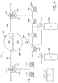
- FIG. 1 an example of an HD flow schematic for a medical fluid delivery system 10 employing a pneumatic pump box of the present disclosure is illustrated. Because the HD system of Fig. 1 is relatively complicated, Fig. 1 and its discussion also provide support for any of the renal failure therapy modalities discussed above and for an IV machine. Generally, system 10 is shown having a very simplified version of a dialysis fluid or process fluid delivery circuit. The blood circuit is also simplified but not to the degree that the dialysis fluid circuit is simplified. It should be appreciated that the circuits have been simplified to make the description of the present disclosure easier, and that the systems if implemented would have additional structure and functionality, such as is found in the publications incorporated by reference above.
- System 10 of Fig 1 includes a blood circuit 20.
- Blood circuit 20 pulls blood from and returns blood to a patient 12. Blood is pulled from patient 12 via an arterial line 14, and is returned to the patient via a venous line 16.
- Arterial line 14 includes an arterial line connector 14a that connects to an arterial needle 14b, which is in blood draw communication with patient 12.
- Venous line 16 includes a venous line connector 16a that connects to a venous needle 16b, which is in blood return flow communication with the patient.
- Arterial and venous lines 14 and 16 also include line clamps 18a and 18v, which can be spring-loaded, fail-safe mechanical pinch clamps. Line clamps 18a and 18v are closed automatically in an emergency situation in one embodiment.
- Arterial and venous lines 14 and 16 also include air or bubble detectors 22a and 22v, respectively, which can be ultrasonic air detectors. Air or bubble detectors 22a and 22v look for air in the arterial and venous lines 14 and 16, respectively. If air is detected by one of air detectors 22a and 22v, system 10 closes line clamps 18a and 18v, pauses the blood and dialysis fluid pumps, and provides instructions to the patient to clear the air so that treatment can resume.
- air or bubble detectors 22a and 22v look for air in the arterial and venous lines 14 and 16, respectively. If air is detected by one of air detectors 22a and 22v, system 10 closes line clamps 18a and 18v, pauses the blood and dialysis fluid pumps, and provides instructions to the patient to clear the air so that treatment can resume.
- a blood pump 30 is located in arterial line 14 in the illustrated embodiment.
- blood pump 30 includes a first blood pump pod 30a and a second blood pump pod 30b.
- Blood pump pod 30a operates with an inlet valve 32i and an outlet valve 32o.
- Blood pump pod 30b operates with an inlet valve 34i and an outlet valve 34o.
- blood pump pods 30a and 30b are each blood receptacles that include a hard outer shell, e.g., spherical, with a flexible diaphragm located within the shell, forming a diaphragm pump.
- One side of each diaphragm receives blood, while the other side of each diaphragm is operated by negative and positive air pressure.
- Blood pump 30 is alternatively a peristaltic pump operating with the arterial line 14 tube.
- a heparin vial 24 and heparin pump 26 are located between blood pump 30 and blood filter 40 (e.g., dialyzer) in the illustrated embodiment.
- Heparin pump 26 may be a pneumatic pump or a syringe pump (e.g., stepper motor driven syringe pump). Supplying heparin upstream of blood filter 40 helps to prevent clotting of the filter's membranes.
- a control unit 50 includes one or more processor and memory. Control unit 50 receives air detection signals from air detectors 22a and 22v (and other sensors of system 10, such as temperature sensors, blood leak detectors, conductivity sensors, pressure sensors, and access disconnection transducers 102, 104), and controls components such as line clamps 18a and 18v, blood pump 30, heparin pump 26, and the dialysis fluid pumps. Blood exiting blood filter 40 via venous line 16 flows through an airtrap 110. Airtrap 110 removes air from the blood before the dialyzed blood is returned to patient 12 via venous line 16.
- dialysis fluid or dialysate is pumped along the outside of the membranes of blood filter 40, while blood is pumped through the insides of the blood filter membranes.
- Dialysis fluid or dialysate is prepared beginning with the purification of water via a water purification unit 60.
- One suitable water purification unit is set forth in U.S. Patent Publication No. 2011/0197971 , entitled, “Water Purification System and Method", filed Apr. 25, 2011, the entire contents of which are incorporated herein by reference and relied upon.
- water purification unit includes filters and other structures to purify tap water (e.g., remove pathogens and ions such as chlorine), so that the water is in one implementation below 0.03 endotoxin units/ml ("EU/ml”) and below 0.1 colony forming units/ml (“CFU/ml”).
- Water purification unit 60 may be provided in a housing separate from the housing of the hemodialysis machine, which includes blood circuit 20 and a dialysis fluid circuit 70.
- Dialysis fluid circuit 70 is again highly simplified in Fig. 1 to ease illustration. Dialysis fluid circuit 70 in actuality may include all of the relevant structure and functionality set forth in the publications incorporated by reference above. Certain features of dialysis fluid circuit 70 are illustrated in Fig. 1 .
- dialysis fluid circuit 70 includes a to-blood filter dialysis fluid pump 64.
- Pump 64 is in one embodiment configured the same as blood pump 30.
- Pump 64 like pump 30, includes a pair of pump pods, which again may be spherically configured. The two pump pods, like with blood pump 30, are operated alternatingly so that one pump pod is filling with HD dialysis fluid, while the other pump pod is expelling HD dialysis fluid.
- Pump 64 is a to-blood filter dialysis fluid pump.
- the third and fourth pumps, the concentrate pumps may be single pod pumps because continuous pumping is not as important in mixing line 62 because there is a buffering dialysis fluid tank (not illustrated) between mixing line 62 and to-blood filter dialysis fluid pump 64 in one embodiment.
- a fifth pod pump (not illustrated) provided in drain line 82 is used to remove a known amount of ultrafiltration ("UF") when an HD therapy is provided.
- System 10 keeps track of the UF pump to control and know how much ultrafiltrate has been removed from the patient. System 10 ensures that the necessary amount of ultrafiltrate is removed from the patient by the end of treatment.
- Each of the above-described pumps may alternatively be a peristaltic pump operating with a tube. If so, the system valves may still be actuated pneumatically according to the features of the present disclosure.
- purified water from water purification unit 60 is pumped along mixing line 62 though bicarbonate cartridge 72.
- Acid from container 74 is pumped along mixing line 62 into the bicarbonated water flowing from bicarbonate cartridge 72 to form an electrolytically and physiologically compatible dialysis fluid solution.
- the pumps and temperature-compensated conductivity sensors used to mix the purified water properly with the bicarbonate and acid are not illustrated but are disclosed in detail in the publications incorporated by reference above.
- Fig. 1 also illustrates that dialysis fluid is pumped along a fresh dialysis fluid line 76, through a heater 78 and an ultrafilter 80, before reaching blood filter 40, after which used dialysis fluid is pumped to drain via drain line 82.
- Heater 78 heats the dialysis fluid to body temperature or about 37° C.
- Ultrafilter 80 further cleans and purifies the dialysis fluid before reaching blood filter 40, filtering bugs or contaminants introduced for example via bicarbonate cartridge 72 or acid container 74 from the dialysis fluid.
- Dialysis fluid circuit 70 also includes a sample port 84 in the illustrated embodiment. Dialysis fluid circuit 70 will further include a blood leak detector (not illustrated but used to detect if a blood filter 40 fiber is torn) and other components that are not illustrated, such as balance chambers, plural dialysis fluid valves, and a dialysis fluid holding tank, all illustrated and described in detail in the publications incorporated by reference above.
- a blood leak detector not illustrated but used to detect if a blood filter 40 fiber is torn
- other components that are not illustrated, such as balance chambers, plural dialysis fluid valves, and a dialysis fluid holding tank, all illustrated and described in detail in the publications incorporated by reference above.
- hemodialysis system 10 is an online, pass-through system that pumps dialysis fluid through blood filter one time and then pumps the used dialysis fluid to drain.
- Both blood circuit 20 and dialysis fluid circuit 70 may be hot water disinfected after each treatment, such that blood circuit 20 and dialysis fluid circuit 70 may be reused.
- blood circuit 20 including blood filter 40 is hot water disinfected and reused daily for about one month, while dialysis fluid circuit 70 is hot water disinfected and reused for about six months.
- CRRT for example, multiple bags of sterilized dialysis fluid or infusate are ganged together and used one after another.
- the emptied supply bags can serve as drain or spent fluid bags.
- the machine 90 of system 10 includes an enclosure as indicated by the dotted line of Fig. 1 .
- the enclosure of machine 90 varies depending upon the type of treatment, whether the treatment is in-center or a home treatment, and whether the dialysis fluid/infusate supply is a batch-type (e.g., bagged) or on-line.
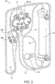
- Fig. 2 illustrates that machine 90 of system 10 of Fig. 1 may operate with a blood set 100.
- Blood set 100 includes arterial line 14, venous line 16, heparin vial 24, heparin pump 26/blood pump 30 and blood filter 40 (e.g., dialyzer).
- An airtrap 110 may be located in venous line 16 to remove air from the blood before being returned to patient 12.
- any of pumps 26, 30 (30a and 30b), 64, 96 (and other pumps not illustrated) and any of the valves, such as valves 32i, 32o, 34i, 34o, 68i, 68o, 98i and 98o may be pneumatically actuated.
- each of the pumps and valves has a fluid side and an air side, separated by a flexible membrane. Negative pneumatic pressure may be applied to the air side of the membrane to draw fluid into a pump chamber or to open a valve (or pump or valve could be opened by venting positive closing pressure to atmosphere and allowing fluid pressure to open). Positive pneumatic pressure is applied to the air side of the membrane to expel fluid from a pump chamber or to close a valve.
- Medical fluid delivery machine 90 in the illustrated embodiment includes a medical fluid delivery chassis 120 connected to a pneumatic pump box 150.
- pneumatic pump box 150 is connected removeably to medical fluid delivery chassis 120, so that the pump box can be moved away from the patient (e.g., placed in a closet) to reduce noise in the treatment area near the vicinity of the patient.
- At least one positive pneumatic line and at least one negative pneumatic line run from pneumatic pump box 150 to medical fluid delivery chassis 120 to drive pumps 26, 30 (30a and 30b), 64, 96 (and other pumps not illustrated) and any of the valves, such as valves 32i, 32o, 34i, 34o, 68i, 680, 98i and 98o, which are located within or are mounted onto medical fluid delivery chassis 120.
- pneumatic components such as, pneumatic regulators, electrically actuated binary solenoid valves, and electrically actuated variable pneumatic (vari-valves) are located within medical fluid delivery chassis 120.
- the number of pneumatic lines running from pneumatic pump box 150 to medical fluid delivery chassis 120 can therefore be minimized, perhaps to a single positive pressure pneumatic line and a single negative pressure pneumatic line.
- Figs. 4A and 4B illustrate alternative pneumatic pump boxes 150a and 150b (collectively pump box 150) in more detail.
- Pump boxes 150a and 150b have been simplified to highlight their primary components and may contain other structure, not illustrated, such as electrical wiring and circuitry, tubing, connectors, etc.
- Pneumatic pump boxes 150a and 150b of Figs. 4A and 4B respectively, recognize that the vacuum pump 152 produces heat and accordingly forms the hottest point in the pump box during operation. Vacuum pump 152 is accordingly mounted at the top within both pneumatic pump boxes 150a and 150b, so that heat may rise up and away from the other pump box components.
- Pneumatic pump box 150a also reduces and simplifies the routing of tubing within the pneumatic pump box as much as possible. To do so, pneumatic pump box 150a locates a compressor 154 at the bottom of pneumatic pump box 150a. Compressor 154 feeds compressed air into a dryer 156 via a short pneumatic line 162. Dryer 156 in an embodiment cools the compressed air from compressor 154, condensing water out of compressed air. Removing water from the air prior to use is important because water in the compressed air volume can cause system failure due to corrosion. Because dryer 156 operates in an embodiment via cooling, it is prudent to locate dryer 156 away from the heat-producing vacuum pump 152.
- dryer 156 is located beneath vacuum pump 152, avoiding its rising heat, and is separated from vacuum pump 152 via accumulators 158 and 160.
- Tubing routing is likewise simplified and reduced via short pneumatic line 164 between dryer 156 and positive pressure accumulator 158 and short tubing line 166 between vacuum pump 152 and negative pressure accumulator 160.
- Positive pressure accumulator 158 includes an output port 159 for connecting to a positive pressure pneumatic line (not illustrated), supplying positive pressure to medical fluid delivery chassis 120.
- Negative pressure accumulator 160 includes an output port 161 for connecting to a negative pressure pneumatic line (not illustrated), supplying negative pressure to medical fluid delivery chassis 120.
- Alternative pneumatic pump box 150b flips the placement of compressor 154 and dryer 156 relative to pneumatic pump box 150a, so that compressor 154 instead lies above dryer 156.
- This configuration moves cooling dryer 156 further away from heat-producing vacuum pump 152 and also below heat rising from the compressor, which is advantageous, but requires a longer pneumatic line 164 between dryer 156 and positive pressure accumulator 158.
- component layouts of both pneumatic pump box 150a and 150b are made with efficiency and simplicity in mind.
- Either one or both of pneumatic pump boxes 150a and 150b may provide an electrically operated fan 170 at the top of the box, which is oriented to pull heated air from vacuum pump 152 out of the box.
- inlet vents 172 may be provided and located as illustrated just beneath the location of vacuum pump 152.
- relatively cool air is pulled in through vents 172 and about vacuum pump 152 via fan 172, which also exhausts the heated out of pneumatic pump box 150a or 150b.
- Either one or both of pneumatic pump boxes 150a and 150b may also provide sound insulation 174 on one or more or all of the inner walls of the pump boxes.
- Sound insulation 174 such as foam or rockwool, lining the inner walls of pump boxes 150a and 150b, helps to muffle noise produced via pneumatic components 152, 154 and 156.
- the insulation may eliminate the need to remove pump box 150 from medical fluid delivery chassis 120. Indeed, it is contemplated to integrate pump box 150, including any of the disclosure and alternatives described herein, into medical fluid delivery chassis 120 of machine 90.
- positive pressure accumulator 158 includes a rigid outer housing 176, which can be made of a plastic material, such as polyvinylchloride (“PVC"), polycarbonate (“PC”), polypropylene (“PP”), polyethylene (“PE”), for example.
- Rigid outer housing 176 in the illustrated embodiment has an inner surface that attempts two eliminate sharp corners and instead includes relatively large radius bends 178 that enable a bladder to conform readily to a shape of the inner surface, to use all or substantially all of the inner volume defined by the inner surface.
- the inner volume defined by rigid housing may be from about 250 milliliters to a liter or more, e.g., 500 milliliters.
- Rigid outer housing 176 in the illustrated embodiment includes or provides a vent port 186.
- Vent port 186 is in one embodiment molded with the rest of rigid housing 176. Vent port 186 allows a bladder 182 described below to push air out of housing 176 when bladder 182 expands and for air to enter housing 176 when bladder 182 contracts. Housing 176 nevertheless provides the ridged enclosure needed to contain the bladder 182. Port 186 helps the bladder to expand fully and contract readily.
- An open end of rigid outer housing 176 in the illustrated embodiment accepts a bladder assembly 180 illustrated in Fig. 6 .
- Bladder assembly 180 includes an expandable bladder 182.
- Expandable bladder 182 is made of a highly elastic material, such as latex.
- Fig. 6 illustrates that the open end 184 of bladder 182 is stretched and sealed over a bladder connection end 192 of a connector 190.
- Connector 190 also provides output ports 159, 161 described above in connection with Figs. 4A and 4B , respectively, for connecting to positive or negative pressure lines (not illustrated), supplying positive or negative pressure to medical fluid delivery chassis 120.
- Output ports 159, 161 may be barbed as illustrated for sealed connection with the pneumatic lines, or have other suitable airtight sealing connections.
- Connector 190 may be made from any of the rigid plastics described above for rigid outer housing 176, including nylon additionally.
- Connector 190 may also be injection molded to provide closer tolerances than can be achieved via blow molding, which may be used to form rigid
- a gasket 188 such as an o-ring gasket further compresses expandable bladder 182 onto bladder connection end 192 of a connector 190.
- Bladder connection end 192 in an embodiment provides an annular indent to seat gasket 188 onto bladder 182 and bladder connection end.
- Gasket 188 is also sized to compresses within a neck 179 of rigid outer housing 176 when bladder assembly 180 is inserted into outer housing 176.
- a flange 194 of connector 190 seats against the front of neck 179 when bladder assembly 180 is fully inserted into outer housing 176.
- Gasket 188 may be made of silicon or other compressible rubber or plastic.
- both output ports 159, 161 and bladder connection end 192 of connector 190 are barbed.
- Housing 176 and its neck 179 may be made of a softer material than barbed connection end 192 of connector 190, such that the barbs can dig into and seal to neck 179 of housing 176.
- output ports 159, 161 of connector 190 may be smooth and seal to a pneumatic tube via one or more o-ring gasket, e.g., fitted into groove formed in output ports 159, 161.
- bladder connection end 192 can be smooth as illustrated or barbed as described alternatively above.
- a positive pressure regulator such as a static regulator or a vari-valve, sets the operating pressure at the fluid pump chamber or fluid valve chamber to 5 psig. It is contemplated then to construct bladder 182 (e.g., via setting its wall thickness), so that it requires at least slightly above 5 psig, such as 5.5psig, to inflate the bladder. The pressure needed to inflate the bladder also needs to be below the output pressure of compressor 154 and dryer 156. By doing so, bladder 182 provides sufficient operating pressure to the regulator when the bladder contracts from its expanded shape illustrated in Fig. 7 to its resting shape illustrated in Figs. 5 and 6 .
- bladder 182 Without bladder 182, once the pressure in rigid outer housing 176 falls to 5 psig in the example, accumulator 158 can no longer power a fluid valve or pump. But with bladder 182, once the pressure in rigid outer housing 176 falls to the bladder inflation pressure (e.g., slightly above 5 psig or 5.5 psig in the example), bladder 182 supplies the bladder inflation pressure to the regulator, e.g., 5.5 psig, until bladder 182 reaches its resting shape.
- the bladder inflation pressure e.g., slightly above 5 psig or 5.5 psig in the example
- Fig. 8A illustrates a graph of the pressure provided by accumulator 158 over time, showing the pressure (i) start at the initial positive pressure provided by compressor 154 to accumulator 158, (ii) fall either linearly or according to a curve to the bladder inflation pressure, (iii) remain at the inflation pressure until bladder 182 reaches its non-expanded resting shape, and (iv) fall to the regulated output pressure.
- the additional amount or volume may be used, for example, to drive a pump or valve chamber when power to compressor 154 is no longer available.
- the additional amount or volume may also be used to lessen the leak-tightness requirements for the pneumatic components, such as the regulators, binary solenoid valves and vari-valves. Lessening such requirements may allow of a cheaper valve to be used and/or lessen the number of fault situations when such pneumatic components are tested before treatment.
- Figs. 5 to 7 also illustrate an embodiment of negative pressure accumulator 160.
- All of the above structure and alternatives described above for positive pressure accumulator 158 are the same for negative pressure accumulator 160, except that (i) bladder 182, e.g., made of latex, silicone or other flexible material, is thickened to have a higher inflation pressure and (ii) the roles of vent port 186 and connector 190 are reversed, so that vent port becomes the vacuum source port and connector 190 becomes the air vent.
- vacuum pump 152 draws a vacuum on port 186, which evacuates the air between bladder 182 and rigid outer housing 176, while air is able to enter the inside of bladder 182 via connector 190 to backfill the bladder.
- Negative pressure bladder 182 is structured (e.g., via setting its wall thickness), such that it takes a full vacuum amount of negative pressure to inflate the bladder in one embodiment. For example, if it is desired to charge negative pressure accumulator 160 to - 15psig, negative pressure bladder 182 may be structured such that it takes -15psig to inflate the bladder, assuming vacuum pump 152 can provide at least -15psig. In this manner, the space between fully contracted bladder 182 and rigid outer housing 176 is fully evacuated to a full, desired amount prior to bladder inflating to cover vacuum inlet port 186.
- the bladder and the ridged outer housing accumulator are configured so that a full vacuum can be drawn before the negative pressure bladder expands to block or fully block the vacuum port provided by the housing, and/or (ii) the vacuum port can be angled on the inside of the rigid housing so that it is difficult for the bladder to block.
- bladder 182 begins to contract, supplying the negative inflation pressure until the bladder is contracted fully.
- rigid outer housing 176 is left with a fully charged vacuum.
- Fig. 8B illustrates a graph of the negative pressure provided by accumulator 160 over time, showing the pressure (i) start at the initial negative pressure setpoint provided by vacuum pump 152 to accumulator 160, (ii) fall slightly to or just below the negative inflation pressure of bladder 182, (iii) remain at the negative inflation pressure until bladder 182 is fully contracted, and (iv) fall either linearly or according to a curve to a negative regulated output pressure.
- Vent 190 allows air to escape the inside of bladder 182 so that the bladder may contract fully.
- positive pressure accumulator 158 versus negative pressure accumulator 160 is as follows: (pos) positive pressure chamber pressure +15psig, positive pressure bladder inflation pressure +5.5psig, positive pressure regulated output pressure +5.0psig, versus (neg) negative pressure chamber pressure -15psig, negative pressure bladder inflation pressure -14.5 psig, negative pressure regulated output pressure -5.0psig.
- battery power may be provided with accumulators 158 and 160 and associated bladders 182 to power the electrically operated solenoid and vari-valves, so that negative and positive pressure may be applied to a medical fluid pump 200 including a pneumatically actuated pump chamber 202 and first and second pneumatically actuated medical fluid valve chambers 212 and 222 located respectively upstream and downstream of the pneumatically actuated pump chamber 202.
- Binary solenoid valves 240a to 240f are in one embodiment spring closed and powered open, so that batter power is only needed to open the valves.
- Vari-valve 244 needs power throughout its operation.
- Static pneumatic regulators 246 and 248 in one embodiment do not need power.
- Static pneumatic regulators 246 and 248 set constant positive and negative pneumatic operating pressures as discussed above.
- the blood set 100 of Fig. 2 to rinse blood back to the patient towards connectors 14a and 16a through the blood set using dialysis fluid across dialyzer 40 to push the blood, battery power is needed to open the solenoids and operate the vari-valves associated with the blood pump (which may be configured like pump 200) and/or a fresh dialysis fluid pump (which may be configured like pump 200).
- Balance chambers may also be employed, which are bypassed for rinseback in one embodiment.
- the used dialysis fluid pump may be shut down (inlet and outlet valves closed), so that positive dialysis fluid pressure may be built in the dialyzer for the dialysis fluid flow into the blood set to push blood back towards the patient.
- pneumatically actuated pump chamber 202 includes a housing 204, e.g., a rigid plastic housing, defining a medical fluid side 206 (e.g., blood, dialysis fluid, substiution fluid, intravenous drug) and a pneumatic side 208, separated by a flexible membrane or diaphragm 210.
- Pneumatically actuated first or inlet valve 212 includes a housing 214, e.g., a rigid plastic housing, defining a medical fluid side 216 and a pneumatic side 218, separated by a flexible membrane or diaphragm 220.
- Pneumatically actuated second or outlet valve 222 includes a housing 224, e.g., a rigid plastic housing, defining a medical fluid side 226 and a pneumatic side 228, separated by a flexible membrane or diaphragm 230.
- Inlet valve 212 selectivelty allows medical fluid to flow to pump chamber 202 via medical fluid inlet line 232
- outlet valve 222 selectivelty allows medical fluid to flow from pump chamber 202 via medical fluid outlet line 234.
- inlet valve 212 To draw medical fluid into pump chamber 202, inlet valve 212 is opened, outlet valve 222 is closed and negative pneumatic pressure is applied to pumping membrane 210 to pull the membrane towards vari-valve 244, sucking fluid into pump chamber 202 via inlet line 232.
- inlet valve 212 To push medical fluid from pump chamber 202, inlet valve 212 is closed, outlet valve 222 is opened and positive pneumatic pressure is applied to pumping membrane 210 to push the membrane away from vari-valve 244, pushing fluid from pump chamber 202 via outlet line 234.
- Vari-valve 244 includes a varaible orifice that allows a desired variation of positive and/or negative pneumatic pressure, within ranges set by pneumatic regulators 246 and 248, over the course of a stroke of pump chamber 202.
- Binary valve 240c (e.g., spring closed, energized open) selectivly allows regulated negative pressure to reach vari-valve 244, while binary valve 240d (e.g., spring closed, energized open) selectivly allows regulated positive pressure to reach vari-valve 244.
- first or inlet valve 212 and second or outlet valve 222 are closed under positive pressure and opened to atmosphere.
- binary valve 240b is opened, while binary valve 240a is closed, allowing regulated positive pressure to close inlet valve 212 and to prevent the positive pressure from venting to atmosphere.
- binary valve 240b is closed, while binary valve 240a is opened, preventing regulated positive pressure from reaching inlet valve 212 and enabling the existing positive pressure at inlet valve 212 to vent to atmosphere.
- binary valve 240e is opened, while binary valve 240f is closed, allowing regulated positive pressure to close outlet valve 222 and to prevent the positive pressure from venting to atmosphere.
- binary valve 240e is closed, while binary valve 240f is opened, preventing regulated positive pressure from reaching outlet valve 222 and enabling the existing positive pressure at outlet valve 222 to vent to atmosphere.
- Binary valves 240a to 240f and vari-valve 244 are operated under the control of control unit 50 (also showing dashed electrical lines).
- Control unit 50 runs a computer program that sequences binary valves 240a to 240f as discussed above and controls the orifice size of vari-valve 244 to create a desired pumping pressure profile.
- Inlet and outlet valves 212 and 222 may open when vented to atmosphere via medical fluid pressure, forcing valve membranes 220 and 230 open, and/or by forming valve membranes 220 and 230 to be preformed or predomed into a sphere or dome and orienting the dome towards the pneumatic inlet, such that the natrual bias of the membrane itself causes or tends to cause the inlet and outlet valves 212 and 222 to open when not subjected to positive pneumatic pressure.
- inlet and outlet valves 212 and 222 do not require negative pressure, and more positive pressure is therefore needed to operate medical fluid pump 200 than negative pressure.
- negative pressure is used to open inlet and outlet valves 212 and 222, and thus a roughly equal amount positive and negative pressure is needed to operate medical fluid pump 200.
- bladder 182 may be provided with both positive and negative pressure accumulators 158 and 160 to extend the life of medical fluid pump 200 upon power loss.
Landscapes
- Health & Medical Sciences (AREA)
- Engineering & Computer Science (AREA)
- Heart & Thoracic Surgery (AREA)
- Mechanical Engineering (AREA)
- General Engineering & Computer Science (AREA)
- Anesthesiology (AREA)
- Veterinary Medicine (AREA)
- Biomedical Technology (AREA)
- Hematology (AREA)
- Life Sciences & Earth Sciences (AREA)
- Animal Behavior & Ethology (AREA)
- General Health & Medical Sciences (AREA)
- Public Health (AREA)
- Urology & Nephrology (AREA)
- Vascular Medicine (AREA)
- Emergency Medicine (AREA)
- Pulmonology (AREA)
- Physics & Mathematics (AREA)
- Fluid Mechanics (AREA)
- External Artificial Organs (AREA)
- Infusion, Injection, And Reservoir Apparatuses (AREA)
- Reciprocating Pumps (AREA)
Abstract
Description
- This application claims priority to
U.S. Patent Application No. 15/336,266, filed October 27, 2016 - The present disclosure relates generally to devices, systems and methods for medical fluid delivery machines. More specifically, the present disclosure relates to medical fluid delivery machines, such as renal failure therapy machines, that employ pneumatic pumping.
- Regarding renal failure therapy machines, due to various causes, a person's renal system can fail. Renal failure produces several physiological derangements. It is no longer possible to balance water and minerals or to excrete daily metabolic load. Toxic end products of nitrogen metabolism (urea, creatinine, uric acid, and others) can accumulate in blood and tissue.
- Kidney failure and reduced kidney function have been treated with dialysis. Dialysis removes waste, toxins and excess water from the body that normal functioning kidneys would otherwise remove. Dialysis treatment for replacement of kidney functions is critical to many people because the treatment is life saving.
- One type of kidney failure therapy is Hemodialysis ("HD"), which in general uses diffusion to remove waste products from a patient's blood. A diffusive gradient occurs across the semi-permeable dialyzer between the blood and an electrolyte solution called dialysate or dialysis fluid to cause diffusion.
- Hemofiltration ("HF") is an alternative renal replacement therapy that relies on a convective transport of toxins from the patient's blood. HF is accomplished by adding substitution or replacement fluid to the extracorporeal circuit during treatment (typically ten to ninety liters of such fluid). The substitution fluid and the fluid accumulated by the patient in between treatments is ultrafiltered over the course of the HF treatment, providing a convective transport mechanism that is particularly beneficial in removing middle and large molecules (in hemodialysis there is a small amount of waste removed along with the fluid gained between dialysis sessions, however, the solute drag from the removal of that ultrafiltrate is not enough to provide convective clearance).
- Hemodiafiltration ("HDF") is a treatment modality that combines convective and diffusive clearances. HDF uses dialysis fluid flowing through a dialyzer, similar to standard hemodialysis, to provide diffusive clearance. In addition, substitution solution is provided directly to the extracorporeal circuit, providing convective clearance.
- Most HD (HF, HDF) treatments occur in centers. A trend towards home hemodialysis ("HHD") exists today in part because HHD can be performed daily, offering therapeutic benefits over in-center hemodialysis treatments, which occur typically bi- or triweekly. Studies have shown that frequent treatments remove more toxins and waste products than a patient receiving less frequent, but perhaps longer treatments. A patient receiving more frequent treatments does not experience as much of a down cycle as does an in-center patient, who has built-up two or three days' worth of toxins prior to a treatment. In certain areas, the closest dialysis center can be many miles from the patients' home causing door-to-door treatment time to consume a large portion of the day. HHD may take place overnight or during the day while the patient relaxes, works or is otherwise productive.
- Another type of kidney failure therapy is peritoneal dialysis, which infuses a dialysis solution, also called dialysis fluid, into a patient's peritoneal cavity via a catheter. The dialysis fluid contacts the peritoneal membrane of the peritoneal cavity. Waste, toxins and excess water pass from the patient's bloodstream, through the peritoneal membrane and into the dialysis fluid due to diffusion and osmosis, i.e., an osmotic gradient occurs across the membrane. An osmotic agent in dialysis provides the osmotic gradient. The used or spent dialysis fluid is drained from the patient, removing waste, toxins and excess water from the patient. This cycle is repeated, e.g., multiple times.
- There are various types of peritoneal dialysis therapies, including continuous ambulatory peritoneal dialysis ("CAPD"), automated peritoneal dialysis ("APD"), and tidal flow dialysis and continuous flow peritoneal dialysis ("CFPD"). CAPD is a manual dialysis treatment. Here, the patient manually connects an implanted catheter to a drain to allow used or spent dialysate fluid to drain from the peritoneal cavity. The patient then connects the catheter to a bag of fresh dialysis fluid to infuse fresh dialysis fluid through the catheter and into the patient. The patient disconnects the catheter from the fresh dialysis fluid bag and allows the dialysis fluid to dwell within the peritoneal cavity, wherein the transfer of waste, toxins and excess water takes place. After a dwell period, the patient repeats the manual dialysis procedure, for example, four times per day, each treatment lasting about an hour. Manual peritoneal dialysis requires a significant amount of time and effort from the patient, leaving ample room for improvement.
- Automated peritoneal dialysis ("APD") is similar to CAPD in that the dialysis treatment includes drain, fill and dwell cycles. APD machines, however, perform the cycles automatically, typically while the patient sleeps. APD machines free patients from having to perform the treatment cycles manually and from having to transport supplies during the day. APD machines connect fluidly to an implanted catheter, to a source or bag of fresh dialysis fluid and to a fluid drain. APD machines pump fresh dialysis fluid from a dialysis fluid source, through the catheter and into the patient's peritoneal cavity. APD machines also allow for the dialysis fluid to dwell within the cavity and for the transfer of waste, toxins and excess water to take place. The source may include multiple sterile dialysis fluid solution bags.
- APD machines pump used or spent dialysate from the peritoneal cavity, though the catheter, and to the drain. As with the manual process, several drain, fill and dwell cycles occur during dialysis. A "last fill" occurs at the end of APD and remains in the peritoneal cavity of the patient until the next treatment.
- Any of the above modalities performed by a machine may employ pneumatic pumping. Pneumatic pumping typically involves the application of positive and/or negative air pressure to a pumping membrane or diaphragm. Positive pressure may be provided via a compressor feeding a positive pressure tank or accumulator. Negative pressure may be provided via a vacuum pump feeding a negative pressure tank or accumulator. Attempts may be made to remove water from the positive pressure prior to the air being fed to the positive pressure tank accumulator. Water present in positive pressure air can lead to corrosion within the solenoid valves and elsewhere.
- The components described above may generate heat or may operate more effectively in a non-heated environment. An improved coordination of such components is needed accordingly.
- Additionally, the positive pressure accumulator is effective only until its pressure reaches that needed to drive a certain application. For example, a pressure regulator may be present between the positive pressure accumulator and the application, e.g., a fluid valve. If the regulator is set to deliver 5 psig to close the valve, for example, then the accumulator cannot deliver the pressure necessary to close the valve once its pressure falls below 5 psig. There may be situations in which it is desirable to have the positive and negative accumulators deliver positive and negative pressure, respectively, for as long as possible. An additional need exists accordingly to extend the useful life of the pneumatic pressure accumulators.
- The examples described herein disclose pump box devices, systems and methods therefore applicable, for example, to fluid delivery for: plasmapherisis, hemodialysis ("HD"), hemofiltration ("HF") hemodiafiltration ("HDF"), and continuous renal replacement therapy ("CRRT") treatments. The pump box devices, and systems and methods therefore described herein are also applicable to peritoneal dialysis ("PD") and to intravenous drug delivery. These modalities may be referred to collectively or generally individually as medical fluid delivery.
- Moreover, each of the devices, systems and methods described herein may be used with clinical or home-based machines. For example, the systems may be employed in in-center HD, HF or HDF machines, which run throughout the day. Alternatively, the systems may be used with home HD, HF or HDF machines, which are operated at the patient's convenience. One such home system is described in
U.S. Patent No. 8,029,454 ("the '454 Patent"), issued October 4, 2011, entitled "High Convection Home Hemodialysis/Hemofiltration And Sorbent System", filed November 4, 2004, assigned to the assignee of the present application. Another such home system is described inU.S. Patent No. 8,393,690 ("the '690 Patent"), issued March 12, 2013, entitled "Enclosure for a Portable Hemodialysis System", filed August 27, 2008. The entire contents of each of the above references are incorporated herein by reference and relied upon. - In an embodiment, a medical fluid delivery machine is provided that includes a medical fluid delivery chassis. The medical fluid delivery chassis houses components needed to deliver medical fluid, such as one or more pump, plural valves, a heater if needed, online medical fluid generation equipment if needed and desired, plural sensors, such as any one, or more, or all of pressure sensors, conductivity sensors, temperature sensors, air detectors, blood leak detectors, and the like, a user interface, and a control unit, which may employ one or more processor and memory to control the above-described equipment.
- Various components, such as the fluid pumps and valves, may be actuated pneumatically. In such a case, it is contemplated to provide a pneumatic pump box, which houses equipment needed to generate and store positive and/or negative pressure air. "Air" as used herein means air as it exists naturally, which is made up of individual gases such as nitrogen, oxygen, argon, and carbon dioxide. "Air" may also include a desired modified atmosphere, such as a larger percentage of, or a pure gas, such nitrogen or carbon dioxide. The term "pneumatic" also refers to naturally occurring air and/or any type of modified atmosphere.
- The pneumatic pump box may house components, such as a vacuum pump for supplying negative air pressure, a compressor for supplying positive air pressure, a dryer for removing water from the positive pressure air outputted from the compressor prior to storage in the accumulator, and positive and negative accumulators for storing positive and negative air pressure, respectvely. The pneumatic pump box may be attached removeably to the medical fluid delivery chassis. If the medical fluid delivery machine is to be operated while the patient is sleeping, for example, or if the patient desires a quiet environment for whatever reason, it may be desirable for the patient to remove the pneumatic pump box and store it in a closet or other remote location to dampen its noise. The removable pneumatic pump box is connected pneumatically to the medical fluid delivery chassis via one or more positive and negative pressure lines and may receive electrical power via its own electrical cord or via an electrical power feed from the chassis.
- The pneumatic pump box's vacuum pump is typically the hottest point in the box during operation. The dryer in an embodiment cools air from the compressor to condense water from the compressed air, so that the water may be removed before being delivered into the positive pressure accumulator. Removing water from the compressed air is important because water in the compressed air volume may cause system failure due to corrosion. The pneumatic box of the present disclosure accordingly places the vacuum pump at the top of the pneumatic pump box. Here, heat rises from the vacuum pump to the top of the box, such that its impact on the other components in the box is minimized. It is further contemplated to place a small, inexpensive fan directly in the top of the box directly above the dryer, which is oriented to pull the heated air out of the box. Intake vents for the fan may be provided in the pump box, e.g., just below the vacuum pump.
- With the vacuum pump placed at the top of the pump box, the goals for locating the remainder of the equipment are two-fold, namely, (i) to locate the dryer as far away from the vacuum pump as possible to prevent heat generated from the vacuum pump from heating the dryer, and (ii) to reduce and simplify the routing of tubing between the pneumatic pump box as much as possible. To this end, either the compressor or the dryer may be located at the bottom of the box. Locating the compressor at the bottom of the box, the dryer above the compressor and the accumulators above the dryer optimizes the routing of tubing and other air connections, which run from the compressor to the dryer, and from the dryer to the positive pressure accumulator. On the other hand, locating the dryer at the bottom of the box, the compressor above the dryer, and the accumulators above the compressor, spaces the dryer (e.g., chilling device) as far away as possible from the heat-producing vacuum pump.
- In an embodiment, the pneumatic pump box includes two accumulators, namely, a positive pressure accumulator and a negative pressure accumulator. It is possible that the pneumatic pump and valve control may use different pressure levels at different locations within the medical fluid delivery machine. For example, a pneumatic pump may include a pump chamber associated with its own inlet and outlet valve chambers, wherein the pressure applied to the valve chambers is greater than the pressure applied to the pump chamber, so that operation of the pump chamber does not affect a desired valve state. In another example, it may be desirable to apply less pressure to a blood pump operation than to a dialysis fluid operation, to better avoid damaging blood cells or other blood components. In any case, multiple accumulators may be provided to store multiple positive and/or negative pressures. In one preferred embodiment, however, a single positive pressure accumulator and a single negative pressure accumulator are provided to feed multiple pneumatic regulators that set the different desired positive and/or negative pneumatic operating pressures.
- The pneumatic regulators may include static regulators that set a desired positive or negative pneumatic pressure, for example, to feed multiple on/off or binary applications. The pneumatic regulators may alternatively or additionally include a variable diameter orifice, e.g., as a variable valve or vari-valve. Components, such as the pneumatic regulators, binary pneumatic valves and the vari-valves are placed in an embodiment on a manifold that is located inside the medical fluid delivery chassis, so that single positive and negative pressure lines from the pneumatic pump box to the chassis can feed each of the components of the manifold.
- To improve the efficiency of the accumulators, it is contemplated to sealingly secure an elastic accumulator bladder inside of an outer, rigid positive pressure accumulator housing, which limits the size to which the bladder can expand, and also defines the shape of the bladder when expanded to fill the volume of the accumulator housing fully. The bladder is formed to require a certain positive pressure for inflation, namely, the bladder inflation pressure. The rigid outer chamber is vented in an embodiment, so that air between the bladder and rigid outer chamber can be displaced to atmosphere when the bladder is inflated. When positive pressure air is withdrawn initially from the accumulator bladder, no shape change occurs, and the accumulator assembly acts as a conventional ridged accumulator until the pressure in the bladder falls to the bladder inflation pressure. When the positive pressure starts to fall below the bladder inflation pressure, the accumulator bladder contracts and continues to deliver positive pressure air volume at the bladder inflation pressure until the accumulator bladder is fully contracted. During contraction, atmospheric air is drawn into the rigid outer container outside of the bladder via the vent. The overall volume of air delivered is greater than that possible with a rigid accumulator alone due to the force applied by the bladder elastomer to the internal bladder air volume.
- Typically, the accumulator is charged via a compressor to a set pressure, which is above a desired operating pressure. The desired operating pressure is achieved by using a regulator to set an accurate downstream pneumatic pressure. It is contemplated to construct the bladder to make the bladder inflation pressure just slightly above the desired operating pressure. In this manner, most all of the pressure delta between the set charging pressure and the desired operation pressure is consumed prior to the contraction of the bladder.
- In an embodiment, the fluid valves are closed under positive pressure and opened by venting the positive pressure to atmosphere. For example, a first electrically operated solenoid valve may be provided to allow or not allow positive pressure to flow or not flow to the fluid valve. A second electrically operated solenoid valve is provided to allow or not allow the positive pressure to vent to atmosphere. To close the fluid valve, the first electrically operated solenoid valve is opened, while the second electrically operated solenoid valve is closed, which allows the fluid valve to see positive air pressure, which is not vented. To open the fluid valve, the first electrically operated solenoid valve is closed, while the second electrically operated solenoid valve is opened, which shuts off positive pressure to the fluid valve and vents the existing positive pressure at the fluid valve to atmosphere, enabling the fluid valve to open. The fluid valve may open due to the force of fluid pressure on the fluid side of a valve diaphragm and/or the valve diaphragm may be preformed or predomed and be placed or positioned so as to be biased fluid open when not under positive pressure. It should be appreciated then that in one embodiment, while the pump chamber requires positive and negative pneumatic pressure, the corresponding valve chambers only require positive pneumatic pressure. The life of the fluid pump including inlet and outlet valves may therefore be extended by extending the life of the positive pressure via the accumulator bladder of the present disclosure without a corresponding extension of the life of the negative pressure source.
- Nevertheless, it is also contemplated to increase the life of the negative pressure source. Here, a reverse accumulator structure is applied to the negative pressure accumulator. In one example, an elastic bladder is preformed to have the same shape as for the positive pressure accumulator. The difference is that the vacuum is applied to the vent port of the positive chamber to draw a vacuum on the air between the bladder and the rigid outer chamber of the negative pressure accumulator. The vent port for the negative pressure accumulator is the port leading to the inside of the bladder (which is the supply port for the positive accumulator). The negative pressure bladder is thickened as necessary to fully inflate under a more negative pressure than the desired regulated negative pressure, so that the bladder can provide the negative pressure to drive the negative regulator until the bladder is fully contracted. In various embodiments, (i) the bladder and the ridged outer housing accumulator are configured so that a full vacuum can be drawn before the negative pressure bladder expands to block or fully block the vacuum port provided by the housing, and/or (ii) the vacuum port can be angled on the inside of the rigid housing so that it is difficult for the bladder to block. Thus unlike the positive pressure bladder, which does not contract until positive pressure inside the bladder falls to the bladder inflation pressure, the negative pressure accumulator begins to contract after the negative pressure in the vacuum line starts to become less negative than the required negative bladder inflation pressure (not enough negative pressure to keep the bladder fully expanded. However, the negative pressure remains at the negative pressure inflation pressure until the bladder is fully contracted, leaving the rigid outer chamber virtually fully charged with negative pressure to drive the negative regulator.
- As discussed herein, in both the positive and negative pressure bladder instances, the outer, rigid accumulator housing is vented to atmosphere so that the bladder can inflate and contract freely under positive or negative pressure.
- It may be desirable that to still be able to deliver positive and/or negative air pressure when power to the medical fluid delivery machine is lost. For example, it may be desirable to push blood back to the patient to allow the patient to disconnect from a dialysis machine. Here, the dialysis machine may provide battery power to power the pneumatic valves, enabling pneumatic pressure to be applied to the fluid valves and pump chambers. The bladders increase the volume of positive and negative pressure air that can be extracted from the accumulators to maintain the desired working pressure for a longer period, allowing more blood to be pushed back to the patient. Alternatively or additionally, the additional working pressure may be used to lower the leak tightness requirements of the on-off binary and vari-valves, making the overall machine more robust.
- In light of the disclosure herein and without limiting the disclosure in any way, in a first aspect of the present disclosure, which may be combined with any other aspect listed herein unless specified otherwise, a medical fluid delivery machine includes: a medical fluid pump including a pneumatically actuated pump chamber and first and second pneumatically actuated medical fluid valve chambers located respectively upstream and downstream of the pneumatically actuated pump chamber; a compresssor for creating positive pressure air; and an accumulator storing the positive pressure air for delivery to at least one of the pneumatically actuated pump chamber, the first pneumatically actuated medical fluid valve chamber, or the second pneumatically actuated medical fluid valve chamber, the accumulator holding an elastic bladder that inflates under positive pressure air from the compressor, creating additional positive pressure that increases the amount of positive pressure air that the accumulator can provide.
- In a second aspect of the present disclosure, which may be combined with any other aspect listed herein unless specified otherwise, the accumulator includes an outer rigid housing holding the elastic bladder, and wherein the bladder is held in a sealed relationship with the outer rigid housing..
- In a third aspect of the present disclosure, which may be combined with the second aspect in combination with any other aspect listed herein unless specified otherwise, the outer rigid housing is vented.
- In a fourth aspect of the present disclosure, which may be combined with the second aspect in combination with any other aspect listed herein unless specified otherwise, the medical fluid delivery machine includes a connector forming the sealed relationship between the bladder and the outer rigid housing.
- In a fifth aspect of the present disclosure, which may be combined with the fourth aspect in combination with any other aspect listed herein unless specified otherwise, the connector includes a sealing end configured to seal to the open end of the bladder and a tube connecting end configured to seal to a pneumatic tube extending from the accumulator.
- In a sixth aspect of the present disclosure, which may be combined with the second aspect in combination with any other aspect listed herein unless specified otherwise, the outer rigid housing is countoured to enable the elastic bladder when expanded to conform at least substantially completely to an inner shape of the outer rigid housing.
- In a seventh aspect of the present disclosure, which may be combined with the sixth aspect in combination with any other aspect listed herein unless specified otherwise, the bladder initially has a thin tube shape and expands to conform at least substantially completely to the inner shape of the outer rigid housing.
- In an eighth aspect of the present disclosure, which may be combined with any other aspect listed herein unless specified otherwise, the medical fluid delivery machine includes a pneumatic regulator located between the accumulator and the at least one of the pneumatically actuated pump chamber, the first pneumatically actuated medical fluid valve chamber, or the second pneumatically actuated medical fluid valve chamber, the pneumatic regulator setting a desired output pressure for the positive pressure air, the bladder enabling the additional amount of the positive pressure air to be provided to the pneumatic regulator.
- In a ninth aspect of the present disclosure, which may be combined with the eighth aspect in combination with any other aspect listed herein unless specified otherwise, the bladder is structured so that a pressure needed to inflate the bladder is slightly greater than the desired output pressure.
- In a tenth aspect of the present disclosure, which may be combined with any other aspect listed herein unless specified otherwise, at least one of the first and second pneumatically actuated medical fluid valve chambers is closed via positive pressure and opened via venting to atmosphere.
- In an eleventh aspect of the present disclosure, which may be combined with any other aspect listed herein unless specified otherwise, a medical fluid delivery machine includes: a medical fluid pump including a pneumatically actuated pump chamber and first and second pneumatically actuated medical fluid valve chambers located respectively upstream and downstream of the pneumatically actuated pump chamber; a vacuum pump for creating negative pressure; and an accumulator storing the negative pressure for operation with at least one of the pneumatically actuated pump chamber, the first pneumatically actuated medical fluid valve chamber or the second pneumatically actuated medical fluid valve chamber, the accumulator holding an elastic bladder that inflates under negative pressure from the vacuum pump applied to an outside of the elastic bladder, creating additional negative pressure that increases the amount of negative pressure that the accumulator can provide.
- In a twelfth aspect of the present disclosure, which may be combined with the eleventh aspect in combination with any other aspect listed herein unless specified otherwise, the accumulator includes an outer rigid housing holding the elastic bladder, and wherein the bladder is held in a sealed relationship with the outer rigid hosuing.
- In a thirteenth aspect of the present disclosure, which may be combined with the twelfth aspect in combination with any other aspect listed herein unless specified otherwise, negative pressure from the vacuum pump is applied to the accumulator via a port provided on the outer rigid housing located outside of the elastic bladder.
- In a fourteenth aspect of the present disclosure, which may be combined with the thirteenth aspect in combination with any other aspect listed herein unless specified otherwise, at least one of (i) the outer rigid housing is countoured to enable the elastic bladder to fully inflate prior to blocking the port of the outer rigid housing or (ii) the outer rigid housing is countoured to enable the elastic bladder when inflated to conform at least substantially completely to an inner shape of the outer rigid housing.
- In a fifteenth aspect of the present disclosure, which may be combined with the eleventh aspect in combination with any other aspect listed herein unless specified otherwise, the medical fluid delivery machine includes a pneumatic regulator located between the accumulator and the at least one of the pneumatically actuated pump chamber, the first pneumatically actuated medical fluid valve chamber, or the second pneumatically actuated medical fluid valve chamber, the pneumatic regulator setting a desired negative operating pressure, the bladder increasing the amount of negative pressure greater than the desired negative operating pressure for supply to the regulator.
- In a sixteenth aspect of the present disclosure, which may be combined with the eleventh aspect in combination with any other aspect listed herein unless specified otherwise, the inside of the bladder is vented to atmosphere.
- In a seventeenth aspect of the present disclosure, which may be combined with the eleventh aspect in combination with any other aspect listed herein unless specified otherwise, the bladder is preformed to have a thin tube shape that is thickend so that the bladder is configured to inflate at a negative pressure at least approximately equal to a desired negative pressure for the accumulator when fully charged.
- In an eighteenth aspect of the present disclosure, which may be combined with any other aspect listed herein unless specified otherwise, a medical fluid delivery machine includes: a compresssor for creating positive pressure air; a vacuum pump for creating negative pressure; a first accumulator storing the positive pressure air for delivery within the medical fluid machine, the first accumulator holding a first elastic bladder that inflates under positive pressure air from the compressor applied to an inside of the bladder, increasing the amount of positive pressure air that the accumulator can provide; and a second accumulator storing the negative pressure for operation within the medcial fluid machine, the second accumulator holding a second elastic bladder that inflates under negative pressure from the vacuum pump applied to an outside of the bladder, increasing the amount of negative pressure that the accumulator can provide.
- In a nineteenth aspect of the present disclosure, which may be combined with the eighteenth aspect in combination with any other aspect listed herein unless specified otherwise, the medical fluid delivery machine includes a pneumatically actuated pump chamber operated via the positive and negative pressure.
- In a twentieth aspect of the present disclosure, which may be combined with the eighteenth aspect in combination with any other aspect listed herein unless specified otherwise, the first accumulator includes a first outer rigid housing holding the first elastic bladder and the second accumulator includes a second outer rigid housing holding the second elastic bladder.
- In a twenty-first aspect of the present disclosure, which may be combined with any other aspect listed herein unless specified otherwise, a medical fluid delivery machine includes: a medical fluid pump including a pneumatically actuated pump chamber and first and second pneumatically actuated medical fluid valve chambers located respectively upstream and downstream of the pneumatically actuated pump chamber; and a location of the machine including a vacuum pump supplying negative pneumatic pressure for the medical fluid pump; an accumulator storing positive pressure air for the medical fluid pump, the accumulator located beneath the vacuum pump; a compresssor for creating the positive pressure air, the compressor located beneath the accumulator; and a dryer for removing water from the positive pressure air outputted from the compressor prior to storage in the accumulator, the dryer located beneath the accumulator.
- In a twenty-second aspect of the present disclosure, which may be combined with the twenty-first aspect in combination with any other aspect listed herein unless specified otherwise, the dryer is located between the accumulator and the compressor.
- In a twenty-third aspect of the present disclosure, which may be combined with the twenty-first aspect in combination with any other aspect listed herein unless specified otherwise, the dryer is configured to cool the positive pressure air to remove water.
- In a twenty-fourth aspect of the present disclosure, which may be combined with the twenty-first aspect in combination with any other aspect listed herein unless specified otherwise, the vacuum pump creates heat and is accordingly placed uppermost within the location of the machine.
- In a twenty-fifth aspect of the present disclosure, which may be combined with the twenty-first aspect in combination with any other aspect listed herein unless specified otherwise, the location of the machine is a pneumatic pump box.
- In a twenty-sixth aspect of the present disclosure, which may be combined with the twenty-fifth aspect in combination with any other aspect listed herein unless specified otherwise, the medical fluid delivery machine includes a medical fluid delivery chassis operating the medical fluid pump and the first and second medical fluid valve chambers, and wherein the pneumatic pump box is connected removeably to the medical fluid delivery chassis.
- In a twenty-seventh aspect of the present disclosure, which may be combined with the twenty-fifth aspect in combination with any other aspect listed herein unless specified otherwise, the pneumatic pump box includes a fan venting heated air out of the pump box, the fan located above the dryer.
- In a twenty-eighth aspect of the present disclosure, which may be combined with the twenty-fifth aspect in combination with any other aspect listed herein unless specified otherwise, the pneumatic pump box is insulated to dampen sound produced within the pump box.
- In a twenty-ninth aspect of the present disclosure, which may be combined with the twenty-first aspect in combination with any other aspect listed herein unless specified otherwise, the accumulator is a first accumulator, and which includes a second accumulator storing negative pressure air via the vacuum pump, the second accumulator located beneath the vacuum pump.
- In a thirthieth aspect of the present disclosure, which may be combined with the twenty-ninth aspect in combination with any other aspect listed herein unless specified otherwise, the compressor and the dryer are located beneath the first and second accumulators.
- In a thirty-first aspect of the present disclosure, which may be combined with the twenty-first aspect in combination with any other aspect listed herein unless specified otherwise, the medical fluid delivery machine includes plural electrically actuated solenoid valves positioned and arranged to enable at least one of the negative pressure or positive pressure air from the location to reach the medical fluid pump.
- In a thirty-second aspect of the present disclosure, which may be combined with any other aspect listed herein unless specified otherwise, any of the structure, functionality and alternatives illustrated and described in connection with any of
Figs. 1 to 8 may be combined with any of the structure, functionality and alternatives illustrated and described in connection with any other ofFigs. 1 to 9 . - In light of the present disclosure and the above aspects, it is therefore an advantage of the present disclosure to provide an improved medical fluid delivery device.
- It is another advantage of the present disclosure to provide an improved pneumatic pump box for a medical fluid delivery device.
- It is a further advantage of the present disclosure to provide a pneumatic pump box for a medical fluid delivery device that is thermally efficient.
- It is still another advantage of the present disclosure to provide a pneumatic pump box for a medical fluid delivery device having efficient tubing routing.
- It is still a further advantage of the present disclosure to provide a pneumatic pressure accumulator having extended usability.
- It is yet another advantage of the present disclosure to provide a pneumatic pumping system that can operate efficiently upon loss of power.
- It is yet a further advantage of the present disclosure to provide a pneumatic pumping system that can preserve positive and negative pneumatic pressure.
- The advantages discussed herein may be found in one, or some, but perhaps not all of the embodiments disclosed herein. Additional features and advantages are described herein, and will be apparent from, the following Detailed Description and the figures.
-
-
Fig. 1 is a schematic illustration of one embodiment of a renal failure therapy operated by a machine employing a pneumatic pump box including the pressure accumulators of the present disclosure. -
Fig. 2 is a perspective view illustrating a blood set for use with the renal failure therapy machine ofFig. 1 . -
Fig. 3 is a perspective view of one embodiment of the renal failure therapy machine ofFig. 1 . -
Fig. 4A is a cross-sectional elevation view of one embodiment of a pneumatic pump box of the present disclosure. -
Fig. 4B is a cross-sectional elevation view of a second embodiment of a pneumatic pump box of the present disclosure. -
Fig. 5 is a side elevation view of one embodiment of a pneumatic pressure accumulator of the present disclosure. -
Fig. 6 is a side elevation view of a bladder assembly used with the pneumatic pressure accumulator of the present disclosure. -
Fig. 7 is a side elevation view of a bladder, which can be either a bladder inflated under positive pressure within the positive pressure accumulator or a bladder inflated under negative pressure within the negative pressure accumulator. -
Fig. 8A is one example graph of the pressure provided by positive pressure accumulator over time. -
Fig. 8B is one example graph of the negative pressure provided by negative pressure accumulator over time. -
Fig. 9 is a flow schematic of one embodiment of the accumulators of the present disclosure operating with a medical fluid pump including a pneumatically actuated pump chamber and first and second pneumatically actuated medical fluid valve chambers located respectively upstream and downstream of the pneumatically actuated pump chamber. - The examples described herein are applicable to any medical fluid delivery system that delivers a medical fluid, such as blood, dialysis fluid, substitution fluid or and intravenous drug ("IV"). The examples are particularly well suited for kidney failure therapies, such as all forms of hemodialysis ("HD"), hemofiltration ("HF"), hemodiafiltration ("HDF"), continuous renal replacement therapies ("CRRT") and peritoneal dialysis ("PD"), referred to herein collectively or generally individually as renal failure therapy. Moreover, the machines and any of the pneumatic pumping systems and methods described herein may be used in clinical or home settings. For example, a machine including pneumatic pumping structure may be employed in an in-center HD machine, which runs virtually continuously throughout the day. Alternatively, the pneumatic pumping structure may be used in a home HD machine, which can for example be run at night while the patient is sleeping. Moreover, each of the renal failure therapy examples described herein may employ a diffusion membrane or filter, such as a dialyzer, e.g., for HD or HDF, or a hemofilter, e.g., for HF.
- Referring now to
Fig. 1 , an example of an HD flow schematic for a medicalfluid delivery system 10 employing a pneumatic pump box of the present disclosure is illustrated. Because the HD system ofFig. 1 is relatively complicated,Fig. 1 and its discussion also provide support for any of the renal failure therapy modalities discussed above and for an IV machine. Generally,system 10 is shown having a very simplified version of a dialysis fluid or process fluid delivery circuit. The blood circuit is also simplified but not to the degree that the dialysis fluid circuit is simplified. It should be appreciated that the circuits have been simplified to make the description of the present disclosure easier, and that the systems if implemented would have additional structure and functionality, such as is found in the publications incorporated by reference above. -
System 10 ofFig 1 includes ablood circuit 20.Blood circuit 20 pulls blood from and returns blood to apatient 12. Blood is pulled frompatient 12 via anarterial line 14, and is returned to the patient via avenous line 16.Arterial line 14 includes anarterial line connector 14a that connects to anarterial needle 14b, which is in blood draw communication withpatient 12.Venous line 16 includes avenous line connector 16a that connects to avenous needle 16b, which is in blood return flow communication with the patient. Arterial andvenous lines - Arterial and
venous lines bubble detectors bubble detectors venous lines air detectors system 10 closes line clamps 18a and 18v, pauses the blood and dialysis fluid pumps, and provides instructions to the patient to clear the air so that treatment can resume. - A
blood pump 30 is located inarterial line 14 in the illustrated embodiment. In the illustrated embodiment,blood pump 30 includes a firstblood pump pod 30a and a secondblood pump pod 30b.Blood pump pod 30a operates with aninlet valve 32i and an outlet valve 32o.Blood pump pod 30b operates with an inlet valve 34i and an outlet valve 34o. In an embodiment,blood pump pods Blood pump 30 is alternatively a peristaltic pump operating with thearterial line 14 tube. - A
heparin vial 24 and heparin pump 26 are located betweenblood pump 30 and blood filter 40 (e.g., dialyzer) in the illustrated embodiment.Heparin pump 26 may be a pneumatic pump or a syringe pump (e.g., stepper motor driven syringe pump). Supplying heparin upstream ofblood filter 40 helps to prevent clotting of the filter's membranes. - A
control unit 50 includes one or more processor and memory.Control unit 50 receives air detection signals fromair detectors system 10, such as temperature sensors, blood leak detectors, conductivity sensors, pressure sensors, andaccess disconnection transducers 102, 104), and controls components such as line clamps 18a and 18v,blood pump 30,heparin pump 26, and the dialysis fluid pumps. Blood exitingblood filter 40 viavenous line 16 flows through anairtrap 110.Airtrap 110 removes air from the blood before the dialyzed blood is returned topatient 12 viavenous line 16. - With the hemodialysis version of
system 10 ofFig. 1 , dialysis fluid or dialysate is pumped along the outside of the membranes ofblood filter 40, while blood is pumped through the insides of the blood filter membranes. Dialysis fluid or dialysate is prepared beginning with the purification of water via awater purification unit 60. One suitable water purification unit is set forth inU.S. Patent Publication No. 2011/0197971 , entitled, "Water Purification System and Method", filed Apr. 25, 2011, the entire contents of which are incorporated herein by reference and relied upon. In one embodiment, water purification unit includes filters and other structures to purify tap water (e.g., remove pathogens and ions such as chlorine), so that the water is in one implementation below 0.03 endotoxin units/ml ("EU/ml") and below 0.1 colony forming units/ml ("CFU/ml").Water purification unit 60 may be provided in a housing separate from the housing of the hemodialysis machine, which includesblood circuit 20 and adialysis fluid circuit 70. -
Dialysis fluid circuit 70 is again highly simplified inFig. 1 to ease illustration.Dialysis fluid circuit 70 in actuality may include all of the relevant structure and functionality set forth in the publications incorporated by reference above. Certain features ofdialysis fluid circuit 70 are illustrated inFig. 1 . In the illustrated embodiment,dialysis fluid circuit 70 includes a to-blood filterdialysis fluid pump 64.Pump 64 is in one embodiment configured the same asblood pump 30.Pump 64, likepump 30, includes a pair of pump pods, which again may be spherically configured. The two pump pods, like withblood pump 30, are operated alternatingly so that one pump pod is filling with HD dialysis fluid, while the other pump pod is expelling HD dialysis fluid. -
Pump 64 is a to-blood filter dialysis fluid pump. There is another dualpod pump chamber 96 operating with inlet valve 98i and outlet valve 98o located indrain line 82 to push used dialysis fluid to drain. There is a third pod pump (not illustrated) for pumping pump purified water through abicarbonate cartridge 72. There is a fourth pod pump (not illustrated) used to pump acid fromacid container 74 into mixingline 62. The third and fourth pumps, the concentrate pumps, may be single pod pumps because continuous pumping is not as important in mixingline 62 because there is a buffering dialysis fluid tank (not illustrated) between mixingline 62 and to-blood filterdialysis fluid pump 64 in one embodiment. - A fifth pod pump (not illustrated) provided in
drain line 82 is used to remove a known amount of ultrafiltration ("UF") when an HD therapy is provided.System 10 keeps track of the UF pump to control and know how much ultrafiltrate has been removed from the patient.System 10 ensures that the necessary amount of ultrafiltrate is removed from the patient by the end of treatment. - Each of the above-described pumps may alternatively be a peristaltic pump operating with a tube. If so, the system valves may still be actuated pneumatically according to the features of the present disclosure.
- In one embodiment, purified water from
water purification unit 60 is pumped along mixingline 62 thoughbicarbonate cartridge 72. Acid fromcontainer 74 is pumped along mixingline 62 into the bicarbonated water flowing frombicarbonate cartridge 72 to form an electrolytically and physiologically compatible dialysis fluid solution. The pumps and temperature-compensated conductivity sensors used to mix the purified water properly with the bicarbonate and acid are not illustrated but are disclosed in detail in the publications incorporated by reference above. -
Fig. 1 also illustrates that dialysis fluid is pumped along a freshdialysis fluid line 76, through aheater 78 and anultrafilter 80, before reachingblood filter 40, after which used dialysis fluid is pumped to drain viadrain line 82.Heater 78 heats the dialysis fluid to body temperature or about 37°C. Ultrafilter 80 further cleans and purifies the dialysis fluid before reachingblood filter 40, filtering bugs or contaminants introduced for example viabicarbonate cartridge 72 oracid container 74 from the dialysis fluid. -
Dialysis fluid circuit 70 also includes asample port 84 in the illustrated embodiment.Dialysis fluid circuit 70 will further include a blood leak detector (not illustrated but used to detect if ablood filter 40 fiber is torn) and other components that are not illustrated, such as balance chambers, plural dialysis fluid valves, and a dialysis fluid holding tank, all illustrated and described in detail in the publications incorporated by reference above. - In the illustrated embodiment,
hemodialysis system 10 is an online, pass-through system that pumps dialysis fluid through blood filter one time and then pumps the used dialysis fluid to drain. Bothblood circuit 20 anddialysis fluid circuit 70 may be hot water disinfected after each treatment, such thatblood circuit 20 anddialysis fluid circuit 70 may be reused. In one implementation,blood circuit 20 includingblood filter 40 is hot water disinfected and reused daily for about one month, whiledialysis fluid circuit 70 is hot water disinfected and reused for about six months. - In alternative embodiments, for CRRT for example, multiple bags of sterilized dialysis fluid or infusate are ganged together and used one after another. In such a case, the emptied supply bags can serve as drain or spent fluid bags.
- The
machine 90 ofsystem 10 includes an enclosure as indicated by the dotted line ofFig. 1 . The enclosure ofmachine 90 varies depending upon the type of treatment, whether the treatment is in-center or a home treatment, and whether the dialysis fluid/infusate supply is a batch-type (e.g., bagged) or on-line. -
Fig. 2 illustrates thatmachine 90 ofsystem 10 ofFig. 1 may operate with ablood set 100. Blood set 100 includesarterial line 14,venous line 16,heparin vial 24, heparin pump 26/blood pump 30 and blood filter 40 (e.g., dialyzer). Anairtrap 110 may be located invenous line 16 to remove air from the blood before being returned topatient 12. - In
Figs. 1 and2 , any ofpumps 26, 30 (30a and 30b), 64, 96 (and other pumps not illustrated) and any of the valves, such asvalves - Referring now to
Fig. 3 , an embodiment of a medicalfluid delivery machine 90, such as an HD machine, is illustrated. Medicalfluid delivery machine 90 in the illustrated embodiment includes a medicalfluid delivery chassis 120 connected to apneumatic pump box 150. In an embodiment,pneumatic pump box 150 is connected removeably to medicalfluid delivery chassis 120, so that the pump box can be moved away from the patient (e.g., placed in a closet) to reduce noise in the treatment area near the vicinity of the patient. At least one positive pneumatic line and at least one negative pneumatic line (not illustrated) run frompneumatic pump box 150 to medicalfluid delivery chassis 120 to drive pumps 26, 30 (30a and 30b), 64, 96 (and other pumps not illustrated) and any of the valves, such asvalves fluid delivery chassis 120. - In an embodiment, pneumatic components, such as, pneumatic regulators, electrically actuated binary solenoid valves, and electrically actuated variable pneumatic (vari-valves) are located within medical
fluid delivery chassis 120. The number of pneumatic lines running frompneumatic pump box 150 to medicalfluid delivery chassis 120 can therefore be minimized, perhaps to a single positive pressure pneumatic line and a single negative pressure pneumatic line. -
Figs. 4A and 4B illustrate alternativepneumatic pump boxes Pump boxes Pneumatic pump boxes Figs. 4A and 4B , respectively, recognize that thevacuum pump 152 produces heat and accordingly forms the hottest point in the pump box during operation.Vacuum pump 152 is accordingly mounted at the top within bothpneumatic pump boxes -
Pneumatic pump box 150a also reduces and simplifies the routing of tubing within the pneumatic pump box as much as possible. To do so,pneumatic pump box 150a locates acompressor 154 at the bottom ofpneumatic pump box 150a.Compressor 154 feeds compressed air into adryer 156 via a shortpneumatic line 162.Dryer 156 in an embodiment cools the compressed air fromcompressor 154, condensing water out of compressed air. Removing water from the air prior to use is important because water in the compressed air volume can cause system failure due to corrosion. Becausedryer 156 operates in an embodiment via cooling, it is prudent to locatedryer 156 away from the heat-producingvacuum pump 152. Inpump box 150a,dryer 156 is located beneathvacuum pump 152, avoiding its rising heat, and is separated fromvacuum pump 152 viaaccumulators pneumatic line 164 betweendryer 156 andpositive pressure accumulator 158 andshort tubing line 166 betweenvacuum pump 152 andnegative pressure accumulator 160. -
Positive pressure accumulator 158 includes anoutput port 159 for connecting to a positive pressure pneumatic line (not illustrated), supplying positive pressure to medicalfluid delivery chassis 120.Negative pressure accumulator 160 includes anoutput port 161 for connecting to a negative pressure pneumatic line (not illustrated), supplying negative pressure to medicalfluid delivery chassis 120. - Alternative
pneumatic pump box 150b flips the placement ofcompressor 154 anddryer 156 relative topneumatic pump box 150a, so thatcompressor 154 instead lies abovedryer 156. This configuration moves coolingdryer 156 further away from heat-producingvacuum pump 152 and also below heat rising from the compressor, which is advantageous, but requires a longerpneumatic line 164 betweendryer 156 andpositive pressure accumulator 158. In any case, component layouts of bothpneumatic pump box - Either one or both of
pneumatic pump boxes fan 170 at the top of the box, which is oriented to pull heated air fromvacuum pump 152 out of the box. To aid in the circulation of cooler ambient air aboutvacuum pump 152, inlet vents 172 may be provided and located as illustrated just beneath the location ofvacuum pump 152. As illustrated by the convection arrows inFigs. 4A and 4B , relatively cool air is pulled in throughvents 172 and aboutvacuum pump 152 viafan 172, which also exhausts the heated out ofpneumatic pump box - Either one or both of
pneumatic pump boxes sound insulation 174 on one or more or all of the inner walls of the pump boxes.Sound insulation 174, such as foam or rockwool, lining the inner walls ofpump boxes pneumatic components pump box 150 from medicalfluid delivery chassis 120. Indeed, it is contemplated to integratepump box 150, including any of the disclosure and alternatives described herein, into medicalfluid delivery chassis 120 ofmachine 90. - Referring now to
Figs. 5 to 7 , embodiments ofpressure accumulators Fig. 5 ,positive pressure accumulator 158 includes a rigidouter housing 176, which can be made of a plastic material, such as polyvinylchloride ("PVC"), polycarbonate ("PC"), polypropylene ("PP"), polyethylene ("PE"), for example. Rigidouter housing 176 in the illustrated embodiment has an inner surface that attempts two eliminate sharp corners and instead includes relatively large radius bends 178 that enable a bladder to conform readily to a shape of the inner surface, to use all or substantially all of the inner volume defined by the inner surface. In an embodiment, the inner volume defined by rigid housing may be from about 250 milliliters to a liter or more, e.g., 500 milliliters. - Rigid
outer housing 176 in the illustrated embodiment includes or provides avent port 186.Vent port 186 is in one embodiment molded with the rest ofrigid housing 176.Vent port 186 allows abladder 182 described below to push air out ofhousing 176 whenbladder 182 expands and for air to enterhousing 176 whenbladder 182 contracts.Housing 176 nevertheless provides the ridged enclosure needed to contain thebladder 182.Port 186 helps the bladder to expand fully and contract readily. - An open end of rigid
outer housing 176 in the illustrated embodiment accepts abladder assembly 180 illustrated inFig. 6 .Bladder assembly 180 includes anexpandable bladder 182.Expandable bladder 182 is made of a highly elastic material, such as latex.Fig. 6 illustrates that theopen end 184 ofbladder 182 is stretched and sealed over abladder connection end 192 of aconnector 190.Connector 190 also providesoutput ports Figs. 4A and 4B , respectively, for connecting to positive or negative pressure lines (not illustrated), supplying positive or negative pressure to medicalfluid delivery chassis 120.Output ports Connector 190 may be made from any of the rigid plastics described above for rigidouter housing 176, including nylon additionally.Connector 190 may also be injection molded to provide closer tolerances than can be achieved via blow molding, which may be used to formrigid housing 176. - A
gasket 188, such as an o-ring gasket further compressesexpandable bladder 182 ontobladder connection end 192 of aconnector 190.Bladder connection end 192 in an embodiment provides an annular indent toseat gasket 188 ontobladder 182 and bladder connection end.Gasket 188 is also sized to compresses within aneck 179 of rigidouter housing 176 whenbladder assembly 180 is inserted intoouter housing 176. Aflange 194 ofconnector 190 seats against the front ofneck 179 whenbladder assembly 180 is fully inserted intoouter housing 176.Gasket 188 may be made of silicon or other compressible rubber or plastic. - In an alternative embodiment, both
output ports bladder connection end 192 ofconnector 190 are barbed.Housing 176 and itsneck 179 may be made of a softer material than barbed connection end 192 ofconnector 190, such that the barbs can dig into and seal toneck 179 ofhousing 176. - In a further alternative embodiment,
output ports connector 190 may be smooth and seal to a pneumatic tube via one or more o-ring gasket, e.g., fitted into groove formed inoutput ports bladder connection end 192 can be smooth as illustrated or barbed as described alternatively above. - Assume for purposes of illustration that a positive pressure regulator, such as a static regulator or a vari-valve, sets the operating pressure at the fluid pump chamber or fluid valve chamber to 5 psig. It is contemplated then to construct bladder 182 (e.g., via setting its wall thickness), so that it requires at least slightly above 5 psig, such as 5.5psig, to inflate the bladder. The pressure needed to inflate the bladder also needs to be below the output pressure of
compressor 154 anddryer 156. By doing so,bladder 182 provides sufficient operating pressure to the regulator when the bladder contracts from its expanded shape illustrated inFig. 7 to its resting shape illustrated inFigs. 5 and 6 . Withoutbladder 182, once the pressure in rigidouter housing 176 falls to 5 psig in the example,accumulator 158 can no longer power a fluid valve or pump. But withbladder 182, once the pressure in rigidouter housing 176 falls to the bladder inflation pressure (e.g., slightly above 5 psig or 5.5 psig in the example),bladder 182 supplies the bladder inflation pressure to the regulator, e.g., 5.5 psig, untilbladder 182 reaches its resting shape. -
Fig. 8A illustrates a graph of the pressure provided byaccumulator 158 over time, showing the pressure (i) start at the initial positive pressure provided bycompressor 154 toaccumulator 158, (ii) fall either linearly or according to a curve to the bladder inflation pressure, (iii) remain at the inflation pressure untilbladder 182 reaches its non-expanded resting shape, and (iv) fall to the regulated output pressure. - The additional amount or volume may be used, for example, to drive a pump or valve chamber when power to
compressor 154 is no longer available. The additional amount or volume may also be used to lessen the leak-tightness requirements for the pneumatic components, such as the regulators, binary solenoid valves and vari-valves. Lessening such requirements may allow of a cheaper valve to be used and/or lessen the number of fault situations when such pneumatic components are tested before treatment. -
Figs. 5 to 7 also illustrate an embodiment ofnegative pressure accumulator 160. All of the above structure and alternatives described above forpositive pressure accumulator 158 are the same fornegative pressure accumulator 160, except that (i)bladder 182, e.g., made of latex, silicone or other flexible material, is thickened to have a higher inflation pressure and (ii) the roles ofvent port 186 andconnector 190 are reversed, so that vent port becomes the vacuum source port andconnector 190 becomes the air vent. Withnegative pressure accumulator 160,vacuum pump 152 draws a vacuum onport 186, which evacuates the air betweenbladder 182 and rigidouter housing 176, while air is able to enter the inside ofbladder 182 viaconnector 190 to backfill the bladder. -
Negative pressure bladder 182 is structured (e.g., via setting its wall thickness), such that it takes a full vacuum amount of negative pressure to inflate the bladder in one embodiment. For example, if it is desired to chargenegative pressure accumulator 160 to - 15psig,negative pressure bladder 182 may be structured such that it takes -15psig to inflate the bladder, assumingvacuum pump 152 can provide at least -15psig. In this manner, the space between fully contractedbladder 182 and rigidouter housing 176 is fully evacuated to a full, desired amount prior to bladder inflating to covervacuum inlet port 186. In various embodiments, (i) the bladder and the ridged outer housing accumulator are configured so that a full vacuum can be drawn before the negative pressure bladder expands to block or fully block the vacuum port provided by the housing, and/or (ii) the vacuum port can be angled on the inside of the rigid housing so that it is difficult for the bladder to block. When in use, once the negative pressure begins to fall below the negative pressure inflation level,bladder 182 begins to contract, supplying the negative inflation pressure until the bladder is contracted fully. Whenbladder 182 is fully contracted, rigidouter housing 176 is left with a fully charged vacuum. -
Fig. 8B illustrates a graph of the negative pressure provided byaccumulator 160 over time, showing the pressure (i) start at the initial negative pressure setpoint provided byvacuum pump 152 toaccumulator 160, (ii) fall slightly to or just below the negative inflation pressure ofbladder 182, (iii) remain at the negative inflation pressure untilbladder 182 is fully contracted, and (iv) fall either linearly or according to a curve to a negative regulated output pressure.Vent 190 allows air to escape the inside ofbladder 182 so that the bladder may contract fully. - One illustrative pressure setting example for
positive pressure accumulator 158 versusnegative pressure accumulator 160 is as follows: (pos) positive pressure chamber pressure +15psig, positive pressure bladder inflation pressure +5.5psig, positive pressure regulated output pressure +5.0psig, versus (neg) negative pressure chamber pressure -15psig, negative pressure bladder inflation pressure -14.5 psig, negative pressure regulated output pressure -5.0psig. - Referring now to
Fig. 9 , for use in power loss situations, battery power may be provided withaccumulators bladders 182 to power the electrically operated solenoid and vari-valves, so that negative and positive pressure may be applied to amedical fluid pump 200 including a pneumatically actuatedpump chamber 202 and first and second pneumatically actuated medicalfluid valve chambers pump chamber 202.Binary solenoid valves 240a to 240f are in one embodiment spring closed and powered open, so that batter power is only needed to open the valves. Vari-valve 244 needs power throughout its operation. Staticpneumatic regulators pneumatic regulators - Viewing additionally the blood set 100 of
Fig. 2 , to rinse blood back to the patient towardsconnectors dialyzer 40 to push the blood, battery power is needed to open the solenoids and operate the vari-valves associated with the blood pump (which may be configured like pump 200) and/or a fresh dialysis fluid pump (which may be configured like pump 200). Balance chambers may also be employed, which are bypassed for rinseback in one embodiment. The used dialysis fluid pump may be shut down (inlet and outlet valves closed), so that positive dialysis fluid pressure may be built in the dialyzer for the dialysis fluid flow into the blood set to push blood back towards the patient. -
Fig. 9 illustrates that in one embodiment, pneumatically actuatedpump chamber 202 includes ahousing 204, e.g., a rigid plastic housing, defining a medical fluid side 206 (e.g., blood, dialysis fluid, substiution fluid, intravenous drug) and apneumatic side 208, separated by a flexible membrane ordiaphragm 210. Pneumatically actuated first orinlet valve 212 includes ahousing 214, e.g., a rigid plastic housing, defining amedical fluid side 216 and apneumatic side 218, separated by a flexible membrane ordiaphragm 220. Pneumatically actuated second oroutlet valve 222 includes ahousing 224, e.g., a rigid plastic housing, defining amedical fluid side 226 and apneumatic side 228, separated by a flexible membrane ordiaphragm 230.Inlet valve 212 selectivelty allows medical fluid to flow to pumpchamber 202 via medicalfluid inlet line 232, whileoutlet valve 222 selectivelty allows medical fluid to flow frompump chamber 202 via medicalfluid outlet line 234. - To draw medical fluid into
pump chamber 202,inlet valve 212 is opened,outlet valve 222 is closed and negative pneumatic pressure is applied to pumpingmembrane 210 to pull the membrane towards vari-valve 244, sucking fluid intopump chamber 202 viainlet line 232. To push medical fluid frompump chamber 202,inlet valve 212 is closed,outlet valve 222 is opened and positive pneumatic pressure is applied to pumpingmembrane 210 to push the membrane away from vari-valve 244, pushing fluid frompump chamber 202 viaoutlet line 234. Vari-valve 244 includes a varaible orifice that allows a desired variation of positive and/or negative pneumatic pressure, within ranges set bypneumatic regulators pump chamber 202.Binary valve 240c (e.g., spring closed, energized open) selectivly allows regulated negative pressure to reach vari-valve 244, whilebinary valve 240d (e.g., spring closed, energized open) selectivly allows regulated positive pressure to reach vari-valve 244. - In the illustrated embodiment, first or
inlet valve 212 and second oroutlet valve 222 are closed under positive pressure and opened to atmosphere. To closeinlet valve 212,binary valve 240b is opened, whilebinary valve 240a is closed, allowing regulated positive pressure to closeinlet valve 212 and to prevent the positive pressure from venting to atmosphere. Toopen inlet valve 212,binary valve 240b is closed, whilebinary valve 240a is opened, preventing regulated positive pressure from reachinginlet valve 212 and enabling the existing positive pressure atinlet valve 212 to vent to atmosphere. Likewise, to closeoutlet valve 222,binary valve 240e is opened, whilebinary valve 240f is closed, allowing regulated positive pressure to closeoutlet valve 222 and to prevent the positive pressure from venting to atmosphere. Toopen outlet valve 222,binary valve 240e is closed, whilebinary valve 240f is opened, preventing regulated positive pressure from reachingoutlet valve 222 and enabling the existing positive pressure atoutlet valve 222 to vent to atmosphere. -
Binary valves 240a to 240f and vari-valve 244 (as indicated by dashed electrical lines) are operated under the control of control unit 50 (also showing dashed electrical lines).Control unit 50 runs a computer program that sequencesbinary valves 240a to 240f as discussed above and controls the orifice size of vari-valve 244 to create a desired pumping pressure profile. - Inlet and
outlet valves valve membranes valve membranes outlet valves - In the illustrated embodiment, inlet and
outlet valves medical fluid pump 200 than negative pressure. Thus even ifbladder 182 is only provided withpositive pressure accumulator 158, the life ofmedical fluid pump 200 is still extended upon power loss. In an alternative embodiment, negative pressure is used to open inlet andoutlet valves medical fluid pump 200. Here,bladder 182 may be provided with both positive andnegative pressure accumulators medical fluid pump 200 upon power loss. - Further aspects and embodiments of the present invention are described in the following numbered paragraphs.
- [A1] A medical fluid delivery machine comprising: a medical fluid pump including a pneumatically actuated pump chamber and first and second pneumatically actuated medical fluid valve chambers located respectively upstream and downstream of the pneumatically actuated pump chamber; a compresssor for creating positive pressure air; and an accumulator storing the positive pressure air for delivery to at least one of the pneumatically actuated pump chamber, the first pneumatically actuated medical fluid valve chamber, or the second pneumatically actuated medical fluid valve chamber, the accumulator holding an elastic bladder that inflates under positive pressure air from the compressor, creating additional positive pressure that increases the amount of positive pressure air that the accumulator can provide.
- [A2] The medical fluid delivery machine of paragraph [A1], wherein the accumulator includes an outer rigid housing holding the elastic bladder, and wherein the bladder is held in a sealed relationship with the outer rigid housing.
- [A3] The medical fluid delivery machine of paragraph [A2], wherein the outer rigid housing is vented.
- [A4] The medical fluid delivery machine of paragraph [A2], which includes a connector forming the sealed relationship between the bladder and the outer rigid housing.
- [A5] The medical fluid delivery machine of paragraph [A4], wherein the connector includes a sealing end configured to seal to the open end of the bladder and a tube connecting end configured to seal to a pneumatic tube extending from the accumulator.
- [A6] The medical fluid delivery machine of paragraph [A2], wherein the outer rigid housing is countoured to enable the elastic bladder when inflated to conform at least substantially completely to an inner shape of the outer rigid housing.
- [A7] The medical fluid delivery machine of paragraph [A2], wherein the bladder initially has a thin tube shape and inflates to conform at least substantially completely to the inner shape of the outer rigid housing.
- [A8] The medical fluid delivery machine of paragraph [A1], which includes a pneumatic regulator located between the accumulator and the at least one of the pneumatically actuated pump chamber, the first pneumatically actuated medical fluid valve chamber, or the second pneumatically actuated medical fluid valve chamber, the pneumatic regulator setting a desired output pressure for the positive pressure air, the bladder enabling the additional amount of the positive pressure air to be provided to the pneumatic regulator.
- [A9] The medical fluid delivery machine of paragraph [A8], wherein the bladder is structured so that a pressure needed to inflate the bladder is slightly greater than the desired output pressure.
- [A10] The medical fluid delivery machine of paragraph [A1], wherein at least one of the first and second pneumatically actuated medical fluid valve chambers is closed via positive pressure and opened via venting to atmosphere.
- [A11] A medical fluid delivery machine comprising: a medical fluid pump including a pneumatically actuated pump chamber and first and second pneumatically actuated medical fluid valve chambers located respectively upstream and downstream of the pneumatically actuated pump chamber; a vacuum pump for creating negative pressure; and an accumulator storing the negative pressure for operation with at least one of the pneumatically actuated pump chamber, the first pneumatically actuated medical fluid valve chamber or the second pneumatically actuated medical fluid valve chamber, the accumulator holding an elastic bladder that inflates under negative pressure from the vacuum pump applied to an outside of the elastic bladder, creating additional negative pressure that increases the amount of negative pressure that the accumulator can provide.
- [A12] The medical fluid delivery machine of paragraph [A11], wherein the accumulator includes an outer rigid housing holding the elastic bladder, and wherein the bladder is held in a sealed relationship with the outer rigid hosuing.
- [A13] The medical fluid delivery machine of paragraph [A12], wherein negative pressure from the vacuum pump is applied to the accumulator via a port provided on the outer rigid housing located outside of the elastic bladder.
- [A14] The medical fluid delivery machine of paragraph [A13], wherein the outer rigid housing is countoured to enable the elastic bladder to fully inflate prior to blocking the port of the outer rigid housing.
- [A15] The medical fluid delivery machine of paragraph [A11], which includes a pneumatic regulator located between the accumulator and the at least one of the pneumatically actuated pump chamber, the first pneumatically actuated medical fluid valve chamber, or the second pneumatically actuated medical fluid valve chamber, the pneumatic regulator setting a desired negative operating pressure, the bladder increasing the amount of negative pressure greater than the desired negative operating pressure for supply to the regulator.
- [A16] The medical fluid delivery machine of paragraph [A11], wherein the inside of the bladder is vented to atmosphere.
- [A17] The medical fluid delivery machine of paragraph [A11], wherein the bladder is preformed to have a thin tube shape that is thickend so that the bladder is configured to inflate at a negative pressure at least approximately equal to a desired negative pressure for the accumulator when fully charged.
- [A18] A medical fluid delivery machine comprising: a compresssor for creating positive pressure air; a vacuum pump for creating negative pressure; a first accumulator storing the positive pressure air for delivery within the medical fluid machine, the first accumulator holding a first elastic bladder that inflates under positive pressure air from the compressor applied to an inside of the bladder, increasing the amount of positive pressure air that the accumulator can provide; and a second accumulator storing the negative pressure for operation within the medcial fluid machine, the second accumulator holding a second elastic bladder that inflates under negative pressure from the vacuum pump applied to an outside of the bladder, increasing the amount of negative pressure that the accumulator can provide.
- [A19] The medical fluid delivery machine of paragraph [A18], which includes a pneumatically actuated pump chamber operated via the positive and negative pressure.
- [A20] The medical fluid delivery machine of paragraph [A18], wherein the first accumulator includes a first outer rigid housing holding the first elastic bladder and the second accumulator includes a second outer rigid housing holding the second elastic bladder.
- [A21] A medical fluid delivery machine comprising: a medical fluid pump including a pneumatically actuated pump chamber and first and second pneumatically actuated medical fluid valve chambers located respectively upstream and downstream of the pneumatically actuated pump chamber; and a location of the machine including a vacuum pump supplying negative pneumatic pressure for the medical fluid pump; an accumulator storing positive pressure air for the medical fluid pump, the accumulator located beneath the vacuum pump; a compresssor for creating the positive pressure air, the compressor located beneath the accumulator; and a dryer for removing water from the positive pressure air outputted from the compressor prior to storage in the accumulator, the dryer located beneath the accumulator.
- [A22] The medical fluid delivery machine of paragraph [A21], wherein the dryer is located between the accumulator and the compressor.
- [A23] The medical fluid delivery machine of paragraph [A21], wherein the dryer is configured to cool the positive pressure air to remove water.
- [A24] The medical fluid delivery machine of paragraph [A21], wherein the vacuum pump creates heat and is placed uppermost within the location of the machine.
- [A25] The medical fluid delivery machine of paragraph [A21], wherein the location of the machine is a pneumatic pump box.
- [A26] The medical fluid delivery machine of paragraph [A25], which includes a medical fluid delivery chassis operating the medical fluid pump and the first and second medical fluid valve chambers, and wherein the pneumatic pump box is connected removeably to the medical fluid delivery chassis.
- [A27] The medical fluid delivery machine of paragraph [A25], wherein the pneumatic pump box includes a fan venting heated air out of the pump box, the fan located above the dryer.
- [A28]. The medical fluid delivery machine of paragraph [A25], wherein the pneumatic pump box is insulated to dampen sound produced within the pump box.
- [A29] The medical fluid delivery machine of paragraph [A21], wherein the accumulator is a first accumulator, and which includes a second accumulator storing negative pressure air via the vacuum pump, the second accumulator located beneath the vacuum pump.
- [A30] The medical fluid delivery machine of paragraph [A29], wherein the compressor and the dryer are located beneath the first and second accumulators.
- [A31] The medical fluid delivery machine of paragraph [A21], which includes plural electrically actuated solenoid valves positioned and arranged to enable at least one of the negative pressure or positive pressure air from the location to reach the medical fluid pump.
- It should be understood that various changes and modifications to the presently preferred embodiments described herein will be apparent to those skilled in the art. Such changes and modifications can be made without departing from the spirit and scope of the present subject matter and without diminishing its intended advantages. It is therefore intended that such changes and modifications be covered by the appended claims.
Claims (15)
- A medical fluid delivery machine (90) comprising:a medical fluid pump (200) includinga pneumatically actuated pump chamber (202),first and second pneumatically actuated medical fluid valve chambers (212, 222) positioned to be inlet and outlet valves to and from the pneumatically actuated pump chamber (202),a positive pressure accumulator (158) storing positive pressure air for delivery to the pneumatically actuated pump chamber (202) and the first and second pneumatically actuated medical fluid valve chambers (212, 222),a first binary valve (240b) located pneumatically between the positive pressure accumulator (158) and the first pneumatically actuated medical fluid valve chamber (212),a second binary valve (240e) located pneumatically between the positive pressure accumulator (158) and the second pneumatically actuated medical fluid valve chamber (222),at least one of (i) a third binary valve (240a) located pneumatically between the first pneumatically actuated medical fluid valve chamber (212) and atmosphere, or (ii) a fourth binary valve (240f) located pneumatically between the second pneumatically actuated medical fluid valve chamber (222) and atmosphere; anda control unit (50) configured to cause at least one of (i) the first binary valve (240b) to close and the third binary valve (240a) to open to enable the first pneumatically actuated medical fluid valve chamber (212) to fluidicially open, or (ii) the second binary valve (240e) to close and the fourth binary valve (240f) to open to enable the second pneumatically actuated medical fluid valve chamber (222) to fluidicially open.
- The medical fluid delivery machine (90) according to claim 1, wherein the positive pressure accumulator (158) includes an expandable bladder (182) that inflates under positive pressure air, creating additional positive pressure that increases the amount of positive pressure air that the positive pressure accumulator (158) can provide.
- The medical fluid delivery machine (90) according to claim 2, wherein the expandable bladder (182) is structured so that a positive pressure needed to inflate the expandable bladder (182) is greater than a desired positive output pressure.
- The medical fluid delivery machine (90) according to claim 3, wherein the desired positive output pressure is set by a pneumatic regulator (248) located pneumatically between the positive pressure accumulator (158) and the first and second pneumatically actuated medical fluid valve chambers (212, 222).
- The medical fluid delivery machine (90) according to claim 4, wherein the pneumatic regulator (248) is located additionally pneumatically between the positive pressure accumulator (158) and the pneumatically actuated pump chamber (202).
- The medical fluid delivery machine (90) according to any of claims 1 to 5, wherein the control unit (50) is further configured to cause at least one of the (iii) the first binary valve (240b) to open and the third binary valve (240a) to close to fluidically close the first pneumatically actuated medical fluid valve chamber (212) under positive pressure air, or (iv) the second binary valve (240e) to open and the fourth binary valve (240f) to close to fludicially close the second pneumatically actuated medical fluid valve chamber (212) under positive pressure air.
- The medical fluid delivery machine (90) according to any of claims 1 to 6, wherein enabling at least one of the first or second pneumatically actuated medical fluid valve chambers (212, 222) to fluidicially open includes enabling fluid pressure on fluid sides (216, 226) of valve diaphragms (220, 230) to fluidicially open the first and second pneumatically actuated medical fluid valve chambers (212, 222) and/or preforming or predoming the valve diaphragms (220, 230) so as to be biased to fluidicially open the first and second pneumatically actuated medical fluid valve chambers (212, 222).
- The medical fluid delivery machine (90) according to any of claims 1 to 7, which includes a variable orifice valve (244) under control of control unit (50) located between the positive pressure accumulator (158) and the pneumatically actuated pump chamber (202).
- The medical fluid delivery machine (90) according to any of claim 8, which includes a fifth binary valve (240d) located pneumatically between the variable orifice valve (244) and the positive pressure accumulator (158).
- The medical fluid delivery machine (90) according to any of claims 1 to 9, which includes a negative pressure accumulator (160) storing negative pressure air for delivery to the pneumatically actuated pump chamber (202).
- The medical fluid delivery machine (90) according claim 10, wherein the negative pressure accumulator (160) includes an expandable bladder 182 that inflates under negative pressure air, creating additional negative pressure that increases the amount of negative pressure air that the negative pressure accumulator (160) can provide.
- The medical fluid delivery machine (90) according to claim 11, wherein the expandable bladder (182) is structured so that a negative pressure needed to inflate the expandable bladder (182) is greater than a desired negative output pressure.
- The medical fluid delivery machine (90) according to claim 12, wherein the desired negative output pressure is set by a pneumatic regulator (246) located pneumatically between the negative pressure accumulator (160) and the pneumatically actuated pump chamber (202).
- The medical fluid delivery machine (90) according to any of claims 10 to 13, which includes a fifth binary valve (240c) located pneumatically between the negative pressure accumulator (160) and the pneumatically actuated pump chamber (202).
- The medical fluid delivery machine (90) according to any of claims 10 to 14, which includes a variable orifice valve (244) under control of control unit (50) located between the negative pressure accumulator (160) and the pneumatically actuated pump chamber (202).
Priority Applications (1)
| Application Number | Priority Date | Filing Date | Title |
|---|---|---|---|
| EP24200915.7A EP4459125A3 (en) | 2016-10-27 | 2017-10-27 | Medical fluid therapy machine including pneumatic pump box and accumulators therefore |
Applications Claiming Priority (3)
| Application Number | Priority Date | Filing Date | Title |
|---|---|---|---|
| US15/336,266 US11946466B2 (en) | 2016-10-27 | 2016-10-27 | Medical fluid therapy machine including pneumatic pump box and accumulators therefore |
| EP17801161.5A EP3532124B1 (en) | 2016-10-27 | 2017-10-27 | Medical fluid therapy machine including pneumatic pump box and accumulators therefore |
| PCT/US2017/058783 WO2018081576A1 (en) | 2016-10-27 | 2017-10-27 | Medical fluid therapy machine including pneumatic pump box and accumulators therefore |
Related Parent Applications (1)
| Application Number | Title | Priority Date | Filing Date |
|---|---|---|---|
| EP17801161.5A Division EP3532124B1 (en) | 2016-10-27 | 2017-10-27 | Medical fluid therapy machine including pneumatic pump box and accumulators therefore |
Related Child Applications (2)
| Application Number | Title | Priority Date | Filing Date |
|---|---|---|---|
| EP24200915.7A Division-Into EP4459125A3 (en) | 2016-10-27 | 2017-10-27 | Medical fluid therapy machine including pneumatic pump box and accumulators therefore |
| EP24200915.7A Division EP4459125A3 (en) | 2016-10-27 | 2017-10-27 | Medical fluid therapy machine including pneumatic pump box and accumulators therefore |
Publications (2)
| Publication Number | Publication Date |
|---|---|
| EP3824919A1 true EP3824919A1 (en) | 2021-05-26 |
| EP3824919B1 EP3824919B1 (en) | 2025-01-29 |
Family
ID=60409363
Family Applications (3)
| Application Number | Title | Priority Date | Filing Date |
|---|---|---|---|
| EP17801161.5A Active EP3532124B1 (en) | 2016-10-27 | 2017-10-27 | Medical fluid therapy machine including pneumatic pump box and accumulators therefore |
| EP20213906.9A Active EP3824919B1 (en) | 2016-10-27 | 2017-10-27 | Medical fluid therapy machine including pneumatic pump box and accumulators therefore |
| EP24200915.7A Pending EP4459125A3 (en) | 2016-10-27 | 2017-10-27 | Medical fluid therapy machine including pneumatic pump box and accumulators therefore |
Family Applications Before (1)
| Application Number | Title | Priority Date | Filing Date |
|---|---|---|---|
| EP17801161.5A Active EP3532124B1 (en) | 2016-10-27 | 2017-10-27 | Medical fluid therapy machine including pneumatic pump box and accumulators therefore |
Family Applications After (1)
| Application Number | Title | Priority Date | Filing Date |
|---|---|---|---|
| EP24200915.7A Pending EP4459125A3 (en) | 2016-10-27 | 2017-10-27 | Medical fluid therapy machine including pneumatic pump box and accumulators therefore |
Country Status (7)
| Country | Link |
|---|---|
| US (2) | US11946466B2 (en) |
| EP (3) | EP3532124B1 (en) |
| JP (4) | JP6855574B2 (en) |
| CN (2) | CN114992097B (en) |
| CA (1) | CA3041824A1 (en) |
| ES (2) | ES3014221T3 (en) |
| WO (1) | WO2018081576A1 (en) |
Families Citing this family (6)
| Publication number | Priority date | Publication date | Assignee | Title |
|---|---|---|---|---|
| CN109106990A (en) * | 2018-08-21 | 2019-01-01 | 河北爱能生物科技股份有限公司 | A kind of oxygen supply suction device |
| EP4162971A4 (en) * | 2020-06-09 | 2024-06-12 | Samsung Life Public Welfare Foundation | BLOOD PUMP FOR FLOWING BLOOD IN ONE DIRECTION AND BLOOD OXIDATION SYSTEM INCLUDING SAME |
| CN111956949B (en) * | 2020-08-21 | 2022-05-03 | 宁湘龙 | Continuous positive pressure infusion joint |
| JP7228005B2 (en) * | 2021-06-14 | 2023-02-22 | 日機装株式会社 | blood purifier |
| CN114060249B (en) * | 2021-11-11 | 2023-05-02 | 广州润虹医药科技股份有限公司 | Medical negative pressure machine gas circuit structure |
| US20230149688A1 (en) * | 2021-11-16 | 2023-05-18 | Terumo Bct, Inc. | Method And System For Selectively Coupling A Blood Collection Pressure Apparatus |
Citations (8)
| Publication number | Priority date | Publication date | Assignee | Title |
|---|---|---|---|---|
| US5628908A (en) * | 1993-03-03 | 1997-05-13 | Deka Products Limited Partnership | Peritoneal dialysis systems and methods employing a liquid distribution and pump cassette with self-contained air isolation and removal |
| US20090294359A1 (en) * | 2008-06-03 | 2009-12-03 | Baxter International Inc. | Priming system and method using pumping and gravity |
| US20110079140A1 (en) * | 2009-10-05 | 2011-04-07 | Robert Bosch Gmbh | Energy storage system including an expandable accumulator and reservoir assembly |
| US20110197971A1 (en) | 2006-01-27 | 2011-08-18 | Millipore Corporation | Water Purification System And Method |
| US8029454B2 (en) | 2003-11-05 | 2011-10-04 | Baxter International Inc. | High convection home hemodialysis/hemofiltration and sorbent system |
| US20120085449A1 (en) * | 2009-04-06 | 2012-04-12 | Vanderbilt University | High Energy Density Elastic Accumulator and Method of Use Thereof |
| US8393690B2 (en) | 2007-02-27 | 2013-03-12 | Deka Products Limited Partnership | Enclosure for a portable hemodialysis system |
| US20160082173A1 (en) * | 2008-01-23 | 2016-03-24 | Deka Products Limited Partnership | Medical treatment system and methods using a plurality of fluid lines |
Family Cites Families (51)
| Publication number | Priority date | Publication date | Assignee | Title |
|---|---|---|---|---|
| US1392861A (en) * | 1920-07-30 | 1921-10-04 | Tabacco John | Balloon toy |
| US3993069A (en) * | 1973-03-26 | 1976-11-23 | Alza Corporation | Liquid delivery device bladder |
| US3940026A (en) * | 1973-03-26 | 1976-02-24 | Krdc | Container for pressure dispensing of fluid |
| US3847182A (en) * | 1973-06-18 | 1974-11-12 | E Greer | Hydro-pneumatic flexible bladder accumulator |
| US3883046A (en) * | 1974-02-11 | 1975-05-13 | Textron Inc | Elastomeric bladder for positive expulsion tank |
| ZA762197B (en) * | 1975-04-15 | 1977-04-27 | Int Paper Co | Fluid evacuator |
| US4222499A (en) * | 1979-05-07 | 1980-09-16 | Kain's Research & Development Company, Inc. | Pressurized fluid dispensing apparatus having expansible bladder held in place with compressive forces |
| US4548550A (en) * | 1983-05-11 | 1985-10-22 | Nippon Zeon Co., Ltd. | Method and system for driving blood pumping devices |
| JPS61129500A (en) * | 1984-11-26 | 1986-06-17 | Aisin Seiki Co Ltd | Driving device for medical treatment machinery |
| JPS62224361A (en) * | 1986-03-26 | 1987-10-02 | アイシン精機株式会社 | Auxiliary circulation machinery driving apparatus |
| JP2681059B2 (en) * | 1987-04-07 | 1997-11-19 | アイシン精機株式会社 | Pumping drive |
| JP2655670B2 (en) * | 1988-03-16 | 1997-09-24 | アイシン精機株式会社 | Medical pump drive |
| DE3820659C2 (en) * | 1988-06-18 | 2003-02-20 | Bayerische Motoren Werke Ag | Pressure accumulator in a motor vehicle to supply at least one consumer |
| US5417246A (en) * | 1989-10-27 | 1995-05-23 | American Cyanamid Company | Pneumatic controls for ophthalmic surgical system |
| US5031510A (en) * | 1990-03-22 | 1991-07-16 | Welch Allyn, Inc. | Evacuation spring for hydraulic/pneumatic muscle |
| JPH05164054A (en) * | 1991-12-11 | 1993-06-29 | Aisin Seiki Co Ltd | Fluid feed pumping device |
| JPH07166969A (en) * | 1993-12-14 | 1995-06-27 | Nissan Motor Co Ltd | Exhaust gas recirculation control device for engine |
| CN2188388Y (en) * | 1994-03-11 | 1995-02-01 | 高茂良 | Pleuroperitoneal cavity gas-liquid automatic suction therapeutic instrument |
| JPH08159038A (en) * | 1994-12-06 | 1996-06-18 | Bridgestone Corp | Boost feed water pump system |
| US5897530A (en) * | 1997-12-24 | 1999-04-27 | Baxter International Inc. | Enclosed ambulatory pump |
| US6604908B1 (en) * | 1999-07-20 | 2003-08-12 | Deka Products Limited Partnership | Methods and systems for pulsed delivery of fluids from a pump |
| US6416293B1 (en) * | 1999-07-20 | 2002-07-09 | Deka Products Limited Partnership | Pumping cartridge including a bypass valve and method for directing flow in a pumping cartridge |
| US6877713B1 (en) | 1999-07-20 | 2005-04-12 | Deka Products Limited Partnership | Tube occluder and method for occluding collapsible tubes |
| US7276037B2 (en) * | 2003-03-27 | 2007-10-02 | Sun Scientific, Inc. | Compression apparatus for applying localized pressure to the venous system of the leg |
| JP4658248B2 (en) * | 2004-08-25 | 2011-03-23 | シーケーディ株式会社 | Chemical supply system |
| US7353845B2 (en) * | 2006-06-08 | 2008-04-08 | Smith International, Inc. | Inline bladder-type accumulator for downhole applications |
| JP4605790B2 (en) * | 2006-06-27 | 2011-01-05 | 株式会社フジキン | Raw material vaporization supply device and pressure automatic adjustment device used therefor. |
| US20080147023A1 (en) * | 2006-12-18 | 2008-06-19 | Mark Alan Hopkins | System and method for controlling fluid flow in an aspiration chamber |
| US8366655B2 (en) | 2007-02-27 | 2013-02-05 | Deka Products Limited Partnership | Peritoneal dialysis sensor apparatus systems, devices and methods |
| US8496609B2 (en) * | 2007-07-05 | 2013-07-30 | Baxter International Inc. | Fluid delivery system with spiked cassette |
| EP3037117B1 (en) * | 2007-10-12 | 2017-12-20 | DEKA Products Limited Partnership | Blood line connector |
| DE102007058518A1 (en) * | 2007-12-05 | 2009-06-18 | Abb Ag | Method for operating a positioner |
| US20090152379A1 (en) * | 2007-12-12 | 2009-06-18 | Harter Robert J | Limit valve for an elastic bladder |
| DE102008001203A1 (en) * | 2008-04-16 | 2009-10-22 | Zf Friedrichshafen Ag | Device for operating hydraulic pump, is brought in operative connection with drive source of hydraulic pump by drive transmission device |
| US9068560B2 (en) * | 2008-10-07 | 2015-06-30 | Erls Mining (Pty) Ltd | Energy generation system including pressure vessels with flexible bladders having elongate valve tubes contained therein that contain a plurality of flow apertures for communication of fluid therewith |
| DE102009058681A1 (en) | 2009-12-16 | 2011-06-22 | Fresenius Medical Care Deutschland GmbH, 61352 | Balancing device, external medical functional device, treatment device and method |
| US9200625B2 (en) * | 2010-12-02 | 2015-12-01 | Sarcos Lc | Regenerative hydraulic pump |
| US8434524B2 (en) * | 2011-01-31 | 2013-05-07 | Vanderbilt University | Elastic hydraulic accumulator/reservoir system |
| GB2490771B (en) * | 2011-04-26 | 2017-12-27 | Water Powered Tech Limited | Gas spring accumulator |
| CN103874519B (en) * | 2011-06-24 | 2016-03-16 | 解救点滴有限公司 | Elasticity infusion pump |
| US20130074268A1 (en) * | 2011-09-23 | 2013-03-28 | Timothy Joseph Receveur | Structural pneumatic accumulator system |
| US10240591B2 (en) * | 2012-04-09 | 2019-03-26 | Flow Control Llc. | Air operated diaphragm pump |
| JP3183564U (en) * | 2013-03-07 | 2013-05-23 | 宣行 杉村 | Negative pressure bladder type accumulator |
| US9440017B2 (en) | 2013-03-14 | 2016-09-13 | Baxter International Inc. | System and method for performing alternative and sequential blood and peritoneal dialysis modalities |
| CA3111230C (en) | 2013-03-15 | 2026-01-06 | Deka Products Limited Partnership | A system for controlling fluid flow in a blood pump |
| CN104235043B (en) * | 2013-06-19 | 2016-08-10 | 株式会社神户制钢所 | Compressor |
| CA2938423C (en) * | 2014-02-14 | 2021-02-16 | Richard Dennis GREEN | Gas removal systems and methods |
| US9702495B2 (en) * | 2014-05-20 | 2017-07-11 | Amtrol Licensing Inc. | Multi-layered gas-filled bladder for accommodating changes in fluid characteristics within a fluid delivery system |
| US10087925B2 (en) * | 2014-12-05 | 2018-10-02 | Nextern, Inc. | Pneumatic distribution system using shared pump plenum |
| JP6362535B2 (en) * | 2014-12-25 | 2018-07-25 | 日本ピラー工業株式会社 | Bellows pump device |
| US20170097121A1 (en) * | 2015-10-06 | 2017-04-06 | Johnson Research & Development Co., Inc. | Compressed gas storage system |
-
2016
- 2016-10-27 US US15/336,266 patent/US11946466B2/en active Active
-
2017
- 2017-10-27 ES ES20213906T patent/ES3014221T3/en active Active
- 2017-10-27 WO PCT/US2017/058783 patent/WO2018081576A1/en not_active Ceased
- 2017-10-27 CN CN202210421609.0A patent/CN114992097B/en active Active
- 2017-10-27 EP EP17801161.5A patent/EP3532124B1/en active Active
- 2017-10-27 EP EP20213906.9A patent/EP3824919B1/en active Active
- 2017-10-27 CN CN201780073468.5A patent/CN110062637B/en active Active
- 2017-10-27 CA CA3041824A patent/CA3041824A1/en active Pending
- 2017-10-27 JP JP2019522516A patent/JP6855574B2/en active Active
- 2017-10-27 EP EP24200915.7A patent/EP4459125A3/en active Pending
- 2017-10-27 ES ES17801161T patent/ES2856083T3/en active Active
-
2021
- 2021-03-17 JP JP2021043182A patent/JP7081015B2/en active Active
-
2022
- 2022-05-25 JP JP2022084993A patent/JP7292472B2/en active Active
-
2023
- 2023-06-06 JP JP2023093048A patent/JP7538291B2/en active Active
-
2024
- 2024-03-01 US US18/593,562 patent/US20240200546A1/en active Pending
Patent Citations (8)
| Publication number | Priority date | Publication date | Assignee | Title |
|---|---|---|---|---|
| US5628908A (en) * | 1993-03-03 | 1997-05-13 | Deka Products Limited Partnership | Peritoneal dialysis systems and methods employing a liquid distribution and pump cassette with self-contained air isolation and removal |
| US8029454B2 (en) | 2003-11-05 | 2011-10-04 | Baxter International Inc. | High convection home hemodialysis/hemofiltration and sorbent system |
| US20110197971A1 (en) | 2006-01-27 | 2011-08-18 | Millipore Corporation | Water Purification System And Method |
| US8393690B2 (en) | 2007-02-27 | 2013-03-12 | Deka Products Limited Partnership | Enclosure for a portable hemodialysis system |
| US20160082173A1 (en) * | 2008-01-23 | 2016-03-24 | Deka Products Limited Partnership | Medical treatment system and methods using a plurality of fluid lines |
| US20090294359A1 (en) * | 2008-06-03 | 2009-12-03 | Baxter International Inc. | Priming system and method using pumping and gravity |
| US20120085449A1 (en) * | 2009-04-06 | 2012-04-12 | Vanderbilt University | High Energy Density Elastic Accumulator and Method of Use Thereof |
| US20110079140A1 (en) * | 2009-10-05 | 2011-04-07 | Robert Bosch Gmbh | Energy storage system including an expandable accumulator and reservoir assembly |
Also Published As
| Publication number | Publication date |
|---|---|
| JP6855574B2 (en) | 2021-04-07 |
| CN110062637A (en) | 2019-07-26 |
| EP3824919B1 (en) | 2025-01-29 |
| EP4459125A2 (en) | 2024-11-06 |
| ES2856083T3 (en) | 2021-09-27 |
| JP7292472B2 (en) | 2023-06-16 |
| JP2022116160A (en) | 2022-08-09 |
| US20240200546A1 (en) | 2024-06-20 |
| CA3041824A1 (en) | 2018-05-03 |
| CN114992097A (en) | 2022-09-02 |
| WO2018081576A1 (en) | 2018-05-03 |
| JP7081015B2 (en) | 2022-06-06 |
| CN110062637B (en) | 2022-04-29 |
| EP3532124A1 (en) | 2019-09-04 |
| EP4459125A3 (en) | 2025-01-22 |
| US11946466B2 (en) | 2024-04-02 |
| ES3014221T3 (en) | 2025-04-21 |
| JP2023113813A (en) | 2023-08-16 |
| CN114992097B (en) | 2024-07-16 |
| JP2019537472A (en) | 2019-12-26 |
| JP2021098130A (en) | 2021-07-01 |
| US20180117233A1 (en) | 2018-05-03 |
| EP3532124B1 (en) | 2020-12-23 |
| JP7538291B2 (en) | 2024-08-21 |
Similar Documents
| Publication | Publication Date | Title |
|---|---|---|
| US20240200546A1 (en) | Medical fluid therapy machine including pneumatic pump box and accumulators therefore | |
| CA2971044C (en) | Apparatus and methods for hemodialysis | |
| AU2022201583B2 (en) | Apparatus and methods for hemodialysis | |
| US20180117232A1 (en) | Medical fluid therapy machine including readily accessible pneumatic manifold and valves therefore |
Legal Events
| Date | Code | Title | Description |
|---|---|---|---|
| PUAI | Public reference made under article 153(3) epc to a published international application that has entered the european phase |
Free format text: ORIGINAL CODE: 0009012 |
|
| STAA | Information on the status of an ep patent application or granted ep patent |
Free format text: STATUS: REQUEST FOR EXAMINATION WAS MADE |
|
| 17P | Request for examination filed |
Effective date: 20201214 |
|
| AC | Divisional application: reference to earlier application |
Ref document number: 3532124 Country of ref document: EP Kind code of ref document: P |
|
| AK | Designated contracting states |
Kind code of ref document: A1 Designated state(s): AL AT BE BG CH CY CZ DE DK EE ES FI FR GB GR HR HU IE IS IT LI LT LU LV MC MK MT NL NO PL PT RO RS SE SI SK SM TR |
|
| GRAP | Despatch of communication of intention to grant a patent |
Free format text: ORIGINAL CODE: EPIDOSNIGR1 |
|
| STAA | Information on the status of an ep patent application or granted ep patent |
Free format text: STATUS: GRANT OF PATENT IS INTENDED |
|
| RIC1 | Information provided on ipc code assigned before grant |
Ipc: F04B 23/08 20060101ALI20240314BHEP Ipc: F04B 43/073 20060101ALI20240314BHEP Ipc: A61M 1/14 20060101AFI20240314BHEP |
|
| INTG | Intention to grant announced |
Effective date: 20240403 |
|
| GRAJ | Information related to disapproval of communication of intention to grant by the applicant or resumption of examination proceedings by the epo deleted |
Free format text: ORIGINAL CODE: EPIDOSDIGR1 |
|
| STAA | Information on the status of an ep patent application or granted ep patent |
Free format text: STATUS: REQUEST FOR EXAMINATION WAS MADE |
|
| GRAP | Despatch of communication of intention to grant a patent |
Free format text: ORIGINAL CODE: EPIDOSNIGR1 |
|
| STAA | Information on the status of an ep patent application or granted ep patent |
Free format text: STATUS: GRANT OF PATENT IS INTENDED |
|
| INTC | Intention to grant announced (deleted) | ||
| INTG | Intention to grant announced |
Effective date: 20240819 |
|
| RAP1 | Party data changed (applicant data changed or rights of an application transferred) |
Owner name: VANTIVE HEALTH GMBH Owner name: BAXTER INTERNATIONAL INC |
|
| GRAS | Grant fee paid |
Free format text: ORIGINAL CODE: EPIDOSNIGR3 |
|
| GRAA | (expected) grant |
Free format text: ORIGINAL CODE: 0009210 |
|
| STAA | Information on the status of an ep patent application or granted ep patent |
Free format text: STATUS: THE PATENT HAS BEEN GRANTED |
|
| AC | Divisional application: reference to earlier application |
Ref document number: 3532124 Country of ref document: EP Kind code of ref document: P |
|
| AK | Designated contracting states |
Kind code of ref document: B1 Designated state(s): AL AT BE BG CH CY CZ DE DK EE ES FI FR GB GR HR HU IE IS IT LI LT LU LV MC MK MT NL NO PL PT RO RS SE SI SK SM TR |
|
| REG | Reference to a national code |
Ref country code: GB Ref legal event code: FG4D |
|
| REG | Reference to a national code |
Ref country code: CH Ref legal event code: EP |
|
| REG | Reference to a national code |
Ref country code: DE Ref legal event code: R096 Ref document number: 602017087612 Country of ref document: DE |
|
| REG | Reference to a national code |
Ref country code: IE Ref legal event code: FG4D |
|
| REG | Reference to a national code |
Ref country code: ES Ref legal event code: FG2A Ref document number: 3014221 Country of ref document: ES Kind code of ref document: T3 Effective date: 20250421 |
|
| REG | Reference to a national code |
Ref country code: NL Ref legal event code: MP Effective date: 20250129 |
|
| PG25 | Lapsed in a contracting state [announced via postgrant information from national office to epo] |
Ref country code: NL Free format text: LAPSE BECAUSE OF FAILURE TO SUBMIT A TRANSLATION OF THE DESCRIPTION OR TO PAY THE FEE WITHIN THE PRESCRIBED TIME-LIMIT Effective date: 20250129 |
|
| PG25 | Lapsed in a contracting state [announced via postgrant information from national office to epo] |
Ref country code: RS Free format text: LAPSE BECAUSE OF FAILURE TO SUBMIT A TRANSLATION OF THE DESCRIPTION OR TO PAY THE FEE WITHIN THE PRESCRIBED TIME-LIMIT Effective date: 20250429 |
|
| PG25 | Lapsed in a contracting state [announced via postgrant information from national office to epo] |
Ref country code: FI Free format text: LAPSE BECAUSE OF FAILURE TO SUBMIT A TRANSLATION OF THE DESCRIPTION OR TO PAY THE FEE WITHIN THE PRESCRIBED TIME-LIMIT Effective date: 20250129 |
|
| PG25 | Lapsed in a contracting state [announced via postgrant information from national office to epo] |
Ref country code: PL Free format text: LAPSE BECAUSE OF FAILURE TO SUBMIT A TRANSLATION OF THE DESCRIPTION OR TO PAY THE FEE WITHIN THE PRESCRIBED TIME-LIMIT Effective date: 20250129 |
|
| REG | Reference to a national code |
Ref country code: LT Ref legal event code: MG9D |
|
| PG25 | Lapsed in a contracting state [announced via postgrant information from national office to epo] |
Ref country code: NO Free format text: LAPSE BECAUSE OF FAILURE TO SUBMIT A TRANSLATION OF THE DESCRIPTION OR TO PAY THE FEE WITHIN THE PRESCRIBED TIME-LIMIT Effective date: 20250429 Ref country code: IS Free format text: LAPSE BECAUSE OF FAILURE TO SUBMIT A TRANSLATION OF THE DESCRIPTION OR TO PAY THE FEE WITHIN THE PRESCRIBED TIME-LIMIT Effective date: 20250529 |
|
| REG | Reference to a national code |
Ref country code: AT Ref legal event code: MK05 Ref document number: 1762824 Country of ref document: AT Kind code of ref document: T Effective date: 20250129 |
|
| PG25 | Lapsed in a contracting state [announced via postgrant information from national office to epo] |
Ref country code: HR Free format text: LAPSE BECAUSE OF FAILURE TO SUBMIT A TRANSLATION OF THE DESCRIPTION OR TO PAY THE FEE WITHIN THE PRESCRIBED TIME-LIMIT Effective date: 20250129 |
|
| PG25 | Lapsed in a contracting state [announced via postgrant information from national office to epo] |
Ref country code: PT Free format text: LAPSE BECAUSE OF FAILURE TO SUBMIT A TRANSLATION OF THE DESCRIPTION OR TO PAY THE FEE WITHIN THE PRESCRIBED TIME-LIMIT Effective date: 20250529 Ref country code: LV Free format text: LAPSE BECAUSE OF FAILURE TO SUBMIT A TRANSLATION OF THE DESCRIPTION OR TO PAY THE FEE WITHIN THE PRESCRIBED TIME-LIMIT Effective date: 20250129 |
|
| PG25 | Lapsed in a contracting state [announced via postgrant information from national office to epo] |
Ref country code: BG Free format text: LAPSE BECAUSE OF FAILURE TO SUBMIT A TRANSLATION OF THE DESCRIPTION OR TO PAY THE FEE WITHIN THE PRESCRIBED TIME-LIMIT Effective date: 20250129 Ref country code: GR Free format text: LAPSE BECAUSE OF FAILURE TO SUBMIT A TRANSLATION OF THE DESCRIPTION OR TO PAY THE FEE WITHIN THE PRESCRIBED TIME-LIMIT Effective date: 20250430 |
|
| PG25 | Lapsed in a contracting state [announced via postgrant information from national office to epo] |
Ref country code: AT Free format text: LAPSE BECAUSE OF FAILURE TO SUBMIT A TRANSLATION OF THE DESCRIPTION OR TO PAY THE FEE WITHIN THE PRESCRIBED TIME-LIMIT Effective date: 20250129 |
|
| PG25 | Lapsed in a contracting state [announced via postgrant information from national office to epo] |
Ref country code: SE Free format text: LAPSE BECAUSE OF FAILURE TO SUBMIT A TRANSLATION OF THE DESCRIPTION OR TO PAY THE FEE WITHIN THE PRESCRIBED TIME-LIMIT Effective date: 20250129 |
|
| PG25 | Lapsed in a contracting state [announced via postgrant information from national office to epo] |
Ref country code: SM Free format text: LAPSE BECAUSE OF FAILURE TO SUBMIT A TRANSLATION OF THE DESCRIPTION OR TO PAY THE FEE WITHIN THE PRESCRIBED TIME-LIMIT Effective date: 20250129 |
|
| PG25 | Lapsed in a contracting state [announced via postgrant information from national office to epo] |
Ref country code: DK Free format text: LAPSE BECAUSE OF FAILURE TO SUBMIT A TRANSLATION OF THE DESCRIPTION OR TO PAY THE FEE WITHIN THE PRESCRIBED TIME-LIMIT Effective date: 20250129 |
|
| PGFP | Annual fee paid to national office [announced via postgrant information from national office to epo] |
Ref country code: IT Payment date: 20250923 Year of fee payment: 9 |
|
| PGFP | Annual fee paid to national office [announced via postgrant information from national office to epo] |
Ref country code: GB Payment date: 20250923 Year of fee payment: 9 |
|
| PGFP | Annual fee paid to national office [announced via postgrant information from national office to epo] |
Ref country code: FR Payment date: 20250923 Year of fee payment: 9 |
|
| PG25 | Lapsed in a contracting state [announced via postgrant information from national office to epo] |
Ref country code: CZ Free format text: LAPSE BECAUSE OF FAILURE TO SUBMIT A TRANSLATION OF THE DESCRIPTION OR TO PAY THE FEE WITHIN THE PRESCRIBED TIME-LIMIT Effective date: 20250129 Ref country code: EE Free format text: LAPSE BECAUSE OF FAILURE TO SUBMIT A TRANSLATION OF THE DESCRIPTION OR TO PAY THE FEE WITHIN THE PRESCRIBED TIME-LIMIT Effective date: 20250129 |
|
| PG25 | Lapsed in a contracting state [announced via postgrant information from national office to epo] |
Ref country code: RO Free format text: LAPSE BECAUSE OF FAILURE TO SUBMIT A TRANSLATION OF THE DESCRIPTION OR TO PAY THE FEE WITHIN THE PRESCRIBED TIME-LIMIT Effective date: 20250129 |
|
| PG25 | Lapsed in a contracting state [announced via postgrant information from national office to epo] |
Ref country code: SK Free format text: LAPSE BECAUSE OF FAILURE TO SUBMIT A TRANSLATION OF THE DESCRIPTION OR TO PAY THE FEE WITHIN THE PRESCRIBED TIME-LIMIT Effective date: 20250129 |
|
| REG | Reference to a national code |
Ref country code: DE Ref legal event code: R097 Ref document number: 602017087612 Country of ref document: DE |
|
| REG | Reference to a national code |
Ref country code: GB Ref legal event code: 732E Free format text: REGISTERED BETWEEN 20251016 AND 20251022 |
|
| PLBE | No opposition filed within time limit |
Free format text: ORIGINAL CODE: 0009261 |
|
| STAA | Information on the status of an ep patent application or granted ep patent |
Free format text: STATUS: NO OPPOSITION FILED WITHIN TIME LIMIT |
|
| 26N | No opposition filed |
Effective date: 20251030 |
|
| PGFP | Annual fee paid to national office [announced via postgrant information from national office to epo] |
Ref country code: DE Payment date: 20250923 Year of fee payment: 9 |
|
| PGFP | Annual fee paid to national office [announced via postgrant information from national office to epo] |
Ref country code: ES Payment date: 20251103 Year of fee payment: 9 |
|
| REG | Reference to a national code |
Ref country code: LU Ref legal event code: PD Owner name: VANTIVE HEALTH GMBH; CH Free format text: FORMER OWNER: BAXTER INTERNATIONAL INC Effective date: 20260317 |