EP3824704B1 - Battery charger for vehicles - Google Patents
Battery charger for vehicles Download PDFInfo
- Publication number
- EP3824704B1 EP3824704B1 EP19772856.1A EP19772856A EP3824704B1 EP 3824704 B1 EP3824704 B1 EP 3824704B1 EP 19772856 A EP19772856 A EP 19772856A EP 3824704 B1 EP3824704 B1 EP 3824704B1
- Authority
- EP
- European Patent Office
- Prior art keywords
- electronic board
- conductive metal
- metal bar
- electronic
- fact
- Prior art date
- Legal status (The legal status is an assumption and is not a legal conclusion. Google has not performed a legal analysis and makes no representation as to the accuracy of the status listed.)
- Active
Links
Images


Classifications
-
- H—ELECTRICITY
- H05—ELECTRIC TECHNIQUES NOT OTHERWISE PROVIDED FOR
- H05K—PRINTED CIRCUITS; CASINGS OR CONSTRUCTIONAL DETAILS OF ELECTRIC APPARATUS; MANUFACTURE OF ASSEMBLAGES OF ELECTRICAL COMPONENTS
- H05K7/00—Constructional details common to different types of electric apparatus
- H05K7/20—Modifications to facilitate cooling, ventilating, or heating
- H05K7/2089—Modifications to facilitate cooling, ventilating, or heating for power electronics, e.g. for inverters for controlling motor
- H05K7/20927—Liquid coolant without phase change
-
- H—ELECTRICITY
- H02—GENERATION; CONVERSION OR DISTRIBUTION OF ELECTRIC POWER
- H02J—ELECTRIC POWER NETWORKS; CIRCUIT ARRANGEMENTS OR SYSTEMS FOR SUPPLYING OR DISTRIBUTING ELECTRIC POWER; SYSTEMS FOR STORING ELECTRIC ENERGY
- H02J7/00—Circuit arrangements for charging or discharging batteries or for supplying loads from batteries
- H02J7/70—Circuit arrangements for charging or discharging batteries or for supplying loads from batteries characterised by the mechanical construction
-
- H—ELECTRICITY
- H02—GENERATION; CONVERSION OR DISTRIBUTION OF ELECTRIC POWER
- H02M—APPARATUS FOR CONVERSION BETWEEN AC AND AC, BETWEEN AC AND DC, OR BETWEEN DC AND DC, AND FOR USE WITH MAINS OR SIMILAR POWER SUPPLY SYSTEMS; CONVERSION OF DC OR AC INPUT POWER INTO SURGE OUTPUT POWER; CONTROL OR REGULATION THEREOF
- H02M7/00—Conversion of AC power input into DC power output; Conversion of DC power input into AC power output
- H02M7/003—Constructional details, e.g. physical layout, assembly, wiring or busbar connections
-
- H—ELECTRICITY
- H05—ELECTRIC TECHNIQUES NOT OTHERWISE PROVIDED FOR
- H05K—PRINTED CIRCUITS; CASINGS OR CONSTRUCTIONAL DETAILS OF ELECTRIC APPARATUS; MANUFACTURE OF ASSEMBLAGES OF ELECTRICAL COMPONENTS
- H05K7/00—Constructional details common to different types of electric apparatus
- H05K7/14—Mounting supporting structure in casing or on frame or rack
- H05K7/1422—Printed circuit boards receptacles, e.g. stacked structures, electronic circuit modules or box like frames
- H05K7/1427—Housings
- H05K7/1432—Housings specially adapted for power drive units or power converters
- H05K7/14322—Housings specially adapted for power drive units or power converters wherein the control and power circuits of a power converter are arranged within the same casing
-
- H—ELECTRICITY
- H05—ELECTRIC TECHNIQUES NOT OTHERWISE PROVIDED FOR
- H05K—PRINTED CIRCUITS; CASINGS OR CONSTRUCTIONAL DETAILS OF ELECTRIC APPARATUS; MANUFACTURE OF ASSEMBLAGES OF ELECTRICAL COMPONENTS
- H05K2201/00—Indexing scheme relating to printed circuits covered by H05K1/00
- H05K2201/10—Details of components or other objects attached to or integrated in a printed circuit board
- H05K2201/10227—Other objects, e.g. metallic pieces
- H05K2201/10272—Busbars, i.e. thick metal bars mounted on the printed circuit board [PCB] as high-current conductors
-
- Y—GENERAL TAGGING OF NEW TECHNOLOGICAL DEVELOPMENTS; GENERAL TAGGING OF CROSS-SECTIONAL TECHNOLOGIES SPANNING OVER SEVERAL SECTIONS OF THE IPC; TECHNICAL SUBJECTS COVERED BY FORMER USPC CROSS-REFERENCE ART COLLECTIONS [XRACs] AND DIGESTS
- Y02—TECHNOLOGIES OR APPLICATIONS FOR MITIGATION OR ADAPTATION AGAINST CLIMATE CHANGE
- Y02T—CLIMATE CHANGE MITIGATION TECHNOLOGIES RELATED TO TRANSPORTATION
- Y02T10/00—Road transport of goods or passengers
- Y02T10/60—Other road transportation technologies with climate change mitigation effect
- Y02T10/70—Energy storage systems for electromobility, e.g. batteries
-
- Y—GENERAL TAGGING OF NEW TECHNOLOGICAL DEVELOPMENTS; GENERAL TAGGING OF CROSS-SECTIONAL TECHNOLOGIES SPANNING OVER SEVERAL SECTIONS OF THE IPC; TECHNICAL SUBJECTS COVERED BY FORMER USPC CROSS-REFERENCE ART COLLECTIONS [XRACs] AND DIGESTS
- Y02—TECHNOLOGIES OR APPLICATIONS FOR MITIGATION OR ADAPTATION AGAINST CLIMATE CHANGE
- Y02T—CLIMATE CHANGE MITIGATION TECHNOLOGIES RELATED TO TRANSPORTATION
- Y02T10/00—Road transport of goods or passengers
- Y02T10/60—Other road transportation technologies with climate change mitigation effect
- Y02T10/7072—Electromobility specific charging systems or methods for batteries, ultracapacitors, supercapacitors or double-layer capacitors
-
- Y—GENERAL TAGGING OF NEW TECHNOLOGICAL DEVELOPMENTS; GENERAL TAGGING OF CROSS-SECTIONAL TECHNOLOGIES SPANNING OVER SEVERAL SECTIONS OF THE IPC; TECHNICAL SUBJECTS COVERED BY FORMER USPC CROSS-REFERENCE ART COLLECTIONS [XRACs] AND DIGESTS
- Y02—TECHNOLOGIES OR APPLICATIONS FOR MITIGATION OR ADAPTATION AGAINST CLIMATE CHANGE
- Y02T—CLIMATE CHANGE MITIGATION TECHNOLOGIES RELATED TO TRANSPORTATION
- Y02T90/00—Enabling technologies or technologies with a potential or indirect contribution to GHG emissions mitigation
- Y02T90/10—Technologies relating to charging of electric vehicles
- Y02T90/14—Plug-in electric vehicles
Definitions
- the present invention relates to an electronic board, particularly for battery charger for vehicles.
- Battery chargers for vehicles of known type generally comprise one or more power or control boards, consisting of one or more printed circuit boards.
- the printed circuit boards can be made on a support made of an electrically insulating material such as epoxy-glass or on a metal support of the IMS (Insulated Metal Substrate) type.
- busbars on the electronic boards of the battery chargers of known type, these busbars being composed of special metal bars which, connected to different points of the electronic boards and suitably sized, allow transporting and distributing high currents.
- busbars fitted on the battery chargers of known type must be able to transport high currents between different points of the electronic boards and, therefore, they must necessarily have a big size if compared to the rest of the electronics fitted on the boards.
- Document EP 2 328 392 A2 discloses a converter with a power module (3) wherein power electrical connections of the module are formed by a strip shaped conductor line that is fastened to a metal body.
- the main aim of the present invention is to devise an electronic board that is small in size and is, at the same time, simple and quick to assemble.
- Another object of the present invention is to devise an electronic board that can be maintained at an ideal working temperature effectively.
- Another object of the present invention is to devise an electronic board that allows overcoming the aforementioned drawbacks of the prior art within a simple, rational, easy, effective to use and low cost solution.
- reference numeral 1 globally indicates a battery charger for vehicles, in particular of the type that can be installed on board of electric, hybrid or similar vehicles and adapted to recharge the battery of the vehicle.
- the battery charger 1 comprises an outer container 2, adapted to house and protect the entire electronics of the battery charger itself and adapted to allow the installation and fixing thereof inside the vehicle.
- the battery charger 1 comprises an electronic appliance, globally indicated with reference numeral 3 in the figures, housed inside the container 2, operatively connectable to an electric battery of a vehicle and configured for the recharge of the battery itself.
- the battery charger also comprises a cooling circuit 4 to limit the temperature of the electronic appliance 3 during the use of the battery charger 1.
- the cooling circuit 4 can be composed of a conventional liquid cooling circuit.
- the cooling circuit 4 is made directly on the bottom of the container 2.
- the electronic appliance 3 comprises at least one electronic board 5 provided with an insulated metal substrate (IMS) 5a associated with the cooling circuit 4.
- IMS insulated metal substrate
- the electronic board 5 also comprises a layer of electrically insulating material 5b made on at least one portion of the insulated metal substrate 5a, and at least one electronic circuit 5c made on the layer of electrically insulating material 5b.
- the electronic appliance 3 may comprise several electronic boards.
- the electronic appliance 3 comprises two electronic boards 5 and 6 wherein, in particular, the electronic board 5 is of the IMS type.
- the electronic board 5 comprises at least one conductive metal bar 7 for the transport and distribution of current, electrically connected to the electronic circuit 5c.
- This conductive metal bar 7 is of the type of a so-called "busbar”, used to allow the transport and distribution of high currents to several different points of an electronic board.
- the conductive metal bar 7 is provided with at least one portion arranged in direct contact with at least one surface portion of the electronic board 5.
- the conductive metal bar 7 can be cooled and, therefore, maintained at a lower working temperature, during the use of the battery charger 1.
- the cooling circuit 4 allows cooling the insulated metal substrate 5a of the electronic board 5 and, by heat conduction, allows cooling the conductive metal bar 7.
- the conductive metal bar 7 is provided with a lower surface arranged in direct contact with at least one surface portion of the electronic board 5.
- the conductive metal bar 7 is substantially plate-shaped and comprises an upper surface opposite the lower surface associated with the electronic board 5.
- the conductive metal bar 7 preferably has a substantially elongated shape.
- the electronic board 5 comprises a plurality of conductive metal bars 7, arranged at different portions of the electronic board itself and adapted to connect different points.
- Each conductive metal bar 7 extends over at least one portion of the electronic board 5, on the layer of electrically insulating material 5b.
- each conductive metal bar 7 comprises electric coupling and connection means 8 of at least one electric connecting element.
- the electric connecting element can be composed e.g. of a special cable adapted to carry a predefined electrical current on the conductive metal bar 7.
- the electric coupling and connection means 8 are composed of an electric terminal made at at least one portion of the conductive metal bar 7.
- the terminal extends from the upper surface of the conductive metal bar 7.
- the electronic board 5 described above is used inside a battery charger 1 for electric vehicles.
- the fact is underlined that the electronic board according to the invention is small in size and, at the same time, simple and quick to assemble.
- the positioning of the conductive metal bar directly on the electronic board together with the fact that the conductive metal bar is cooled by means of the cooling circuit, by heat conduction with the insulated metal substrate of the electronic board itself, allow the use of a conductive metal bar of reduced size compared to the bars of known type.
- the conductive metal bar used precisely because it is cooled down, allows the maintenance of an ideal working temperature in an effective manner.
Landscapes
- Engineering & Computer Science (AREA)
- Microelectronics & Electronic Packaging (AREA)
- Physics & Mathematics (AREA)
- Thermal Sciences (AREA)
- Power Engineering (AREA)
- Charge And Discharge Circuits For Batteries Or The Like (AREA)
- Cooling Or The Like Of Electrical Apparatus (AREA)
- Connection Or Junction Boxes (AREA)
- Electric Propulsion And Braking For Vehicles (AREA)
- Control Of Eletrric Generators (AREA)
- Dry Shavers And Clippers (AREA)
- Current-Collector Devices For Electrically Propelled Vehicles (AREA)
Description
- The present invention relates to an electronic board, particularly for battery charger for vehicles.
- With particular reference to the field of electric or hybrid vehicles, it is essential to employ power electronic appliances installed on board of vehicles for the conversion of an input voltage/current into a suitable output voltage/current, such as OBC (On-Board Charger) battery chargers or DC-DC converters.
- Battery chargers for vehicles of known type generally comprise one or more power or control boards, consisting of one or more printed circuit boards.
- The printed circuit boards can be made on a support made of an electrically insulating material such as epoxy-glass or on a metal support of the IMS (Insulated Metal Substrate) type.
- It should be noticed, in particular, that in the field of the realization of battery chargers for vehicles, the use is preferred of printed circuit boards with a metal support because it allows achieving high thermal efficiency, due to the thermal dissipation characteristics of the metal used (generally aluminum).
- The use is also well known of so-called "busbars" on the electronic boards of the battery chargers of known type, these busbars being composed of special metal bars which, connected to different points of the electronic boards and suitably sized, allow transporting and distributing high currents.
- The solutions of known type do however have some drawbacks.
- In fact, the busbars fitted on the battery chargers of known type must be able to transport high currents between different points of the electronic boards and, therefore, they must necessarily have a big size if compared to the rest of the electronics fitted on the boards.
- As a result, this involves a not negligible amount of space of the busbars used which, given the ever-increasing need for small battery chargers, creates several complications in the design and arrangement of the battery charger's internal electronics.
-
Document EP 2 328 392 A2 discloses a converter with a power module (3) wherein power electrical connections of the module are formed by a strip shaped conductor line that is fastened to a metal body. - Document
US 2006/039127 A1 discloses an electromechanical packaging method for high power, high reliability, high frequency, switch mode power converters where high power density is required. - The main aim of the present invention is to devise an electronic board that is small in size and is, at the same time, simple and quick to assemble.
- Another object of the present invention is to devise an electronic board that can be maintained at an ideal working temperature effectively.
- Another object of the present invention is to devise an electronic board that allows overcoming the aforementioned drawbacks of the prior art within a simple, rational, easy, effective to use and low cost solution.
- The aforementioned objects are achieved by the present electronic board according to the characteristics of claim 1.
- Other characteristics and advantages of the present invention will be more evident from the description of a preferred, but not exclusive, embodiment of an electronic board for a battery charger for vehicles, illustrated by way of an indicative, but non-limiting example, in the attached tables of drawings in which:
-
Figure 1 is a general view of a possible battery charger comprising an electronic board according to the invention; -
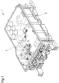
Figure 2 is an exploded view of the battery charger ofFigure 1 ; -
Figure 3 is a view of an IMS (Insulated Metal Substrate) electronic board of the battery charger according to the invention; -
Figure 4 shows a detail of the IMS electronic board ofFigure 3 . - With particular reference to these illustrations, reference numeral 1 globally indicates a battery charger for vehicles, in particular of the type that can be installed on board of electric, hybrid or similar vehicles and adapted to recharge the battery of the vehicle.
- The battery charger 1 comprises an
outer container 2, adapted to house and protect the entire electronics of the battery charger itself and adapted to allow the installation and fixing thereof inside the vehicle. - The battery charger 1 comprises an electronic appliance, globally indicated with
reference numeral 3 in the figures, housed inside thecontainer 2, operatively connectable to an electric battery of a vehicle and configured for the recharge of the battery itself. - The battery charger also comprises a
cooling circuit 4 to limit the temperature of theelectronic appliance 3 during the use of the battery charger 1. - For example, the
cooling circuit 4 can be composed of a conventional liquid cooling circuit. - According to the particular but not exclusive embodiment illustrated in the figures, the
cooling circuit 4 is made directly on the bottom of thecontainer 2. - The
electronic appliance 3 comprises at least oneelectronic board 5 provided with an insulated metal substrate (IMS) 5a associated with thecooling circuit 4. - The
electronic board 5 also comprises a layer of electrically insulatingmaterial 5b made on at least one portion of theinsulated metal substrate 5a, and at least oneelectronic circuit 5c made on the layer of electrically insulatingmaterial 5b. Theelectronic appliance 3 may comprise several electronic boards. - For example, with reference to the particular but not limited embodiment shown in the illustrations, the
electronic appliance 3 comprises twoelectronic boards electronic board 5 is of the IMS type. - The
electronic board 5 comprises at least oneconductive metal bar 7 for the transport and distribution of current, electrically connected to theelectronic circuit 5c. - This
conductive metal bar 7 is of the type of a so-called "busbar", used to allow the transport and distribution of high currents to several different points of an electronic board. - The
conductive metal bar 7 is provided with at least one portion arranged in direct contact with at least one surface portion of theelectronic board 5. - In this way, the
conductive metal bar 7 can be cooled and, therefore, maintained at a lower working temperature, during the use of the battery charger 1. In fact, thecooling circuit 4 allows cooling theinsulated metal substrate 5a of theelectronic board 5 and, by heat conduction, allows cooling theconductive metal bar 7. - The positioning of the
conductive metal bar 7 directly onto theelectronic board 5, together with the fact that theconductive metal bar 7 is cooled by means of thecooling circuit 4, by heat conduction with theinsulated metal substrate 5a of the electronic board itself, allow for the use of aconductive metal bar 7 of reduced size compared to the bars of known type. - In particular, the
conductive metal bar 7 is provided with a lower surface arranged in direct contact with at least one surface portion of theelectronic board 5. - Preferably, the
conductive metal bar 7 is substantially plate-shaped and comprises an upper surface opposite the lower surface associated with theelectronic board 5. - In addition, the
conductive metal bar 7 preferably has a substantially elongated shape. - Different shapes of the
conductive metal bar 7 cannot however be ruled out. - With reference to the particular embodiment shown in the illustrations, the
electronic board 5 comprises a plurality ofconductive metal bars 7, arranged at different portions of the electronic board itself and adapted to connect different points. - Each
conductive metal bar 7 extends over at least one portion of theelectronic board 5, on the layer of electrically insulatingmaterial 5b. - Advantageously, each
conductive metal bar 7 comprises electric coupling and connection means 8 of at least one electric connecting element. The electric connecting element, not shown in the figures, can be composed e.g. of a special cable adapted to carry a predefined electrical current on theconductive metal bar 7. - For example, the electric coupling and connection means 8 are composed of an electric terminal made at at least one portion of the
conductive metal bar 7. - As shown in the figures, the terminal extends from the upper surface of the
conductive metal bar 7. - As an example, the
electronic board 5 described above is used inside a battery charger 1 for electric vehicles. - The use cannot however be ruled out in different applications of an electronic board similar to the
electronic board 5 described above, provided with at least oneconductive metal bar 7. - It has in practice been ascertained that the described invention achieves the intended objects.
- In particular, the fact is underlined that the electronic board according to the invention is small in size and, at the same time, simple and quick to assemble.
- In fact, the positioning of the conductive metal bar directly on the electronic board, together with the fact that the conductive metal bar is cooled by means of the cooling circuit, by heat conduction with the insulated metal substrate of the electronic board itself, allow the use of a conductive metal bar of reduced size compared to the bars of known type.
- In addition, the conductive metal bar used, precisely because it is cooled down, allows the maintenance of an ideal working temperature in an effective manner.
Claims (8)
- Electronic board (5) comprising an insulated metal substrate (5a) associable with a cooling circuit (4), a layer of electrically insulating material (5b) made on at least one portion of said insulated metal substrate (5a), at least one electronic circuit (5c) made on said layer of electrically insulating material (5b), and at least one conductive metal bar (7) for the transport and the distribution of current, electrically connected to said electronic circuit (5c) and provided with a lower surface arranged in direct contact with at least one surface portion of said electronic board (5), characterized in that said lower surface extends over at least one portion of said electronic board (5), on said layer of electrically insulating material (5b), for the cooling of said conductive metal bar (7) by means of said cooling circuit (4).
- Electronic board (5) according to claim 1, characterized by the fact that said conductive metal bar (7) is substantially plate-shaped.
- Electronic board (5) according to one or more of the preceding claims, characterized by the fact that said conductive metal bar (7) comprises an upper surface opposite said lower surface associated with said electronic board (5).
- Electronic board (5) according to one or more of the preceding claims, characterized by the fact that said conductive metal bar (7) has a substantially elongated shape.
- Electronic board (5) according to one or more of the preceding claims, characterized by the fact that said conductive metal bar (7) comprises electric coupling and connection means (8) of at least one electric connecting element.
- Electronic board (5) according to claim 5, characterized by the fact that said electric coupling and connection means (8) comprise at least one electric terminal (8) made at at least one portion of said conductive metal bar (7).
- Electronic board (5) according to claim 6, characterized by the fact that said at least one electric terminal (8) extends from said upper surface of the conductive metal bar (7).
- Battery charger (1) for vehicles, comprising at least one outer container (2), at least one electronic appliance (3) housed inside said container (2), operatively connectable to an electric battery of a vehicle and configured for the recharge of said battery, and at least one cooling circuit (4) of said electronic appliance (3), characterized in that said electronic appliance (3) comprises at least one electronic board (5) according to one or more of the preceding claims.
Applications Claiming Priority (2)
| Application Number | Priority Date | Filing Date | Title |
|---|---|---|---|
| IT102018000007387A IT201800007387A1 (en) | 2018-07-20 | 2018-07-20 | CHARGER FOR VEHICLES |
| PCT/IB2019/056170 WO2020016833A1 (en) | 2018-07-20 | 2019-07-18 | Battery charger for vehicles |
Publications (2)
| Publication Number | Publication Date |
|---|---|
| EP3824704A1 EP3824704A1 (en) | 2021-05-26 |
| EP3824704B1 true EP3824704B1 (en) | 2025-06-18 |
Family
ID=63834555
Family Applications (1)
| Application Number | Title | Priority Date | Filing Date |
|---|---|---|---|
| EP19772856.1A Active EP3824704B1 (en) | 2018-07-20 | 2019-07-18 | Battery charger for vehicles |
Country Status (6)
| Country | Link |
|---|---|
| US (1) | US11700715B2 (en) |
| EP (1) | EP3824704B1 (en) |
| JP (1) | JP7496346B2 (en) |
| CN (1) | CN110733361B (en) |
| IT (1) | IT201800007387A1 (en) |
| WO (1) | WO2020016833A1 (en) |
Families Citing this family (5)
| Publication number | Priority date | Publication date | Assignee | Title |
|---|---|---|---|---|
| CN111404216B (en) * | 2020-03-10 | 2023-03-31 | 安徽潜川动力锂电科技有限公司 | Prevent falling intelligent treasured that charges |
| CN113246764B (en) * | 2021-05-12 | 2023-03-24 | 美达电器(重庆)有限公司 | Charging machine |
| USD1101671S1 (en) * | 2022-09-08 | 2025-11-11 | Harbinger Motors Inc. | Battery pack |
| CN118358398A (en) * | 2023-01-18 | 2024-07-19 | 华为数字能源技术有限公司 | On-board power supply device and vehicle |
| CN118596931B (en) * | 2024-06-18 | 2024-12-03 | 南京金龙客车制造有限公司 | Fast charging device and new energy heavy-duty truck tractor |
Citations (1)
| Publication number | Priority date | Publication date | Assignee | Title |
|---|---|---|---|---|
| US20060039127A1 (en) * | 2004-08-19 | 2006-02-23 | Distributed Power, Inc. | High power density insulated metal substrate based power converter assembly with very low BUS impedance |
Family Cites Families (25)
| Publication number | Priority date | Publication date | Assignee | Title |
|---|---|---|---|---|
| ES2187280B1 (en) * | 2001-06-28 | 2004-08-16 | Lear Automotive (Eeds) Spain, S.L. | PRINTED CIRCUIT PLATE WITH ISOLATED METAL SUBSTRATE WITH INTEGRATED REFRIGERATION SYSTEM. |
| US7187548B2 (en) * | 2002-01-16 | 2007-03-06 | Rockwell Automation Technologies, Inc. | Power converter having improved fluid cooling |
| US6865080B2 (en) * | 2002-01-16 | 2005-03-08 | Rockwell Automation Technologies, Inc. | Compact fluid cooled power converter supporting multiple circuit boards |
| DE102006028675B4 (en) * | 2006-06-22 | 2008-08-21 | Siemens Ag | Cooling arrangement for arranged on a support plate electrical components |
| JP4452952B2 (en) * | 2007-06-20 | 2010-04-21 | 日立オートモティブシステムズ株式会社 | Power converter |
| JP4452953B2 (en) * | 2007-08-09 | 2010-04-21 | 日立オートモティブシステムズ株式会社 | Power converter |
| JP2011124244A (en) * | 2008-04-24 | 2011-06-23 | Denki Kagaku Kogyo Kk | Insulating metal base circuit board and hybrid integrated circuit module using the same |
| JP5238380B2 (en) * | 2008-07-07 | 2013-07-17 | 本田技研工業株式会社 | Solder bonding structure of power supply device and bonding method thereof |
| DE102008048005B3 (en) * | 2008-09-19 | 2010-04-08 | Infineon Technologies Ag | Power semiconductor module arrangement and method for producing a power semiconductor module arrangement |
| DE102009053998A1 (en) * | 2009-11-19 | 2011-05-26 | Still Gmbh | Inverter, in particular multi-phase three-phase converter |
| WO2011083578A1 (en) * | 2010-01-08 | 2011-07-14 | トヨタ自動車株式会社 | Semiconductor module |
| JP5646242B2 (en) * | 2010-07-28 | 2014-12-24 | Fdkトワイセル株式会社 | Circuit board equipment |
| JP2013099119A (en) * | 2011-10-31 | 2013-05-20 | Sanyo Electric Co Ltd | Battery charger |
| ITMO20110325A1 (en) * | 2011-12-15 | 2013-06-16 | Meta System Spa | PROCEDURE FOR THE REALIZATION OF BATTERY CHARGERS FOR VEHICLES AND BATTERY CHARGERS AS AVAILABLE |
| JP6135543B2 (en) * | 2014-02-19 | 2017-05-31 | 株式会社デンソー | Power supply |
| JP6260566B2 (en) * | 2015-03-25 | 2018-01-17 | 株式会社オートネットワーク技術研究所 | Circuit structure |
| DE102015113873B3 (en) * | 2015-08-21 | 2016-07-14 | Semikron Elektronik Gmbh & Co. Kg | Power electronic assembly with capacitor device |
| JP2017127097A (en) * | 2016-01-13 | 2017-07-20 | 株式会社デンソー | Controller built-in dynamo-electric machine |
| JP7145075B2 (en) * | 2016-02-24 | 2022-09-30 | ヒタチ・エナジー・スウィツァーランド・アクチェンゲゼルシャフト | Power modules based on multilayer circuit boards |
| JP6814612B2 (en) * | 2016-06-02 | 2021-01-20 | 矢崎総業株式会社 | Vehicle grounding structure |
| DE102016112777B4 (en) * | 2016-07-12 | 2021-03-18 | Semikron Elektronik Gmbh & Co. Kg | Power semiconductor device |
| KR102638979B1 (en) * | 2016-12-21 | 2024-02-22 | 현대자동차주식회사 | Power module, manufacture method of power module and Vehicle having the same |
| DE102017003854A1 (en) * | 2017-04-20 | 2018-10-25 | Leopold Kostal Gmbh & Co. Kg | Housing for an electrical or electronic device |
| IT201700070324A1 (en) * | 2017-06-23 | 2018-12-23 | Meta System Spa | ELECTRONIC POWER EQUIPMENT FOR ELECTRIC OR HYBRID CARS AND ITS APPLICATION PROCEDURE |
| US10394292B1 (en) * | 2018-06-11 | 2019-08-27 | Microsoft Technology Licensing, Llc | Cryogenic computing system with thermal management using a metal preform |
-
2018
- 2018-07-20 IT IT102018000007387A patent/IT201800007387A1/en unknown
-
2019
- 2019-03-08 CN CN201910173921.0A patent/CN110733361B/en active Active
- 2019-07-18 EP EP19772856.1A patent/EP3824704B1/en active Active
- 2019-07-18 US US17/261,808 patent/US11700715B2/en active Active
- 2019-07-18 WO PCT/IB2019/056170 patent/WO2020016833A1/en not_active Ceased
- 2019-07-18 JP JP2021502753A patent/JP7496346B2/en active Active
Patent Citations (1)
| Publication number | Priority date | Publication date | Assignee | Title |
|---|---|---|---|---|
| US20060039127A1 (en) * | 2004-08-19 | 2006-02-23 | Distributed Power, Inc. | High power density insulated metal substrate based power converter assembly with very low BUS impedance |
Also Published As
| Publication number | Publication date |
|---|---|
| CN110733361A (en) | 2020-01-31 |
| EP3824704A1 (en) | 2021-05-26 |
| IT201800007387A1 (en) | 2020-01-20 |
| US20210298209A1 (en) | 2021-09-23 |
| JP7496346B2 (en) | 2024-06-06 |
| JP2021530957A (en) | 2021-11-11 |
| WO2020016833A1 (en) | 2020-01-23 |
| US11700715B2 (en) | 2023-07-11 |
| CN110733361B (en) | 2025-02-14 |
Similar Documents
| Publication | Publication Date | Title |
|---|---|---|
| EP3824704B1 (en) | Battery charger for vehicles | |
| US11276536B2 (en) | Power relay assembly | |
| US10128722B2 (en) | Electrical connection structure, terminal structure, and vehicle | |
| US10179557B2 (en) | Multi-voltage on-board electrical system and multilayer cable for different voltage levels | |
| US11451118B2 (en) | Conductor arrangement and transportable electrical drive device | |
| US20090066289A1 (en) | Battery charger with a planar bus | |
| US20180219305A1 (en) | High power module interfaces | |
| EP2792045B1 (en) | Procedure for the manufacture of battery chargers for vehicles and battery chargers thus obtainable | |
| US10103521B2 (en) | Electrical power distribution plate comprising a protected distribution bar | |
| US20150331058A1 (en) | Voltage detecting device | |
| US20170149288A1 (en) | Wireless transmission device | |
| KR101901134B1 (en) | Capacitor case structure | |
| KR20160040865A (en) | Bus bar mounted on metal printed circuit board in vehicle | |
| US20190009684A1 (en) | Power system | |
| CN106465534A (en) | High current switch | |
| CN109841980B (en) | Voltage converter, male electrical connector and manufacturing method thereof | |
| EP3296174B1 (en) | Vehicular control device | |
| EP3824701B1 (en) | Battery charger for vehicles and relative realization process | |
| JP2022190189A (en) | switching device | |
| JP2018076013A5 (en) | ||
| EP3056834B1 (en) | Electrical heating device | |
| US20250164317A1 (en) | Temperature measuring system for power semiconductors arranged on a base plate of an inverter | |
| WO2018054453A1 (en) | An electrical junction box | |
| CN117730630A (en) | Voltage conversion system and method for manufacturing such voltage conversion system | |
| KR20250176535A (en) | Battery Module, Method for Providing Monitoring Functionality for the Same, Battery System and Electric Vehicle |
Legal Events
| Date | Code | Title | Description |
|---|---|---|---|
| STAA | Information on the status of an ep patent application or granted ep patent |
Free format text: STATUS: UNKNOWN |
|
| STAA | Information on the status of an ep patent application or granted ep patent |
Free format text: STATUS: THE INTERNATIONAL PUBLICATION HAS BEEN MADE |
|
| PUAI | Public reference made under article 153(3) epc to a published international application that has entered the european phase |
Free format text: ORIGINAL CODE: 0009012 |
|
| STAA | Information on the status of an ep patent application or granted ep patent |
Free format text: STATUS: REQUEST FOR EXAMINATION WAS MADE |
|
| 17P | Request for examination filed |
Effective date: 20210218 |
|
| AK | Designated contracting states |
Kind code of ref document: A1 Designated state(s): AL AT BE BG CH CY CZ DE DK EE ES FI FR GB GR HR HU IE IS IT LI LT LU LV MC MK MT NL NO PL PT RO RS SE SI SK SM TR |
|
| DAV | Request for validation of the european patent (deleted) | ||
| DAX | Request for extension of the european patent (deleted) | ||
| STAA | Information on the status of an ep patent application or granted ep patent |
Free format text: STATUS: EXAMINATION IS IN PROGRESS |
|
| 17Q | First examination report despatched |
Effective date: 20230515 |
|
| P01 | Opt-out of the competence of the unified patent court (upc) registered |
Effective date: 20230527 |
|
| GRAP | Despatch of communication of intention to grant a patent |
Free format text: ORIGINAL CODE: EPIDOSNIGR1 |
|
| STAA | Information on the status of an ep patent application or granted ep patent |
Free format text: STATUS: GRANT OF PATENT IS INTENDED |
|
| INTG | Intention to grant announced |
Effective date: 20240906 |
|
| GRAS | Grant fee paid |
Free format text: ORIGINAL CODE: EPIDOSNIGR3 |
|
| GRAA | (expected) grant |
Free format text: ORIGINAL CODE: 0009210 |
|
| STAA | Information on the status of an ep patent application or granted ep patent |
Free format text: STATUS: THE PATENT HAS BEEN GRANTED |
|
| AK | Designated contracting states |
Kind code of ref document: B1 Designated state(s): AL AT BE BG CH CY CZ DE DK EE ES FI FR GB GR HR HU IE IS IT LI LT LU LV MC MK MT NL NO PL PT RO RS SE SI SK SM TR |
|
| REG | Reference to a national code |
Ref country code: GB Ref legal event code: FG4D |
|
| REG | Reference to a national code |
Ref country code: CH Ref legal event code: EP |
|
| REG | Reference to a national code |
Ref country code: DE Ref legal event code: R096 Ref document number: 602019071282 Country of ref document: DE |
|
| REG | Reference to a national code |
Ref country code: CH Ref legal event code: EP |
|
| REG | Reference to a national code |
Ref country code: IE Ref legal event code: FG4D |
|
| PG25 | Lapsed in a contracting state [announced via postgrant information from national office to epo] |
Ref country code: FI Free format text: LAPSE BECAUSE OF FAILURE TO SUBMIT A TRANSLATION OF THE DESCRIPTION OR TO PAY THE FEE WITHIN THE PRESCRIBED TIME-LIMIT Effective date: 20250618 |
|
| PGFP | Annual fee paid to national office [announced via postgrant information from national office to epo] |
Ref country code: DE Payment date: 20250901 Year of fee payment: 7 |
|
| REG | Reference to a national code |
Ref country code: LT Ref legal event code: MG9D |
|
| PG25 | Lapsed in a contracting state [announced via postgrant information from national office to epo] |
Ref country code: NO Free format text: LAPSE BECAUSE OF FAILURE TO SUBMIT A TRANSLATION OF THE DESCRIPTION OR TO PAY THE FEE WITHIN THE PRESCRIBED TIME-LIMIT Effective date: 20250918 Ref country code: GR Free format text: LAPSE BECAUSE OF FAILURE TO SUBMIT A TRANSLATION OF THE DESCRIPTION OR TO PAY THE FEE WITHIN THE PRESCRIBED TIME-LIMIT Effective date: 20250919 |
|
| PGFP | Annual fee paid to national office [announced via postgrant information from national office to epo] |
Ref country code: IT Payment date: 20250917 Year of fee payment: 7 |
|
| PG25 | Lapsed in a contracting state [announced via postgrant information from national office to epo] |
Ref country code: BG Free format text: LAPSE BECAUSE OF FAILURE TO SUBMIT A TRANSLATION OF THE DESCRIPTION OR TO PAY THE FEE WITHIN THE PRESCRIBED TIME-LIMIT Effective date: 20250618 |
|
| PGFP | Annual fee paid to national office [announced via postgrant information from national office to epo] |
Ref country code: GB Payment date: 20250909 Year of fee payment: 7 |
|
| PG25 | Lapsed in a contracting state [announced via postgrant information from national office to epo] |
Ref country code: HR Free format text: LAPSE BECAUSE OF FAILURE TO SUBMIT A TRANSLATION OF THE DESCRIPTION OR TO PAY THE FEE WITHIN THE PRESCRIBED TIME-LIMIT Effective date: 20250618 |
|
| PGFP | Annual fee paid to national office [announced via postgrant information from national office to epo] |
Ref country code: FR Payment date: 20250829 Year of fee payment: 7 |
|
| PG25 | Lapsed in a contracting state [announced via postgrant information from national office to epo] |
Ref country code: RS Free format text: LAPSE BECAUSE OF FAILURE TO SUBMIT A TRANSLATION OF THE DESCRIPTION OR TO PAY THE FEE WITHIN THE PRESCRIBED TIME-LIMIT Effective date: 20250918 |
|
| REG | Reference to a national code |
Ref country code: NL Ref legal event code: MP Effective date: 20250618 |
|
| PG25 | Lapsed in a contracting state [announced via postgrant information from national office to epo] |
Ref country code: LV Free format text: LAPSE BECAUSE OF FAILURE TO SUBMIT A TRANSLATION OF THE DESCRIPTION OR TO PAY THE FEE WITHIN THE PRESCRIBED TIME-LIMIT Effective date: 20250618 |
|
| PG25 | Lapsed in a contracting state [announced via postgrant information from national office to epo] |
Ref country code: NL Free format text: LAPSE BECAUSE OF FAILURE TO SUBMIT A TRANSLATION OF THE DESCRIPTION OR TO PAY THE FEE WITHIN THE PRESCRIBED TIME-LIMIT Effective date: 20250618 |
|
| PG25 | Lapsed in a contracting state [announced via postgrant information from national office to epo] |
Ref country code: PT Free format text: LAPSE BECAUSE OF FAILURE TO SUBMIT A TRANSLATION OF THE DESCRIPTION OR TO PAY THE FEE WITHIN THE PRESCRIBED TIME-LIMIT Effective date: 20251020 |
|
| REG | Reference to a national code |
Ref country code: AT Ref legal event code: MK05 Ref document number: 1805414 Country of ref document: AT Kind code of ref document: T Effective date: 20250618 |
|
| PG25 | Lapsed in a contracting state [announced via postgrant information from national office to epo] |
Ref country code: IS Free format text: LAPSE BECAUSE OF FAILURE TO SUBMIT A TRANSLATION OF THE DESCRIPTION OR TO PAY THE FEE WITHIN THE PRESCRIBED TIME-LIMIT Effective date: 20251018 |
|
| REG | Reference to a national code |
Ref country code: DE Ref legal event code: R081 Ref document number: 602019071282 Country of ref document: DE Owner name: META ELECTRONICS S.R.L., ALTO RENE TERME, IT Free format text: FORMER OWNER: META SYSTEM S.P.A., REGGIO EMILIA, IT Ref country code: DE Ref legal event code: R081 Ref document number: 602019071282 Country of ref document: DE Owner name: META ELECTRONICS S.R.L., ALTO RENO TERME, IT Free format text: FORMER OWNER: META SYSTEM S.P.A., REGGIO EMILIA, IT |
|
| PG25 | Lapsed in a contracting state [announced via postgrant information from national office to epo] |
Ref country code: AT Free format text: LAPSE BECAUSE OF FAILURE TO SUBMIT A TRANSLATION OF THE DESCRIPTION OR TO PAY THE FEE WITHIN THE PRESCRIBED TIME-LIMIT Effective date: 20250618 Ref country code: SM Free format text: LAPSE BECAUSE OF FAILURE TO SUBMIT A TRANSLATION OF THE DESCRIPTION OR TO PAY THE FEE WITHIN THE PRESCRIBED TIME-LIMIT Effective date: 20250618 |
|
| PG25 | Lapsed in a contracting state [announced via postgrant information from national office to epo] |
Ref country code: CZ Free format text: LAPSE BECAUSE OF FAILURE TO SUBMIT A TRANSLATION OF THE DESCRIPTION OR TO PAY THE FEE WITHIN THE PRESCRIBED TIME-LIMIT Effective date: 20250618 |
|
| PG25 | Lapsed in a contracting state [announced via postgrant information from national office to epo] |
Ref country code: PL Free format text: LAPSE BECAUSE OF FAILURE TO SUBMIT A TRANSLATION OF THE DESCRIPTION OR TO PAY THE FEE WITHIN THE PRESCRIBED TIME-LIMIT Effective date: 20250618 |
|
| PG25 | Lapsed in a contracting state [announced via postgrant information from national office to epo] |
Ref country code: EE Free format text: LAPSE BECAUSE OF FAILURE TO SUBMIT A TRANSLATION OF THE DESCRIPTION OR TO PAY THE FEE WITHIN THE PRESCRIBED TIME-LIMIT Effective date: 20250618 |
|
| PG25 | Lapsed in a contracting state [announced via postgrant information from national office to epo] |
Ref country code: SK Free format text: LAPSE BECAUSE OF FAILURE TO SUBMIT A TRANSLATION OF THE DESCRIPTION OR TO PAY THE FEE WITHIN THE PRESCRIBED TIME-LIMIT Effective date: 20250618 Ref country code: RO Free format text: LAPSE BECAUSE OF FAILURE TO SUBMIT A TRANSLATION OF THE DESCRIPTION OR TO PAY THE FEE WITHIN THE PRESCRIBED TIME-LIMIT Effective date: 20250618 |
|
| PG25 | Lapsed in a contracting state [announced via postgrant information from national office to epo] |
Ref country code: ES Free format text: LAPSE BECAUSE OF FAILURE TO SUBMIT A TRANSLATION OF THE DESCRIPTION OR TO PAY THE FEE WITHIN THE PRESCRIBED TIME-LIMIT Effective date: 20250618 |
|
| REG | Reference to a national code |
Ref country code: GB Ref legal event code: 732E Free format text: REGISTERED BETWEEN 20260108 AND 20260114 |
|
| REG | Reference to a national code |
Ref country code: CH Ref legal event code: H13 Free format text: ST27 STATUS EVENT CODE: U-0-0-H10-H13 (AS PROVIDED BY THE NATIONAL OFFICE) Effective date: 20260224 |
|
| PG25 | Lapsed in a contracting state [announced via postgrant information from national office to epo] |
Ref country code: LU Free format text: LAPSE BECAUSE OF NON-PAYMENT OF DUE FEES Effective date: 20250718 |
|
| REG | Reference to a national code |
Ref country code: BE Ref legal event code: MM Effective date: 20250731 |
|
| PG25 | Lapsed in a contracting state [announced via postgrant information from national office to epo] |
Ref country code: MC Free format text: LAPSE BECAUSE OF FAILURE TO SUBMIT A TRANSLATION OF THE DESCRIPTION OR TO PAY THE FEE WITHIN THE PRESCRIBED TIME-LIMIT Effective date: 20250618 |
|
| PG25 | Lapsed in a contracting state [announced via postgrant information from national office to epo] |
Ref country code: DK Free format text: LAPSE BECAUSE OF FAILURE TO SUBMIT A TRANSLATION OF THE DESCRIPTION OR TO PAY THE FEE WITHIN THE PRESCRIBED TIME-LIMIT Effective date: 20250618 |
|
| PG25 | Lapsed in a contracting state [announced via postgrant information from national office to epo] |
Ref country code: BE Free format text: LAPSE BECAUSE OF NON-PAYMENT OF DUE FEES Effective date: 20250731 |
|
| REG | Reference to a national code |
Ref country code: DE Ref legal event code: R081 Ref document number: 602019071282 Country of ref document: DE Owner name: META ELECTRONICS S.R.L., ALTO RENO TERME, IT Free format text: FORMER OWNER: META ELECTRONICS S.R.L., ALTO RENE TERME, BO, IT |
|
| PG25 | Lapsed in a contracting state [announced via postgrant information from national office to epo] |
Ref country code: CH Free format text: LAPSE BECAUSE OF NON-PAYMENT OF DUE FEES Effective date: 20250731 |
|
| PLBE | No opposition filed within time limit |
Free format text: ORIGINAL CODE: 0009261 |
|
| STAA | Information on the status of an ep patent application or granted ep patent |
Free format text: STATUS: NO OPPOSITION FILED WITHIN TIME LIMIT |
|
| REG | Reference to a national code |
Ref country code: CH Ref legal event code: L10 Free format text: ST27 STATUS EVENT CODE: U-0-0-L10-L00 (AS PROVIDED BY THE NATIONAL OFFICE) Effective date: 20260430 |