EP3824321B1 - Systems and methods for detecting a subsurface event - Google Patents
Systems and methods for detecting a subsurface event Download PDFInfo
- Publication number
- EP3824321B1 EP3824321B1 EP19838238.4A EP19838238A EP3824321B1 EP 3824321 B1 EP3824321 B1 EP 3824321B1 EP 19838238 A EP19838238 A EP 19838238A EP 3824321 B1 EP3824321 B1 EP 3824321B1
- Authority
- EP
- European Patent Office
- Prior art keywords
- subsurface
- data set
- fiber optic
- optic data
- event
- Prior art date
- Legal status (The legal status is an assumption and is not a legal conclusion. Google has not performed a legal analysis and makes no representation as to the accuracy of the status listed.)
- Active
Links
Images








Classifications
-
- E—FIXED CONSTRUCTIONS
- E21—EARTH OR ROCK DRILLING; MINING
- E21B—EARTH OR ROCK DRILLING; OBTAINING OIL, GAS, WATER, SOLUBLE OR MELTABLE MATERIALS OR A SLURRY OF MINERALS FROM WELLS
- E21B47/00—Survey of boreholes or wells
- E21B47/003—Determining well or borehole volumes
-
- E—FIXED CONSTRUCTIONS
- E21—EARTH OR ROCK DRILLING; MINING
- E21B—EARTH OR ROCK DRILLING; OBTAINING OIL, GAS, WATER, SOLUBLE OR MELTABLE MATERIALS OR A SLURRY OF MINERALS FROM WELLS
- E21B47/00—Survey of boreholes or wells
- E21B47/09—Locating or determining the position of objects in boreholes or wells, e.g. the position of an extending arm; Identifying the free or blocked portions of pipes
-
- E—FIXED CONSTRUCTIONS
- E21—EARTH OR ROCK DRILLING; MINING
- E21B—EARTH OR ROCK DRILLING; OBTAINING OIL, GAS, WATER, SOLUBLE OR MELTABLE MATERIALS OR A SLURRY OF MINERALS FROM WELLS
- E21B47/00—Survey of boreholes or wells
- E21B47/12—Means for transmitting measuring-signals or control signals from the well to the surface, or from the surface to the well, e.g. for logging while drilling
-
- E—FIXED CONSTRUCTIONS
- E21—EARTH OR ROCK DRILLING; MINING
- E21B—EARTH OR ROCK DRILLING; OBTAINING OIL, GAS, WATER, SOLUBLE OR MELTABLE MATERIALS OR A SLURRY OF MINERALS FROM WELLS
- E21B47/00—Survey of boreholes or wells
- E21B47/12—Means for transmitting measuring-signals or control signals from the well to the surface, or from the surface to the well, e.g. for logging while drilling
- E21B47/13—Means for transmitting measuring-signals or control signals from the well to the surface, or from the surface to the well, e.g. for logging while drilling by electromagnetic energy, e.g. radio frequency
- E21B47/135—Means for transmitting measuring-signals or control signals from the well to the surface, or from the surface to the well, e.g. for logging while drilling by electromagnetic energy, e.g. radio frequency using light waves, e.g. infrared or ultraviolet waves
-
- G—PHYSICS
- G01—MEASURING; TESTING
- G01H—MEASUREMENT OF MECHANICAL VIBRATIONS OR ULTRASONIC, SONIC OR INFRASONIC WAVES
- G01H9/00—Measuring mechanical vibrations or ultrasonic, sonic or infrasonic waves by using radiation-sensitive means, e.g. optical means
- G01H9/004—Measuring mechanical vibrations or ultrasonic, sonic or infrasonic waves by using radiation-sensitive means, e.g. optical means using fibre optic sensors
-
- G—PHYSICS
- G01—MEASURING; TESTING
- G01V—GEOPHYSICS; GRAVITATIONAL MEASUREMENTS; DETECTING MASSES OR OBJECTS; TAGS
- G01V1/00—Seismology; Seismic or acoustic prospecting or detecting
- G01V1/16—Receiving elements for seismic signals; Arrangements or adaptations of receiving elements
- G01V1/18—Receiving elements, e.g. seismometer, geophone or torque detectors, for localised single point measurements
- G01V1/189—Combinations of different types of receiving elements
-
- G—PHYSICS
- G01—MEASURING; TESTING
- G01V—GEOPHYSICS; GRAVITATIONAL MEASUREMENTS; DETECTING MASSES OR OBJECTS; TAGS
- G01V1/00—Seismology; Seismic or acoustic prospecting or detecting
- G01V1/22—Transmitting seismic signals to recording or processing apparatus
- G01V1/226—Optoseismic systems
Definitions
- the present disclosure relates to systems and methods for detecting a given subsurface event in a subsurface volume of interest.
- US 2013/0215717 A1 which relates to integrated passive and active seismic surveying using multiple arrays.
- the system is initially set up by recording seismic data with a buried array installation while shooting a significant portion of the 3D surface seismic survey.
- the 3D surface seismic survey provides the following data: shallow 3D VSP data from the buried arrays; P-wave and converted wave data for the area covered by the buried array that benefits from the planned data integration processing effort; and microseismic data and associated analysis.
- the method may further include receiving a sensor data set of the given subsurface event.
- the sensor data set may include responses detected by a sensor.
- a given sensor data specifies parameter values of parameters as a function of position within the subsurface volume of interest.
- the method may further include refining the event location of the subsurface event using the sensor data set.
- refining the event location of the subsurface event using the sensor data set may include identifying a set of potential locations based on the refined subsurface fiber optic data set. Refining the event location of the subsurface event using the sensor data set may also include deriving directionality from sensor data set based on polarization analysis. The sensor data set includes responses detected by a subsurface geophone. Refining the event location of the subsurface event using the sensor data set may further include selecting the correct location among the potential locations using the refined subsurface fiber optic data set and the sensor data set.
- refining the event location of the subsurface event using the sensor data set may include identifying a set of potential locations based on the refined subsurface fiber optic data set. Refining the event location of the subsurface event using the sensor data set may also include deriving multiple location semblance values based on traveltimes to one or more sensors corresponding to the sensor data set. The sensor data set includes responses detected by a surface geophone. Refining the event location of the subsurface event using the sensor data set may include refining the event location from the set of potential locations based on one of the multiple location semblance values.
- the method may further include generating a digital seismic image that represents the refined subsurface fiber optic data set using visual effects to depict at least a portion of the parameter values in the refined subsurface fiber optic data set and at least a portion of the parameter values in the sensor data set as a function of position within the subsurface volume of interest; and displaying the digital seismic image on a graphical user interface.
- the fiber optic apparatus forms a distributed acoustic sensing cable.
- the senor includes one or more of a fiber optic apparatus or a geophone.
- a first set of models may include a multiple signal classification model, and a semblance-based model.
- the method may further include generating sets of probability maps of a given subsurface event by applying the first set of models to the constrained subsurface fiber optic data sets.
- a given set of probability maps includes a first probability map based on applying the multiple signal classification model and a second probability map based on applying the semblance-based model.
- the method may further include limiting the constrained subsurface fiber optic data set based on whether a semblance value of the given set of probability maps surpasses a threshold semblance value to generate a limited subsurface fiber optic data set.
- the method may further include determining whether semblance values of the refined subsurface fiber optic data set surpasses a refined threshold value.
- the sensor data set is used to derive a wavespeed structure.
- an origin time may be updated by applying one or more of the subsurface fiber optic data set, the constrained subsurface fiber optic data set, and the refined subsurface fiber optic data set.
- estimating an origin time based on the event location may include obtaining a velocity model; and estimating an origin time based on arrival times corresponding to the refined subsurface fiber optic data set and propagation times based on the velocity model and the event location.
- the velocity model is based on well data.
- the origin time is a given arrival time minus a corresponding propagation time.
- refining the event location of the subsurface event using the sensor data set may include identifying a set of potential locations based on the refined subsurface fiber optic data set. Refining the event location of the subsurface event using the sensor data set may further include deriving directionality from sensor data set based on polarization analysis. The sensor data set includes responses detected by a subsurface geophone. Refining the event location of the subsurface event using the sensor data set may further include selecting the correct location among the potential locations using the refined subsurface fiber optic data set and the sensor data set.
- the present invention relates to a system configured for detecting a given subsurface event in a subsurface volume of interest.
- the system includes one or more physical computer processors configured by machine-readable instructions
- the one or more processors are configured to receive a subsurface fiber optic data set of the given subsurface event.
- the subsurface fiber optic data set includes responses detected by a fiber optic apparatus.
- a given subsurface fiber optic data specifies parameter values of parameters as a function of position in the subsurface volume of interest.
- the processor(s) may be configured to receive a sensor data set of the given subsurface event.
- the sensor data set includes responses detected by one or more sensors.
- a given sensor data may specify parameter values of parameters as a function of position within the subsurface volume of interest.
- the one or more processors are configured to constrain the subsurface fiber optic data set based on a given parameter value of a given parameter within a certain range to generate a constrained subsurface fiber optic data set.
- the one or more processors are configured to use sets of models to refine the constrained subsurface fiber optic data set to generate a refined subsurface fiber optic data set.
- the processor(s) may be configured to generate a moment tensor corresponding to the given subsurface event using the refined subsurface fiber optic data set and the sensor data set.
- the processor(s) may be configured to generate a digital seismic image that represents the moment tensor and the refined subsurface fiber optic data set using visual effects to depict at least a portion of the moment tensor and at least a portion of the parameter values in the refined subsurface fiber optic data set, such as event origin time and location within the subsurface volume of interest.
- the processor(s) may be configured to display the digital seismic image on a graphical user interface.
- Hydrocarbon exploration processes, hydrocarbon recovery processes, or any combination thereof may be performed on a "subsurface volume of interest".
- the "subsurface volume of interest” refers to practically anything under a surface.
- the subsurface volume of interest may be practically anything under a terrestrial surface (e.g., practically anything under a land surface), practically anything under a seafloor, etc.
- a water column may be above the subsurface volume of interest, for example, in marine hydrocarbon exploration, in marine hydrocarbon recovery, etc.
- the subsurface volume of interest may be onshore in some implementations.
- the subsurface volume of interest may be offshore, with shallow water or deep water above the subsurface volume of interest, in some implementations.
- the subsurface volume of interest may include faults, fractures, overburdens, underburdens, salts, salt welds, rocks, sands, sediments, pore space, etc.
- the subsurface volume of interest may include practically any geologic point(s) or volume(s) of interest (such as a survey area).
- the subsurface volume of interest may also include hydrocarbons, such as liquid hydrocarbons (also known as oil or petroleum), gas hydrocarbons (e.g., natural gas), solid hydrocarbons (e.g., asphaltenes or waxes), a combination of liquid hydrocarbons, gas hydrocarbons, and solid hydrocarbons, etc.
- hydrocarbons such as liquid hydrocarbons (also known as oil or petroleum), gas hydrocarbons (e.g., natural gas), solid hydrocarbons (e.g., asphaltenes or waxes), a combination of liquid hydrocarbons, gas hydrocarbons, and solid hydrocarbons, etc.
- Light crude oil, medium oil, heavy crude oil, and extra heavy oil, as defined by the American Petroleum Institute (API) gravity are examples of hydrocarbons.
- examples of hydrocarbons are many, and may include, oil, natural gas, kerogen, bitumen, clathrates (also referred to as hydrates), etc.
- the subsurface volume of interest may be known to include hydrocarbons in some implementation
- the subsurface volume of interest may also include at least one wellbore.
- at least one wellbore may be drilled into the subsurface volume of interest in order to confirm the presence of hydrocarbons.
- at least one preexisting wellbore into the subsurface volume of interest or at least one new wellbore drilled into the subsurface may be used to recover the hydrocarbons.
- the hydrocarbons may be recovered from the entire subsurface or from a portion of the subsurface.
- the subsurface may be divided up into one or more hydrocarbon zones, and hydrocarbons may be recovered from each desired hydrocarbon zone. In some implementations, one or more of hydrocarbon zones may even be shut in to increase hydrocarbon recovery from a hydrocarbon zone that is not shut in.
- the hydrocarbons may be recovered (sometimes referred to as produced) from the subsurface volume of interest using primary recovery (e.g., by relying on pressure to recover the hydrocarbons), secondary recovery (e.g., by using water injection (also referred to as waterflooding) or gas injection to recover hydrocarbons), enhanced oil recovery (EOR), or any combination thereof.
- primary recovery e.g., by relying on pressure to recover the hydrocarbons
- secondary recovery e.g., by using water injection (also referred to as waterflooding) or gas injection to recover hydrocarbons
- EOR enhanced oil recovery
- the term “enhanced oil recovery” refers to techniques for increasing the amount of hydrocarbons that may be extracted from the volume of interest.
- Enhanced oil recovery may also be referred to as improved oil recovery or tertiary oil recovery.
- Secondary recovery may also just be referred to as enhanced oil recovery.
- the hydrocarbons may also be recovered from the subsurface volume of interest using fracturing.
- fracturing may include fracturing using electrodes, fracturing using fluid (oftentimes referred to as hydraulic fracturing), etc.
- hydraulic fracturing may entail preparing an injection fluid (oftentimes referred to a fracturing fluid) and injecting that fracturing fluid into the wellbore at a sufficient rate and pressure to open existing fractures and/or create fractures in the subsurface volume of interest. The fractures permit hydrocarbons to flow more freely into the wellbore.
- Fracturing may be performed onshore, offshore, or any combination thereof.
- the fracturing fluid may be prepared on-site to include at least proppants.
- the proppants such as sand or other particles, are meant to hold the fractures open so that hydrocarbons can more easily flow to the wellbore.
- the fracturing fluid and the proppants may be blended together using at least one blender.
- the fracturing fluid may also include other components in addition to the proppants.
- the wellbore and the subsurface volume of interest proximate to the wellbore are in fluid communication (e.g., via perforations), and the fracturing fluid with the proppants is injected into the wellbore through a wellhead of the wellbore using at least one pump (oftentimes called a fracturing pump).
- the fracturing fluid with the proppants is injected at a sufficient rate and pressure to open existing fractures and/or create fractures in the subsurface volume of interest. As fractures become sufficiently wide to allow proppants to flow into those fractures, proppants in the fracturing fluid are deposited in those fractures during injection of the fracturing fluid.
- the fracturing fluid is removed by flowing or pumping it back out of the wellbore so that the fracturing fluid does not block the flow of hydrocarbons to the wellbore.
- the hydrocarbons will typically enter the same wellbore from the subsurface volume of interest and go up to the surface for further processing.
- the fracturing may be performed in stages in some implementations.
- the equipment to be used in preparing and injecting the fracturing fluid may be dependent on the components of the fracturing fluid, the proppants, the wellbore, the subsurface volume of interest, etc.
- the term "fracturing apparatus" is meant to represent any tank(s), mixer(s), blender(s), pump(s), manifold(s), line(s), valve(s), fluid(s), fracturing fluid component(s), proppants, and other equipment and techniques related to preparing the fracturing fluid, injecting the fracturing fluid, and fracturing.
- the hydrocarbons may also be recovered from the subsurface volume of interest using radio frequency (RF) heating.
- RF radio frequency
- at least one radio frequency antenna may be utilized to increase the temperature of hydrocarbons, such as heavy oil, to reduce viscosity.
- the hydrocarbons with lower viscosity may then be produced from the subsurface volume of interest with an improved flow rate.
- radio frequency heating apparatus is meant to represent any antenna(s), fluid(s), and other equipment and techniques related to radio frequency heating.
- hydrocarbon recovery processes may also be utilized to recover the hydrocarbons.
- hydrocarbon recovery processes may also include stimulation or other treatment.
- radio frequency heating may be used in combination with at least one other recovery process, such as, but not limited to, steam flooding.
- non-hydrocarbon items may include connate water, brine, tracers, items used in enhanced oil recovery or other hydrocarbon recovery processes, items from other types of treatments (e.g., gels used in conformance control), etc.
- each subsurface volume of interest may have a variety of characteristics, such as petrophysical rock properties, reservoir fluid properties, reservoir conditions, or any combination thereof.
- each subsurface volume of interest may be associated with one or more of: temperature, porosity, permeability, water composition, mineralogy, hydrocarbon type, hydrocarbon quantity, reservoir location, pressure, etc.
- shale gas shale oil
- tight gas tight oil
- tight carbonate carbonate
- vuggy carbonate unconventional (e.g., a rock matrix with an average pore size less than 1 micrometer), diatomite, geothermal, coalbed methane, a methane hydrate containing subsurface volume of interest, a mineral containing subsurface volume of interest, a metal containing subsurface volume of interest, a subsurface volume of interest having a permeability in the range of 0.01 microdarcy to 10 millidarcy, a subsurface volume of interest having a permeability in the range of 10 millidarcy to 40,000 millidarcy, etc.
- subsurface volume of interest may be used synonymously with the term “reservoir” or “subsurface reservoir” or “subsurface region of interest” or “formation” or “subsurface formation.”
- the subsurface volume of interest may also include a reservoir, a formation, or any combination thereof.
- the terms “subsurface volume of interest,” “hydrocarbons,” and the like are not limited to any description or configuration described herein.
- Wellbore refers to a single hole, usually cylindrical, that is drilled into the subsurface volume of interest for hydrocarbon exploration, hydrocarbon recovery, or any combination thereof.
- the wellbore is surrounded by the subsurface volume of interest and the wellbore may be in fluidic communication with the subsurface volume of interest (e.g., via perforations).
- the wellbore may also be in fluidic communication with the surface, such as a surface facility that may include oil/gas/water separators, gas compressors, storage tanks, pumps, gauges, pipelines, etc.
- the wellbore may be used for injection in some implementations.
- the wellbore may be used for production in some implementations.
- the wellbore may be used for fracturing in some implementations.
- the wellbore may be used for a single function, such as only injection, in some implementations.
- the wellbore may be used for a plurality of functions, such as both injection and production in some implementations.
- the use of the wellbore may also be changed, for example, a particular wellbore may be turned into an injection wellbore after a different previous use.
- the wellbore may be drilled amongst existing wellbores as an infill wellbore.
- a plurality of wellbores e.g., tens to hundreds of wellbores
- the hydrocarbons may be swept from a single injection wellbore towards at least one production wellbore and then up towards the surface for further processing.
- the wellbore may have vertical, horizontal, or combination trajectories.
- the wellbore may be a vertical wellbore, a horizontal wellbore, a multilateral wellbore, an inclined wellbore, a slanted wellbore, etc.
- the wellbore may include a "build section.” "Build section" refers to practically any section of a wellbore where the deviation is changing. As an example, the deviation is changing when the wellbore is curving.
- the build section is the curved section between the vertical section of the horizontal wellbore and the horizontal section of the horizontal wellbore.
- Wellbores that are not horizontal wellbores may also include build sections.
- inclined or slanted wellbores may each include a build section.
- the wellbore may include a plurality of components, such as, but not limited to, a casing, a liner, a tubing string, a heating element, a sensor, a packer, a screen, a gravel pack, etc.
- the "casing” refers to a steel pipe cemented in place during the wellbore construction process to stabilize the wellbore.
- the "liner” refers to any string of casing in which the top does not extend to the surface but instead is suspended from inside the previous casing.
- the "tubing string” or simply “tubing” is made up of a plurality of tubulars (e.g., tubing, tubing joints, pup joints, etc.) connected together.
- the tubing string is lowered into the casing or the liner for injecting a fluid into the subsurface volume of interest, producing a fluid from the subsurface volume of interest, or any combination thereof.
- the casing may be cemented in place, with the cement positioned in the annulus between the subsurface volume of interest and the outside of the casing.
- the wellbore may also include any completion hardware that is not discussed separately. If the wellbore is drilled offshore, for example, the wellbore may include some of the previous components plus other components such as a riser and others.
- the wellbore may also include equipment to control fluid flow into the wellbore, control fluid flow out of the wellbore, or any combination thereof.
- each wellbore may include a wellhead, a BOP, chokes, valves, or other control devices. These control devices may be located on the surface, under the surface (e.g., downhole in the wellbore), or any combination thereof. In some implementations, the same control devices may be used to control fluid flow into and out of the wellbore, but different control devices may even be used. In some implementations, the rate of flow of fluids through the wellbore may depend on the fluid handling capacities of the surface facility that is in fluidic communication with the wellbore. The control devices may also be utilized to control the pressure profile of the wellbore.
- control apparatus is meant to represent any wellhead(s), BOP(s), choke(s), valve(s), fluid(s), and other equipment and techniques related to controlling fluid flow into and out of the wellbore.
- the wellbore may be drilled into the subsurface volume of interest using practically any drilling technique and equipment known in the art, such as geosteering, directional drilling, etc.
- drilling the wellbore may include using a tool such as a drilling tool.
- the drilling tool may include a drill bit and a drill string.
- Drilling fluid such as drilling mud, may be used while drilling in order to cool the drill tool and remove cuttings.
- Other tools may also be used while drilling or after drilling, such as measurement-while-drilling (MWD) tools, seismic-while-drilling (SWD) tools, wireline tools, logging-while-drilling (LWD) tools, other downhole tools, etc.
- MWD measurement-while-drilling
- SWD seismic-while-drilling
- LWD logging-while-drilling
- the drill string and the drill bit are removed, and then the casing, the tubing, etc. may be installed according to the design of the wellbor
- the equipment to be used in drilling the wellbore may be dependent on the design of the wellbore, the subsurface volume of interest, the hydrocarbons, etc.
- the term “drilling apparatus” is meant to represent any drill bit(s), drill string(s), drilling fluid(s), and other equipment and techniques related to drilling the wellbore.
- wellbore may be used synonymously with the terms “borehole,” “well,” or “well bore.”
- wellbore is not limited to any description or configuration described herein.
- proximate is defined as “near”. If item A is proximate to item B, then item A is near item B. For example, in some implementations, item A may be in contact with item B. For example, in some implementations, there may be at least one barrier between item A and item B such that item A and item B are near each other, but not in contact with each other.
- the barrier may be a fluid barrier, a non-fluid barrier (e.g., a structural barrier), or any combination thereof. Both scenarios are contemplated within the meaning of the term "proximate.”
- if may be construed to mean “when” or “upon” or “in response to determining” or “in accordance with a determination” or “in response to detecting,” that a stated condition precedent is true, depending on the context.
- phrase “if it is determined [that a stated condition precedent is true]” or “if [a stated condition precedent is true]” or “when [a stated condition precedent is true]” may be construed to mean “upon determining” or “in response to determining” or “in accordance with a determination” or “upon detecting” or “in response to detecting” that the stated condition precedent is true, depending on the context.
- the item described by this phrase could include only a component of type C. In some implementations, the item described by this phrase could include a component of type A and a component of type B. In some implementations, the item described by this phrase could include a component of type A and a component of type C. In some implementations, the item described by this phrase could include a component of type B and a component of type C. In some implementations, the item described by this phrase could include a component of type A, a component of type B, and a component of type C. In some implementations, the item described by this phrase could include two or more components of type A (e.g., A1 and A2).
- the item described by this phrase could include two or more components of type B (e.g., B1 and B2). In some implementations, the item described by this phrase could include two or more components of type C (e.g., C1 and C2). In some implementations, the item described by this phrase could include two or more of a first component (e.g., two or more components of type A (A1 and A2)), optionally one or more of a second component (e.g., optionally one or more components of type B), and optionally one or more of a third component (e.g., optionally one or more components of type C).
- a first component e.g., two or more components of type A (A1 and A2)
- a second component e.g., optionally one or more components of type B
- a third component e.g., optionally one or more components of type C.
- the item described by this phrase could include two or more of a first component (e.g., two or more components of type B (B1 and B2)), optionally one or more of a second component (e.g., optionally one or more components of type A), and optionally one or more of a third component (e.g., optionally one or more components of type C).
- the item described by this phrase could include two or more of a first component (e.g., two or more components of type C (C1 and C2)), optionally one or more of a second component (e.g., optionally one or more components of type A), and optionally one or more of a third component (e.g., optionally one or more components of type B).
- stages that are not order dependent may be reordered and other stages may be combined or broken out. While some reordering or other groupings are specifically mentioned, others will be obvious to those of ordinary skill in the art and so do not present an exhaustive list of alternatives. Moreover, it should be recognized that the stages could be implemented in hardware, firmware, software, or any combination thereof.
- Fiber optics is a growing field for subsurface exploration. While fiber optic apparatuses may provide dense sampling rates of subsurface data for subsurface events, multiple challenges are presented. Fiber optic apparatuses, for example fiber optic distribution acoustic sensing (DAS) systems, may measure one component of the strain or strain rate, losing other relevant information. Amplitude variation, phase rotation, and polarity flip may also be more common due to the behavior of strain and strain rate, for example. In addition, signal to noise ratios of fiber optic data may require extensive preprocessing.
- DAS fiber optic distribution acoustic sensing
- Systems and methods disclosed herein are configured to detect subsurface events using fiber optic apparatuses.
- the raw data from a fiber optic apparatus may be preprocessed to improve signal to noise ratio and remove other artifacts to generate a subsurface fiber optic data set.
- Sensor data including, for example, other fiber optic data from a different source, data from 3C geophones, and/or data from subsurface and/or surface geophones, may also be received.
- the subsurface fiber optic data set is constrained based on a given parameter value within a certain range to generate a constrained subsurface fiber optic data set. Sets of models are used to refine the constrained subsurface fiber optic data set to generate a refined subsurface fiber optic data set.
- the refined subsurface fiber optic data set may be validated and, in some implementations, steps may be repeated to improve the location and origin times.
- steps may be repeated to improve the location and origin times.
- a moment tensor may be generated corresponding to the subsurface event.
- a digital seismic image may be generated of the moment tensor.
- the digital seismic image may be displayed in a graphical user interface.
- the digital seismic image may improve hydrocarbon exploration and improve hydrocarbon production.
- the digital seismic image may provide details of the subsurface that were illustrated poorly or not at all in traditional seismic images.
- the digital seismic image may better delineate where different features begin, end, or any combination thereof.
- the digital seismic image may illustrate faults more accurately.
- the digital seismic image may be utilized in hydrocarbon exploration and hydrocarbon production for decision making and control.
- the digital seismic image may be utilized to steer a tool (e.g., drilling tool) to drill a wellbore.
- a drilling tool may be steered to drill one or more wellbores to produce the clathrate deposit or steered to avoid the clathrate deposit depending on the desired outcome.
- Steering the tool may include drilling around or avoiding certain subsurface features (e.g., faults, salt diapirs, shale diapirs, shale ridges, pockmarks, buried channels, gas chimneys, shallow gas pockets, and slumps), drilling through certain subsurface features (e.g., clathrate deposit), or any combination thereof depending on the desired outcome.
- certain subsurface features e.g., faults, salt diapirs, shale diapirs, shale ridges, pockmarks, buried channels, gas chimneys, shallow gas pockets, and slumps
- subsurface features e.g., clathrate deposit
- the digital seismic image may be utilized to select completions, components, fluids, etc. for a wellbore.
- Some recovery techniques and devices, amongst many options, are provided in the following: U.S. Patent No. 9,777,563 , U.S. Patent No. 7,812,203 , U.S. Patent App. Pub. No. 2008/0102000 , U.S. Patent No. 7,964,150 , U.S. Patent No. 8,201,626 , and U.S. Patent No. 7,537,058 .
- Seismic Source A "seismic source” (or simply “source”) refers to practically anything that generates seismic excitations.
- the seismic excitations may be seismic waves, such as sound waves.
- the seismic excitations may sometimes be referred to as subsurface events.
- a seismic source may be active or passive.
- An active seismic source is activated to send at least one seismic wave.
- the active seismic source may be an air gun, a water gun, a vibrator, a marine vibrator, etc.
- a passive seismic source passively sends at least one seismic wave.
- the passive seismic source may be an ocean wave, a passing ship, a storm, an interfering seismic survey, environmental energy, etc.
- the seismic source may be practically any seismic source that is compatible with a fiber optic apparatus (discussed further hereinbelow).
- a plurality of seismic sources generate seismic excitations.
- the plurality of seismic sources may be of the same type, or alternatively, the plurality of seismic sources may be a combination of different types.
- one or more seismic sources may be in the subsurface volume of interest (e.g., downhole in a wellbore drilled into the subsurface volume of interest), one or more seismic sources may be outside of the subsurface volume of interest (e.g., on a terrestrial surface using a vibroseis truck or on an aquatic surface deployed on or pulled by a sea surface vessel), or any combination thereof.
- the sea surface vessel may be a ship, a platform, a FPSO (Floating, Production, Storage, and Offloading vessel), Automated Surface Vehicle (AS), etc.
- the equipment to be used in installing a seismic source may be dependent on the type of the seismic source, location where the seismic source is to be installed, whether the installation is temporary or more permanent, etc.
- the term "seismic source installation apparatus" is meant to represent any truck(s), towline(s), sea surface vessel(s), float(s), and other equipment and techniques related to installing a seismic source. Regardless of the location of the seismic sources, the seismic excitations in the subsurface volume of interest, outside of the subsurface volume of interest, or any combination thereof may be used in some implementations.
- hydrocarbon recovery processes such as, but not limited to, a fracturing process may generate seismic excitations.
- a fracturing apparatus may be utilized to open existing fractures and/or create fractures in the subsurface volume of interest. Opening the existing fractures and/or creating the fractures may cause seismic excitations in the subsurface volume of interest.
- a "seismic sensor” refers to practically anything that detects responses associated with seismic excitations.
- a seismic sensor is a geophone, such as a one component (1C) or a three component (3C) geophone.
- One implementation of a seismic sensor is an accelerometer.
- One implementation of a seismic sensor is a hydrophone.
- One implementation of the seismic sensor is a fiber optic (FO) apparatus.
- the FO apparatus may be configured to perform at least distributed acoustic sensing (DAS).
- DAS distributed temperature sensing
- DTS distributed temperature sensing
- a plurality of seismic sensors may detect responses associated with seismic excitations.
- the plurality of seismic sensors may be of the same type, or alternatively, the plurality of seismic sensors may be a combination of different types.
- at least two FO apparatuses with each configured to perform at least DAS, may utilized.
- at least one FO apparatus configured to perform at least DAS and at least one other seismic sensor (e.g., a hydrophone, a geophone, etc.) may be utilized.
- the at least one seismic sensor may be co-located with the at least one FO apparatus, may be in a wellbore, and/or may be otherwise located in the subsurface volume of interest.
- the at least one seismic sensor may be located based on finite difference modeling, an analytical Green Tensor, moment tensor information, subsurface fiber optic data set, and/or other information.
- An acquisition design may be generated to determine the appropriate acquisition geometry for the at least one seismic sensor.
- the acquisition design may simulate responses from each component of the moment tensor for any acquisition geometry. Based on this information, a linear inverse equation may be derived and a corresponding Hessian matrix including eigenvalues and a condition number indicates how well the inverse problem is constrained or how suitable a given acquisition geometry is for inverting the moment tensor. By comparing eigenvalues and/or condition numbers of different Hessian matrix from different acquisition geometries, acquisition geometries can be selected to apply in a given subsurface volume of interest.
- a single entity may perform an embodiment consistent with this disclosure. It is also contemplated that a plurality of entities may perform an embodiment consistent with the disclosure. For example, it is contemplated that a particular entity may install a fiber optic apparatus and one or more sensors , process data from the fiber optic apparatus and the one or more sensors, and detect subsurface events with the data. For example, it is also contemplated that a particular entity receives data (raw and/or processed) from the fiber optic apparatus and the one or more sensors, and one or more other entities installs the fiber optic apparatus and the one or more sensors, as well as processes the data from the fiber optic apparatus and the one or more sensors.
- one or more seismic sensors may be in the subsurface volume of interest (e.g., downhole in a wellbore drilled into the subsurface volume of interest, trench or dug hole in the subsurface volume of interest), one or more seismic sensors may be outside of the subsurface volume of interest (e.g., in a trench or dug hole outside of the subsurface volume of interest), or any combination thereof.
- the equipment to be used in installing a seismic sensor may be dependent on the type of the seismic sensor, location where the seismic sensor is to be installed, whether the installation is temporary or more permanent, etc.
- the term "seismic sensor installation apparatus" is meant to represent any clamp(s), strap(s), reel(s), and other equipment and techniques related to installing a seismic sensor. Regardless of the location of the seismic sensors, responses associated with seismic excitations in the subsurface volume of interest may be detected, responses associated with seismic excitations outside of the subsurface volume of interest may be detected, or any combination thereof may be used in some implementations.
- one implementation of this apparatus comprises a FO cable
- this disclosure will discuss the FO cable in great detail.
- the implementations herein may be performed with practically any FO apparatus configured to perform the claimed functions.
- the FO apparatus may comprise at least one FO sensor or sensing portion (e.g., a single point FO sensor arrangement, a multi-point FO sensor arrangement, distributed sensing arrangement, a multiplexed arrangement, etc.).
- the FO apparatus may include practically any arrangement of FO sensors or sensing portions to perform at least DAS or similar to DAS.
- the FO cable may be configured to perform at least DAS.
- the FO cable may be configured to perform DPS, DTS, or any combination thereof in addition to DAS.
- a previously installed FO cable may already be configured to perform DAS (and optionally DPS and optionally DTS), and this previously installed FO cable may be utilized herein.
- a new FO cable configured to perform DAS (and optionally DPS and optionally DTS) may be installed.
- the equipment and techniques to be used to install the FO cable may depend on whether the FO cable is to be installed in a permanent, pumpable, or temporary manner, as well as the location where the FO cable is to be installed.
- the seismic sensor installation apparatus may be utilized to install the FO cable.
- the FO cable may include one or more scatterers.
- the FO cable may include one or more diffractors.
- the FO cable may include one or more reflectors.
- the FO cable includes one or more optical fibers used for DAS. In one implementation, an unmodified, substantially continuous length of standard optical fiber may be used, requiring little or no modification or preparation for use as a DAS optical fiber.
- the FO cable configured for DAS may optionally include one or more optical fibers for DPS and may optionally include one or more optical fibers for DTS.
- the FO cable may include at least one optical fiber that may be, but is not limited to: one or more optical fibers used for DAS, one or more optical fibers for DPS, one or more optical fibers used for DTS, or any combination thereof.
- the optical fibers may include multimode optical fibers, single mode optical fibers, etc.
- Each DAS optical fiber of the FO cable may be optically interrogated by one or more input pulses to provide (but do not have to be) substantially continuous sensing of strain activity along its length.
- an interrogator e.g., an interrogator on land or a marinized interrogator in an aquatic environment
- the DAS optical fiber may be either single-mode or multimode.
- Optical pulses are launched into the DAS optical fiber and the radiation backscattered from within the DAS optical fiber is detected and analyzed.
- Backscattering e.g., Rayleigh backscattering
- the DAS optical fiber By analyzing the radiation backscattered within the DAS optical fiber, the DAS optical fiber can effectively be divided into a plurality of sensing portions or points which may be (but do not have to be) substantially contiguous. Seismic excitations from seismic sources, hydrocarbon recovery processes such as fracturing, etc. cause a variation in the amount of backscatter (e.g., Rayleigh backscatter) from that portion. This variation can be detected and analyzed and used to give a measure of the acoustic spectrum intensity of disturbance of the DAS optical fiber at that portion.
- the term "acoustic" may be taken to mean any type of wave, including seismic waves and sounds from sub-Hertz to 20 KHz.
- Raman backscattering may be utilized for temperature measurements from one or more DTS optical fibers.
- Fibre Bragg Grating FBG may be utilized for pressure measurements from one or more DPS optical fibers.
- the FO cable may be coupled to an apparatus that comprises an interrogator.
- the interrogator may be on land or on a sea surface vessel.
- the interrogator contains opto-electronic components.
- the interrogator provides light (e.g., laser light) into the FO cable and receives the backscatter energy from the FO cable.
- the fracturing process causes strain
- the strain causes the backscatter energy from the FO cable.
- the interrogator may also convert the backscatter energy into arrival times and generates subsurface fiber optic data set that includes the arrival times.
- the subsurface fiber optic data set may be sent from the interrogator to at least one system, such as at least one computing system, for (1) receiving a subsurface fiber optic data set, (2) receiving a sensor data set, (3) constraining the subsurface fiber optic data set, (4) using models to refine the constrained subsurface fiber optic data set, (5) generating a moment tensor, (6) generating a digital seismic image.
- all of this functionality (1)-(6) may be performed at a first computing system on land or on the sea surface (e.g., on a sea surface vessel).
- the subsurface fiber optic data set may be sent from the interrogator to a first computing system on the sea surface, such as on a sea surface vessel.
- the subsurface fiber optic data set may then be sent from the first computing system to a second computing system on land for functionality (2)-(6).
- the subsurface fiber optic data set may be stored at the first computing system, the second computing system, or both.
- the subsurface fiber optic data set may be sent from the interrogator to a first computing system on the sea surface, such as on a sea surface vessel, for partial processing of the subsurface fiber optic data set.
- the partially processed subsurface fiber optic data set may be sent from the first computing system to a second computing system on land for functionality (2)-(6).
- the subsurface fiber optic data set may be stored at the first computing system, the second computing system, or both.
- the subsurface fiber optic data set may be sent from the interrogator to a first computing system on the sea surface, such as on a sea surface vessel, and the subsurface fiber optic data set may be accessed by one or more users from a second computing system on land (e.g., a user logs on remotely to the first computing system).
- the functionality (2)-(6) is performed on the subsurface fiber optic data set at the first computing system on the sea surface by the one or more users without sending the subsurface fiber optic data set to the second computing system on land.
- the subsurface fiber optic data set may also be partially processed at the first computing system on the sea surface before the one or more users on land accesses it.
- the subsurface fiber optic data set (before processing, during processing, or after processing) may be combined with other data (e.g., ground truth data, core data, etc.).
- the functionality described for the interrogator may be divided among multiple components that are on the sea surface, under the sea surface, on land, or any combination thereof.
- the functionality described for the interrogator may use other components, for example, to aid in underwater optical communication, to aid communication from under the sea surface with the sea surface, etc.
- additional elements may include marinized (i.e. designed to be submerged in a marine environment) junction boxes, a marinized data download system, wet mate connectors to allow cable splits for floating and/or weighted cables, etc.
- Use of an underwater optical communication system may also provide highest bandwidth data transfer over short range between a marinized data download device and a mobile underwater vehicle (ROV or AUV).
- modifications may include using high power light emitting diodes (LED) as the transmitter and a receiver, and using photo multiplexors to increase sensitivity, or alternately using focused underwater laser.
- LED light emitting diodes
- There may also be additional subsea infrastructure with a FO junction box, an interrogator (e.g., marinized interrogator), or any combination thereof.
- An interrogator e.g., marinized interrogator
- a plurality of interrogators may be used in some implementations.
- DAS, DTS, and DPS interrogators may be different, and each of these may be used depending on the implementation.
- the functionality described for the first computing system and/or the second computing system may be divided among multiple components that are on the sea surface, under the sea surface, on land, or any combination thereof.
- the functionality described for the first computing system and/or the second computing system may use other components.
- the FO cable includes at least one optical fiber that may be surrounded by at least one protective layer to shield the at least one optical fiber against the environment.
- One implementation of the FO cable comprises a capillary tubing (also referred to as capillary tube) to house the at least one optical fiber.
- the capillary tubing may be filled with a fluid, e.g., a hydrogen scavenging gel, an inert heat transfer fluid, or an inert gas.
- the filling fluid is a gel designed to scavenge hydrogen and protect the at least one optical fiber from hydrogen darkening. The gel also helps to support the weight of the at least one optical fiber within the capillary tubing.
- the capillary tubing is filled with an inert gas such as nitrogen to avoid exposure of the at least one optical fiber to water or hydrogen, thereby minimizing any hydrogen-induced darkening of the at least one optical fiber during oilfield operations.
- an inert gas such as nitrogen
- a single capillary tubing is used, which contains a plurality of optical fibers.
- multiple capillary tubings may be used, with each capillary tubing containing one or more optical fibers.
- a variety of installation options may be utilized: permanent, pumpable, or temporary.
- the pumpable option two capillary tubings are used to enable pumping fluid to be pumped down the capillary tubing and returned to the surface.
- a turnaround sub with a U-tube geometry is used at the deepest wellbore placement to join the two capillary tubings and enable pumping.
- the viscous drag force of the pumped fluid on the at least one optical fiber enables recovery and replacement.
- the pumping of the at least one optical fiber may occur in a factory, controlled surface environment, or at the wellsite with the at least one optical fiber in the wellbore.
- the pumpable option may be used if one or two optical fibers are used.
- the pumpable option allows the at least one optical fiber to be recovered and replaced should it experience hydrogen darkening.
- At least one optical fiber is installed inside a capillary tubing in a factory or controlled environment. If a permanently installed optical fiber becomes damaged due to hydrogen darkening or thermal degradation, the recourse is a complete replacement.
- the permanent and pumpable options may strap or clamp the capillary tubing to the outside of casing, liners, and tubing, or installed inside a coiled tubing instrument tube.
- At least one optical fiber is run into a wellbore off a reeling system into the tubing or into a coiled tubing instrument tube.
- the coiled tubing instrument tube could be free hanging in the tubing-casing annulus or strapped to the tubing, casing, or liner.
- the temporary deployable optical fiber may use a small diameter FIMT (fiber in metal tube) with an outside diameter of 0.23 to 0.38 cm (0.09 to 0.15 inches), which is reinforced with fiber glass, polyproylene, polyethylene, carbon fiber, or any combinations of the foregoing which encases and protects the FIMT.
- This temporary option is designed to be run in and out of many wellbores and installed for a few hours to a few weeks to acquire data.
- installation options may depend on whether a wellbore is existing or new.
- installation may be inside the liner or casing on the tubing or coiled tubing to take advantage of the preexisting structure.
- installation may be either inside or outside the liner or casing with trade-offs between cost, risk, etc.
- the capillary tubing may be attached to the outer surface of the tubing with a plurality of clamps, or any known method for coupling conduits. Further, in some implementations, it should be appreciated that the capillary tubing need not be coupled to the tubing, but it may be coupled to any other conduits in the wellbore or the casing / liner itself, or it may be integral with the casing / liner, e.g., the capillary tubing may be positioned in the annulus, clamped / strapped / fastened to any of the tubing, inside the tubing, the liner, the casing, the instrument coiled tubing, or any combination thereof.
- the installation scheme that is chosen may depend upon whether the wellbore is new or preexisting, components of the wellbore, etc.
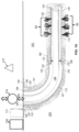
- FIG. 1A illustrates a schematic sectional view of a subsurface volume of interest in fluidic communication with a wellbore during a fracturing process in accordance with one implementation. Fractures may be detected using a seismic sensor 177 and a FO apparatus 178 as discussed herein.
- the wellbore 105 is a horizontal wellbore.
- the wellbore 105 includes a vertical section 110, the build section 112, and a horizontal section 115.
- the area between the vertical section 110 and the horizontal section 115 is referred to as the heel and the area towards the end of the horizontal section 115 is referred to as the toe.
- unconventional reservoirs may be produced using horizontal wellbores, such as the wellbore 105.
- the wellbore 105 may be drilled with drilling apparatus 113 through the subsurface volume of interest 101.
- the drilling apparatus 113 may include a drill bit, a drill string, etc.
- the drilling apparatus 113 may be utilized to drill at least one other wellbore, drill at least one other track, or any combination thereof.
- the wellbore 105 may be cemented as illustrated by cement 106.
- the wellbore 105 may include a surface casing 120 along a portion of the wellbore 105, a production casing 125 along a portion of the wellbore 105, and a liner 130 (e.g., a slotted liner) attached by at least one liner hanger 132.
- a liner 130 e.g., a slotted liner
- the wellbore 105 may also include a tubing 145 within the surface casing 120, the production casing 125, and the liner 130.
- the tubing 145 includes a plurality of tubulars tubing joints, pup joints, packers (e.g., may include centralizers), etc.
- the end of the tubing 145 (e.g., at the toe) includes a bull plug 150. At least one packer 170 may be located in an annulus 169 between the tubing 145 and the liner 130.
- a control apparatus 114 may control fluid flow into the wellbore 105. The control apparatus 114 may also control fluid flow out of the wellbore 105.
- the wellbore 105 may be utilized for fracturing, including opening existing fractures and/or creating fractures, that lead to fractures 50 in the subsurface volume of interest 101.
- a perforation apparatus may be deployed in a desired location in the wellbore 105 to generate perforations through one or more layers of the wellbore 105, and then a fracturing apparatus 116 may be used to open and/or create the fractures 50. Fracturing may occur in stages in some implementations.
- the hydrocarbons from the subsurface volume of interest 101 flow into the wellbore 105 through one or more of the fractures 50 and up towards the surface 140 for refining, transporting, etc.
- Subsurface events such as opening existing fractures and/or creating fractures in a subsurface volume of interest 101, generate seismic excitations.
- the FO cable 178 detects the strain resulting from the seismic excitations and the seismic sensor 177 detects strain and/or subsurface energy that may be received by geophones, hydrophones, and/or other seismic sensors.
- the seismic excitations such as caused by the fracturing, may be detected in real-time or near real-time.
- the seismic sensor 177 and the FO cable 178 may be installed with a seismic sensor installation apparatus 179 (illustrated in FIGS. 1B, 2A-1, 2A-2 , 2B-1, 2B-2 , 2C-1, 2C-2 , 2D-1, and 2D-2 ).
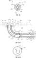
- FIG. 1B illustrates an expanded view, in cross-section, of the capillary tubing 180.
- the capillary tubing 180 is one implementation of the FO cable 178, however, those of ordinary skill in the art will appreciate that there are other designs and the appended claims are not limited to any disclosed implementations.
- the capillary tubing 180 may be a portion of the length or the entire length of the wellbore 105.
- the outer diameter of the capillary tubing 180 may be about 0.23 cm to about 0.95 cm (about 1/8 inches to about 3/8 inches).
- the outer diameter of the capillary tubing 180 may be about 0.635 cm (1/4 inches).
- the dimensions of the capillary tubing 180 may vary as long as the responses to seismic excitations may be detected to generate subsurface fiber optic data set 334.
- the capillary tubing 180 includes a core 185 comprised of a first protective layer that is typically of an Inconel ® or Incoloy ® alloy 25, a stainless steel, or any combination thereof with at least one optical fiber 186 with at least one sensing portion inside the core 185.
- a first protective layer typically of an Inconel ® or Incoloy ® alloy 25, a stainless steel, or any combination thereof
- the optical fibers 186 is a DAS optical fiber, but other sensing capabilities, such as DPS, may be available in some implementations.
- the optical fibers 186 may have high temperature coatings and coating combinations, including polyimide, high temperature acrylates, silicone-PFA, hermetic carbon, or any combination thereof to prevent hydrogen darkening.
- the core 185 may be filled with fluid, and the fluid surrounds each optical fiber 186.
- the fluid may be a gel or inert gas as discussed hereinabove.
- the inner diameter of the core 185 may be about 0.127 cm to about 0.254 cm (about 0.05 inches to about 0.10 inches).
- the combination of the first protective layer and the optical fiber(s) is commonly referred to as a FIMT or fiber in metal tube.
- the length of the core 185 depends on the length of the capillary tubing 180.
- Adjacent to the core 185 may be an optional second protective layer 187, which may be of a metallic material such as aluminum.
- the diameter of the second protective layer 187 is optional, but may be about 0.254 cm to about 0.508 cm (about 0.10 inches to about 0.20 inches).
- the length of the second protective layer 187 depends on the length of the capillary tubing 180.
- Adjacent to the optional second protective layer 187 may be a third protective layer 188, which may be of a metallic material (e.g., Inconel ® or Incoloy ® alloy 25, a stainless steel, or any combination thereof).
- the diameter of the third protective layer 188 may be about 0.508 cm to about 1.016 cm (about 0.20 inches to about 0.40 inches).
- the length of the third protective layer 188 depends on the length of the capillary tubing 180.
- Adjacent to the third protective layer 188 may be an encapsulation protective layer 189, which is an extruded encapsulation polymer (e.g., polyethylene, polypropolyene, Teflon TM brand, Hypalon TM brand, or any combination thereof).
- the diameter of the encapsulation protective layer 189 may be about 0.635 cm to about 1.905 cm (about 0.25 inches to about 0.75 inches).
- the length of the encapsulation protective layer 189 depends on the length of the capillary tubing 180.
- FIGS. 2A-1 and 2A-2 illustrate an implementation with a hydraulic wet connect at liner top 131 with the capillary tubing 180 being clamped to the tubing 145 above the liner top 131. There may be one or more of the capillary tubing 180. In the implementation of FIGS. 2A-1 and 2A-2 , the capillary tubing 180 may be installed outside of the liner 130 in the horizontal section 115 of the wellbore 105, and clamped on the tubing 145 in the vertical section 110.
- This setup may include at least one packer 170.
- FIGS. 2B-1 and 2B-2 illustrate an implementation in which the capillary tubing 180 may be clamped to the casing, such as the production casing 125. There may be one or more of the capillary tubing 180.
- the installation scheme of FIGS. 2B-1 and 2B-2 is similar to the liner deployed surveillance scheme of FIGS. 2A-1 and 2A-2 . As illustrated, the complete system is installed outside of the casing 125.
- the capillary tubing 180 is clamped to the casing 125 as the casing 125 is installed into the wellbore 105.
- the optical fiber 186 may be retrieved and replaced when designed with the pumpable option.
- a single capillary tubing 180 may be run with single or multiple permanent optical fibers 186.
- the perforations may be shot 180 degrees away from the capillary tubing 180.
- the capillary tubing 180 may be run with 1.27 cm (1/2 inch) steel cables on either side of the 0.635 cm (1/4 inch) capillary tubing 180 to facilitate electro-magnetic orienting of perforating guns.
- This setup may include at least one packer 170.
- FIGS. 2C-1 and 2C-2 illustrate an implementation in which the capillary tubing 180 may be clamped to the tubing 145. There may be one or more of the capillary tubing 180. In one implementation of this scheme, the capillary tubing 180 is only clamped on the tubing 145 and no other component. In another implementation, the capillary tubing 180 may be installed inside the tubing 145. The installation scheme in this setup is flexible, which facilitates the changes in the optical fiber 186 design and specifications. Additionally, the optical fiber 186 and capillary tubing 180 are retrievable. This setup may include at least one packer 170, and the capillary tubing 180 may penetrate through each packer 170.
- FIGS. 2D-1 and 2D-2 illustrate an implementation in which the capillary tubing 180 may be positioned within an instrument coiled tubing 190. There may be one or more of the capillary tubing 180.
- the scheme of FIGS. 2D-1 and 2D-2 is used as a temporary surveillance method (e.g., for a few days) so there is less chance of fiber degradation and capillary tubing corrosion.
- the scheme works best with a larger size of liner 130 or casing 125 to avoid damage to the optical fiber 186 and sticking in the wellbore 105.
- the scheme of FIGS. 2D-1 and 2D-2 is flexible, allowing retrieval of optical fiber 186 / capillary tubing 180. This setup may not include any packers 170.
- the FO cable 178 of each of FIGS. 2A-1, 2A-2 , 2B-1 , 2B-2 , 2C-1 , 2C-2 , 2D-1, and 2D-2 may be coupled to an interrogator 75 by a connection 78, such as a wired connection.
- the interrogator 75 may be coupled to at least one computing system 300 by a connection 76, such as a wired connection or even a wireless connection.
- FIGS. 1A , 1B, 2A-1, 2A-2 , 2B-1, 2B-2 , 2C-1, 2C-2 , 2D-1, and 2D-2 are not necessarily drawn to scale and those of ordinary skill will appreciate that various modifications may be made. For example, dimensions, materials, components, connectors, etc. may be based on compatibility with the conditions on and under the surface 140. Some modifications may also be found in U.S. Patent App. Pub. Nos. 2016/0281471 (Attorney Dkt. No. T-10077) , 2016/0281494 (Attorney Dkt. No. T-10089) , and 2016/0281456 (Attorney Dkt. No. T-10242).
- FIG. 3 illustrates a system 300 configured for detecting a subsurface event using, in accordance with one or more implementations.
- system 300 may include one or more servers 302.
- Server(s) 302 may be configured to communicate with one or more client computing platforms 304 according to a client/server architecture and/or other architectures.
- Client computing platform(s) 304 may be configured to communicate with other client computing platforms via server(s) 302 and/or according to a peer-to-peer architecture and/or other architectures. Users may access system 300 via client computing platform(s) 304.
- Machine-readable instructions 306 may include one or more instruction components.
- the instruction components may include computer program components.
- the instruction components may include one or more of a fiber optic data component 308, a sensor data component 310, a model component 312, a moment tensor component 314, a digital seismic image component 316, and/or other instruction components.
- Fiber optic data component 308 is configured to receive a subsurface fiber optic data set of the given subsurface event using a fiber optic apparatus.
- the fiber optic apparatus may include fiber optic sensors, fiber optic cables, and/or other implementations of fiber optics.
- the fiber optic apparatus may form a distributed acoustic sensing cable.
- a given subsurface fiber optic data specifies parameter values of parameters as a function of position of the fiber optic apparatus located in the subsurface volume of interest.
- Parameters may include original measurements such as strain, strain rate, change in temperature, arrival times, and derived properties such as coherency, semblance, event magnitudes, event locations, origin times, and/or other parameters.
- strain rate in a fiber optic cable may indicate physical deformation to the fiber optic cable with respect to time.
- a subsurface event may include shifting of tectonic plates, movement of subsurface features, human activities generating energy directed into a subsurface region, fault movements, s waves, p waves, and/or other events.
- fiber optic data component 308 may be configured to denoise raw data to generate a subsurface fiber optic data set, remove artifacts from the raw data, or otherwise preprocess the raw data.
- Fourier domain enhancement and/or machine-learning based Wiener filter may be used to preprocess the raw data.
- a short term average (STA) and/or a long term average (LTA) may be used to prefilter the subsurface fiber optic data set.
- the STA and LTA may prefilter the subsurface fiber optic data set to limit the subsurface fiber optic data set to potential subsurface events, or event candidates.
- a STA of the subsurface fiber optic data set divided by a LTA of the subsurface fiber optic data set may be about 1 when no subsurface event is present.
- the STA may vary significantly from the LTA.
- this technique may be used to prefilter the subsurface fiber optic data set to remove data that has a ST/LTA of about 1.
- fiber optic data component 308 is configured to constrain the subsurface fiber optic data set based on a given parameter value of a given parameter within a certain range to generate a constrained subsurface fiber optic data set.
- the given parameter may be the origin time.
- the subsurface fiber optic data set is scanned based on apex times.
- the subsurface fiber optic data set corresponding to the scanned apex times may be the constrained subsurface fiber optic data set.
- the range may be user defined or based on machine learning trained on other subsurface data.
- fiber optic data component 308 may be configured to update the event origin time based on a refined subsurface fiber optic data set, as described herein.
- propagation time may be removed from the updated event location which may align subsurface wiggles of different receivers, or one or more sensors, at an origin time of a given subsurface event.
- the traces corresponding to the refined subsurface fiber optic data set with updated event locations may be steered, stacked, and/or otherwise modified to find a maximum timing point to generate an updated origin time.
- Sensor data component 310 may be configured to receive a sensor data set of the given subsurface event using one or more sensors.
- the one or more sensors may include a fiber optic apparatus, a geophone, a hydrophone, and/or other sensors implemented in, or around, a subsurface volume of interest.
- the one or more sensors may be positioned adjacent to the fiber optic apparatus, in, or around, a well, co-located with the fiber optic apparatus, and/or other locations in the subsurface volume of interest.
- a given subsurface sensor data may specify parameter values of parameters as a function of position within the subsurface volume of interest.
- a depth may be assumed for the subsurface events using the refined subsurface fiber optic data set based on nearby drilling operations, local geological settings or other known events.
- the sensor data set may further refine a location of a subsurface event.
- the sensor data set may be used to provide directionality to the subsurface fiber optic data set.
- the directionality may be obtained by analyzing polarizations of P, SH, and/or SV waves from an event. Examples of such polarization analysis methods may include eigenvalue decomposition, back-azimuth projection, principle component analysis, etc., and may be generally referred to as hodogram analysis in exploration geophysics. It should be appreciated that this list is not exhaustive and other polarization analysis methods may be used.
- a potential refined location of the subsurface event may correspond to a ring around the fiber optic apparatus that detected the subsurface event.
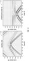
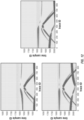
- Each point on the ring may correspond to a potential location of the subsurface event because the subsurface fiber optic data set may not have appropriate directionality and/or polarity to distinguish from which direction the subsurface fiber optic data set is detected, as shown on the left column of FIG. 21 .
- the directionality of arrivals may be obtained, and may be used to determine a unique point on the ring.
- a sensor data set may further refine a location of a subsurface event.
- traveltimes from each potential location to the sensors may be generated and/or obtained. For example, three potential event locations and their corresponding traveltimes in the sensor data set are illustrated in FIG. 21 .
- the correct location leads to traveltimes that match the sensor data set.
- the fitting of the traveltimes and the sensor data set can be evaluated by using semblance analysis.
- an event location that matches both the sensor data and the corresponding subsurface fiber optic data may have the highest semblance in the sensor data set. For example, this may include an x-y-z position in the subsurface volume of interest. It should be appreciated that different semblance values may be selected for different applications.
- the sensor data set may be used to derive a wavespeed structure.
- Model component 312 is configured to use sets of models to refine the constrained subsurface fiber optic data set to generate a refined subsurface fiber optic data set.
- refining the constrained subsurface fiber optic data set includes one or more stages.
- a first set of models represents the first stage of refining the constrained subsurface fiber optic data set.
- a first set of models may include a multiple signal classification model and a semblance-based model. Both the multiple signal classification model and the semblance-based, or coherency-based model may, for example, help determine a location of emitters.
- model component 312 may be configured to generate sets of probability maps of a given subsurface event. Using the first set of models, a first probability map may be generated from the multiple signal classification model, and a second probability map may be generated from the semblance-based model.
- the probability map may be a spatial distribution of the probability of a subsurface event. A spatial location that maximizes the values for the probability maps may be used in the first stage of refining the constrained subsurface fiber optic data set when the corresponding semblance value is greater than a threshold semblance value.
- the semblance value may be a measure of coherence of multiple channels, or, for example, probability maps.
- the threshold semblance value may be user defined or based on machine learning trained on other subsurface data.
- the threshold semblance value may be approximately 0.4 (semblance value ranges from 0 to 1) for a high-quality dataset. But if the signal-to-noise ratio is too low, the threshold may be as low as 0.1 to make sure small events are not excluded at the very beginning.
- the first stage of refining limits the constrained subsurface fiber optic data set into a limited subsurface fiber optic data set.
- the limited subsurface fiber optic data set may include estimated origin times based on the scanned apex times.
- a simple velocity model may be applied to the semblance-based model to improve processing efficiency, as fine-tuning the velocity model at this point may provide minimal improvement in accuracy.
- the RMS velocity may be about 8,000 ft/s. It should be appreciated that different values may be selected based on different wave types and local geological settings.
- channels from a data set may be stacked together. In the case where the data is the same in all channels, semblance would be 1. Where there are differences between the data, semblance would be less than 1. The lowest semblance value may be 0.
- characteristics of the data may be leveraged (e.g., hyperbolic characteristic for velocity in seismic traces). Each data may be corrected for shifts based on the one or more sensors used to detect the data set. The amplitudes of the data can be stacked and normalized. Semblance values may be derived from the data. The highest semblance value may correspond to a data value.
- model component 312 is configured for a second stage of refining the constrained subsurface fiber optic data set by applying a second set of models to the limited subsurface fiber optic data set.
- the second set of models includes an interferometry model and a time reversal model.
- the interferometry model uses superimposed waves to extract information based on the relationship of the waves.
- the time reversal model takes advantage of the reciprocity of wave propagation to update an estimated location of a subsurface event and/or other information.
- applying the interferometry model to the limited subsurface fiber optic data set includes binning the limited subsurface fiber optic data set, or otherwise separating and grouping the limited subsurface fiber optic data set.
- Cross-correlations are calculated for individual bins of the limited subsurface fiber optic data set.
- Cross-correlations are calculated between a reference subsurface fiber optic data in a selected bin and other subsurface fiber optic data set from the limited subsurface fiber optic data set.
- Cross-correlating the binned limited subsurface fiber optic data set includes migrating, or shifting, traces to the given subsurface volume of interest based on a shift, such as a phase shift, between the reference trace and the other traces from the limited subsurface fiber optic data set.
- Migrating traces may be based on traveltime differences.
- a trace may be a single subsurface fiber optic data.
- the traces may be migrated according to different interferometry models, such as a Kirchhoff-based interferometry model.
- the migrated traces form a partial digital seismic image based on the subsurface fiber optic data in a given bin.
- the correlation, or multiplication, of the partial digital seismic images may resolve vertical resolution issues often found in other interferometric methods.
- the partial digital seismic images are combined using a hybrid imaging system capable of properly combining partial digital seismic images. Previous systems have been unable to properly combine partial digital seismic images.
- the combined digital seismic image is used to generate an updated location.
- applying the time reversal model to the limited subsurface fiber optic data set may include muting traces that are not included in the limited subsurface fiber optic data set. Applying the time reversal model to the limited subsurface fiber optic data set may include normalizing the remaining traces and using the absolute value as input. Applying the time reversal method to the limited subsurface fiber optic data set may generate an updated location.
- refining the limited subsurface fiber optic data includes determining whether the updated location of the limited subsurface fiber optic data set using the interferometry model and the updated location of the limited subsurface fiber optic data set using the time reversal model are within a threshold spatial value.
- the threshold spatial value may be user defined or based on machine learning trained on other subsurface data. For example, the threshold spatial value may be approximately 70% of the maximum spatial value to remove some false-positive events.
- the refined subsurface fiber optic data set includes the limited subsurface fiber optic data set within the threshold spatial value.
- the threshold spatial value may be user defined or based on machine learning trained on other subsurface data.
- an origin time is estimated and/or updated.
- the origin time, arrival time, and propagation time may be related as arrival time can equal origin time plus propagation time.
- the origin time may then be determined as a function of arrival time and propagation time.
- the one or more sensors may record, or otherwise detect, arrival times of the subsurface events.
- Propagation time may be a function of the velocity model and event location.
- the propagation time may be a distance between the event location and the one or more sensors divided by the velocity.
- model component 312 may be configured to obtain and/or generate velocity models. Simple velocity models may be appropriate for many use cases. For these cases, a homogeneous RMS velocity model may be used for fast-tracking purposes.
- well data which may include well logs, may be used to generate a velocity model.
- the velocity model may be used to perform ray tracing between the corresponding sensor and one or more positions in the subsurface volume of interest that may correspond to a subsurface event.
- the ray tracing output may be used as input for a traveltime table to determine an amount of time that has elapsed between the subsurface event and the one or more sensors detecting the subsurface event.
- Moment tensor component 314 may be configured to generate a moment tensor corresponding to the given subsurface event using the refined subsurface fiber optic data set and the sensor data set.
- the sensor data set may include generating an initial estimate of the moment tensor values based on the refined subsurface fiber optic data set and the sensor data set.
- the sensor data set may include updating the initial estimate of the moment tensor values based on the updated location.
- Moment tensors may be a representation of a fault movement, including the fault geometry and a slip vector.
- Moment tensors may include 9 components. Each component may correspond to one basic mode, a force couple seismic source. 6 components of the moment tensor may be independent, while the other 3 are dependent based on angular moment conservation.
- the initial estimate of the moment tensor may be based on the refined subsurface fiber optic data set, sensor data set, a wavespeed structure, root mean square (RMS) velocity, an analytical Green Tensor, and/or other information.
- RMS root mean square
- an analytical Green Tensor may be used for a quick turn-around estimation.
- a non-linear problem may be solved to update an event location of the moment tensor.
- a linear problem may be solved to update the moment tensor based on the Green Tensor calculated in a complex wavespeed structure using modeling.
- the modeling may include finite difference modeling and/or other models.
- the sensor data set may include additional information relating to polarity, direction, data from other sources in the subsurface volume of interest, and/or other information.
- the sensor data set may include repeating the steps of updating an event location and updating the moment tensor until the difference between subsequent moment tensor values drops below a threshold moment tensor value.
- the threshold moment tensor value may be user defined or based on machine learning trained on other subsurface data.
- the threshold moment tensor value may be approximately 5% of the absolute moment tensor value. In other words, if the relative change of the moment tensor is less than 5%, iterations can be safely terminated.
- Digital seismic image component 316 may be configured to generate a digital seismic image that represents the moment tensor and the refined subsurface fiber optic data set using visual effects to depict at least a portion of the moment tensor and at least a portion of the parameter values in the refined subsurface fiber optic data set as a function of position within the subsurface volume of interest.
- Digital seismic image component 316 may be configured to generate a digital seismic image that represents the subsurface fiber optic data set, the limited subsurface fiber optic data set, the refined subsurface fiber optic data set, and/or any other portion of the subsurface fiber optic data set, as well as the sensor data set.
- digital seismic image component 316 may be configured to display the digital seismic image on a graphical user interface.
- the graphical user interface may be configured to perform further analysis on the final detection and location results. For example, certain event detections, or data within the subsurface fiber optic data set, limited subsurface fiber optic data set, refined subsurface fiber optic data set, or subsurface data set may be manually removed using the graphical user interface, as will be described herein.
- server(s) 302, client computing platform(s) 304, and/or external resources 330 may be operatively linked via one or more electronic communication links.
- electronic communication links may be established, at least in part, via a network such as the Internet and/or other networks. It will be appreciated that this is not intended to be limiting, and that the scope of this disclosure includes implementations in which server(s) 302, client computing platform(s) 304, and/or external resources 330 may be operatively linked via some other communication media.
- a given client computing platform 304 may include one or more processors configured to execute computer program components.
- the computer program components may be configured to enable an expert or user associated with the given client computing platform 304 to interface with system 300 and/or external resources 330, and/or provide other functionality attributed herein to client computing platform(s) 304.
- the given client computing platform 304 may include one or more of a desktop computer, a laptop computer, a handheld computer, a tablet computing platform, a NetBook, a Smartphone, a gaming console, and/or other computing platforms.
- External resources 330 may include sources of information outside of system 300, external entities participating with system 300, and/or other resources. In some implementations, some or all of the functionality attributed herein to external resources 330 may be provided by resources included in system 300.
- Server(s) 302 may include electronic storage 332, one or more processors 334, and/or other components. Server(s) 302 may include communication lines, or ports to enable the exchange of information with a network and/or other computing platforms. Illustration of server(s) 302 in FIG. 3 is not intended to be limiting. Server(s) 302 may include a plurality of hardware, software, and/or firmware components operating together to provide the functionality attributed herein to server(s) 302. For example, server(s) 302 may be implemented by a cloud of computing platforms operating together as server(s) 302.
- Electronic storage 332 may include non-transitory storage media that electronically stores information.
- the electronic storage media of electronic storage 332 may include one or both of system storage that is provided integrally (i.e., substantially non-removable) with server(s) 302 and/or removable storage that is removably connectable to server(s) 302 via, for example, a port (e.g., a USB port, a firewire port, etc.) or a drive (e.g., a disk drive, etc.).
- a port e.g., a USB port, a firewire port, etc.
- a drive e.g., a disk drive, etc.
- Electronic storage 332 may include one or more of optically readable storage media (e.g., optical disks, etc.), magnetically readable storage media (e.g., magnetic tape, magnetic hard drive, floppy drive, etc.), electrical charge-based storage media (e.g., EEPROM, RAM, etc.), solid-state storage media (e.g., flash drive, etc.), and/or other electronically readable storage media.
- Electronic storage 332 may include one or more virtual storage resources (e.g., cloud storage, a virtual private network, and/or other virtual storage resources).
- Electronic storage 332 may store software algorithms, information determined by processor(s) 334, information received from server(s) 302, information received from client computing platform(s) 304, and/or other information that enables server(s) 302 to function as described herein.
- Processor(s) 334 may be configured to provide information processing capabilities in server(s) 302.
- processor(s) 334 may include one or more of a digital processor, an analog processor, a digital circuit designed to process information, an analog circuit designed to process information, a state machine, and/or other mechanisms for electronically processing information.
- processor(s) 334 is shown in FIG. 3 as a single entity, this is for illustrative purposes only.
- processor(s) 334 may include a plurality of processing units. These processing units may be physically located within the same device, or processor(s) 334 may represent processing functionality of a plurality of devices operating in coordination.
- Processor(s) 334 may be configured to execute components 308, 310, 312, 314, 316, and/or other components.
- Processor(s) 334 may be configured to execute components 308, 310, 312, 314, 316, and/or other components by software; hardware; firmware; some combination of software, hardware, and/or firmware; and/or other mechanisms for configuring processing capabilities on processor(s) 334.
- the term "component” may perform the functionality attributed to the component. This may include one or more physical processors during execution of processor readable instructions, the processor readable instructions, circuitry, hardware, storage media, or any other components.
- components 308, 310, 312, 314, and 316 are illustrated in FIG. 3 as being implemented within a single processing unit, in implementations in which processor(s) 334 includes multiple processing units, one or more of components 308, 310, 312, 314, and/or 316 may be implemented remotely from the other components.
- the description of the functionality provided by the different components 308, 310, 312, 314, and/or 316 described below is for illustrative purposes, and is not intended to be limiting, as any of components 308, 310, 312, 314, and/or 316 may provide more or less functionality than is described.
- processor(s) 334 may be configured to execute one or more additional components that may perform some or all of the functionality attributed below to one of components 308, 310, 312, 314, and/or 316.
- FIG. 4 illustrates a method 400 for detecting a given subsurface event in a subsurface volume of interest, in accordance with one or more implementations.
- the operations of method 400 presented below are intended to be illustrative. In some implementations, method 400 may be accomplished with one or more additional operations not described, and/or without one or more of the operations discussed. Additionally, the order in which the operations of method 400 are illustrated in FIG. 4 and described below is not intended to be limiting.
- method 400 may be implemented in one or more processing devices (e.g., a digital processor, an analog processor, a digital circuit designed to process information, an analog circuit designed to process information, a state machine, and/or other mechanisms for electronically processing information).
- the one or more processing devices may include one or more devices executing some or all of the operations of method 400 in response to instructions stored electronically on an electronic storage medium.
- the one or more processing devices may include one or more devices configured through hardware, firmware, and/or software to be specifically designed for execution of one or more of the operations of method 400.
- An operation 402 includes receiving a subsurface fiber optic data set.
- the subsurface fiber optic data set corresponds to the given subsurface event using a fiber optic apparatus.
- a given subsurface fiber optic data specifies parameter values of parameters as a function of position of the fiber optic apparatus located in the subsurface volume of interest.
- Operation 402 is performed by one or more physical computer processors configured by machine-readable instructions including a component that is the same as or similar to fiber optic data component 308, in accordance with one or more implementations.
- An operation 404 includes receiving a sensor data set.
- a given subsurface sensor data specifies parameter values of parameters as a function of position within the subsurface volume of interest.
- Operation 404 is performed by one or more physical computer processors configured by machine-readable instructions including a component that is the same as or similar to sensor data component 310, in accordance with one or more implementations.
- An operation 406 includes constraining the subsurface fiber optic data set to generate a constrained subsurface fiber optic data set.
- the subsurface fiber optic data set is constrained based on a given parameter value of a given parameter within a certain range.
- Operation 406 is performed by one or more physical computer processors configured by machine-readable instructions including a component that is the same as or similar to fiber optic data component 308, in accordance with one or more implementations.
- An operation 408 includes using sets of models to refine the constrained subsurface fiber optic data set.
- the sets of models represent stages of refining the constrained subsurface fiber optic data set.
- a first set of models limits the constrained subsurface fiber optic data set and the second set of models refines the limited subsurface fiber optic data set.
- the refined constrained subsurface fiber optic data set is a refined subsurface fiber optic data set.
- operations 402-408 may be repeated to further refine event locations and origin times and to remove other false events. In implementations, shorter time windows and finer thresholding may be applied to improve accuracy.
- Operation 408 is performed by one or more physical computer processors configured by machine-readable instructions including a component that is the same as or similar to model component 312, in accordance with one or more implementations.
- An operation 410 may include generating a moment tensor.
- the moment tensor may be derived from the refined subsurface fiber optic data set and the sensor data set.
- Operation 410 may be performed by one or more physical computer processors configured by machine-readable instructions including a component that is the same as or similar to moment tensor component 314, in accordance with one or more implementations.
- An operation 412 may include generating a digital seismic image.
- the digital seismic image may represent the moment tensor and the refined subsurface fiber optic data set using visual effects to depict at least a portion of the moment tensor and at least a portion of the parameter values in the refined subsurface fiber optic data set as a function of position within the subsurface volume of interest.
- Operation 412 may be performed by one or more physical computer processors configured by machine-readable instructions including a component that is the same as or similar to digital seismic image component 316, in accordance with one or more implementations.
- An operation 414 may include displaying the digital seismic image on a graphical user interface. Operation 414 may be performed by one or more physical computer processors configured by machine-readable instructions including a component that is the same as or similar to digital seismic image component 316, in accordance with one or more implementations.
- FIG. 5 illustrates DC effects filtered out, in accordance with one or more implementations.
- DC noise may be estimated based on a duplication of the stack of the band-limited input.
- the estimated DC noise may be removed from the band-limited input using direct subtraction.
- 500 may illustrate the raw data.
- 502 may illustrate the estimated DC.
- 504 may illustrate the raw data with the DC effects filtered out.
- FIG. 6 illustrates raw data and an example of processed data denoised by a machine-learning filter, in accordance with one or more implementations.
- 600 may illustrate raw data.
- 602 may illustrate denoised data.
- the processed data may be denoised by a Wiener filter using machine learning.
- 604 may illustrate the noise that was removed in a denoising process.
- FIG. 7 illustrates an example probability map, in accordance with one or more implementations.
- the probability map 700 may depict the spatial distribution of semblance values for a given origin time.
- the probability map 700 may not be normalized.
- FIG. 8 illustrates original data and steered and flattened data of location and origin times of subsurface events, in accordance with one or more implementations.
- the original data 800 may be steered and flattened to help isolate the location and origin times of subsurface events.
- Flatter data may indicate better location and origin time.
- the data is not completely flattened in the steered data 802 because the location and origin times are roughly estimated.
- a muting window illustrated by the dotted lines, may help isolate a given subsurface event. This may help detect and remove false subsurface events, as well as avoid cross-talk between nearby events. For semblance analysis, a flatter curve may lead to a larger semblance value, while a less flat curve may correspond to a smaller semblance value.
- FIG. 9 illustrates a refined event location using a time reversal model, in accordance with the invention. As illustrated, using a time reversal model, map 900 illustrates a refined event location.
- FIG. 10 illustrates high resolution interferometry imaging, in accordance with the invention.
- high resolution interferometry imaging 1000 is a process of the presently disclosed technology.
- FIG. 11 illustrates original data 1100 and steered and flattened data 1102 of refined location and origin time of a subsurface event, in accordance with one or more implementations.
- the flattened data 1102 based on the refined location and origin time is much flatter than the data in FIG. 7 , which indicates that the location and origin time are more accurate after refinement.
- FIG. 12 illustrates a false-positive event candidate that may be caused by crosstalk between two true events close to each other, which can be removed based on a marching-pursue approach.
- a false-positive event candidate that may be caused by crosstalk between two true events close to each other, which can be removed based on a marching-pursue approach.
- two subsurface events that lead to large semblance values are close to each other, both may be detected as subsurface events, in addition to a false-positive event candidate that results from crosstalk between the two true events.
- a semblance value is generated for the real subsurface events. Even though the semblance value of the false-positive subsurface event candidate may be larger than a defined threshold, it is still less than semblance values of the real subsurface events. And hence a marching-pursue approach may be used to rule out the false-positive event candidate.
- FIG. 13 illustrates raw data converted into steered data, which is then converted into stacked data, in accordance with one or more implementations.
- the raw data 1300 may be steered based on a predicted traveltime curve.
- the steered data 1302 may flatten at the event origin time.
- Steering may include applying a normal moveout (NMO) correction and/or shifting the data as appropriate.
- NMO may describe the effect that the distance between a source and a sensor (the offset) has on the arrival time of a reflection in the form of an increase of time with offset, and NMO correction may correct such an effect.
- NMO correction may account for hyperbolic characteristics of subsurface data, or other characteristics, due to the one or more sensors being located in positions away from the source of the subsurface event.
- Shifting may include moving data based on a corresponding propagation time. For example, a sensor closer to the subsurface event may have a shorter propagation time while a sensor further away from the subsurface event may have a longer propagation time. Shifting may align the data as illustrated in the steered data window. As illustrated, a stack of the traces 1304 helps depict the event origin time based on the highest amplitude. Stacking may include adding the shifted traces together, such that the traces may add constructively to generate the signal in the stack window. In some implementations, time integration may be applied because the subsurface fiber optic data set may measure strain rate of particle movement, which is a time derivative of the strain.
- the time-integrated trace denoted as y i (the amplitude of the trace at time i )
- y i the amplitude of the trace at time i
- FIG. 14 illustrates an example graphical user interface 1400 to visualize and analyze results, in accordance with one or more implementations.
- the example graphical user interface 1400 may include multiple tools to visualize and analyze the data and to add, remove or refine the events detected by the presently disclosed technology workflow.
- the graphical user interface 1400 may help a user focus on a particular attribute or parameter corresponding to the fiber optic data and the sensor data.
- the tools may estimate parameters, perform semblance analysis, perform velocity analysis, perform origin time analysis, perform location analysis, pick waves, select parameters to adjust, change data, look at, and adjust, the workflow, apply NMO, and/or other operations.
- FIG. 15 illustrates synthetic data from multiple events, in accordance with one or more implementations.
- the data 1500 comes from 12 events with varying amplitudes, locations, and origin times. As illustrated, both P waves and S waves are present in the data and are used as the input to generate FIGS. 16 & 17 .
- FIG. 16 illustrates the accuracy of estimated locations using a fiber optic apparatus, in accordance with one or more implementations. As illustrated, a three-dimensional representation 1600 of the fiber optic apparatus and the estimated and actual locations is depicted. Location errors may be within 30 ft and origin time errors may be within 2 ms.
- FIG. 17 illustrates the accuracy of estimated locations using a fiber optic apparatus, in accordance with one or more implementations. As illustrated, a zoomed-in two-dimensional representation 1700 of the estimated and actual event locations is depicted. Detections may be removed that do not correspond to true events based on the visual representation. Otherwise, FIG. 17 may be substantially similar to FIG. 16 .
- FIG. 18 illustrates a relationship among moment tensor, fracture/fault plane, and subsurface fiber optic data.
- a fracture/fault plane can be derived, together with corresponding relative movement between the hanging-wall and foot-wall of the fracture/fault, which could be dip-slip, strike-slip, and/or opening/closing.
- a dominantly strike-slip fault is depicted, with a corresponding moment tensor.
- the moment tensor can be accurately inverted by matching waveforms between observed data and modeled data. Comparisons between input and modeled data and between true moment tensor and inverted moment tensor are depicted as well.
- FIG. 19 illustrates an example graph 1900 of semblance values as a function of RMS velocities and normal traveltime, for a subsurface event, in accordance with one or more implementations.
- Each pair of RMS velocity and normal traveltime i.e., a colored point on the graph (white/red means small/large semblance values respectively, as indicated on the temperature bar) leads to a different traveltime curve in the subsurface fiber optic data set.
- the semblance value of the corresponding point may be calculated as defined above, after traveltime-based NMO correction or otherwise shifting correction.
- the high-semblance area 1902 represents possible RMS velocity and normal traveltime pairs that fit one subsurface event in the subsurface fiber optic data set.
- the point 1904 corresponds to an RMS velocity of about 2438.4 m/s (8000 ft/s) and normal travel time of about 97 ms, leading to about a 0.1 semblance value.
- the approximate value of 2438.4 m/s (8000 ft/s) may be preselected based on the typical speed of SH waves in the local geological setting.
- the point 1906 with RMS velocity of about 2819.4 m/s (9250 ft/s) and normal travel time of about 77 ms, leads to a larger semblance value of about 0.15, which indicates RMS velocity of about 2819.4 m/s (9250 ft/s) fits the subsurface event in the subsurface fiber optic data set better than the about 2438.4 m/s (8000 ft/s) RMS velocity selected.
- a grid search of RMS velocity and normal traveltime pairs for each subsurface event candidate may provide ideal RMS velocities for subsurface events that account for different ray/propagation paths, which leads to more accurate event locations.
- FIG. 20A illustrates an example interface 2000 displaying multiple event locations, in accordance with one or more implementations.
- the map 2000 may be a top-down view of a subsurface volume of interest.
- a DAS cable 2002 is illustrated in the bottom-left corner corresponding to its location in the subsurface volume of interest.
- the dots may represent locations of event candidates. Sizes of the dots may represent magnitudes of the event candidate (e.g., larger dots may have a greater magnitude while smaller dots have a smaller magnitude). Colors of the dots may represent corresponding semblance values (e.g., blue may correspond to lower semblance values, or less likely to be a subsurface event, while red dots have higher semblance values, or are more likely to be a subsurface event).
- the interface 2000 may allow a user to manually quality check the event candidates (i.e., remove likely false positives).
- the example interface 2000 may allow a user to select offset range changes, perform semblance calculations in a data domain, and display source event image area size.
- a threshold semblance value of about 0.2 may be used to remove any event that has a smaller semblance value.
- the event image area size may be limited to less than about 30 ft along each direction, to remove any event that has a larger uncertainty.
- Those threshold values may depend on signal-to-noise ratios, the data quality, event distances from the fiber optic cable, event magnitudes and mechanisms, and thus may vary drastically for different scenarios and applications.
- a user may select a small portion of the events, look at their corresponding fits in the subsurface fiber optic data set, evaluate quality of the fits, and determine appropriate threshold values based on observations during this event filtering and selection process.
- FIG. 20B illustrates an example interface 2010 displaying multiple event locations, after event filtering and selection, in accordance with one or more implementations.
- the map 2000 of FIG. 20B may be similar to the map 2010 in FIG. 20A described above.
- the map 2010 of FIG. 20B may be edited based on one or more factors. For example, editing or other quality control may be based on colors of the dots and/or size of the dots. In one example, all blue dots may be removed. In one example, dots that are smaller than a certain size threshold, or magnitude threshold, may be removed. In implementations, a combination of these factors may be used to edit the event candidates. For example, blue dots outside a radius of the center of concentrated red dots may be removed.
- FIG. 21 illustrates example event candidates using a fiber optic apparatus and one or more geophones, in accordance with one or more implementations.
- a fiber optic apparatus 2101 may detect a subsurface event.
- a horizontally oriented fiber optic apparatus 2101 may be able to detect a subsurface event surrounding the center of a sensor on a 2D plane. Based on a homogeneous velocity model, or other simple velocity model, there may be a cylindrical symmetry around the sensor that detected the subsurface event.
- the entire circle 2110 may represent the event candidates based on the subsurface fiber optic data detected.
- a refined location of the subsurface event may be determined using geophones 2102 (e.g., 1C surface geophone, 3C downhole geophones, etc.) and/or other sensors (e.g., additional fiber optic apparatuses oriented perpendicularly or in parallel). It should be appreciated that for more complex velocity models, there may not be a cylindrical symmetry and other shapes or curves may correspond to the complex velocity models. Semblance analysis may be applied to the circle 2110, or other appropriate shape, to determine the true event location. The location 2108 that corresponds to the highest semblance value will be the correct event location on the shape.
- Other locations 2104 and 2106 may illustrate example locations on the circle 2110 where geophone data or other sensor data was detected. It should be appreciated that if additional fiber optic apparatuses are deployed, additional circles may represent locations of potential subsurface events formed from the additional fiber optic apparatuses. These circles may intersect at a single point or at most two points for two fiber optic apparatuses. If there are two points of intersection, one of the two points may be easily removed as a false positive based on known drilling operations or other known events in the subsurface volume of interest.
- FIG. 22 illustrates a method 2200 for detecting a given subsurface event in a subsurface volume of interest, in accordance with the invention.
- the operations of method 2200 presented below are intended to be illustrative. In some implementations, method 2200 may be accomplished with one or more additional operations not described. Additionally, the order in which the operations of method 2200 are illustrated in FIG. 22 and described below is not intended to be limiting.
- method 2200 is implemented in one or more processing devices (e.g., a physical computer processor, a digital processor, an analog processor, a digital circuit designed to process information, an analog circuit designed to process information, a state machine, and/or other mechanisms for electronically processing information).
- the one or more processing devices include one or more devices executing some or all of the operations of method 2200 in response to instructions stored electronically on an electronic storage medium.
- the one or more processing devices may include one or more devices configured through hardware, firmware, and/or software to be specifically designed for execution of one or more of the operations of method 2200.
- An operation 2202 includes receiving a subsurface fiber optic data set.
- the subsurface fiber optic data set corresponds to the given subsurface event using a fiber optic apparatus.
- a given subsurface fiber optic data specifies parameter values of parameters as a function of position of the fiber optic apparatus located in the subsurface volume of interest.
- Operation 2202 is performed by one or more physical computer processors configured by machine-readable instructions including a component that is the same as or similar to fiber optic data component 308, in accordance with one or more implementations.
- An operation 2204 includes constraining the subsurface fiber optic data set to generate a constrained subsurface fiber optic data set.
- the subsurface fiber optic data set is constrained based on a given parameter value of a given parameter within a certain range.
- Operation 2204 is performed by one or more physical computer processors configured by machine-readable instructions including a component that is the same as or similar to fiber optic data component 308, in accordance with one or more implementations.
- An operation 2206 includes using sets of models to refine the constrained subsurface fiber optic data set.
- the sets of models represent stages of refining the constrained subsurface fiber optic data set.
- a first set of models limits the constrained subsurface fiber optic data set and the second set of models refines the limited subsurface fiber optic data set.
- the refined constrained subsurface fiber optic data set is a refined subsurface fiber optic data set.
- operations 2202-2206 may be repeated to further refine event locations and origin times and to remove other false events. In implementations, shorter time windows and finer thresholding may be applied to improve accuracy.
- Operation 2206 is performed by one or more physical computer processors configured by machine-readable instructions including a component that is the same as or similar to model component 312, in accordance with one or more implementations.
- An operation 2208 includes estimating an event location.
- the estimated event location is generated based on using the sets of models.
- applying the interferometry model to the limited subsurface fiber optic data set generates a digital seismic image of locations of potential subsurface events, as described above.
- a time reversal model is used to generate an updated location.
- these models are compared using semblance analysis to initially refine potential location for the subsurface events.
- Operation 2208 is performed by one or more physical computer processors configured by machine-readable instructions including a component that is the same as or similar to sensor data component 310, in accordance with one or more implementations.
- An operation 2210 includes estimating an origin time.
- the origin time may be based on an arrival time and a propagation time.
- the propagation time may be based on a velocity model and an event location.
- Operation 2210 is performed by one or more physical computer processors configured by machine-readable instructions including a component that is the same as or similar to fiber optic data component 308 and/or sensor data component 310, in accordance with one or more implementations.
- An operation 2212 may include receiving a sensor data set.
- a given subsurface sensor data may specify parameter values of parameters as a function of position within the subsurface volume of interest.
- Operation 2212 may be performed by one or more physical computer processors configured by machine-readable instructions including a component that is the same as or similar to sensor data component 310, in accordance with one or more implementations.
- An operation 2214 may include refining an event location.
- the refined event location may be based on the refined subsurface fiber optic data set and the sensor data set.
- the subsurface fiber optic data set may indicate that the refined event location is some distance away from a corresponding sensor. In implementations, these various distances may be equidistant from the corresponding sensor.
- the sensor data set may help specify from which direction the refined event location is located on the various distances away from the sensor.
- Semblance analysis may be applied to a stacked sensor data set to find a location that corresponds to the highest semblance value.
- Operation 2214 may be performed by one or more physical computer processors configured by machine-readable instructions including a component that is the same as or similar to sensor data component 310, in accordance with one or more implementations.
- An operation 2216 may include generating a digital seismic image.
- the digital seismic image may represent the refined subsurface fiber optic data set using visual effects to depict at least a portion of the parameter values in the refined subsurface fiber optic data set and a portion of the parameter values in the sensor data set as a function of position within the subsurface volume of interest.
- Operation 2216 may be performed by one or more physical computer processors configured by machine-readable instructions including a component that is the same as or similar to digital seismic image component 316, in accordance with one or more implementations.
- An operation 2218 may include displaying the digital seismic image on a graphical user interface. Operation 2218 may be performed by one or more physical computer processors configured by machine-readable instructions including a component that is the same as or similar to digital seismic image component 316, in accordance with one or more implementations.
Landscapes
- Engineering & Computer Science (AREA)
- Physics & Mathematics (AREA)
- Life Sciences & Earth Sciences (AREA)
- Geology (AREA)
- Mining & Mineral Resources (AREA)
- Remote Sensing (AREA)
- Environmental & Geological Engineering (AREA)
- General Life Sciences & Earth Sciences (AREA)
- Geophysics (AREA)
- Fluid Mechanics (AREA)
- Geochemistry & Mineralogy (AREA)
- General Physics & Mathematics (AREA)
- Acoustics & Sound (AREA)
- Electromagnetism (AREA)
- Geophysics And Detection Of Objects (AREA)
Description
- This application claims the benefit of
United States Patent Application Number 62/698,685 filed on July 16, 2018 - The present disclosure relates to systems and methods for detecting a given subsurface event in a subsurface volume of interest.
- Reference may made to
US 2013/0215717 A1 , which relates to integrated passive and active seismic surveying using multiple arrays. The system is initially set up by recording seismic data with a buried array installation while shooting a significant portion of the 3D surface seismic survey. The 3D surface seismic survey provides the following data: shallow 3D VSP data from the buried arrays; P-wave and converted wave data for the area covered by the buried array that benefits from the planned data integration processing effort; and microseismic data and associated analysis. - The present invention is defined by the appended independent claims. Specific embodiments are defined by the dependent claims.
- In implementations, the method may further include receiving a sensor data set of the given subsurface event. The sensor data set may include responses detected by a sensor. A given sensor data specifies parameter values of parameters as a function of position within the subsurface volume of interest. The method may further include refining the event location of the subsurface event using the sensor data set.
- In implementations, refining the event location of the subsurface event using the sensor data set may include identifying a set of potential locations based on the refined subsurface fiber optic data set. Refining the event location of the subsurface event using the sensor data set may also include deriving directionality from sensor data set based on polarization analysis. The sensor data set includes responses detected by a subsurface geophone. Refining the event location of the subsurface event using the sensor data set may further include selecting the correct location among the potential locations using the refined subsurface fiber optic data set and the sensor data set.
- In implementations, refining the event location of the subsurface event using the sensor data set may include identifying a set of potential locations based on the refined subsurface fiber optic data set. Refining the event location of the subsurface event using the sensor data set may also include deriving multiple location semblance values based on traveltimes to one or more sensors corresponding to the sensor data set. The sensor data set includes responses detected by a surface geophone. Refining the event location of the subsurface event using the sensor data set may include refining the event location from the set of potential locations based on one of the multiple location semblance values.
- In implementations, the method may further include generating a digital seismic image that represents the refined subsurface fiber optic data set using visual effects to depict at least a portion of the parameter values in the refined subsurface fiber optic data set and at least a portion of the parameter values in the sensor data set as a function of position within the subsurface volume of interest; and displaying the digital seismic image on a graphical user interface.
- In implementations, the fiber optic apparatus forms a distributed acoustic sensing cable.
- In implementations, the sensor includes one or more of a fiber optic apparatus or a geophone.
- In implementations, a first set of models may include a multiple signal classification model, and a semblance-based model.
- In implementations, the method may further include generating sets of probability maps of a given subsurface event by applying the first set of models to the constrained subsurface fiber optic data sets. A given set of probability maps includes a first probability map based on applying the multiple signal classification model and a second probability map based on applying the semblance-based model. The method may further include limiting the constrained subsurface fiber optic data set based on whether a semblance value of the given set of probability maps surpasses a threshold semblance value to generate a limited subsurface fiber optic data set.
- In implementations, the method may further include determining whether semblance values of the refined subsurface fiber optic data set surpasses a refined threshold value.
- In implementations, the sensor data set is used to derive a wavespeed structure.
- In implementations, an origin time may be updated by applying one or more of the subsurface fiber optic data set, the constrained subsurface fiber optic data set, and the refined subsurface fiber optic data set.
- In implementations, estimating an origin time based on the event location may include obtaining a velocity model; and estimating an origin time based on arrival times corresponding to the refined subsurface fiber optic data set and propagation times based on the velocity model and the event location.
- In implementations, the velocity model is based on well data.
- In implementations, the origin time is a given arrival time minus a corresponding propagation time.
- In implementations, refining the event location of the subsurface event using the sensor data set may include identifying a set of potential locations based on the refined subsurface fiber optic data set. Refining the event location of the subsurface event using the sensor data set may further include deriving directionality from sensor data set based on polarization analysis. The sensor data set includes responses detected by a subsurface geophone. Refining the event location of the subsurface event using the sensor data set may further include selecting the correct location among the potential locations using the refined subsurface fiber optic data set and the sensor data set.
- One aspect of the present invention relates to a system configured for detecting a given subsurface event in a subsurface volume of interest. The system includes one or more physical computer processors configured by machine-readable instructions The one or more processors are configured to receive a subsurface fiber optic data set of the given subsurface event. The subsurface fiber optic data set includes responses detected by a fiber optic apparatus. A given subsurface fiber optic data specifies parameter values of parameters as a function of position in the subsurface volume of interest. The processor(s) may be configured to receive a sensor data set of the given subsurface event. The sensor data set includes responses detected by one or more sensors. A given sensor data may specify parameter values of parameters as a function of position within the subsurface volume of interest. The one or more processors are configured to constrain the subsurface fiber optic data set based on a given parameter value of a given parameter within a certain range to generate a constrained subsurface fiber optic data set. The one or more processors are configured to use sets of models to refine the constrained subsurface fiber optic data set to generate a refined subsurface fiber optic data set. The processor(s) may be configured to generate a moment tensor corresponding to the given subsurface event using the refined subsurface fiber optic data set and the sensor data set. The processor(s) may be configured to generate a digital seismic image that represents the moment tensor and the refined subsurface fiber optic data set using visual effects to depict at least a portion of the moment tensor and at least a portion of the parameter values in the refined subsurface fiber optic data set, such as event origin time and location within the subsurface volume of interest. The processor(s) may be configured to display the digital seismic image on a graphical user interface.
- These and other features, and characteristics of the present technology, as well as the methods of operation and functions of the related elements of structure and the combination of parts and economies of manufacture, will become more apparent upon consideration of the following description and the appended claims with reference to the accompanying drawings, all of which form a part of this specification, wherein like reference numerals designate corresponding parts in the various figures. It is to be expressly understood, however, that the drawings are for the purpose of illustration and description only and are not intended as a definition of the limits of the presently disclosed technology. As used in the specification and in the claims, the singular form of "a", "an", and "the" include plural referents unless the context clearly dictates otherwise.
-
-
FIG. 1A illustrates a schematic sectional view of a subsurface volume of interest in fluidic communication with a wellbore during a fracturing process in accordance with one or more implementations. -
FIG. 1B illustrates an expanded view, in cross-section, of capillary tubing, in accordance with one or more implementations. -
FIG. 2A-1 illustrates a hydraulic wet connect at liner top with capillary tubing being clamped to tubing above the liner top, in accordance with one or more implementations. -
FIG. 2A-2 illustrates a cross-sectional view of a hydraulic wet connect at liner top with capillary tubing being clamped to tubing above the liner top, in accordance with one or more implementations. -
FIG. 2B-1 illustrates capillary tubing clamped to a production casing, in accordance with one or more implementations. -
FIG. 2B-2 illustrates a cross-sectional view of capillary tubing clamped to a production casing, in accordance with one or more implementations. -
FIG. 2C-1 illustrates capillary tubing clamped to tubing, in accordance with one or more implementations. -
FIGS. 2C-2 illustrates a cross-sectional view of capillary tubing clamped to tubing, in accordance with one or more implementations. -
FIG. 2D-1 illustrates capillary tubing positioned within an instrument coiled tubing, in accordance with one or more implementations. -
FIG. 2D-2 illustrates a cross-sectional view of capillary tubing positioned within an instrument coiled tubing, in accordance with one or more implementations. -
FIG. 3 illustrates a system configured for detecting a subsurface event, in accordance with one or more implementations. -
FIG. 4 illustrates a method for detecting a given subsurface event in a subsurface volume of interest, in accordance with one or more implementations. -
FIG. 5 illustrates DC effects filtered out, in accordance with one or more implementations. -
FIG. 6 illustrates raw data and denoised data, in accordance with one or more implementations. -
FIG. 7 illustrates an example spatial distribution of semblance values for a given origin time, in accordance with one or more implementations. -
FIG. 8 illustrates original data and steered and flattened data of location and origin times of subsurface events, in accordance with one or more implementations. -
FIG. 9 illustrates a refined event location using a time reversal model, in accordance with one or more implementations. -
FIG. 10 illustrates high resolution interferometry imaging, in accordance with one or more implementations. -
FIG. 11 illustrates original data and steered and flattened data of refined location and origin time of a subsurface event, in accordance with one or more implementations. Flatter steered data compared toFIG.7 indicates more accurate location and origin time. -
FIG. 12 illustrates a false-positive event candidate that may be caused by crosstalk between two true events close to each other, which can be removed based on a marching-pursue approach. -
FIG. 13 illustrates raw data converted into steered data, which is then converted into stacked data to get event origin time, in accordance with one or more implementations. -
FIG. 14 illustrates a graphical user interface to visualize and analyze results, in accordance with one or more implementations. -
FIG. 15 illustrates synthetic data from multiple events, in accordance with one or more implementations. -
FIG. 16 illustrates the accuracy of estimated locations using a fiber optic apparatus, in accordance with one or more implementations. -
FIG. 17 illustrates a map view of the accuracy of estimated locations using a fiber optic apparatus, in accordance with one or more implementations. -
FIG. 18 illustrates relationship among moment tensor, fracture/fault plane and seismic data. -
FIG. 19 illustrates an example graph of semblance values as a function of RMS velocities and normal traveltime, for a subsurface event, in accordance with one or more implementations. -
FIG. 20A illustrates an example interface displaying multiple event locations, in accordance with one or more implementations. -
FIG. 20B illustrates an example interface displaying multiple event locations after event filtering and selection, in accordance with one or more implementations. -
FIG. 21 illustrates example event candidates using a fiber optic apparatus and one or more geophones, in accordance with one or more implementations. -
FIG. 22 illustrates an operational flowchart for detecting a given subsurface event in a subsurface volume of interest, in accordance with one or more implementations. - TERMINOLOGY: The following terms will be used throughout the specification and will have the following meanings unless otherwise indicated.
- Hydrocarbon exploration processes, hydrocarbon recovery processes, or any combination thereof may be performed on a "subsurface volume of interest". The "subsurface volume of interest" refers to practically anything under a surface. For example, the subsurface volume of interest may be practically anything under a terrestrial surface (e.g., practically anything under a land surface), practically anything under a seafloor, etc. A water column may be above the subsurface volume of interest, for example, in marine hydrocarbon exploration, in marine hydrocarbon recovery, etc. The subsurface volume of interest may be onshore in some implementations. Alternatively, the subsurface volume of interest may be offshore, with shallow water or deep water above the subsurface volume of interest, in some implementations. The subsurface volume of interest may include faults, fractures, overburdens, underburdens, salts, salt welds, rocks, sands, sediments, pore space, etc. The subsurface volume of interest may include practically any geologic point(s) or volume(s) of interest (such as a survey area).
- The subsurface volume of interest may also include hydrocarbons, such as liquid hydrocarbons (also known as oil or petroleum), gas hydrocarbons (e.g., natural gas), solid hydrocarbons (e.g., asphaltenes or waxes), a combination of liquid hydrocarbons, gas hydrocarbons, and solid hydrocarbons, etc. Light crude oil, medium oil, heavy crude oil, and extra heavy oil, as defined by the American Petroleum Institute (API) gravity, are examples of hydrocarbons. Indeed, examples of hydrocarbons are many, and may include, oil, natural gas, kerogen, bitumen, clathrates (also referred to as hydrates), etc. The subsurface volume of interest may be known to include hydrocarbons in some implementations. However, the subsurface volume of interest may not be known to include hydrocarbons, such as during hydrocarbon exploration, in other implementations.
- The subsurface volume of interest may also include at least one wellbore. For example, at least one wellbore may be drilled into the subsurface volume of interest in order to confirm the presence of hydrocarbons. As another example, at least one preexisting wellbore into the subsurface volume of interest or at least one new wellbore drilled into the subsurface may be used to recover the hydrocarbons. The hydrocarbons may be recovered from the entire subsurface or from a portion of the subsurface. For example, the subsurface may be divided up into one or more hydrocarbon zones, and hydrocarbons may be recovered from each desired hydrocarbon zone. In some implementations, one or more of hydrocarbon zones may even be shut in to increase hydrocarbon recovery from a hydrocarbon zone that is not shut in.
- The hydrocarbons may be recovered (sometimes referred to as produced) from the subsurface volume of interest using primary recovery (e.g., by relying on pressure to recover the hydrocarbons), secondary recovery (e.g., by using water injection (also referred to as waterflooding) or gas injection to recover hydrocarbons), enhanced oil recovery (EOR), or any combination thereof. The term "enhanced oil recovery" refers to techniques for increasing the amount of hydrocarbons that may be extracted from the volume of interest. Enhanced oil recovery may also be referred to as improved oil recovery or tertiary oil recovery. Secondary recovery may also just be referred to as enhanced oil recovery.
- The hydrocarbons may also be recovered from the subsurface volume of interest using fracturing. For example, fracturing may include fracturing using electrodes, fracturing using fluid (oftentimes referred to as hydraulic fracturing), etc. For example, hydraulic fracturing may entail preparing an injection fluid (oftentimes referred to a fracturing fluid) and injecting that fracturing fluid into the wellbore at a sufficient rate and pressure to open existing fractures and/or create fractures in the subsurface volume of interest. The fractures permit hydrocarbons to flow more freely into the wellbore. Fracturing may be performed onshore, offshore, or any combination thereof.
- In the hydraulic fracturing process, the fracturing fluid may be prepared on-site to include at least proppants. The proppants, such as sand or other particles, are meant to hold the fractures open so that hydrocarbons can more easily flow to the wellbore. The fracturing fluid and the proppants may be blended together using at least one blender. The fracturing fluid may also include other components in addition to the proppants. The wellbore and the subsurface volume of interest proximate to the wellbore are in fluid communication (e.g., via perforations), and the fracturing fluid with the proppants is injected into the wellbore through a wellhead of the wellbore using at least one pump (oftentimes called a fracturing pump). The fracturing fluid with the proppants is injected at a sufficient rate and pressure to open existing fractures and/or create fractures in the subsurface volume of interest. As fractures become sufficiently wide to allow proppants to flow into those fractures, proppants in the fracturing fluid are deposited in those fractures during injection of the fracturing fluid. The fracturing fluid is removed by flowing or pumping it back out of the wellbore so that the fracturing fluid does not block the flow of hydrocarbons to the wellbore. The hydrocarbons will typically enter the same wellbore from the subsurface volume of interest and go up to the surface for further processing. The fracturing may be performed in stages in some implementations.
- The equipment to be used in preparing and injecting the fracturing fluid may be dependent on the components of the fracturing fluid, the proppants, the wellbore, the subsurface volume of interest, etc. However, for simplicity, the term "fracturing apparatus" is meant to represent any tank(s), mixer(s), blender(s), pump(s), manifold(s), line(s), valve(s), fluid(s), fracturing fluid component(s), proppants, and other equipment and techniques related to preparing the fracturing fluid, injecting the fracturing fluid, and fracturing.
- The hydrocarbons may also be recovered from the subsurface volume of interest using radio frequency (RF) heating. For example, at least one radio frequency antenna may be utilized to increase the temperature of hydrocarbons, such as heavy oil, to reduce viscosity. The hydrocarbons with lower viscosity may then be produced from the subsurface volume of interest with an improved flow rate.
- The physical equipment to be used in radio frequency heating is dependent on the wellbore, the subsurface volume of interest, etc. However, for simplicity, the term "radio frequency heating apparatus" is meant to represent any antenna(s), fluid(s), and other equipment and techniques related to radio frequency heating.
- Other hydrocarbon recovery processes may also be utilized to recover the hydrocarbons. Furthermore, those of ordinary skill in the art will appreciate that one hydrocarbon recovery process may also be used in combination with at least one other recovery process or subsequent to at least one other recovery process. Moreover, hydrocarbon recovery processes may also include stimulation or other treatment.. For example, radio frequency heating may be used in combination with at least one other recovery process, such as, but not limited to, steam flooding.
- The subsurface volume of interest, the hydrocarbons, or any combination thereof may also include non-hydrocarbon items. For example, non-hydrocarbon items may include connate water, brine, tracers, items used in enhanced oil recovery or other hydrocarbon recovery processes, items from other types of treatments (e.g., gels used in conformance control), etc.
- In short, each subsurface volume of interest may have a variety of characteristics, such as petrophysical rock properties, reservoir fluid properties, reservoir conditions, or any combination thereof. For example, each subsurface volume of interest may be associated with one or more of: temperature, porosity, permeability, water composition, mineralogy, hydrocarbon type, hydrocarbon quantity, reservoir location, pressure, etc. Indeed, those of ordinary skill in the art will appreciate that the characteristics are many, including, but not limited to: shale gas, shale oil, tight gas, tight oil, tight carbonate, carbonate, vuggy carbonate, unconventional (e.g., a rock matrix with an average pore size less than 1 micrometer), diatomite, geothermal, coalbed methane, a methane hydrate containing subsurface volume of interest, a mineral containing subsurface volume of interest, a metal containing subsurface volume of interest, a subsurface volume of interest having a permeability in the range of 0.01 microdarcy to 10 millidarcy, a subsurface volume of interest having a permeability in the range of 10 millidarcy to 40,000 millidarcy, etc.
- The term "subsurface volume of interest" may be used synonymously with the term "reservoir" or "subsurface reservoir" or "subsurface region of interest" or "formation" or "subsurface formation." The subsurface volume of interest may also include a reservoir, a formation, or any combination thereof. Thus, the terms "subsurface volume of interest," "hydrocarbons," and the like are not limited to any description or configuration described herein.
- "Wellbore" refers to a single hole, usually cylindrical, that is drilled into the subsurface volume of interest for hydrocarbon exploration, hydrocarbon recovery, or any combination thereof. The wellbore is surrounded by the subsurface volume of interest and the wellbore may be in fluidic communication with the subsurface volume of interest (e.g., via perforations). The wellbore may also be in fluidic communication with the surface, such as a surface facility that may include oil/gas/water separators, gas compressors, storage tanks, pumps, gauges, pipelines, etc.
- The wellbore may be used for injection in some implementations. The wellbore may be used for production in some implementations. The wellbore may be used for fracturing in some implementations. The wellbore may be used for a single function, such as only injection, in some implementations. The wellbore may be used for a plurality of functions, such as both injection and production in some implementations. The use of the wellbore may also be changed, for example, a particular wellbore may be turned into an injection wellbore after a different previous use. The wellbore may be drilled amongst existing wellbores as an infill wellbore. A plurality of wellbores (e.g., tens to hundreds of wellbores) are often used in a field to recover hydrocarbons. As an example, the hydrocarbons may be swept from a single injection wellbore towards at least one production wellbore and then up towards the surface for further processing.
- The wellbore may have vertical, horizontal, or combination trajectories. For example, the wellbore may be a vertical wellbore, a horizontal wellbore, a multilateral wellbore, an inclined wellbore, a slanted wellbore, etc. The wellbore may include a "build section." "Build section" refers to practically any section of a wellbore where the deviation is changing. As an example, the deviation is changing when the wellbore is curving. In a horizontal wellbore, the build section is the curved section between the vertical section of the horizontal wellbore and the horizontal section of the horizontal wellbore. Wellbores that are not horizontal wellbores may also include build sections. For example, inclined or slanted wellbores may each include a build section.
- The wellbore may include a plurality of components, such as, but not limited to, a casing, a liner, a tubing string, a heating element, a sensor, a packer, a screen, a gravel pack, etc. The "casing" refers to a steel pipe cemented in place during the wellbore construction process to stabilize the wellbore. The "liner" refers to any string of casing in which the top does not extend to the surface but instead is suspended from inside the previous casing. The "tubing string" or simply "tubing" is made up of a plurality of tubulars (e.g., tubing, tubing joints, pup joints, etc.) connected together. The tubing string is lowered into the casing or the liner for injecting a fluid into the subsurface volume of interest, producing a fluid from the subsurface volume of interest, or any combination thereof. The casing may be cemented in place, with the cement positioned in the annulus between the subsurface volume of interest and the outside of the casing. The wellbore may also include any completion hardware that is not discussed separately. If the wellbore is drilled offshore, for example, the wellbore may include some of the previous components plus other components such as a riser and others.
- The wellbore may also include equipment to control fluid flow into the wellbore, control fluid flow out of the wellbore, or any combination thereof. For example, each wellbore may include a wellhead, a BOP, chokes, valves, or other control devices. These control devices may be located on the surface, under the surface (e.g., downhole in the wellbore), or any combination thereof. In some implementations, the same control devices may be used to control fluid flow into and out of the wellbore, but different control devices may even be used. In some implementations, the rate of flow of fluids through the wellbore may depend on the fluid handling capacities of the surface facility that is in fluidic communication with the wellbore. The control devices may also be utilized to control the pressure profile of the wellbore.
- The equipment to be used in controlling fluid flow into and out of the wellbore may be dependent on the wellbore, the subsurface volume of interest, the surface facility, etc. However, for simplicity, the term "control apparatus" is meant to represent any wellhead(s), BOP(s), choke(s), valve(s), fluid(s), and other equipment and techniques related to controlling fluid flow into and out of the wellbore.
- The wellbore may be drilled into the subsurface volume of interest using practically any drilling technique and equipment known in the art, such as geosteering, directional drilling, etc. For example, drilling the wellbore may include using a tool such as a drilling tool. The drilling tool may include a drill bit and a drill string. Drilling fluid, such as drilling mud, may be used while drilling in order to cool the drill tool and remove cuttings. Other tools may also be used while drilling or after drilling, such as measurement-while-drilling (MWD) tools, seismic-while-drilling (SWD) tools, wireline tools, logging-while-drilling (LWD) tools, other downhole tools, etc. After drilling to a predetermined depth, the drill string and the drill bit are removed, and then the casing, the tubing, etc. may be installed according to the design of the wellbore.
- The equipment to be used in drilling the wellbore may be dependent on the design of the wellbore, the subsurface volume of interest, the hydrocarbons, etc. However, for simplicity, the term "drilling apparatus" is meant to represent any drill bit(s), drill string(s), drilling fluid(s), and other equipment and techniques related to drilling the wellbore.
- Some non-limiting examples of wellbores may be found in
U.S. Patent Application Publication No. 2014/0288909 (Attorney Dkt. No. T-9407) andU.S. Patent Application Publication No. 2017/0058186 (Attorney Dkt. No. T-10197). The term "wellbore" may be used synonymously with the terms "borehole," "well," or "well bore." The term "wellbore" is not limited to any description or configuration described herein. - The term "proximate" is defined as "near". If item A is proximate to item B, then item A is near item B. For example, in some implementations, item A may be in contact with item B. For example, in some implementations, there may be at least one barrier between item A and item B such that item A and item B are near each other, but not in contact with each other. The barrier may be a fluid barrier, a non-fluid barrier (e.g., a structural barrier), or any combination thereof. Both scenarios are contemplated within the meaning of the term "proximate."
- The terms "comprise" (as well as forms, derivatives, or variations thereof, such as "comprising" and "comprises") and "include" (as well as forms, derivatives, or variations thereof, such as "including" and "includes") are inclusive (i.e., open-ended) and do not exclude additional elements or steps. For example, the terms "comprises" and/or "comprising," when used in this specification, specify the presence of stated features, integers, steps, operations, elements, and/or components, but do not preclude the presence or addition of one or more other features, integers, steps, operations, elements, components, and/or groups thereof. Accordingly, these terms are intended to not only cover the recited element(s) or step(s), but may also include other elements or steps not expressly recited. Furthermore, as used herein, the use of the terms "a" or "an" when used in conjunction with an element may mean "one," but it is also consistent with the meaning of "one or more," "at least one," and "one or more than one." Therefore, an element preceded by "a" or "an" does not, without more constraints, preclude the existence of additional identical elements.
- The use of the term "about" applies to all numeric values, whether or not explicitly indicated. This term generally refers to a range of numbers that one of ordinary skill in the art would consider as a reasonable amount of deviation to the recited numeric values (i.e., having the equivalent function or result). For example, this term can be construed as including a deviation of ±10 percent of the given numeric value provided such a deviation does not alter the end function or result of the value. Therefore, a value of about 1% can be construed to be a range from 0.9% to 1.1%. Furthermore, a range may be construed to include the start and the end of the range. For example, a range of 10% to 20% (i.e., range of 10%-20%) includes 10% and also includes 20%, and includes percentages in between 10% and 20%, unless explicitly stated otherwise herein.
- The term "if" may be construed to mean "when" or "upon" or "in response to determining" or "in accordance with a determination" or "in response to detecting," that a stated condition precedent is true, depending on the context. Similarly, the phrase "if it is determined [that a stated condition precedent is true]" or "if [a stated condition precedent is true]" or "when [a stated condition precedent is true]" may be construed to mean "upon determining" or "in response to determining" or "in accordance with a determination" or "upon detecting" or "in response to detecting" that the stated condition precedent is true, depending on the context.
- It is understood that when combinations, subsets, groups, etc. of elements are disclosed (e.g., combinations of components in a composition, or combinations of steps in a method), that while specific reference of each of the various individual and collective combinations and permutations of these elements may not be explicitly disclosed, each is specifically contemplated and described herein. By way of example, if an item is described herein as including a component of type A, a component of type B, a component of type C, or any combination thereof, it is understood that this phrase describes all of the various individual and collective combinations and permutations of these components. For example, in some implementations, the item described by this phrase could include only a component of type A. In some implementations, the item described by this phrase could include only a component of type B. In some implementations, the item described by this phrase could include only a component of type C. In some implementations, the item described by this phrase could include a component of type A and a component of type B. In some implementations, the item described by this phrase could include a component of type A and a component of type C. In some implementations, the item described by this phrase could include a component of type B and a component of type C. In some implementations, the item described by this phrase could include a component of type A, a component of type B, and a component of type C. In some implementations, the item described by this phrase could include two or more components of type A (e.g., A1 and A2). In some implementations, the item described by this phrase could include two or more components of type B (e.g., B1 and B2). In some implementations, the item described by this phrase could include two or more components of type C (e.g., C1 and C2). In some implementations, the item described by this phrase could include two or more of a first component (e.g., two or more components of type A (A1 and A2)), optionally one or more of a second component (e.g., optionally one or more components of type B), and optionally one or more of a third component (e.g., optionally one or more components of type C). In some implementations, the item described by this phrase could include two or more of a first component (e.g., two or more components of type B (B1 and B2)), optionally one or more of a second component (e.g., optionally one or more components of type A), and optionally one or more of a third component (e.g., optionally one or more components of type C). In some implementations, the item described by this phrase could include two or more of a first component (e.g., two or more components of type C (C1 and C2)), optionally one or more of a second component (e.g., optionally one or more components of type A), and optionally one or more of a third component (e.g., optionally one or more components of type B).
- Although some of the various drawings illustrate a number of logical stages in a particular order, stages that are not order dependent may be reordered and other stages may be combined or broken out. While some reordering or other groupings are specifically mentioned, others will be obvious to those of ordinary skill in the art and so do not present an exhaustive list of alternatives. Moreover, it should be recognized that the stages could be implemented in hardware, firmware, software, or any combination thereof.
- Unless defined otherwise, all technical and scientific terms used herein have the same meanings as commonly understood by one of skill in the art to which the disclosed invention belongs. All citations referred herein are expressly incorporated by reference.
- OVERVIEW: Fiber optics is a growing field for subsurface exploration. While fiber optic apparatuses may provide dense sampling rates of subsurface data for subsurface events, multiple challenges are presented. Fiber optic apparatuses, for example fiber optic distribution acoustic sensing (DAS) systems, may measure one component of the strain or strain rate, losing other relevant information. Amplitude variation, phase rotation, and polarity flip may also be more common due to the behavior of strain and strain rate, for example. In addition, signal to noise ratios of fiber optic data may require extensive preprocessing.
- Systems and methods disclosed herein are configured to detect subsurface events using fiber optic apparatuses. The raw data from a fiber optic apparatus may be preprocessed to improve signal to noise ratio and remove other artifacts to generate a subsurface fiber optic data set. Sensor data, including, for example, other fiber optic data from a different source, data from 3C geophones, and/or data from subsurface and/or surface geophones, may also be received. The subsurface fiber optic data set is constrained based on a given parameter value within a certain range to generate a constrained subsurface fiber optic data set. Sets of models are used to refine the constrained subsurface fiber optic data set to generate a refined subsurface fiber optic data set. The refined subsurface fiber optic data set may be validated and, in some implementations, steps may be repeated to improve the location and origin times. Using the refined subsurface fiber optic data set and the sensor data set a moment tensor may be generated corresponding to the subsurface event. A digital seismic image may be generated of the moment tensor. The digital seismic image may be displayed in a graphical user interface.
- Advantageously, those of ordinary skill in the art will appreciate, for example, that the implementations provided herein may be utilized to generate a digital seismic image. The digital seismic image may improve hydrocarbon exploration and improve hydrocarbon production. The digital seismic image may provide details of the subsurface that were illustrated poorly or not at all in traditional seismic images. Moreover, the digital seismic image may better delineate where different features begin, end, or any combination thereof. As one example, the digital seismic image may illustrate faults more accurately.
- Those of ordinary skill in the art will appreciate, for example, that the digital seismic image may be utilized in hydrocarbon exploration and hydrocarbon production for decision making and control. For example, the digital seismic image may be utilized to steer a tool (e.g., drilling tool) to drill a wellbore. Continuing with the clathrate deposit example, a drilling tool may be steered to drill one or more wellbores to produce the clathrate deposit or steered to avoid the clathrate deposit depending on the desired outcome. Steering the tool may include drilling around or avoiding certain subsurface features (e.g., faults, salt diapirs, shale diapirs, shale ridges, pockmarks, buried channels, gas chimneys, shallow gas pockets, and slumps), drilling through certain subsurface features (e.g., clathrate deposit), or any combination thereof depending on the desired outcome.
- Those of ordinary skill in the art will appreciate, for example, that the digital seismic image may be utilized to select completions, components, fluids, etc. for a wellbore. Some recovery techniques and devices, amongst many options, are provided in the following:
U.S. Patent No. 9,777,563 U.S. Patent No. 7,812,203 ,U.S. Patent App. Pub. No. 2008/0102000 ,U.S. Patent No. 7,964,150 ,U.S. Patent No. 8,201,626 , andU.S. Patent No. 7,537,058 . - In short, those of ordinary skill in the art will appreciate that there are many decisions (e.g., in the context of (a) steering decisions, (b) landing decisions, (c) completion decisions, (d) engineering control systems and reservoir monitoring in the following but not limited to: Tow Streamer, Ocean Bottom Sensor, VSP, DASVSP, and imaging with both primaries and free surface multiple, etc.) to make in the hydrocarbon industry and making proper decisions based on digital seismic images should improve the likelihood of safe and reliable operations. For simplicity, the many possibilities, including wellbore location, component selection for the wellbore, recovery technique selection, controlling flow of fluid, etc., may be collectively referred to as managing a subsurface reservoir.
- Seismic Source: A "seismic source" (or simply "source") refers to practically anything that generates seismic excitations. The seismic excitations may be seismic waves, such as sound waves. The seismic excitations may sometimes be referred to as subsurface events. A seismic source may be active or passive. An active seismic source is activated to send at least one seismic wave. For example, the active seismic source may be an air gun, a water gun, a vibrator, a marine vibrator, etc. A passive seismic source passively sends at least one seismic wave. For example, the passive seismic source may be an ocean wave, a passing ship, a storm, an interfering seismic survey, environmental energy, etc. Furthermore, the seismic source may be practically any seismic source that is compatible with a fiber optic apparatus (discussed further hereinbelow). In some implementations, a plurality of seismic sources generate seismic excitations. The plurality of seismic sources may be of the same type, or alternatively, the plurality of seismic sources may be a combination of different types.
- Depending on the implementation, one or more seismic sources may be in the subsurface volume of interest (e.g., downhole in a wellbore drilled into the subsurface volume of interest), one or more seismic sources may be outside of the subsurface volume of interest (e.g., on a terrestrial surface using a vibroseis truck or on an aquatic surface deployed on or pulled by a sea surface vessel), or any combination thereof. The sea surface vessel may be a ship, a platform, a FPSO (Floating, Production, Storage, and Offloading vessel), Automated Surface Vehicle (AS), etc. The equipment to be used in installing a seismic source (e.g., such as installing an active seismic source) may be dependent on the type of the seismic source, location where the seismic source is to be installed, whether the installation is temporary or more permanent, etc. However, for simplicity, the term "seismic source installation apparatus" is meant to represent any truck(s), towline(s), sea surface vessel(s), float(s), and other equipment and techniques related to installing a seismic source. Regardless of the location of the seismic sources, the seismic excitations in the subsurface volume of interest, outside of the subsurface volume of interest, or any combination thereof may be used in some implementations.
- Furthermore, hydrocarbon recovery processes, such as, but not limited to, a fracturing process may generate seismic excitations. As discussed hereinabove, a fracturing apparatus may be utilized to open existing fractures and/or create fractures in the subsurface volume of interest. Opening the existing fractures and/or creating the fractures may cause seismic excitations in the subsurface volume of interest.
- Seismic Sensor: A "seismic sensor" (or simply "sensor") refers to practically anything that detects responses associated with seismic excitations. One implementation of a seismic sensor is a geophone, such as a one component (1C) or a three component (3C) geophone. One implementation of a seismic sensor is an accelerometer. One implementation of a seismic sensor is a hydrophone. One implementation of the seismic sensor is a fiber optic (FO) apparatus. The FO apparatus, for example, may be configured to perform at least distributed acoustic sensing (DAS). In some implementations, the FO apparatus may be configured to perform distributed pressure sensing (DPS), distributed temperature sensing (DTS), or any combination thereof in addition to DAS. In some implementations, a plurality of seismic sensors may detect responses associated with seismic excitations. The plurality of seismic sensors may be of the same type, or alternatively, the plurality of seismic sensors may be a combination of different types. For example, in one implementation, at least two FO apparatuses, with each configured to perform at least DAS, may utilized. Alternatively, at least one FO apparatus configured to perform at least DAS and at least one other seismic sensor (e.g., a hydrophone, a geophone, etc.) may be utilized. In implementations, the at least one seismic sensor may be co-located with the at least one FO apparatus, may be in a wellbore, and/or may be otherwise located in the subsurface volume of interest. The at least one seismic sensor may be located based on finite difference modeling, an analytical Green Tensor, moment tensor information, subsurface fiber optic data set, and/or other information. An acquisition design may be generated to determine the appropriate acquisition geometry for the at least one seismic sensor. The acquisition design may simulate responses from each component of the moment tensor for any acquisition geometry. Based on this information, a linear inverse equation may be derived and a corresponding Hessian matrix including eigenvalues and a condition number indicates how well the inverse problem is constrained or how suitable a given acquisition geometry is for inverting the moment tensor. By comparing eigenvalues and/or condition numbers of different Hessian matrix from different acquisition geometries, acquisition geometries can be selected to apply in a given subsurface volume of interest.
- Furthermore, it is contemplated a single entity may perform an embodiment consistent with this disclosure. It is also contemplated that a plurality of entities may perform an embodiment consistent with the disclosure. For example, it is contemplated that a particular entity may install a fiber optic apparatus and one or more sensors , process data from the fiber optic apparatus and the one or more sensors, and detect subsurface events with the data. For example, it is also contemplated that a particular entity receives data (raw and/or processed) from the fiber optic apparatus and the one or more sensors, and one or more other entities installs the fiber optic apparatus and the one or more sensors, as well as processes the data from the fiber optic apparatus and the one or more sensors.
- Depending on the implementation, one or more seismic sensors may be in the subsurface volume of interest (e.g., downhole in a wellbore drilled into the subsurface volume of interest, trench or dug hole in the subsurface volume of interest), one or more seismic sensors may be outside of the subsurface volume of interest (e.g., in a trench or dug hole outside of the subsurface volume of interest), or any combination thereof. The equipment to be used in installing a seismic sensor may be dependent on the type of the seismic sensor, location where the seismic sensor is to be installed, whether the installation is temporary or more permanent, etc. However, for simplicity, the term "seismic sensor installation apparatus" is meant to represent any clamp(s), strap(s), reel(s), and other equipment and techniques related to installing a seismic sensor. Regardless of the location of the seismic sensors, responses associated with seismic excitations in the subsurface volume of interest may be detected, responses associated with seismic excitations outside of the subsurface volume of interest may be detected, or any combination thereof may be used in some implementations.
- Turning more specifically to the FO apparatus, one implementation of this apparatus comprises a FO cable, and this disclosure will discuss the FO cable in great detail. However, those of ordinary skill in the art will appreciate that the implementations herein may be performed with practically any FO apparatus configured to perform the claimed functions. For example, one implementation of the FO apparatus may comprise at least one FO sensor or sensing portion (e.g., a single point FO sensor arrangement, a multi-point FO sensor arrangement, distributed sensing arrangement, a multiplexed arrangement, etc.). For example, in some implementations, the FO apparatus may include practically any arrangement of FO sensors or sensing portions to perform at least DAS or similar to DAS.
- Returning to the FO cable, practically any FO cable may be utilized herein. For example, the FO cable may be configured to perform at least DAS. Furthermore, the FO cable may be configured to perform DPS, DTS, or any combination thereof in addition to DAS. A previously installed FO cable may already be configured to perform DAS (and optionally DPS and optionally DTS), and this previously installed FO cable may be utilized herein. Alternatively, a new FO cable configured to perform DAS (and optionally DPS and optionally DTS) may be installed. The equipment and techniques to be used to install the FO cable may depend on whether the FO cable is to be installed in a permanent, pumpable, or temporary manner, as well as the location where the FO cable is to be installed. For example, the seismic sensor installation apparatus may be utilized to install the FO cable.
- The FO cable may include one or more scatterers. The FO cable may include one or more diffractors. The FO cable may include one or more reflectors. The FO cable includes one or more optical fibers used for DAS. In one implementation, an unmodified, substantially continuous length of standard optical fiber may be used, requiring little or no modification or preparation for use as a DAS optical fiber. The FO cable configured for DAS may optionally include one or more optical fibers for DPS and may optionally include one or more optical fibers for DTS. Thus, the FO cable may include at least one optical fiber that may be, but is not limited to: one or more optical fibers used for DAS, one or more optical fibers for DPS, one or more optical fibers used for DTS, or any combination thereof. The optical fibers may include multimode optical fibers, single mode optical fibers, etc.
- Each DAS optical fiber of the FO cable may be optically interrogated by one or more input pulses to provide (but do not have to be) substantially continuous sensing of strain activity along its length. For example, an interrogator (e.g., an interrogator on land or a marinized interrogator in an aquatic environment) may be connected to a DAS optical fiber for the interrogation. The DAS optical fiber may be either single-mode or multimode. Optical pulses are launched into the DAS optical fiber and the radiation backscattered from within the DAS optical fiber is detected and analyzed. Backscattering (e.g., Rayleigh backscattering) analysis is used for strain measurements. By analyzing the radiation backscattered within the DAS optical fiber, the DAS optical fiber can effectively be divided into a plurality of sensing portions or points which may be (but do not have to be) substantially contiguous. Seismic excitations from seismic sources, hydrocarbon recovery processes such as fracturing, etc. cause a variation in the amount of backscatter (e.g., Rayleigh backscatter) from that portion. This variation can be detected and analyzed and used to give a measure of the acoustic spectrum intensity of disturbance of the DAS optical fiber at that portion. In some implementations, the term "acoustic" may be taken to mean any type of wave, including seismic waves and sounds from sub-Hertz to 20 KHz. Besides the intensity (amplitude) and distance, other factors that can be measured include frequency, phase, duration, and signal evolution of the transients. Raman backscattering may be utilized for temperature measurements from one or more DTS optical fibers. Fibre Bragg Grating (FBG) may be utilized for pressure measurements from one or more DPS optical fibers. As FO technology continues to develop, other options may be available and used in the implementations provided herein.
- In short, the FO cable may be coupled to an apparatus that comprises an interrogator. The interrogator may be on land or on a sea surface vessel. The interrogator contains opto-electronic components. The interrogator provides light (e.g., laser light) into the FO cable and receives the backscatter energy from the FO cable. For example, the fracturing process causes strain, and the strain causes the backscatter energy from the FO cable. The interrogator may also convert the backscatter energy into arrival times and generates subsurface fiber optic data set that includes the arrival times. The subsurface fiber optic data set may be sent from the interrogator to at least one system, such as at least one computing system, for (1) receiving a subsurface fiber optic data set, (2) receiving a sensor data set, (3) constraining the subsurface fiber optic data set, (4) using models to refine the constrained subsurface fiber optic data set, (5) generating a moment tensor, (6) generating a digital seismic image. As an example, all of this functionality (1)-(6) may be performed at a first computing system on land or on the sea surface (e.g., on a sea surface vessel). As another example, the subsurface fiber optic data set may be sent from the interrogator to a first computing system on the sea surface, such as on a sea surface vessel. The subsurface fiber optic data set may then be sent from the first computing system to a second computing system on land for functionality (2)-(6). The subsurface fiber optic data set may be stored at the first computing system, the second computing system, or both. As another example, the subsurface fiber optic data set may be sent from the interrogator to a first computing system on the sea surface, such as on a sea surface vessel, for partial processing of the subsurface fiber optic data set. The partially processed subsurface fiber optic data set may be sent from the first computing system to a second computing system on land for functionality (2)-(6). The subsurface fiber optic data set may be stored at the first computing system, the second computing system, or both. As another example, the subsurface fiber optic data set may be sent from the interrogator to a first computing system on the sea surface, such as on a sea surface vessel, and the subsurface fiber optic data set may be accessed by one or more users from a second computing system on land (e.g., a user logs on remotely to the first computing system). The functionality (2)-(6) is performed on the subsurface fiber optic data set at the first computing system on the sea surface by the one or more users without sending the subsurface fiber optic data set to the second computing system on land. The subsurface fiber optic data set may also be partially processed at the first computing system on the sea surface before the one or more users on land accesses it. In some implementations, the subsurface fiber optic data set (before processing, during processing, or after processing) may be combined with other data (e.g., ground truth data, core data, etc.).
- Those of ordinary skill in the art will appreciate that various modifications may be performed, for example, the functionality described for the interrogator may be divided among multiple components that are on the sea surface, under the sea surface, on land, or any combination thereof. The functionality described for the interrogator may use other components, for example, to aid in underwater optical communication, to aid communication from under the sea surface with the sea surface, etc. For example, additional elements may include marinized (i.e. designed to be submerged in a marine environment) junction boxes, a marinized data download system, wet mate connectors to allow cable splits for floating and/or weighted cables, etc. Use of an underwater optical communication system may also provide highest bandwidth data transfer over short range between a marinized data download device and a mobile underwater vehicle (ROV or AUV). Other modifications may include using high power light emitting diodes (LED) as the transmitter and a receiver, and using photo multiplexors to increase sensitivity, or alternately using focused underwater laser. There may also be additional subsea infrastructure with a FO junction box, an interrogator (e.g., marinized interrogator), or any combination thereof. A plurality of interrogators may be used in some implementations. Furthermore, DAS, DTS, and DPS interrogators may be different, and each of these may be used depending on the implementation. The functionality described for the first computing system and/or the second computing system may be divided among multiple components that are on the sea surface, under the sea surface, on land, or any combination thereof. The functionality described for the first computing system and/or the second computing system may use other components.
- Turning to the structure of the FO cable, the FO cable includes at least one optical fiber that may be surrounded by at least one protective layer to shield the at least one optical fiber against the environment. One implementation of the FO cable comprises a capillary tubing (also referred to as capillary tube) to house the at least one optical fiber. The capillary tubing may be filled with a fluid, e.g., a hydrogen scavenging gel, an inert heat transfer fluid, or an inert gas. In one implementation, the filling fluid is a gel designed to scavenge hydrogen and protect the at least one optical fiber from hydrogen darkening. The gel also helps to support the weight of the at least one optical fiber within the capillary tubing. In another implementation, the capillary tubing is filled with an inert gas such as nitrogen to avoid exposure of the at least one optical fiber to water or hydrogen, thereby minimizing any hydrogen-induced darkening of the at least one optical fiber during oilfield operations. In one implementation, a single capillary tubing is used, which contains a plurality of optical fibers. In another implementation, multiple capillary tubings may be used, with each capillary tubing containing one or more optical fibers.
- A variety of installation options may be utilized: permanent, pumpable, or temporary. With the pumpable option, two capillary tubings are used to enable pumping fluid to be pumped down the capillary tubing and returned to the surface. A turnaround sub with a U-tube geometry is used at the deepest wellbore placement to join the two capillary tubings and enable pumping. The viscous drag force of the pumped fluid on the at least one optical fiber enables recovery and replacement. The pumping of the at least one optical fiber may occur in a factory, controlled surface environment, or at the wellsite with the at least one optical fiber in the wellbore. The pumpable option may be used if one or two optical fibers are used. The pumpable option allows the at least one optical fiber to be recovered and replaced should it experience hydrogen darkening.
- With the permanent option, at least one optical fiber is installed inside a capillary tubing in a factory or controlled environment. If a permanently installed optical fiber becomes damaged due to hydrogen darkening or thermal degradation, the recourse is a complete replacement. The permanent and pumpable options may strap or clamp the capillary tubing to the outside of casing, liners, and tubing, or installed inside a coiled tubing instrument tube.
- With the temporary option, at least one optical fiber is run into a wellbore off a reeling system into the tubing or into a coiled tubing instrument tube. The coiled tubing instrument tube could be free hanging in the tubing-casing annulus or strapped to the tubing, casing, or liner. The temporary deployable optical fiber may use a small diameter FIMT (fiber in metal tube) with an outside diameter of 0.23 to 0.38 cm (0.09 to 0.15 inches), which is reinforced with fiber glass, polyproylene, polyethylene, carbon fiber, or any combinations of the foregoing which encases and protects the FIMT. This temporary option is designed to be run in and out of many wellbores and installed for a few hours to a few weeks to acquire data.
- Some installation options may depend on whether a wellbore is existing or new. In one implementation, for an existing wellbore, installation may be inside the liner or casing on the tubing or coiled tubing to take advantage of the preexisting structure. However, for a newly drilled wellbore, installation may be either inside or outside the liner or casing with trade-offs between cost, risk, etc.
- In short, those of ordinary skill in the art will appreciate that various installation options are available. In one implementation, the capillary tubing may be attached to the outer surface of the tubing with a plurality of clamps, or any known method for coupling conduits. Further, in some implementations, it should be appreciated that the capillary tubing need not be coupled to the tubing, but it may be coupled to any other conduits in the wellbore or the casing / liner itself, or it may be integral with the casing / liner, e.g., the capillary tubing may be positioned in the annulus, clamped / strapped / fastened to any of the tubing, inside the tubing, the liner, the casing, the instrument coiled tubing, or any combination thereof. Thus, the installation scheme that is chosen may depend upon whether the wellbore is new or preexisting, components of the wellbore, etc.
-
FIG. 1A illustrates a schematic sectional view of a subsurface volume of interest in fluidic communication with a wellbore during a fracturing process in accordance with one implementation. Fractures may be detected using aseismic sensor 177 and aFO apparatus 178 as discussed herein. Thewellbore 105 is a horizontal wellbore. Thewellbore 105 includes avertical section 110, thebuild section 112, and ahorizontal section 115. The area between thevertical section 110 and thehorizontal section 115 is referred to as the heel and the area towards the end of thehorizontal section 115 is referred to as the toe. For example, unconventional reservoirs may be produced using horizontal wellbores, such as thewellbore 105. - The
wellbore 105 may be drilled withdrilling apparatus 113 through the subsurface volume ofinterest 101. Thedrilling apparatus 113 may include a drill bit, a drill string, etc. Thedrilling apparatus 113 may be utilized to drill at least one other wellbore, drill at least one other track, or any combination thereof. Thewellbore 105 may be cemented as illustrated bycement 106. Thewellbore 105 may include asurface casing 120 along a portion of thewellbore 105, aproduction casing 125 along a portion of thewellbore 105, and a liner 130 (e.g., a slotted liner) attached by at least oneliner hanger 132. Thewellbore 105 may also include atubing 145 within thesurface casing 120, theproduction casing 125, and theliner 130. Thetubing 145 may be of standard sizes known in the industry (e.g., outermost diameter of 2-3/8 inches to 4.5 inches, wherein 1 inch = 2.54 cm) for standard and commonly known casing sizes (e.g., outermost diameter of 4-1/2 inches to 12 inches, wherein 1 inch = 2.54 cm), each of which have lengths in the tens to hundreds of feet (1 foot = 0.3 m) Thetubing 145 includes a plurality of tubulars tubing joints, pup joints, packers (e.g., may include centralizers), etc. The end of the tubing 145 (e.g., at the toe) includes abull plug 150. At least onepacker 170 may be located in anannulus 169 between thetubing 145 and theliner 130. Acontrol apparatus 114 may control fluid flow into thewellbore 105. Thecontrol apparatus 114 may also control fluid flow out of thewellbore 105. - In operation, the
wellbore 105 may be utilized for fracturing, including opening existing fractures and/or creating fractures, that lead tofractures 50 in the subsurface volume ofinterest 101. For example, a perforation apparatus may be deployed in a desired location in thewellbore 105 to generate perforations through one or more layers of thewellbore 105, and then afracturing apparatus 116 may be used to open and/or create thefractures 50. Fracturing may occur in stages in some implementations. After flowback, the hydrocarbons from the subsurface volume ofinterest 101 flow into thewellbore 105 through one or more of thefractures 50 and up towards thesurface 140 for refining, transporting, etc. Subsurface events, such as opening existing fractures and/or creating fractures in a subsurface volume ofinterest 101, generate seismic excitations. TheFO cable 178 detects the strain resulting from the seismic excitations and theseismic sensor 177 detects strain and/or subsurface energy that may be received by geophones, hydrophones, and/or other seismic sensors. In some implementations, the seismic excitations, such as caused by the fracturing, may be detected in real-time or near real-time. Theseismic sensor 177 and theFO cable 178 may be installed with a seismic sensor installation apparatus 179 (illustrated inFIGS. 1B, 2A-1, 2A-2 ,2B-1, 2B-2 ,2C-1, 2C-2 ,2D-1, and 2D-2 ). - FO Cable - Capillary Tubing:
FIG. 1B illustrates an expanded view, in cross-section, of thecapillary tubing 180. Thecapillary tubing 180 is one implementation of theFO cable 178, however, those of ordinary skill in the art will appreciate that there are other designs and the appended claims are not limited to any disclosed implementations. Thecapillary tubing 180 may have a length of tens of feet to hundreds of feet (1 foot = 0.3 m). For example, thecapillary tubing 180 may be a portion of the length or the entire length of thewellbore 105. The outer diameter of thecapillary tubing 180 may be about 0.23 cm to about 0.95 cm (about 1/8 inches to about 3/8 inches). The outer diameter of thecapillary tubing 180 may be about 0.635 cm (1/4 inches). The dimensions of thecapillary tubing 180 may vary as long as the responses to seismic excitations may be detected to generate subsurface fiberoptic data set 334. - Starting from the inside, the
capillary tubing 180 includes a core 185 comprised of a first protective layer that is typically of an Inconel® or Incoloy® alloy 25, a stainless steel, or any combination thereof with at least oneoptical fiber 186 with at least one sensing portion inside thecore 185. One or more of theoptical fibers 186 is a DAS optical fiber, but other sensing capabilities, such as DPS, may be available in some implementations. Theoptical fibers 186 may have high temperature coatings and coating combinations, including polyimide, high temperature acrylates, silicone-PFA, hermetic carbon, or any combination thereof to prevent hydrogen darkening. Thecore 185 may be filled with fluid, and the fluid surrounds eachoptical fiber 186. The fluid may be a gel or inert gas as discussed hereinabove. The inner diameter of thecore 185 may be about 0.127 cm to about 0.254 cm (about 0.05 inches to about 0.10 inches). The combination of the first protective layer and the optical fiber(s) is commonly referred to as a FIMT or fiber in metal tube. The length of thecore 185 depends on the length of thecapillary tubing 180. - Adjacent to the
core 185 may be an optional secondprotective layer 187, which may be of a metallic material such as aluminum. The diameter of the secondprotective layer 187 is optional, but may be about 0.254 cm to about 0.508 cm (about 0.10 inches to about 0.20 inches). The length of the secondprotective layer 187 depends on the length of thecapillary tubing 180. - Adjacent to the optional second
protective layer 187 may be a thirdprotective layer 188, which may be of a metallic material (e.g., Inconel® or Incoloy® alloy 25, a stainless steel, or any combination thereof). The diameter of the thirdprotective layer 188 may be about 0.508 cm to about 1.016 cm (about 0.20 inches to about 0.40 inches). The length of the thirdprotective layer 188 depends on the length of thecapillary tubing 180. - Adjacent to the third
protective layer 188 may be an encapsulationprotective layer 189, which is an extruded encapsulation polymer (e.g., polyethylene, polypropolyene, Teflon™ brand, Hypalon™ brand, or any combination thereof). The diameter of the encapsulationprotective layer 189 may be about 0.635 cm to about 1.905 cm (about 0.25 inches to about 0.75 inches). The length of the encapsulationprotective layer 189 depends on the length of thecapillary tubing 180. - FO Cable - Capillary Tubing Clamped to Liner:
FIGS. 2A-1 and 2A-2 illustrate an implementation with a hydraulic wet connect atliner top 131 with thecapillary tubing 180 being clamped to thetubing 145 above theliner top 131. There may be one or more of thecapillary tubing 180. In the implementation ofFIGS. 2A-1 and 2A-2 , thecapillary tubing 180 may be installed outside of theliner 130 in thehorizontal section 115 of thewellbore 105, and clamped on thetubing 145 in thevertical section 110. Theoptical fiber 186 of FIG. 1E (e.g., the DAS fiber, etc.) may be permanently installed in thecapillary tubing 180 or can be pumped and retrieved through pumping to / from thecapillary tubing 180. The hydraulic wet connect is used to connect theoptical fiber 186 in thehorizontal section 115 and the vertical clampedsection 110. Thetubing 145 can be run in and out of the wellbore without damaging theoptical fiber 186 in thehorizontal section 115. This setup may include at least onepacker 170. - FO Cable - Capillary Tubing Clamped to Casing:
FIGS. 2B-1 and2B-2 illustrate an implementation in which thecapillary tubing 180 may be clamped to the casing, such as theproduction casing 125. There may be one or more of thecapillary tubing 180. The installation scheme ofFIGS. 2B-1 and 2B-2 is similar to the liner deployed surveillance scheme ofFIGS. 2A-1 and 2A-2 . As illustrated, the complete system is installed outside of thecasing 125. Thecapillary tubing 180 is clamped to thecasing 125 as thecasing 125 is installed into thewellbore 105. Theoptical fiber 186 may be retrieved and replaced when designed with the pumpable option. In another implementation, a singlecapillary tubing 180 may be run with single or multiple permanentoptical fibers 186. The perforations may be shot 180 degrees away from thecapillary tubing 180. Thecapillary tubing 180 may be run with 1.27 cm (1/2 inch) steel cables on either side of the 0.635 cm (1/4 inch)capillary tubing 180 to facilitate electro-magnetic orienting of perforating guns. This setup may include at least onepacker 170. - FO Cable - Capillary Tubing Clamped to Tubing:
FIGS. 2C-1 and 2C-2 illustrate an implementation in which thecapillary tubing 180 may be clamped to thetubing 145. There may be one or more of thecapillary tubing 180. In one implementation of this scheme, thecapillary tubing 180 is only clamped on thetubing 145 and no other component. In another implementation, thecapillary tubing 180 may be installed inside thetubing 145. The installation scheme in this setup is flexible, which facilitates the changes in theoptical fiber 186 design and specifications. Additionally, theoptical fiber 186 andcapillary tubing 180 are retrievable. This setup may include at least onepacker 170, and thecapillary tubing 180 may penetrate through eachpacker 170. - FO Cable - Capillary Tubing inside Instrument Coiled Tubing:
FIGS. 2D-1 and 2D-2 illustrate an implementation in which thecapillary tubing 180 may be positioned within an instrument coiledtubing 190. There may be one or more of thecapillary tubing 180. In one implementation, the scheme ofFIGS. 2D-1 and 2D-2 is used as a temporary surveillance method (e.g., for a few days) so there is less chance of fiber degradation and capillary tubing corrosion. In another implementation, the scheme works best with a larger size ofliner 130 or casing 125 to avoid damage to theoptical fiber 186 and sticking in thewellbore 105. The scheme ofFIGS. 2D-1 and 2D-2 is flexible, allowing retrieval ofoptical fiber 186 /capillary tubing 180. This setup may not include anypackers 170. - The
FO cable 178 of each ofFIGS. 2A-1, 2A-2 ,2B-1 ,2B-2 ,2C-1 ,2C-2 ,2D-1, and 2D-2 may be coupled to aninterrogator 75 by aconnection 78, such as a wired connection. Theinterrogator 75 may be coupled to at least onecomputing system 300 by aconnection 76, such as a wired connection or even a wireless connection. -
FIGS. 1A ,1B, 2A-1, 2A-2 ,2B-1, 2B-2 ,2C-1, 2C-2 ,2D-1, and 2D-2 are not necessarily drawn to scale and those of ordinary skill will appreciate that various modifications may be made. For example, dimensions, materials, components, connectors, etc. may be based on compatibility with the conditions on and under thesurface 140. Some modifications may also be found inU.S. Patent App. Pub. Nos. 2016/0281471 (Attorney Dkt. No. T-10077) ,2016/0281494 (Attorney Dkt. No. T-10089) , and2016/0281456 (Attorney Dkt. No. T-10242). A discussion of fiber optics in a marine environment is provided inU.S. Patent App. Pub. No. 2018/0100939 (Attorney Dkt. No. T-10466). An additional discussion of fiber optics is provided inU.S. Patent App. Pub. No. 2018/0031734 (Attorney Dkt. No. T-10258) andU.S. Patent App. Serial No. 15/926,700 (T-10476). -
FIG. 3 illustrates asystem 300 configured for detecting a subsurface event using, in accordance with one or more implementations. In some implementations,system 300 may include one ormore servers 302. Server(s) 302 may be configured to communicate with one or moreclient computing platforms 304 according to a client/server architecture and/or other architectures. Client computing platform(s) 304 may be configured to communicate with other client computing platforms via server(s) 302 and/or according to a peer-to-peer architecture and/or other architectures. Users may accesssystem 300 via client computing platform(s) 304. - Server(s) 302 may be configured by machine-
readable instructions 306. Machine-readable instructions 306 may include one or more instruction components. The instruction components may include computer program components. The instruction components may include one or more of a fiberoptic data component 308, asensor data component 310, amodel component 312, amoment tensor component 314, a digitalseismic image component 316, and/or other instruction components. - Fiber
optic data component 308 is configured to receive a subsurface fiber optic data set of the given subsurface event using a fiber optic apparatus. The fiber optic apparatus may include fiber optic sensors, fiber optic cables, and/or other implementations of fiber optics. - In implementations, the fiber optic apparatus may form a distributed acoustic sensing cable. A given subsurface fiber optic data specifies parameter values of parameters as a function of position of the fiber optic apparatus located in the subsurface volume of interest. Parameters may include original measurements such as strain, strain rate, change in temperature, arrival times, and derived properties such as coherency, semblance, event magnitudes, event locations, origin times, and/or other parameters. For example, strain rate in a fiber optic cable may indicate physical deformation to the fiber optic cable with respect to time.
- In some implementations, a subsurface event may include shifting of tectonic plates, movement of subsurface features, human activities generating energy directed into a subsurface region, fault movements, s waves, p waves, and/or other events.
- In implementations, fiber
optic data component 308 may be configured to denoise raw data to generate a subsurface fiber optic data set, remove artifacts from the raw data, or otherwise preprocess the raw data. In some implementations, Fourier domain enhancement and/or machine-learning based Wiener filter may be used to preprocess the raw data. In some implementations, a short term average (STA) and/or a long term average (LTA) may be used to prefilter the subsurface fiber optic data set. In implementations, the STA and LTA may prefilter the subsurface fiber optic data set to limit the subsurface fiber optic data set to potential subsurface events, or event candidates. For example, a STA of the subsurface fiber optic data set divided by a LTA of the subsurface fiber optic data set may be about 1 when no subsurface event is present. When there are spikes in the subsurface fiber optic data set, corresponding to a potential subsurface event, the STA may vary significantly from the LTA. When the STA/LTA deviates from about 1 (over some threshold value, which may be, for example, about 0.1, 0.25, 0.5, etc. from about 1), this technique may be used to prefilter the subsurface fiber optic data set to remove data that has a ST/LTA of about 1. - According to the invention, fiber
optic data component 308 is configured to constrain the subsurface fiber optic data set based on a given parameter value of a given parameter within a certain range to generate a constrained subsurface fiber optic data set. In some implementations, the given parameter may be the origin time. In one example, the subsurface fiber optic data set is scanned based on apex times. The subsurface fiber optic data set corresponding to the scanned apex times may be the constrained subsurface fiber optic data set. The range may be user defined or based on machine learning trained on other subsurface data. - In some implementations, fiber
optic data component 308 may be configured to update the event origin time based on a refined subsurface fiber optic data set, as described herein. In implementations, propagation time may be removed from the updated event location which may align subsurface wiggles of different receivers, or one or more sensors, at an origin time of a given subsurface event. The traces corresponding to the refined subsurface fiber optic data set with updated event locations may be steered, stacked, and/or otherwise modified to find a maximum timing point to generate an updated origin time. -
Sensor data component 310 may be configured to receive a sensor data set of the given subsurface event using one or more sensors. The one or more sensors may include a fiber optic apparatus, a geophone, a hydrophone, and/or other sensors implemented in, or around, a subsurface volume of interest. In implementations, the one or more sensors may be positioned adjacent to the fiber optic apparatus, in, or around, a well, co-located with the fiber optic apparatus, and/or other locations in the subsurface volume of interest. A given subsurface sensor data may specify parameter values of parameters as a function of position within the subsurface volume of interest. - Generally, a depth may be assumed for the subsurface events using the refined subsurface fiber optic data set based on nearby drilling operations, local geological settings or other known events. In some implementations, the sensor data set may further refine a location of a subsurface event. In implementations, the sensor data set may be used to provide directionality to the subsurface fiber optic data set. The directionality may be obtained by analyzing polarizations of P, SH, and/or SV waves from an event. Examples of such polarization analysis methods may include eigenvalue decomposition, back-azimuth projection, principle component analysis, etc., and may be generally referred to as hodogram analysis in exploration geophysics. It should be appreciated that this list is not exhaustive and other polarization analysis methods may be used. For example, using a simple velocity model, a potential refined location of the subsurface event may correspond to a ring around the fiber optic apparatus that detected the subsurface event. Each point on the ring may correspond to a potential location of the subsurface event because the subsurface fiber optic data set may not have appropriate directionality and/or polarity to distinguish from which direction the subsurface fiber optic data set is detected, as shown on the left column of
FIG. 21 . With a subsurface sensor data set (not illustrated), the directionality of arrivals may be obtained, and may be used to determine a unique point on the ring. - In some implementations, a sensor data set may further refine a location of a subsurface event. With potential locations derived from the subsurface fiber optic data set, traveltimes from each potential location to the sensors may be generated and/or obtained. For example, three potential event locations and their corresponding traveltimes in the sensor data set are illustrated in
FIG. 21 . The correct location leads to traveltimes that match the sensor data set. The fitting of the traveltimes and the sensor data set can be evaluated by using semblance analysis. For example, an event location that matches both the sensor data and the corresponding subsurface fiber optic data may have the highest semblance in the sensor data set. For example, this may include an x-y-z position in the subsurface volume of interest. It should be appreciated that different semblance values may be selected for different applications. - In some implementations, the sensor data set may be used to derive a wavespeed structure.
-
Model component 312 is configured to use sets of models to refine the constrained subsurface fiber optic data set to generate a refined subsurface fiber optic data set. According to the invention, refining the constrained subsurface fiber optic data set includes one or more stages. A first set of models represents the first stage of refining the constrained subsurface fiber optic data set. In implementations, a first set of models may include a multiple signal classification model and a semblance-based model. Both the multiple signal classification model and the semblance-based, or coherency-based model may, for example, help determine a location of emitters. - In some implementations,
model component 312 may be configured to generate sets of probability maps of a given subsurface event. Using the first set of models, a first probability map may be generated from the multiple signal classification model, and a second probability map may be generated from the semblance-based model. The probability map may be a spatial distribution of the probability of a subsurface event. A spatial location that maximizes the values for the probability maps may be used in the first stage of refining the constrained subsurface fiber optic data set when the corresponding semblance value is greater than a threshold semblance value. The semblance value may be a measure of coherence of multiple channels, or, for example, probability maps. In some implementations, the threshold semblance value may be user defined or based on machine learning trained on other subsurface data. For example, the threshold semblance value may be approximately 0.4 (semblance value ranges from 0 to 1) for a high-quality dataset. But if the signal-to-noise ratio is too low, the threshold may be as low as 0.1 to make sure small events are not excluded at the very beginning. The first stage of refining limits the constrained subsurface fiber optic data set into a limited subsurface fiber optic data set. The limited subsurface fiber optic data set may include estimated origin times based on the scanned apex times. In some implementations, a simple velocity model may be applied to the semblance-based model to improve processing efficiency, as fine-tuning the velocity model at this point may provide minimal improvement in accuracy. For example, for a typical SH-wave, the RMS velocity may be about 8,000 ft/s. It should be appreciated that different values may be selected based on different wave types and local geological settings. - In an example description of semblance analysis, channels from a data set may be stacked together. In the case where the data is the same in all channels, semblance would be 1. Where there are differences between the data, semblance would be less than 1. The lowest semblance value may be 0. In order to determine which data value has the highest semblance, characteristics of the data may be leveraged (e.g., hyperbolic characteristic for velocity in seismic traces). Each data may be corrected for shifts based on the one or more sensors used to detect the data set. The amplitudes of the data can be stacked and normalized. Semblance values may be derived from the data. The highest semblance value may correspond to a data value.
- Amplitude of stacked data may be defined by


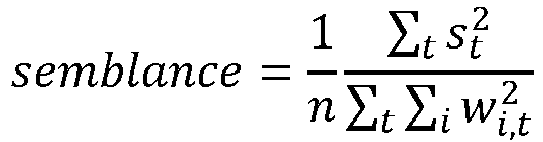
- According to the invention,
model component 312 is configured for a second stage of refining the constrained subsurface fiber optic data set by applying a second set of models to the limited subsurface fiber optic data set. The second set of models includes an interferometry model and a time reversal model. The interferometry model uses superimposed waves to extract information based on the relationship of the waves. The time reversal model takes advantage of the reciprocity of wave propagation to update an estimated location of a subsurface event and/or other information. - According to the invention, applying the interferometry model to the limited subsurface fiber optic data set includes binning the limited subsurface fiber optic data set, or otherwise separating and grouping the limited subsurface fiber optic data set. Cross-correlations are calculated for individual bins of the limited subsurface fiber optic data set. Cross-correlations are calculated between a reference subsurface fiber optic data in a selected bin and other subsurface fiber optic data set from the limited subsurface fiber optic data set. Cross-correlating the binned limited subsurface fiber optic data set includes migrating, or shifting, traces to the given subsurface volume of interest based on a shift, such as a phase shift, between the reference trace and the other traces from the limited subsurface fiber optic data set. Migrating traces may be based on traveltime differences. A trace may be a single subsurface fiber optic data. In some implementations, the traces may be migrated according to different interferometry models, such as a Kirchhoff-based interferometry model.
- According to the invention, the migrated traces form a partial digital seismic image based on the subsurface fiber optic data in a given bin. The correlation, or multiplication, of the partial digital seismic images may resolve vertical resolution issues often found in other interferometric methods. The partial digital seismic images are combined using a hybrid imaging system capable of properly combining partial digital seismic images. Previous systems have been unable to properly combine partial digital seismic images. The combined digital seismic image is used to generate an updated location.
- In some implementations, applying the time reversal model to the limited subsurface fiber optic data set may include muting traces that are not included in the limited subsurface fiber optic data set. Applying the time reversal model to the limited subsurface fiber optic data set may include normalizing the remaining traces and using the absolute value as input. Applying the time reversal method to the limited subsurface fiber optic data set may generate an updated location.
- According to the invention, refining the limited subsurface fiber optic data includes determining whether the updated location of the limited subsurface fiber optic data set using the interferometry model and the updated location of the limited subsurface fiber optic data set using the time reversal model are within a threshold spatial value. The threshold spatial value may be user defined or based on machine learning trained on other subsurface data. For example, the threshold spatial value may be approximately 70% of the maximum spatial value to remove some false-positive events. The refined subsurface fiber optic data set includes the limited subsurface fiber optic data set within the threshold spatial value. The threshold spatial value may be user defined or based on machine learning trained on other subsurface data.
- According to the invention, an origin time is estimated and/or updated. The origin time, arrival time, and propagation time may be related as arrival time can equal origin time plus propagation time. The origin time may then be determined as a function of arrival time and propagation time. The one or more sensors may record, or otherwise detect, arrival times of the subsurface events. Propagation time may be a function of the velocity model and event location. For example, the propagation time may be a distance between the event location and the one or more sensors divided by the velocity. Using the estimated location from the refined subsurface fiber optic data set, an origin time can be estimated.
- In some implementations,
model component 312 may be configured to obtain and/or generate velocity models. Simple velocity models may be appropriate for many use cases. For these cases, a homogeneous RMS velocity model may be used for fast-tracking purposes. In some implementations, well data, which may include well logs, may be used to generate a velocity model. The velocity model may be used to perform ray tracing between the corresponding sensor and one or more positions in the subsurface volume of interest that may correspond to a subsurface event. The ray tracing output may be used as input for a traveltime table to determine an amount of time that has elapsed between the subsurface event and the one or more sensors detecting the subsurface event. -
Moment tensor component 314 may be configured to generate a moment tensor corresponding to the given subsurface event using the refined subsurface fiber optic data set and the sensor data set. In implementations, the sensor data set may include generating an initial estimate of the moment tensor values based on the refined subsurface fiber optic data set and the sensor data set. In some implementations, the sensor data set may include updating the initial estimate of the moment tensor values based on the updated location. Moment tensors may be a representation of a fault movement, including the fault geometry and a slip vector. Moment tensors may include 9 components. Each component may correspond to one basic mode, a force couple seismic source. 6 components of the moment tensor may be independent, while the other 3 are dependent based on angular moment conservation. - In some implementations, the initial estimate of the moment tensor may be based on the refined subsurface fiber optic data set, sensor data set, a wavespeed structure, root mean square (RMS) velocity, an analytical Green Tensor, and/or other information. For example, less complex systems, such as analytical Green Tensor in homogeneous isotropic medium may be used for a quick turn-around estimation.
- In some implementations, using the initial estimate of the moment tensor and the wavespeed structure, a non-linear problem may be solved to update an event location of the moment tensor.
- In some implementations, using the updated event location, a linear problem may be solved to update the moment tensor based on the Green Tensor calculated in a complex wavespeed structure using modeling. The modeling may include finite difference modeling and/or other models. The sensor data set may include additional information relating to polarity, direction, data from other sources in the subsurface volume of interest, and/or other information.
- In implementations, the sensor data set may include repeating the steps of updating an event location and updating the moment tensor until the difference between subsequent moment tensor values drops below a threshold moment tensor value. The threshold moment tensor value may be user defined or based on machine learning trained on other subsurface data. For example, the threshold moment tensor value may be approximately 5% of the absolute moment tensor value. In other words, if the relative change of the moment tensor is less than 5%, iterations can be safely terminated.
- Digital
seismic image component 316 may be configured to generate a digital seismic image that represents the moment tensor and the refined subsurface fiber optic data set using visual effects to depict at least a portion of the moment tensor and at least a portion of the parameter values in the refined subsurface fiber optic data set as a function of position within the subsurface volume of interest. - Digital
seismic image component 316 may be configured to generate a digital seismic image that represents the subsurface fiber optic data set, the limited subsurface fiber optic data set, the refined subsurface fiber optic data set, and/or any other portion of the subsurface fiber optic data set, as well as the sensor data set. - In some implementations, digital
seismic image component 316 may be configured to display the digital seismic image on a graphical user interface. In some implementations, the graphical user interface may be configured to perform further analysis on the final detection and location results. For example, certain event detections, or data within the subsurface fiber optic data set, limited subsurface fiber optic data set, refined subsurface fiber optic data set, or subsurface data set may be manually removed using the graphical user interface, as will be described herein. - In some implementations, server(s) 302, client computing platform(s) 304, and/or
external resources 330 may be operatively linked via one or more electronic communication links. For example, such electronic communication links may be established, at least in part, via a network such as the Internet and/or other networks. It will be appreciated that this is not intended to be limiting, and that the scope of this disclosure includes implementations in which server(s) 302, client computing platform(s) 304, and/orexternal resources 330 may be operatively linked via some other communication media. - A given
client computing platform 304 may include one or more processors configured to execute computer program components. The computer program components may be configured to enable an expert or user associated with the givenclient computing platform 304 to interface withsystem 300 and/orexternal resources 330, and/or provide other functionality attributed herein to client computing platform(s) 304. By way of non-limiting example, the givenclient computing platform 304 may include one or more of a desktop computer, a laptop computer, a handheld computer, a tablet computing platform, a NetBook, a Smartphone, a gaming console, and/or other computing platforms. -
External resources 330 may include sources of information outside ofsystem 300, external entities participating withsystem 300, and/or other resources. In some implementations, some or all of the functionality attributed herein toexternal resources 330 may be provided by resources included insystem 300. - Server(s) 302 may include
electronic storage 332, one ormore processors 334, and/or other components. Server(s) 302 may include communication lines, or ports to enable the exchange of information with a network and/or other computing platforms. Illustration of server(s) 302 inFIG. 3 is not intended to be limiting. Server(s) 302 may include a plurality of hardware, software, and/or firmware components operating together to provide the functionality attributed herein to server(s) 302. For example, server(s) 302 may be implemented by a cloud of computing platforms operating together as server(s) 302. -
Electronic storage 332 may include non-transitory storage media that electronically stores information. The electronic storage media ofelectronic storage 332 may include one or both of system storage that is provided integrally (i.e., substantially non-removable) with server(s) 302 and/or removable storage that is removably connectable to server(s) 302 via, for example, a port (e.g., a USB port, a firewire port, etc.) or a drive (e.g., a disk drive, etc.).Electronic storage 332 may include one or more of optically readable storage media (e.g., optical disks, etc.), magnetically readable storage media (e.g., magnetic tape, magnetic hard drive, floppy drive, etc.), electrical charge-based storage media (e.g., EEPROM, RAM, etc.), solid-state storage media (e.g., flash drive, etc.), and/or other electronically readable storage media.Electronic storage 332 may include one or more virtual storage resources (e.g., cloud storage, a virtual private network, and/or other virtual storage resources).Electronic storage 332 may store software algorithms, information determined by processor(s) 334, information received from server(s) 302, information received from client computing platform(s) 304, and/or other information that enables server(s) 302 to function as described herein. - Processor(s) 334 may be configured to provide information processing capabilities in server(s) 302. As such, processor(s) 334 may include one or more of a digital processor, an analog processor, a digital circuit designed to process information, an analog circuit designed to process information, a state machine, and/or other mechanisms for electronically processing information. Although processor(s) 334 is shown in
FIG. 3 as a single entity, this is for illustrative purposes only. In some implementations, processor(s) 334 may include a plurality of processing units. These processing units may be physically located within the same device, or processor(s) 334 may represent processing functionality of a plurality of devices operating in coordination. Processor(s) 334 may be configured to executecomponents components - It should be appreciated that although
components FIG. 3 as being implemented within a single processing unit, in implementations in which processor(s) 334 includes multiple processing units, one or more ofcomponents different components components components components components -
FIG. 4 illustrates amethod 400 for detecting a given subsurface event in a subsurface volume of interest, in accordance with one or more implementations. The operations ofmethod 400 presented below are intended to be illustrative. In some implementations,method 400 may be accomplished with one or more additional operations not described, and/or without one or more of the operations discussed. Additionally, the order in which the operations ofmethod 400 are illustrated inFIG. 4 and described below is not intended to be limiting. - In some implementations,
method 400 may be implemented in one or more processing devices (e.g., a digital processor, an analog processor, a digital circuit designed to process information, an analog circuit designed to process information, a state machine, and/or other mechanisms for electronically processing information). The one or more processing devices may include one or more devices executing some or all of the operations ofmethod 400 in response to instructions stored electronically on an electronic storage medium. The one or more processing devices may include one or more devices configured through hardware, firmware, and/or software to be specifically designed for execution of one or more of the operations ofmethod 400. - An
operation 402 includes receiving a subsurface fiber optic data set. The subsurface fiber optic data set corresponds to the given subsurface event using a fiber optic apparatus. A given subsurface fiber optic data specifies parameter values of parameters as a function of position of the fiber optic apparatus located in the subsurface volume of interest.Operation 402 is performed by one or more physical computer processors configured by machine-readable instructions including a component that is the same as or similar to fiberoptic data component 308, in accordance with one or more implementations. - An
operation 404 includes receiving a sensor data set. A given subsurface sensor data specifies parameter values of parameters as a function of position within the subsurface volume of interest.Operation 404 is performed by one or more physical computer processors configured by machine-readable instructions including a component that is the same as or similar tosensor data component 310, in accordance with one or more implementations. - An
operation 406 includes constraining the subsurface fiber optic data set to generate a constrained subsurface fiber optic data set. The subsurface fiber optic data set is constrained based on a given parameter value of a given parameter within a certain range.Operation 406 is performed by one or more physical computer processors configured by machine-readable instructions including a component that is the same as or similar to fiberoptic data component 308, in accordance with one or more implementations. - An
operation 408 includes using sets of models to refine the constrained subsurface fiber optic data set. The sets of models represent stages of refining the constrained subsurface fiber optic data set. A first set of models limits the constrained subsurface fiber optic data set and the second set of models refines the limited subsurface fiber optic data set. The refined constrained subsurface fiber optic data set is a refined subsurface fiber optic data set. In some implementations, operations 402-408 may be repeated to further refine event locations and origin times and to remove other false events. In implementations, shorter time windows and finer thresholding may be applied to improve accuracy.Operation 408 is performed by one or more physical computer processors configured by machine-readable instructions including a component that is the same as or similar tomodel component 312, in accordance with one or more implementations. - An
operation 410 may include generating a moment tensor. The moment tensor may be derived from the refined subsurface fiber optic data set and the sensor data set.Operation 410 may be performed by one or more physical computer processors configured by machine-readable instructions including a component that is the same as or similar tomoment tensor component 314, in accordance with one or more implementations. - An
operation 412 may include generating a digital seismic image. The digital seismic image may represent the moment tensor and the refined subsurface fiber optic data set using visual effects to depict at least a portion of the moment tensor and at least a portion of the parameter values in the refined subsurface fiber optic data set as a function of position within the subsurface volume of interest.Operation 412 may be performed by one or more physical computer processors configured by machine-readable instructions including a component that is the same as or similar to digitalseismic image component 316, in accordance with one or more implementations. - An
operation 414 may include displaying the digital seismic image on a graphical user interface.Operation 414 may be performed by one or more physical computer processors configured by machine-readable instructions including a component that is the same as or similar to digitalseismic image component 316, in accordance with one or more implementations. -
FIG. 5 illustrates DC effects filtered out, in accordance with one or more implementations. As illustrated, DC noise may be estimated based on a duplication of the stack of the band-limited input. The estimated DC noise may be removed from the band-limited input using direct subtraction. 500 may illustrate the raw data. 502 may illustrate the estimated DC. 504 may illustrate the raw data with the DC effects filtered out. -
FIG. 6 illustrates raw data and an example of processed data denoised by a machine-learning filter, in accordance with one or more implementations. 600 may illustrate raw data. 602 may illustrate denoised data. For example, the processed data may be denoised by a Wiener filter using machine learning. 604 may illustrate the noise that was removed in a denoising process. -
FIG. 7 illustrates an example probability map, in accordance with one or more implementations. As illustrated, theprobability map 700 may depict the spatial distribution of semblance values for a given origin time. Theprobability map 700 may not be normalized. -
FIG. 8 illustrates original data and steered and flattened data of location and origin times of subsurface events, in accordance with one or more implementations. As illustrated, theoriginal data 800 may be steered and flattened to help isolate the location and origin times of subsurface events. Flatter data may indicate better location and origin time. As illustrated, the data is not completely flattened in the steereddata 802 because the location and origin times are roughly estimated. A muting window, illustrated by the dotted lines, may help isolate a given subsurface event. This may help detect and remove false subsurface events, as well as avoid cross-talk between nearby events. For semblance analysis, a flatter curve may lead to a larger semblance value, while a less flat curve may correspond to a smaller semblance value. -
FIG. 9 illustrates a refined event location using a time reversal model, in accordance with the invention. As illustrated, using a time reversal model,map 900 illustrates a refined event location. -
FIG. 10 illustrates high resolution interferometry imaging, in accordance with the invention. As illustrated, highresolution interferometry imaging 1000 is a process of the presently disclosed technology. -
FIG. 11 illustratesoriginal data 1100 and steered and flatteneddata 1102 of refined location and origin time of a subsurface event, in accordance with one or more implementations. As illustrated, the flatteneddata 1102 based on the refined location and origin time is much flatter than the data inFIG. 7 , which indicates that the location and origin time are more accurate after refinement. -
FIG. 12 illustrates a false-positive event candidate that may be caused by crosstalk between two true events close to each other, which can be removed based on a marching-pursue approach. As illustrated, when two subsurface events that lead to large semblance values are close to each other, both may be detected as subsurface events, in addition to a false-positive event candidate that results from crosstalk between the two true events. In order to remove the false-positive event candidate, a semblance value is generated for the real subsurface events. Even though the semblance value of the false-positive subsurface event candidate may be larger than a defined threshold, it is still less than semblance values of the real subsurface events. And hence a marching-pursue approach may be used to rule out the false-positive event candidate. -
FIG. 13 illustrates raw data converted into steered data, which is then converted into stacked data, in accordance with one or more implementations. As illustrated, theraw data 1300 may be steered based on a predicted traveltime curve. The steereddata 1302 may flatten at the event origin time. Steering may include applying a normal moveout (NMO) correction and/or shifting the data as appropriate. NMO may describe the effect that the distance between a source and a sensor (the offset) has on the arrival time of a reflection in the form of an increase of time with offset, and NMO correction may correct such an effect. For example, NMO correction may account for hyperbolic characteristics of subsurface data, or other characteristics, due to the one or more sensors being located in positions away from the source of the subsurface event. - Shifting may include moving data based on a corresponding propagation time. For example, a sensor closer to the subsurface event may have a shorter propagation time while a sensor further away from the subsurface event may have a longer propagation time. Shifting may align the data as illustrated in the steered data window. As illustrated, a stack of the
traces 1304 helps depict the event origin time based on the highest amplitude. Stacking may include adding the shifted traces together, such that the traces may add constructively to generate the signal in the stack window. In some implementations, time integration may be applied because the subsurface fiber optic data set may measure strain rate of particle movement, which is a time derivative of the strain. For a given trace, denoted as wt (the amplitude of the trace at time t), the time-integrated trace, denoted as yi (the amplitude of the trace at time i), may be defined and calculated as:
-
FIG. 14 illustrates an examplegraphical user interface 1400 to visualize and analyze results, in accordance with one or more implementations. The examplegraphical user interface 1400 may include multiple tools to visualize and analyze the data and to add, remove or refine the events detected by the presently disclosed technology workflow. Thegraphical user interface 1400 may help a user focus on a particular attribute or parameter corresponding to the fiber optic data and the sensor data. As illustrated, the tools may estimate parameters, perform semblance analysis, perform velocity analysis, perform origin time analysis, perform location analysis, pick waves, select parameters to adjust, change data, look at, and adjust, the workflow, apply NMO, and/or other operations. -
FIG. 15 illustrates synthetic data from multiple events, in accordance with one or more implementations. Thedata 1500 comes from 12 events with varying amplitudes, locations, and origin times. As illustrated, both P waves and S waves are present in the data and are used as the input to generateFIGS. 16 &17 . -
FIG. 16 illustrates the accuracy of estimated locations using a fiber optic apparatus, in accordance with one or more implementations. As illustrated, a three-dimensional representation 1600 of the fiber optic apparatus and the estimated and actual locations is depicted. Location errors may be within 30 ft and origin time errors may be within 2 ms. -
FIG. 17 illustrates the accuracy of estimated locations using a fiber optic apparatus, in accordance with one or more implementations. As illustrated, a zoomed-in two-dimensional representation 1700 of the estimated and actual event locations is depicted. Detections may be removed that do not correspond to true events based on the visual representation. Otherwise,FIG. 17 may be substantially similar toFIG. 16 . -
FIG. 18 illustrates a relationship among moment tensor, fracture/fault plane, and subsurface fiber optic data. Once a moment tensor is determined, a fracture/fault plane can be derived, together with corresponding relative movement between the hanging-wall and foot-wall of the fracture/fault, which could be dip-slip, strike-slip, and/or opening/closing. A dominantly strike-slip fault is depicted, with a corresponding moment tensor. In accordance with one or more implementations, the moment tensor can be accurately inverted by matching waveforms between observed data and modeled data. Comparisons between input and modeled data and between true moment tensor and inverted moment tensor are depicted as well. -
FIG. 19 illustrates anexample graph 1900 of semblance values as a function of RMS velocities and normal traveltime, for a subsurface event, in accordance with one or more implementations. Each pair of RMS velocity and normal traveltime, i.e., a colored point on the graph (white/red means small/large semblance values respectively, as indicated on the temperature bar), leads to a different traveltime curve in the subsurface fiber optic data set. The semblance value of the corresponding point may be calculated as defined above, after traveltime-based NMO correction or otherwise shifting correction. As illustrated, the high-semblance area 1902 represents possible RMS velocity and normal traveltime pairs that fit one subsurface event in the subsurface fiber optic data set. Thepoint 1904 corresponds to an RMS velocity of about 2438.4 m/s (8000 ft/s) and normal travel time of about 97 ms, leading to about a 0.1 semblance value. The approximate value of 2438.4 m/s (8000 ft/s) may be preselected based on the typical speed of SH waves in the local geological setting. However, thepoint 1906, with RMS velocity of about 2819.4 m/s (9250 ft/s) and normal travel time of about 77 ms, leads to a larger semblance value of about 0.15, which indicates RMS velocity of about 2819.4 m/s (9250 ft/s) fits the subsurface event in the subsurface fiber optic data set better than the about 2438.4 m/s (8000 ft/s) RMS velocity selected. As illustrated, a grid search of RMS velocity and normal traveltime pairs for each subsurface event candidate may provide ideal RMS velocities for subsurface events that account for different ray/propagation paths, which leads to more accurate event locations. -
FIG. 20A illustrates anexample interface 2000 displaying multiple event locations, in accordance with one or more implementations. As illustrated, themap 2000 may be a top-down view of a subsurface volume of interest. ADAS cable 2002 is illustrated in the bottom-left corner corresponding to its location in the subsurface volume of interest. The dots may represent locations of event candidates. Sizes of the dots may represent magnitudes of the event candidate (e.g., larger dots may have a greater magnitude while smaller dots have a smaller magnitude). Colors of the dots may represent corresponding semblance values (e.g., blue may correspond to lower semblance values, or less likely to be a subsurface event, while red dots have higher semblance values, or are more likely to be a subsurface event). Theinterface 2000 may allow a user to manually quality check the event candidates (i.e., remove likely false positives). Theexample interface 2000 may allow a user to select offset range changes, perform semblance calculations in a data domain, and display source event image area size. For example, a threshold semblance value of about 0.2 may be used to remove any event that has a smaller semblance value. The event image area size may be limited to less than about 30 ft along each direction, to remove any event that has a larger uncertainty. Those threshold values may depend on signal-to-noise ratios, the data quality, event distances from the fiber optic cable, event magnitudes and mechanisms, and thus may vary drastically for different scenarios and applications. A user may select a small portion of the events, look at their corresponding fits in the subsurface fiber optic data set, evaluate quality of the fits, and determine appropriate threshold values based on observations during this event filtering and selection process. -
FIG. 20B illustrates an example interface 2010 displaying multiple event locations, after event filtering and selection, in accordance with one or more implementations. Themap 2000 ofFIG. 20B may be similar to the map 2010 inFIG. 20A described above. The map 2010 ofFIG. 20B may be edited based on one or more factors. For example, editing or other quality control may be based on colors of the dots and/or size of the dots. In one example, all blue dots may be removed. In one example, dots that are smaller than a certain size threshold, or magnitude threshold, may be removed. In implementations, a combination of these factors may be used to edit the event candidates. For example, blue dots outside a radius of the center of concentrated red dots may be removed. -
FIG. 21 illustrates example event candidates using a fiber optic apparatus and one or more geophones, in accordance with one or more implementations. As illustrated, afiber optic apparatus 2101 may detect a subsurface event. A horizontally orientedfiber optic apparatus 2101 may be able to detect a subsurface event surrounding the center of a sensor on a 2D plane. Based on a homogeneous velocity model, or other simple velocity model, there may be a cylindrical symmetry around the sensor that detected the subsurface event. Theentire circle 2110 may represent the event candidates based on the subsurface fiber optic data detected. - Leveraging the cylindrical symmetry of the subsurface fiber optic data, a refined location of the subsurface event may be determined using geophones 2102 (e.g., 1C surface geophone, 3C downhole geophones, etc.) and/or other sensors (e.g., additional fiber optic apparatuses oriented perpendicularly or in parallel). It should be appreciated that for more complex velocity models, there may not be a cylindrical symmetry and other shapes or curves may correspond to the complex velocity models. Semblance analysis may be applied to the
circle 2110, or other appropriate shape, to determine the true event location. Thelocation 2108 that corresponds to the highest semblance value will be the correct event location on the shape.Other locations circle 2110 where geophone data or other sensor data was detected. It should be appreciated that if additional fiber optic apparatuses are deployed, additional circles may represent locations of potential subsurface events formed from the additional fiber optic apparatuses. These circles may intersect at a single point or at most two points for two fiber optic apparatuses. If there are two points of intersection, one of the two points may be easily removed as a false positive based on known drilling operations or other known events in the subsurface volume of interest. -
FIG. 22 illustrates amethod 2200 for detecting a given subsurface event in a subsurface volume of interest, in accordance with the invention. The operations ofmethod 2200 presented below are intended to be illustrative. In some implementations,method 2200 may be accomplished with one or more additional operations not described. Additionally, the order in which the operations ofmethod 2200 are illustrated inFIG. 22 and described below is not intended to be limiting. - According to the invention,
method 2200 is implemented in one or more processing devices (e.g., a physical computer processor, a digital processor, an analog processor, a digital circuit designed to process information, an analog circuit designed to process information, a state machine, and/or other mechanisms for electronically processing information). The one or more processing devices include one or more devices executing some or all of the operations ofmethod 2200 in response to instructions stored electronically on an electronic storage medium. The one or more processing devices may include one or more devices configured through hardware, firmware, and/or software to be specifically designed for execution of one or more of the operations ofmethod 2200. - An
operation 2202 includes receiving a subsurface fiber optic data set. The subsurface fiber optic data set corresponds to the given subsurface event using a fiber optic apparatus. A given subsurface fiber optic data specifies parameter values of parameters as a function of position of the fiber optic apparatus located in the subsurface volume of interest.Operation 2202 is performed by one or more physical computer processors configured by machine-readable instructions including a component that is the same as or similar to fiberoptic data component 308, in accordance with one or more implementations. - An
operation 2204 includes constraining the subsurface fiber optic data set to generate a constrained subsurface fiber optic data set. The subsurface fiber optic data set is constrained based on a given parameter value of a given parameter within a certain range.Operation 2204 is performed by one or more physical computer processors configured by machine-readable instructions including a component that is the same as or similar to fiberoptic data component 308, in accordance with one or more implementations. - An
operation 2206 includes using sets of models to refine the constrained subsurface fiber optic data set. The sets of models represent stages of refining the constrained subsurface fiber optic data set. A first set of models limits the constrained subsurface fiber optic data set and the second set of models refines the limited subsurface fiber optic data set. The refined constrained subsurface fiber optic data set is a refined subsurface fiber optic data set. In some implementations, operations 2202-2206 may be repeated to further refine event locations and origin times and to remove other false events. In implementations, shorter time windows and finer thresholding may be applied to improve accuracy.Operation 2206 is performed by one or more physical computer processors configured by machine-readable instructions including a component that is the same as or similar tomodel component 312, in accordance with one or more implementations. - An
operation 2208 includes estimating an event location. The estimated event location is generated based on using the sets of models. According to the invention, applying the interferometry model to the limited subsurface fiber optic data set generates a digital seismic image of locations of potential subsurface events, as described above. According to the invention, a time reversal model is used to generate an updated location. According to the invention, these models are compared using semblance analysis to initially refine potential location for the subsurface events.Operation 2208 is performed by one or more physical computer processors configured by machine-readable instructions including a component that is the same as or similar tosensor data component 310, in accordance with one or more implementations. - An
operation 2210 includes estimating an origin time. The origin time may be based on an arrival time and a propagation time. The propagation time may be based on a velocity model and an event location.Operation 2210 is performed by one or more physical computer processors configured by machine-readable instructions including a component that is the same as or similar to fiberoptic data component 308 and/orsensor data component 310, in accordance with one or more implementations. - An
operation 2212 may include receiving a sensor data set. A given subsurface sensor data may specify parameter values of parameters as a function of position within the subsurface volume of interest.Operation 2212 may be performed by one or more physical computer processors configured by machine-readable instructions including a component that is the same as or similar tosensor data component 310, in accordance with one or more implementations. - An
operation 2214 may include refining an event location. The refined event location may be based on the refined subsurface fiber optic data set and the sensor data set. As described above, the subsurface fiber optic data set may indicate that the refined event location is some distance away from a corresponding sensor. In implementations, these various distances may be equidistant from the corresponding sensor. The sensor data set may help specify from which direction the refined event location is located on the various distances away from the sensor. Semblance analysis may be applied to a stacked sensor data set to find a location that corresponds to the highest semblance value.Operation 2214 may be performed by one or more physical computer processors configured by machine-readable instructions including a component that is the same as or similar tosensor data component 310, in accordance with one or more implementations. - An
operation 2216 may include generating a digital seismic image. The digital seismic image may represent the refined subsurface fiber optic data set using visual effects to depict at least a portion of the parameter values in the refined subsurface fiber optic data set and a portion of the parameter values in the sensor data set as a function of position within the subsurface volume of interest.Operation 2216 may be performed by one or more physical computer processors configured by machine-readable instructions including a component that is the same as or similar to digitalseismic image component 316, in accordance with one or more implementations. - An
operation 2218 may include displaying the digital seismic image on a graphical user interface.Operation 2218 may be performed by one or more physical computer processors configured by machine-readable instructions including a component that is the same as or similar to digitalseismic image component 316, in accordance with one or more implementations. - It should be noted and understood that there can be improvements and modifications made of the present invention described above which don't depart from the scope of the invention as set forth in the accompanying claims.
Claims (14)
- A method for detecting a given subsurface event in a subsurface volume of interest, the method comprising:receiving (2202) a subsurface fiber optic data set of the given subsurface event, wherein the subsurface fiber optic data set comprises responses detected by a fiber optic apparatus, and wherein a given subsurface fiber optic data set specifies parameter values of parameters as a function of position in the subsurface volume of interest;constraining (2204) the subsurface fiber optic data set based on a given parameter value of a given parameter within a certain range to generate a constrained subsurface fiber optic data set;using (2206) sets of models to refine the constrained subsurface fiber optic data set to generate a refined subsurface fiber optic data set;estimating (2208) an event location of the given subsurface event based on the refined subsurface fiber optic data set; andestimating (2210) an origin time based on the event location, the method characterised in thatthe step of using the sets of models to generate the refined subsurface fiber optic data set comprises:limiting the constrained subsurface fiber optic data set into a limited subsurface fiber optic data set;applying an interferometry model to the limited subsurface fiber optic data set, wherein applying the interferometry model to the limited subsurface fiber optic data set comprises:binning the limited subsurface fiber optic data set;calculating cross-correlations between a reference subsurface fiber optic data in a selected bin and other subsurface fiber optic data set from the limited subsurface fiber optic data set;migrating traces to the given subsurface volume of interest based on a shift between the reference trace and the traces from the limited subsurface fiber optic data set to generate partial digital seismic images; andcombining the partial digital seismic images to generate an updated event location;applying a time reversal model to the limited subsurface fiber optic data set to estimate the event location; andrefining the limited subsurface fiber optic data set based on whether the event location using the interferometry model and the event location using the time reversal model are within a threshold spatial value to generate a refined subsurface fiber optic data set.
- The method of claim 1, further comprising:receiving (2212) a sensor data set of the given subsurface event, wherein the sensor data set comprises responses detected by a sensor, and wherein a given sensor data specifies parameter values of parameters as a function of position within the subsurface volume of interest; andrefining (2214) the event location of the subsurface event using the sensor data set.
- The method of claim 2, wherein refining the event location of the subsurface event using the sensor data set comprises:identifying a set of potential locations based on the refined subsurface fiber optic data set;deriving directionality from sensor data set based on polarization analysis, wherein the sensor data set comprises responses detected by a subsurface geophone; andselecting a correct location among the set of potential locations using the refined subsurface fiber optic data set and the sensor data set.
- The method of claim 2, wherein refining the event location of the subsurface event using the sensor data set comprises:identifying a set of potential locations based on the refined subsurface fiber optic data set;deriving multiple location semblance values based on travel times to one or more sensors corresponding to the sensor data set, wherein the sensor data set comprises responses detected by a surface geophone; andrefining the event location from the set of potential locations based on one of the multiple location semblance values.
- The method of claim 2, further comprising:generating (2216) a digital seismic image that represents the refined subsurface fiber optic data set using visual effects to depict at least a portion of the parameter values in the refined subsurface fiber optic data set and at least a portion of the parameter values in the sensor data set as a function of position within the subsurface volume of interest; anddisplaying (2218) the digital seismic image on a graphical user interface.
- The method of claim 1, wherein the fiber optic apparatus forms a distributed acoustic sensing cable.
- The method of claim 2, wherein:the sensor comprises one or more of a fiber optic apparatus or a geophone; orthe sensor data set is used to derive a wavespeed structure.
- The method of claim 1, wherein a first set of models comprises:a multiple signal classification model, anda semblance-based model,optionally wherein the method further comprises:generating sets of probability maps of a given subsurface event by applying the first set of models to the constrained subsurface fiber optic data sets, wherein a given set of probability maps comprises a first probability map based on applying the multiple signal classification model and a second probability map based on applying the semblance-based model;limiting the constrained subsurface fiber optic data set based on whether a semblance value of the given set of probability maps surpasses a threshold semblance value to generate the limited subsurface fiber optic data set.
- The method of claim 7 or 8, further comprising determining whether semblance values of the refined subsurface fiber optic data set surpasses a refined threshold value.
- The method of claim 1, wherein an origin time may be updated by applying one or more of the subsurface fiber optic data set, the constrained subsurface fiber optic data set, and the refined subsurface fiber optic data set.
- The method of claim 1, wherein estimating an origin time based on the event location comprises:obtaining a velocity model; andestimating an origin time based on arrival times corresponding to the refined subsurface fiber optic data set and propagation times based on the velocity model and the event location,optionally wherein:the velocity model is based on well data; orthe origin time is a given arrival time minus a corresponding propagation time.
- A system for detecting a given subsurface event in a subsurface volume of interest, the system comprising:electronic storage;one or more physical computer processors configured by machine readable instructions to carry out the method of any of the preceding claims.
- A computer program comprising instructions that, when executed by one or more physical computer processors, cause the one or more physical computer processors to refine estimated effects of parameters on amplitudes by performing the method of any of claims 1 to 11.
- A non-transitory computer readable medium having the computer program of claim 13 stored thereon.
Applications Claiming Priority (2)
| Application Number | Priority Date | Filing Date | Title |
|---|---|---|---|
| US201862698685P | 2018-07-16 | 2018-07-16 | |
| PCT/US2019/041837 WO2020018437A1 (en) | 2018-07-16 | 2019-07-15 | Systems and methods for detecting a subsurface event |
Publications (3)
| Publication Number | Publication Date |
|---|---|
| EP3824321A1 EP3824321A1 (en) | 2021-05-26 |
| EP3824321A4 EP3824321A4 (en) | 2022-04-06 |
| EP3824321B1 true EP3824321B1 (en) | 2023-06-28 |
Family
ID=69140183
Family Applications (1)
| Application Number | Title | Priority Date | Filing Date |
|---|---|---|---|
| EP19838238.4A Active EP3824321B1 (en) | 2018-07-16 | 2019-07-15 | Systems and methods for detecting a subsurface event |
Country Status (5)
| Country | Link |
|---|---|
| US (1) | US11187071B2 (en) |
| EP (1) | EP3824321B1 (en) |
| AR (1) | AR119654A1 (en) |
| AU (1) | AU2019306507B2 (en) |
| WO (1) | WO2020018437A1 (en) |
Families Citing this family (40)
| Publication number | Priority date | Publication date | Assignee | Title |
|---|---|---|---|---|
| EP3708769B1 (en) | 2016-04-07 | 2024-09-11 | BP Exploration Operating Company Limited | Detecting downhole sand ingress locations |
| BR112018070577A2 (en) | 2016-04-07 | 2019-02-12 | Bp Exploration Operating Company Limited | detection of downhole sand ingress locations |
| WO2018178279A1 (en) | 2017-03-31 | 2018-10-04 | Bp Exploration Operating Company Limited | Well and overburden monitoring using distributed acoustic sensors |
| US11199085B2 (en) | 2017-08-23 | 2021-12-14 | Bp Exploration Operating Company Limited | Detecting downhole sand ingress locations |
| WO2019060249A1 (en) * | 2017-09-21 | 2019-03-28 | The Regents Of The University Of California | Moment tensor reconstruction |
| EA202090867A1 (en) | 2017-10-11 | 2020-09-04 | Бп Эксплорейшн Оперейтинг Компани Лимитед | DETECTING EVENTS USING FEATURES IN THE AREA OF ACOUSTIC FREQUENCIES |
| US10928542B2 (en) * | 2018-06-07 | 2021-02-23 | Halliburton Energy Services, Inc. | Method of determining full green's tensor with resistivity measurement |
| US11634973B2 (en) * | 2018-10-04 | 2023-04-25 | Halliburton Energy Services, Inc. | Dynamic strain detection for cable orientation during perforation operations |
| US12571301B2 (en) | 2018-11-29 | 2026-03-10 | Bp Exploration Operating Company Limited | DAS data processing to identify fluid inflow locations and fluid type |
| NO20210262A1 (en) * | 2018-12-07 | 2021-02-26 | Halliburton Energy Services Inc | Simultaneous acquisition of distributed acoustic sensing for monitoring |
| GB201820331D0 (en) | 2018-12-13 | 2019-01-30 | Bp Exploration Operating Co Ltd | Distributed acoustic sensing autocalibration |
| US10962408B2 (en) * | 2019-03-07 | 2021-03-30 | Saudi Arabian Oil Company | Quasi-fundamental-mode operated multimode fiber for distributed acoustic sensing |
| US11675099B2 (en) * | 2019-05-23 | 2023-06-13 | Halliburton Energy Services, Inc. | De-spiking distributed acoustic sensor seismic profile |
| US11585212B2 (en) * | 2019-09-03 | 2023-02-21 | Halliburton Energy Services, Inc. | Anisotropy model guided fracture properties extraction from VSP data |
| US12196074B2 (en) | 2019-09-20 | 2025-01-14 | Lytt Limited | Systems and methods for sand ingress prediction for subterranean wellbores |
| WO2021073740A1 (en) | 2019-10-17 | 2021-04-22 | Lytt Limited | Inflow detection using dts features |
| EP4045766A1 (en) | 2019-10-17 | 2022-08-24 | Lytt Limited | Fluid inflow characterization using hybrid das/dts measurements |
| WO2021093974A1 (en) | 2019-11-15 | 2021-05-20 | Lytt Limited | Systems and methods for draw down improvements across wellbores |
| JP2023510777A (en) * | 2020-01-10 | 2023-03-15 | オーエフエス ファイテル,エルエルシー | Enhanced high-temperature hydrogen scattering resistance in optical fibers |
| GB2605319B (en) * | 2020-01-17 | 2024-01-31 | Landmark Graphics Corp | Continuous assessment of well elements using fiber optics |
| EP4491845A3 (en) * | 2020-06-11 | 2025-03-12 | Lytt Limited | Systems and methods for monitoring fluid outflow flow along a wellbore |
| WO2021254633A1 (en) | 2020-06-18 | 2021-12-23 | Lytt Limited | Event model training using in situ data |
| EP4168647A1 (en) | 2020-06-18 | 2023-04-26 | Lytt Limited | Event model training using in situ data |
| US12561841B2 (en) * | 2021-02-04 | 2026-02-24 | Nec Corporation | Multilinear domain-specific domain generalization |
| US20240126009A1 (en) * | 2021-02-12 | 2024-04-18 | Ofs Fitel, Llc | Systems and methods for enhanced back scattering in optical fibers with hermeticity |
| WO2022185539A1 (en) * | 2021-03-05 | 2022-09-09 | 日本電気株式会社 | Environment information acquisition device, environment information acquisition method, and computer readable medium |
| US11644351B2 (en) | 2021-03-19 | 2023-05-09 | Saudi Arabian Oil Company | Multiphase flow and salinity meter with dual opposite handed helical resonators |
| US11573346B2 (en) * | 2021-04-15 | 2023-02-07 | Saudi Arabian Oil Company | Determining a seismic quality factor for subsurface formations for marine vertical seismic profiles |
| CN114251085B (en) * | 2021-11-30 | 2023-01-20 | 中国石油天然气股份有限公司 | Method and device for evaluating sealing capability of simulated shaft collapse sediment |
| US12085687B2 (en) | 2022-01-10 | 2024-09-10 | Saudi Arabian Oil Company | Model-constrained multi-phase virtual flow metering and forecasting with machine learning |
| US12455392B2 (en) | 2022-08-05 | 2025-10-28 | Saudi Arabian Oil Company | Method to correct VSP data |
| US20240142422A1 (en) * | 2022-10-31 | 2024-05-02 | Halliburton Energy Services, Inc. | Marinized Distributed Acoustic Sensing System |
| EP4602401A4 (en) * | 2022-11-15 | 2026-02-18 | Services Petroliers Schlumberger | AUTOMATED SEISMIC EVENT DETECTION METHOD FOR THE DISTRIBUTED PROCESSING OF ACOUSTIC MEASUREMENT DATA IN A BOIL HOLE |
| US12242009B2 (en) | 2022-12-07 | 2025-03-04 | Saudi Arabian Oil Company | Method and system for measuring strain rate at a scale shorter than gauge length |
| CN116026250A (en) * | 2023-02-09 | 2023-04-28 | 重庆大学 | A Slip Monitoring Method for Block Faults |
| US20240309756A1 (en) * | 2023-03-15 | 2024-09-19 | Halliburton Energy Services, Inc. | Data recorder, a downhole data recording system, and a method of obtaining downhole data from a wellbore using the recording system and recorder |
| US20240318511A1 (en) * | 2023-03-15 | 2024-09-26 | Halliburton Energy Services, Inc. | Well system including a lower completion string coupled to a service string, the service string having one or more sensors positioned there along |
| US12503921B2 (en) | 2023-03-15 | 2025-12-23 | Halliburton Energy Services, Inc. | Multiple use wet mate having a fluid reservoir configured to receive a volume of coupling fluid therein |
| US12493137B1 (en) | 2024-06-11 | 2025-12-09 | Saudi Arabian Oil Company | Building natural fractures model using 3D stacked geological models |
| NO349557B1 (en) * | 2024-07-09 | 2026-02-23 | Reflection Marine Norge As | A DAS-Based Seismic Imaging Method |
Family Cites Families (10)
| Publication number | Priority date | Publication date | Assignee | Title |
|---|---|---|---|---|
| US6023443A (en) * | 1997-01-24 | 2000-02-08 | Baker Hughes Incorporated | Semblance processing for an acoustic measurement-while-drilling system for imaging of formation boundaries |
| US6424464B1 (en) * | 1999-05-06 | 2002-07-23 | Phillips Petroleum Company | Method and apparatus for interactive curved surface seismic interpretation and visualization |
| US6625541B1 (en) * | 2000-06-12 | 2003-09-23 | Schlumberger Technology Corporation | Methods for downhole waveform tracking and sonic labeling |
| US9075163B2 (en) * | 2009-04-17 | 2015-07-07 | Westerngeco L.L.C. | Interferometric seismic data processing |
| US20110286306A1 (en) * | 2010-05-21 | 2011-11-24 | Leo Eisner | Determining origin and mechanism of microseismic events in the earth's subsurface by deviatoric moment inversion |
| US9075155B2 (en) * | 2011-04-08 | 2015-07-07 | Halliburton Energy Services, Inc. | Optical fiber based downhole seismic sensor systems and methods |
| US10061046B2 (en) * | 2012-02-06 | 2018-08-28 | Ion Geophysical Corporation | Integrated passive and active seismic surveying using multiple arrays |
| US10302786B2 (en) | 2013-12-30 | 2019-05-28 | Cgg Services Sas | Methods and systems of determining a fault plane of a microseismic event |
| NO338113B1 (en) * | 2014-11-14 | 2016-08-01 | Octio As | System and method for monitoring microseismic events in a subsurface structure |
| US20180203144A1 (en) * | 2015-05-20 | 2018-07-19 | Optasense, Inc. | Interferometric Microseismic Imaging Methods and Apparatus |
-
2019
- 2019-07-15 AU AU2019306507A patent/AU2019306507B2/en active Active
- 2019-07-15 EP EP19838238.4A patent/EP3824321B1/en active Active
- 2019-07-15 US US16/511,795 patent/US11187071B2/en active Active
- 2019-07-15 WO PCT/US2019/041837 patent/WO2020018437A1/en not_active Ceased
- 2019-07-16 AR ARP190102010A patent/AR119654A1/en active IP Right Grant
Also Published As
| Publication number | Publication date |
|---|---|
| EP3824321A4 (en) | 2022-04-06 |
| US11187071B2 (en) | 2021-11-30 |
| AU2019306507B2 (en) | 2024-05-16 |
| WO2020018437A1 (en) | 2020-01-23 |
| AU2019306507A1 (en) | 2021-02-04 |
| EP3824321A1 (en) | 2021-05-26 |
| US20200018149A1 (en) | 2020-01-16 |
| AR119654A1 (en) | 2022-01-05 |
Similar Documents
| Publication | Publication Date | Title |
|---|---|---|
| US11187071B2 (en) | Systems and methods for detecting a subsurface event | |
| US12104484B2 (en) | Well log correlation and propagation system | |
| EP3769128B1 (en) | Determining anisotropy for a build section of a wellbore | |
| US11644589B2 (en) | Analogue facilitated seismic data interpretation system | |
| AU2019263741B2 (en) | Correcting a digital seismic image using a function of speed of sound in water derived from fiber optic sensing | |
| US11255994B2 (en) | Earth model generation via measurements | |
| US9075158B2 (en) | Using a drill bit as a seismic source for SET velocity analysis | |
| US10705056B2 (en) | Method for analyzing cement integrity in cased wells using sonic logging | |
| WO2019055565A1 (en) | Seismic image data interpretation system | |
| US20180031723A1 (en) | Method for an automatic detection of acoustic reflectors and their parameters from borehole acoustic array data | |
| CN109804135A (en) | Downhole optic fiber hydrophone | |
| US11719843B2 (en) | Determining a vertically transverse isotropy (VTI) anisotropy along a horizontal section of a wellbore drilled into a formation | |
| EP3791216B1 (en) | Geologic formation neutron porosity system | |
| NO344460B1 (en) | Methods and systems for identifying and plugging subterranean conduits | |
| Kumar et al. | Borehole seismic: Essential contributions over the oilfield lifecycle | |
| US20250277918A1 (en) | 3d angle-domain seismic residual statics | |
| WO2025175409A1 (en) | Method and system for rock physics-based grid refinement of grid in forward stratigraphic modeling | |
| US20260079273A1 (en) | Higher-order parallel fast sweeping method in anisotropic medium | |
| Kemper et al. | Real time velocity and pore pressure model calibration in exploration drilling |
Legal Events
| Date | Code | Title | Description |
|---|---|---|---|
| STAA | Information on the status of an ep patent application or granted ep patent |
Free format text: STATUS: THE INTERNATIONAL PUBLICATION HAS BEEN MADE |
|
| PUAI | Public reference made under article 153(3) epc to a published international application that has entered the european phase |
Free format text: ORIGINAL CODE: 0009012 |
|
| STAA | Information on the status of an ep patent application or granted ep patent |
Free format text: STATUS: REQUEST FOR EXAMINATION WAS MADE |
|
| 17P | Request for examination filed |
Effective date: 20210115 |
|
| AK | Designated contracting states |
Kind code of ref document: A1 Designated state(s): AL AT BE BG CH CY CZ DE DK EE ES FI FR GB GR HR HU IE IS IT LI LT LU LV MC MK MT NL NO PL PT RO RS SE SI SK SM TR |
|
| DAV | Request for validation of the european patent (deleted) | ||
| DAX | Request for extension of the european patent (deleted) | ||
| A4 | Supplementary search report drawn up and despatched |
Effective date: 20220303 |
|
| RIC1 | Information provided on ipc code assigned before grant |
Ipc: G01V 1/18 20060101ALI20220225BHEP Ipc: G01V 8/16 20060101ALI20220225BHEP Ipc: G01V 3/38 20060101ALI20220225BHEP Ipc: G01V 1/28 20060101ALI20220225BHEP Ipc: G01V 1/22 20060101ALI20220225BHEP Ipc: G01V 1/20 20060101AFI20220225BHEP |
|
| REG | Reference to a national code |
Ref country code: DE Ref legal event code: R079 Free format text: PREVIOUS MAIN CLASS: G01V0001200000 Ipc: G01V0001220000 Ref document number: 602019031859 Country of ref document: DE |
|
| RIC1 | Information provided on ipc code assigned before grant |
Ipc: G01V 1/18 20060101ALI20221209BHEP Ipc: G01H 9/00 20060101ALI20221209BHEP Ipc: E21B 47/135 20120101ALI20221209BHEP Ipc: G01V 8/16 20060101ALI20221209BHEP Ipc: G01V 3/38 20060101ALI20221209BHEP Ipc: G01V 1/28 20060101ALI20221209BHEP Ipc: G01V 1/20 20060101ALI20221209BHEP Ipc: G01V 1/22 20060101AFI20221209BHEP |
|
| GRAP | Despatch of communication of intention to grant a patent |
Free format text: ORIGINAL CODE: EPIDOSNIGR1 |
|
| STAA | Information on the status of an ep patent application or granted ep patent |
Free format text: STATUS: GRANT OF PATENT IS INTENDED |
|
| INTG | Intention to grant announced |
Effective date: 20230120 |
|
| RIN1 | Information on inventor provided before grant (corrected) |
Inventor name: WU, CHUNLING Inventor name: HU, CHAOSHUN Inventor name: ZHANG, LEONARD LIN Inventor name: LUO, YANG |
|
| GRAS | Grant fee paid |
Free format text: ORIGINAL CODE: EPIDOSNIGR3 |
|
| GRAA | (expected) grant |
Free format text: ORIGINAL CODE: 0009210 |
|
| STAA | Information on the status of an ep patent application or granted ep patent |
Free format text: STATUS: THE PATENT HAS BEEN GRANTED |
|
| AK | Designated contracting states |
Kind code of ref document: B1 Designated state(s): AL AT BE BG CH CY CZ DE DK EE ES FI FR GB GR HR HU IE IS IT LI LT LU LV MC MK MT NL NO PL PT RO RS SE SI SK SM TR |
|
| P01 | Opt-out of the competence of the unified patent court (upc) registered |
Effective date: 20230522 |
|
| REG | Reference to a national code |
Ref country code: CH Ref legal event code: EP |
|
| REG | Reference to a national code |
Ref country code: AT Ref legal event code: REF Ref document number: 1583195 Country of ref document: AT Kind code of ref document: T Effective date: 20230715 |
|
| REG | Reference to a national code |
Ref country code: IE Ref legal event code: FG4D |
|
| REG | Reference to a national code |
Ref country code: DE Ref legal event code: R096 Ref document number: 602019031859 Country of ref document: DE |
|
| REG | Reference to a national code |
Ref country code: NL Ref legal event code: FP |
|
| REG | Reference to a national code |
Ref country code: NO Ref legal event code: T2 Effective date: 20230628 |
|
| REG | Reference to a national code |
Ref country code: LT Ref legal event code: MG9D |
|
| PG25 | Lapsed in a contracting state [announced via postgrant information from national office to epo] |
Ref country code: SE Free format text: LAPSE BECAUSE OF FAILURE TO SUBMIT A TRANSLATION OF THE DESCRIPTION OR TO PAY THE FEE WITHIN THE PRESCRIBED TIME-LIMIT Effective date: 20230628 |
|
| REG | Reference to a national code |
Ref country code: AT Ref legal event code: MK05 Ref document number: 1583195 Country of ref document: AT Kind code of ref document: T Effective date: 20230628 |
|
| PG25 | Lapsed in a contracting state [announced via postgrant information from national office to epo] |
Ref country code: RS Free format text: LAPSE BECAUSE OF FAILURE TO SUBMIT A TRANSLATION OF THE DESCRIPTION OR TO PAY THE FEE WITHIN THE PRESCRIBED TIME-LIMIT Effective date: 20230628 Ref country code: LV Free format text: LAPSE BECAUSE OF FAILURE TO SUBMIT A TRANSLATION OF THE DESCRIPTION OR TO PAY THE FEE WITHIN THE PRESCRIBED TIME-LIMIT Effective date: 20230628 Ref country code: LT Free format text: LAPSE BECAUSE OF FAILURE TO SUBMIT A TRANSLATION OF THE DESCRIPTION OR TO PAY THE FEE WITHIN THE PRESCRIBED TIME-LIMIT Effective date: 20230628 Ref country code: HR Free format text: LAPSE BECAUSE OF FAILURE TO SUBMIT A TRANSLATION OF THE DESCRIPTION OR TO PAY THE FEE WITHIN THE PRESCRIBED TIME-LIMIT Effective date: 20230628 Ref country code: GR Free format text: LAPSE BECAUSE OF FAILURE TO SUBMIT A TRANSLATION OF THE DESCRIPTION OR TO PAY THE FEE WITHIN THE PRESCRIBED TIME-LIMIT Effective date: 20230929 |
|
| PG25 | Lapsed in a contracting state [announced via postgrant information from national office to epo] |
Ref country code: FI Free format text: LAPSE BECAUSE OF FAILURE TO SUBMIT A TRANSLATION OF THE DESCRIPTION OR TO PAY THE FEE WITHIN THE PRESCRIBED TIME-LIMIT Effective date: 20230628 |
|
| PG25 | Lapsed in a contracting state [announced via postgrant information from national office to epo] |
Ref country code: SK Free format text: LAPSE BECAUSE OF FAILURE TO SUBMIT A TRANSLATION OF THE DESCRIPTION OR TO PAY THE FEE WITHIN THE PRESCRIBED TIME-LIMIT Effective date: 20230628 |
|
| PG25 | Lapsed in a contracting state [announced via postgrant information from national office to epo] |
Ref country code: ES Free format text: LAPSE BECAUSE OF FAILURE TO SUBMIT A TRANSLATION OF THE DESCRIPTION OR TO PAY THE FEE WITHIN THE PRESCRIBED TIME-LIMIT Effective date: 20230628 |
|
| PG25 | Lapsed in a contracting state [announced via postgrant information from national office to epo] |
Ref country code: IS Free format text: LAPSE BECAUSE OF FAILURE TO SUBMIT A TRANSLATION OF THE DESCRIPTION OR TO PAY THE FEE WITHIN THE PRESCRIBED TIME-LIMIT Effective date: 20231028 |
|
| PG25 | Lapsed in a contracting state [announced via postgrant information from national office to epo] |
Ref country code: SM Free format text: LAPSE BECAUSE OF FAILURE TO SUBMIT A TRANSLATION OF THE DESCRIPTION OR TO PAY THE FEE WITHIN THE PRESCRIBED TIME-LIMIT Effective date: 20230628 Ref country code: SK Free format text: LAPSE BECAUSE OF FAILURE TO SUBMIT A TRANSLATION OF THE DESCRIPTION OR TO PAY THE FEE WITHIN THE PRESCRIBED TIME-LIMIT Effective date: 20230628 Ref country code: RO Free format text: LAPSE BECAUSE OF FAILURE TO SUBMIT A TRANSLATION OF THE DESCRIPTION OR TO PAY THE FEE WITHIN THE PRESCRIBED TIME-LIMIT Effective date: 20230628 Ref country code: PT Free format text: LAPSE BECAUSE OF FAILURE TO SUBMIT A TRANSLATION OF THE DESCRIPTION OR TO PAY THE FEE WITHIN THE PRESCRIBED TIME-LIMIT Effective date: 20231030 Ref country code: IS Free format text: LAPSE BECAUSE OF FAILURE TO SUBMIT A TRANSLATION OF THE DESCRIPTION OR TO PAY THE FEE WITHIN THE PRESCRIBED TIME-LIMIT Effective date: 20231028 Ref country code: ES Free format text: LAPSE BECAUSE OF FAILURE TO SUBMIT A TRANSLATION OF THE DESCRIPTION OR TO PAY THE FEE WITHIN THE PRESCRIBED TIME-LIMIT Effective date: 20230628 Ref country code: EE Free format text: LAPSE BECAUSE OF FAILURE TO SUBMIT A TRANSLATION OF THE DESCRIPTION OR TO PAY THE FEE WITHIN THE PRESCRIBED TIME-LIMIT Effective date: 20230628 Ref country code: CZ Free format text: LAPSE BECAUSE OF FAILURE TO SUBMIT A TRANSLATION OF THE DESCRIPTION OR TO PAY THE FEE WITHIN THE PRESCRIBED TIME-LIMIT Effective date: 20230628 Ref country code: AT Free format text: LAPSE BECAUSE OF FAILURE TO SUBMIT A TRANSLATION OF THE DESCRIPTION OR TO PAY THE FEE WITHIN THE PRESCRIBED TIME-LIMIT Effective date: 20230628 |
|
| REG | Reference to a national code |
Ref country code: DE Ref legal event code: R119 Ref document number: 602019031859 Country of ref document: DE |
|
| PG25 | Lapsed in a contracting state [announced via postgrant information from national office to epo] |
Ref country code: PL Free format text: LAPSE BECAUSE OF FAILURE TO SUBMIT A TRANSLATION OF THE DESCRIPTION OR TO PAY THE FEE WITHIN THE PRESCRIBED TIME-LIMIT Effective date: 20230628 |
|
| REG | Reference to a national code |
Ref country code: CH Ref legal event code: PL |
|
| PG25 | Lapsed in a contracting state [announced via postgrant information from national office to epo] |
Ref country code: MC Free format text: LAPSE BECAUSE OF FAILURE TO SUBMIT A TRANSLATION OF THE DESCRIPTION OR TO PAY THE FEE WITHIN THE PRESCRIBED TIME-LIMIT Effective date: 20230628 |
|
| REG | Reference to a national code |
Ref country code: BE Ref legal event code: MM Effective date: 20230731 |
|
| PG25 | Lapsed in a contracting state [announced via postgrant information from national office to epo] |
Ref country code: LU Free format text: LAPSE BECAUSE OF NON-PAYMENT OF DUE FEES Effective date: 20230715 |
|
| PG25 | Lapsed in a contracting state [announced via postgrant information from national office to epo] |
Ref country code: MC Free format text: LAPSE BECAUSE OF FAILURE TO SUBMIT A TRANSLATION OF THE DESCRIPTION OR TO PAY THE FEE WITHIN THE PRESCRIBED TIME-LIMIT Effective date: 20230628 Ref country code: LU Free format text: LAPSE BECAUSE OF NON-PAYMENT OF DUE FEES Effective date: 20230715 |
|
| REG | Reference to a national code |
Ref country code: IE Ref legal event code: MM4A |
|
| PG25 | Lapsed in a contracting state [announced via postgrant information from national office to epo] |
Ref country code: DK Free format text: LAPSE BECAUSE OF FAILURE TO SUBMIT A TRANSLATION OF THE DESCRIPTION OR TO PAY THE FEE WITHIN THE PRESCRIBED TIME-LIMIT Effective date: 20230628 Ref country code: DE Free format text: LAPSE BECAUSE OF NON-PAYMENT OF DUE FEES Effective date: 20240201 Ref country code: CH Free format text: LAPSE BECAUSE OF NON-PAYMENT OF DUE FEES Effective date: 20230731 |
|
| PLBE | No opposition filed within time limit |
Free format text: ORIGINAL CODE: 0009261 |
|
| STAA | Information on the status of an ep patent application or granted ep patent |
Free format text: STATUS: NO OPPOSITION FILED WITHIN TIME LIMIT |
|
| PG25 | Lapsed in a contracting state [announced via postgrant information from national office to epo] |
Ref country code: IT Free format text: LAPSE BECAUSE OF FAILURE TO SUBMIT A TRANSLATION OF THE DESCRIPTION OR TO PAY THE FEE WITHIN THE PRESCRIBED TIME-LIMIT Effective date: 20230628 Ref country code: BE Free format text: LAPSE BECAUSE OF NON-PAYMENT OF DUE FEES Effective date: 20230731 |
|
| 26N | No opposition filed |
Effective date: 20240402 |
|
| PG25 | Lapsed in a contracting state [announced via postgrant information from national office to epo] |
Ref country code: IE Free format text: LAPSE BECAUSE OF NON-PAYMENT OF DUE FEES Effective date: 20230715 |
|
| PG25 | Lapsed in a contracting state [announced via postgrant information from national office to epo] |
Ref country code: IE Free format text: LAPSE BECAUSE OF NON-PAYMENT OF DUE FEES Effective date: 20230715 Ref country code: SI Free format text: LAPSE BECAUSE OF FAILURE TO SUBMIT A TRANSLATION OF THE DESCRIPTION OR TO PAY THE FEE WITHIN THE PRESCRIBED TIME-LIMIT Effective date: 20230628 |
|
| PG25 | Lapsed in a contracting state [announced via postgrant information from national office to epo] |
Ref country code: BG Free format text: LAPSE BECAUSE OF FAILURE TO SUBMIT A TRANSLATION OF THE DESCRIPTION OR TO PAY THE FEE WITHIN THE PRESCRIBED TIME-LIMIT Effective date: 20230628 |
|
| PG25 | Lapsed in a contracting state [announced via postgrant information from national office to epo] |
Ref country code: BG Free format text: LAPSE BECAUSE OF FAILURE TO SUBMIT A TRANSLATION OF THE DESCRIPTION OR TO PAY THE FEE WITHIN THE PRESCRIBED TIME-LIMIT Effective date: 20230628 |
|
| PGFP | Annual fee paid to national office [announced via postgrant information from national office to epo] |
Ref country code: GB Payment date: 20250529 Year of fee payment: 7 |
|
| PGFP | Annual fee paid to national office [announced via postgrant information from national office to epo] |
Ref country code: NL Payment date: 20250613 Year of fee payment: 7 |
|
| PGFP | Annual fee paid to national office [announced via postgrant information from national office to epo] |
Ref country code: FR Payment date: 20250610 Year of fee payment: 7 |
|
| PG25 | Lapsed in a contracting state [announced via postgrant information from national office to epo] |
Ref country code: CY Free format text: LAPSE BECAUSE OF FAILURE TO SUBMIT A TRANSLATION OF THE DESCRIPTION OR TO PAY THE FEE WITHIN THE PRESCRIBED TIME-LIMIT; INVALID AB INITIO Effective date: 20190715 |
|
| PG25 | Lapsed in a contracting state [announced via postgrant information from national office to epo] |
Ref country code: HU Free format text: LAPSE BECAUSE OF FAILURE TO SUBMIT A TRANSLATION OF THE DESCRIPTION OR TO PAY THE FEE WITHIN THE PRESCRIBED TIME-LIMIT; INVALID AB INITIO Effective date: 20190715 |
|
| PGFP | Annual fee paid to national office [announced via postgrant information from national office to epo] |
Ref country code: NO Payment date: 20250709 Year of fee payment: 7 |
|
| PG25 | Lapsed in a contracting state [announced via postgrant information from national office to epo] |
Ref country code: TR Free format text: LAPSE BECAUSE OF FAILURE TO SUBMIT A TRANSLATION OF THE DESCRIPTION OR TO PAY THE FEE WITHIN THE PRESCRIBED TIME-LIMIT Effective date: 20230628 |