EP3824259B1 - Method and apparatus for focus correction of multi-image laser beam quality measurements - Google Patents
Method and apparatus for focus correction of multi-image laser beam quality measurements Download PDFInfo
- Publication number
- EP3824259B1 EP3824259B1 EP19838228.5A EP19838228A EP3824259B1 EP 3824259 B1 EP3824259 B1 EP 3824259B1 EP 19838228 A EP19838228 A EP 19838228A EP 3824259 B1 EP3824259 B1 EP 3824259B1
- Authority
- EP
- European Patent Office
- Prior art keywords
- image
- focus
- laser beam
- focal plane
- slices
- Prior art date
- Legal status (The legal status is an assumption and is not a legal conclusion. Google has not performed a legal analysis and makes no representation as to the accuracy of the status listed.)
- Active
Links
Images







Classifications
-
- G—PHYSICS
- G01—MEASURING; TESTING
- G01J—MEASUREMENT OF INTENSITY, VELOCITY, SPECTRAL CONTENT, POLARISATION, PHASE OR PULSE CHARACTERISTICS OF INFRARED, VISIBLE OR ULTRAVIOLET LIGHT; COLORIMETRY; RADIATION PYROMETRY
- G01J1/00—Photometry, e.g. photographic exposure meter
- G01J1/42—Photometry, e.g. photographic exposure meter using electric radiation detectors
- G01J1/4228—Photometry, e.g. photographic exposure meter using electric radiation detectors arrangements with two or more detectors, e.g. for sensitivity compensation
-
- G—PHYSICS
- G01—MEASURING; TESTING
- G01J—MEASUREMENT OF INTENSITY, VELOCITY, SPECTRAL CONTENT, POLARISATION, PHASE OR PULSE CHARACTERISTICS OF INFRARED, VISIBLE OR ULTRAVIOLET LIGHT; COLORIMETRY; RADIATION PYROMETRY
- G01J1/00—Photometry, e.g. photographic exposure meter
- G01J1/02—Details
- G01J1/0214—Constructional arrangements for removing stray light
-
- G—PHYSICS
- G01—MEASURING; TESTING
- G01J—MEASUREMENT OF INTENSITY, VELOCITY, SPECTRAL CONTENT, POLARISATION, PHASE OR PULSE CHARACTERISTICS OF INFRARED, VISIBLE OR ULTRAVIOLET LIGHT; COLORIMETRY; RADIATION PYROMETRY
- G01J1/00—Photometry, e.g. photographic exposure meter
- G01J1/02—Details
- G01J1/04—Optical or mechanical part supplementary adjustable parts
- G01J1/0407—Optical elements not provided otherwise, e.g. manifolds, windows, holograms, gratings
- G01J1/0414—Optical elements not provided otherwise, e.g. manifolds, windows, holograms, gratings using plane or convex mirrors, parallel phase plates, or plane beam-splitters
-
- G—PHYSICS
- G01—MEASURING; TESTING
- G01J—MEASUREMENT OF INTENSITY, VELOCITY, SPECTRAL CONTENT, POLARISATION, PHASE OR PULSE CHARACTERISTICS OF INFRARED, VISIBLE OR ULTRAVIOLET LIGHT; COLORIMETRY; RADIATION PYROMETRY
- G01J1/00—Photometry, e.g. photographic exposure meter
- G01J1/02—Details
- G01J1/04—Optical or mechanical part supplementary adjustable parts
- G01J1/0407—Optical elements not provided otherwise, e.g. manifolds, windows, holograms, gratings
- G01J1/0422—Optical elements not provided otherwise, e.g. manifolds, windows, holograms, gratings using light concentrators, collectors or condensers
-
- G—PHYSICS
- G01—MEASURING; TESTING
- G01J—MEASUREMENT OF INTENSITY, VELOCITY, SPECTRAL CONTENT, POLARISATION, PHASE OR PULSE CHARACTERISTICS OF INFRARED, VISIBLE OR ULTRAVIOLET LIGHT; COLORIMETRY; RADIATION PYROMETRY
- G01J1/00—Photometry, e.g. photographic exposure meter
- G01J1/42—Photometry, e.g. photographic exposure meter using electric radiation detectors
- G01J1/4257—Photometry, e.g. photographic exposure meter using electric radiation detectors applied to monitoring the characteristics of a beam, e.g. laser beam, headlamp beam
-
- H—ELECTRICITY
- H01—ELECTRIC ELEMENTS
- H01S—DEVICES USING THE PROCESS OF LIGHT AMPLIFICATION BY STIMULATED EMISSION OF RADIATION [LASER] TO AMPLIFY OR GENERATE LIGHT; DEVICES USING STIMULATED EMISSION OF ELECTROMAGNETIC RADIATION IN WAVE RANGES OTHER THAN OPTICAL
- H01S3/00—Lasers, i.e. devices using stimulated emission of electromagnetic radiation in the infrared, visible or ultraviolet wave range
- H01S3/0014—Monitoring arrangements not otherwise provided for
Definitions
- Laser beam profilers are used for this purpose.
- One technique used to measure the quality of a focused laser beam is to acquire multiple images of the Rayleigh scatter of the beam, then process those images digitally to compute parameters such as beam waist size, beam centroid, angular divergence and M 2 beam propagation ratio and the like.
- a laser beam profiler apparatus that measures Rayleigh scattering is described in US patent 8,988,673 issued March 24, 2015 and assigned to Ophir-Spiricon, LLC.
- the present application discloses a method of focus correction of at least one image of a laser beam measurement system in order to accurately compute a wide variety of beam parameters.
- Exemplary beam parameters include beam waist size and location, beam centroid, Rayleigh range, angular divergence, beam parameter product, and M 2 beam propagation ratio. While the description included herewith discusses methods of correcting for focus errors, those skilled in the art will appreciate that a variety of methods may be used to measure and correct for various characteristics of laser beam measurements. Additionally, the focus correction methods described herein may be used with a variety of light beams.
- the invention relates to a method defined in claim 1.
- optical systems that are out of focus have a distinct two-dimensional point spread function or transfer function.
- these functions can be approximated by a set of simpler one-dimensional line spread functions or modulation transfer functions.
- the two-dimensional point spread function is approximated by simpler one-dimensional line spread functions that may be applied to one slice of an image at a time.
- the modulation transfer function for out-of-focus images may be characterized a priori, either mathematically or empirically.
- This out-of-focus modulation transfer function is denoted G( ⁇ ,d) where ⁇ represents the spatial frequency and d represents the distance of the object from the focal plane.
- the laser beam quality measurement apparatus may comprise an imaging device and optical system that have a modulation transfer function denoted H( ⁇ ) that may also be characterized a priori by a variety of methods.
- images of the beams are deconstructed slice by slice.
- the distance of the beam from the focal plane for a given slice of the image needs to be determined.
- d can be used to find the composite line spread function by convolving g(x,d) with h(x).
- the resulting function may be used to deconvolve y(x), the given slice of camera image.
- y(x) will be discrete, yielding accurate results if y(x) is effectively band limited to spatial frequencies below the Nyquist frequency as described below.
- b(x), g(x,d) and h(x) are considered to be discrete as well.
- An alternate expression of the transfer function needed for deconvolution may be G( ⁇ ,d)H( ⁇ ), which is the Fourier transform of g(x,d)*h(x).
- Y( ⁇ ) B( ⁇ )G( ⁇ ,d)H( ⁇ ).
- the deconvolution can be implemented in two dimensions, which is an approach widely used with focal correction.
- the two-dimensional point spread function (or impulse responses) h(x,y) and g(x,y,d) may be computed once their one-dimensional modulation transfer functions are known, and they may be used for the two-dimensional deconvolution.
- the computing requirements for this approach are significant, and for the purpose of imaging laser beams that do not change rapidly slice to slice, a one-dimensional deconvolution may suffice.
- a number of alternative methods for processing image data may be employed to correct for beam focus errors.
- the method for focus correction of laser beam quality measurements involves 1) capturing images of the beam and from them determining the axis of the beam in three dimensions, 2) dividing each image into multiple slices, 3) finding the distance from the beam axis to the focal plane for each slice of each image, 4) deconvolving each slice using the transfer function corresponding to that distance, and 5) reassembling the deconvolved slices into an image that can be used to compute beam parameters.
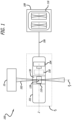
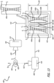
- Figure 1 shows a laser beam quality measurement apparatus 100.
- the apparatus may comprise at least one housing 101 with one or more imaging devices 104 positioned therein and in optical communication with at least one sampling region 130.
- One or more optical systems 150 may be in optical communication with the sampling region 130 and the imaging device 104.
- the laser beam quality measurement apparatus 100 need not include an optical system 150.
- any number of additional imaging or measurement devices and/or sensors may be used with the laser beam quality measurement apparatus 100.
- at least one laser or light source 10 may direct at least one beam 102 into and/or through the sampling region 130.
- the light source 10 may comprise light emitting diodes, superluminescent diodes, flashlight beams and the like.
- the imaging device 104 and optical system 150 may be configured to capture one or more light signals from the laser beam 102 and direct them via at least one conduit 106 to at least one image processing module 108.
- the imaging device 104 and optical system 150 may be configured to capture one or more light signals that are Rayleigh scattered from the beam 102, although those skilled in the art will appreciate that Raman scattering or any variety of scattering effects or other optical phenomena may be observed by the laser beam quality measurement system.
- the image processing module 108 may be configured to process at least one scattered light signal and display one or more images on one or more displays 116.
- the beam 102 may have one or more focal points or beam waists 128 as it propagates through the sampling region 130.
- the beam waist or focal point 128 may be defined as the location or region where the beam is most tightly focused or where the cross section of the beam is the smallest or where the beam power or optical fluence is most highly concentrated.
- the user may locate the beam waist on the surface of or within the material to be processed, though those skilled in the art will appreciate that that the beam waist may be positioned at a variety of positions relative to the material to be processed.
- the housing 101, the optical system 150 and the imaging device 104 may define one or more focal planes.
- the housing 101, the optical system 150 and the imaging devices 104 define two focal planes, P y and P x , and at least one plane Z, although those skilled in the art will appreciate that any number of housings or imaging devices may be used that define any number of planes or focal planes.
- plane Z is substantially orthogonal to the image planes P Y and P x , though in another embodiment plane Z may not be orthogonal to the image planes P y and P x .
- the operator may use at least one alignment device 110 to align the beam 102 within the sampling region 130 such that the beam 102 substantially intersects both focal planes, P x and P y , although those skilled in the art will appreciate that the use of such an alignment device is not required.
- Figures 2 and 3A-3B show various views of the embodiment of the laser beam quality measurement apparatus 100 shown in Figure 1 , as looking through plane Z.
- one or more light signals 120 and 122 from the beam 102 may be directed to the imaging device 104 via the optical system 150.
- the light signals 120 and 122 are Rayleigh-scattered from the beam 102.
- the optical system 150 and the imaging device 104 define focal planes P y and P x oriented orthogonal to each other, although those skilled in the art will appreciate that focal planes P y and P x may not be orthogonal to each other.
- the optical system 150 and the imaging device 104 may define a single focal plane or more than two focal planes that may intersect at a variety of angles. In short, any number of focal planes may be defined by the optical system 150 and/or the imaging device 104. As shown in Figure 2 , the beam 102 is shown end-on, intersecting the focal planes P y and P x , as though it were entering or exiting the plane Z as the surface of the page.
- the optical system 150 may comprise at least one reflecting surface 152 and at least one optical element 154, although those skilled in the art will appreciate that any variety of optical elements and components may be used in the optical system 150. In the illustrated embodiment, the optical system 150 comprises two reflecting surfaces 152 and 156.
- reflecting surfaces 152 and 156 are planar mirrors.
- the reflecting surfaces 152, 156 may be a dielectric mirrors, replicated mirrors, concave mirrors, convex mirrors, and the like.
- the reflecting surfaces 152, 156 could be a grating, such as echelle gratings, holographic gratings, volume holographic gratings, volume Bragg gratings, and the like.
- the optical element 154 is a prism.
- the optical element 154 may be a beamsplitter, mirror, or other reflective or refractive optic.
- the optical system 150 may comprise any combination of reflecting surfaces, refractive optics, lenses, collimators, filters, spatial filters, irises, stops, and the like.
- the scattered light signals 120 and 122 are reflected by the reflecting surfaces 152 and 156 respectively and are directed by the optical element 154 to the imaging device 104.
- the imaging device 104 may comprise at least one image sensor 118 located therein.
- the imaging device 104 is a camera with at least one CMOS image sensor 118 located therein.
- the image sensor 118 may be a charge-coupled device (CCD) image sensor, focal plane array, pyroelectric array, scanning array, time-delay integration imager and the like.
- CCD charge-coupled device
- Figures 10-13 described below show various views of alternate embodiments using multiple imaging devices as described herein, wherein similar reference numbers refer to similar components.
- Figure 14 shows an embodiment where a single imaging device is used and the imaging device is repositionable from a first position T 1 to a second position T 2 , thereby allowing multiple images to be acquired at multiple angles, each image with its own focal plane.
- the imaging device 104 may be connected to at least one image processing module 108 via at least one conduit 106.
- conduits 106 include, without limitation, electrical cables (such as USB, FireWire, CATS), fiber optic cables or digital optical cables.
- the conduit 106 may comprise network or wireless communication protocols such as GigE Ethernet, Bluetooth, WiFi and the like.
- the image processing module 108 may comprise at least one display 116.
- Exemplary types of displays 116 include, without limitation, computer graphics or graphical user interfaces that are displayed on flat-screen, LED or LCD monitors and the like.
- Figures 3A and 3B show images 134a and 134b relating to the focal planes P y and P x respectively as shown on the display 116.
- the display 116 may show a single image or any number of images 134.
- the beam 102 propagates along the intersection of focal planes P y and P x .
- Figure 3A shows at least one image 134a of at least one beam caustic 126a relating to focal plane P y captured by the imaging device 104 as the beam 102 is aligned so that it propagates through the sampling region 130.
- the image processing module 108 may generate one or more slices of the image 134a by scanning the image 134a with one or more cursors 124a.
- slices 170, 172 and 174 may be captured at one or more cursor positions 160, 162 and 164 respectively.
- the image 134a may exhibit at least one beam waist 128a that is shown approximately in the center of the sampling region 130. Alternatively, the beam waist 128a may be anywhere in the image 134a.
- Figure 3B of the illustrated embodiment shows at least one image 134b of at least one beam caustic 126b relating to focal plane P x captured by the imaging device 104 as the beam propagates through the sampling region 130.
- the image processing module 108 may generate one or more slices 190, 192 and 194 of the beam image 134a by scanning the image 134a with at least one cursor 124a at one or more cursor positions 180, 182 and 184 respectively.
- the images 134a and 134b shown in Figures 3A and 3B are substantially identical, exhibiting one or more edges 136a and 136b that may be observed to be in focus, so no focus correction is required.
- the image processing module 108 may use the images 134a, 134b and/or slices 170-174 and 190-194 from Figures 3A and 3B to compute a set of beam parameters such as beam waist size, location or focal shift, Rayleigh range, beam centroid, angular divergence, beam parameter product and the M 2 beam propagation ratio, and the like, that the operator may use to characterize and control performance of the laser or light source 10 shown in Figure 1 .
- beam parameters such as beam waist size, location or focal shift, Rayleigh range, beam centroid, angular divergence, beam parameter product and the M 2 beam propagation ratio, and the like, that the operator may use to characterize and control performance of the laser or light source 10 shown in Figure 1 .
- beam parameters such as beam waist size, location or focal shift, Rayleigh range, beam centroid, angular divergence, beam parameter product and the M 2 beam propagation ratio, and the like
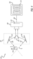
- Figure 4 shows a view of an alternate example 200 of the beam quality measurement apparatus 100 shown in Figures 1 and 2 .
- at least one beam 202 may traverse at least one sampling region 230 and may be positioned so that it intersects focal plane P y , but not focal plane P x .
- the beam 202 includes one or more beam waists 228, though those skilled in the art will appreciate that the beam 202 need not include a beam waist 228. If the beam 202 is offset from or is not parallel to one or both focal planes, the beam 202 may be observed as being out of focus over some or all of its extent.
- one or more scattered light signals 220 and 222 may be directed by at least one optical system 250 to one or more image sensors 218 positioned in at least one imaging device 204.
- the optical system 250 includes at least one reflecting surface 252 and at least one optical element 254, although those skilled in the art will appreciate that any variety of optical elements and components may be used in the optical system 250.
- the optical system 250 comprises two reflecting surfaces 252 and 256. Alternative components for use in the optical system 250 are described above with respect to optical system 150.
- Figures 5A and 5B show images 234a and 234b as captured by the imaging device 204, directed by at least one conduit 206 to the image processing module 208 and processed by the image processing module 208 and shown on the display 216.
- the beam 202 may intersect the focal plane P y , and the image 234a may be observed to be in focus.
- Figure 5A shows at least one image 234a of at least one beam caustic 226a of the beam 202 relating to focal plane P y captured by the imaging device 204 as the beam 202 propagates through the sampling region 230.
- the image processing module 208 may generate one or more slices 270, 272 and 274 by scanning the image 234a with at least one cursor 224a at cursor positions 260, 262 and 264 respectively.
- the image processing module 208 may be configured to analyze the image to determine at least one axis B 1 and to use that data to compute the distance d from a point on B 1 corresponding to each slice to the focal plane P x , whose position is known. For example, once the axis B 1 is defined, the distance d from the center of slice 270 to the focal plane P x is computed and denoted d 270 .
- the image processing module 208 uses the location of axis B 1 at each slice, assigning the values of the distances d 270 , d 272 and d 274 from each respective slice. As described below, this distance data is used to deconvolve each slice using the transfer function corresponding to that distance, and reassemble the deconvolved slices into an image that can be used to compute the correct beam parameters of the beam 202.
- the display 216 of the image processing module 208 shows at least one image 234b of the beam caustic 226a of the beam 202 relating to focal plane P x , captured by the imaging device 204 as the beam 202 propagates through the sampling region 230.
- the image processing module 208 may generate slices 290, 292 and 294 of the beam image 234b with at least one cursor 224b at cursor positions 280, 282 and 284 respectively.
- the image 234b and slices 290, 292 and 294 may be observed as being out of focus, causing the image 234b to appear blurry.
- the image of the beam waist 228b captured in slice 294 at cursor position 284 may appear smaller or larger than it should be.
- the blurry appearance of the image 234b may cause the laser beam quality measurement system to yield incorrect beam parameter results.
- the image processing module 208 may be configured to correct for the blur of the image 234b by using the distances d 270 , d 272 , d 274 , etc. calculated from the image 234a to determine at least one out-of-focus transfer function G( ⁇ ,d) for each slice, which is used in combination with the known modulation transfer function H( ⁇ ) of the system to deconvolve each slice.
- the images formed by reassembling the deconvolved slices can then be analyzed to compute the correct beam parameters described above.
- any combination of beam measurements or processing algorithms may be used to correct the focus errors caused by the axis of the beam 202 not being coincident with the focal planes of the apparatus 200.
- Figures 6 and 7A-7B show various images of alternate view 300 of the beam quality measurement apparatus shown in Figures 1 and 2 where at least one beam 302 traverses at least one sampling region 330 and is positioned such that it intersects but may not be parallel to at least one of focal planes P y and P x .
- the beam 302 may include one or more beam waists 328, though those skilled in the art will appreciate that the beam 302 need not have a beam waist 328.
- one or more scattered light signals 320 and 322 scattered from the beam 302 may be directed by at least one optical system 360 to one or more image sensors 318 positioned in at least one imaging device 304.
- the optical system 360 includes at least one reflecting surface 362 and at least one optical element 364, although those skilled in the art will appreciate that any variety of optical elements and components may be used in the optical system 360.
- the optical system 360 comprises two reflecting surfaces 362 and 366. Alternative components for use in the optical system 360 are described above with respect to optical system 150.
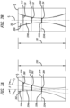
- Figure 7A shows at least one image 334a of at least one beam caustic 326a of the beam 302 relating to focal plane P y , as captured by the image sensor 318 of the imaging device 304 (shown in Figure 6 ) as the beam 302 propagates through the sampling region 330 and is directed by at least one conduit 306 to at least one image processing module 308.
- the image processing module 308 may generate slices 380, 382 and 384 by scanning the image 334a with at least one cursor 324a at cursor positions 370, 372 and 374 respectively.
- the image processing module 308 may analyze the image to define an axis C 1 that is shown as slanted at angle ⁇ relative to the focal plane P x , but the image 334a otherwise may be observed to be in focus.
- Figure 7B shows an image 334b of at least one beam caustic 326b of the beam 302 relating to focal plane P x , captured by the imaging device 304 and processed by the image processing module 308.
- the image processing module 308 may generate slices 350, 352, 354 by scanning the image 334b with at least one cursor 324b at locations 340, 342 and 344 respectively.
- the beam 302 may intersect focal plane P x only at the beam waist 328b, only the beam waist 328b may be observed to be in focus, and the remainder of the image 334b may be observed to be out of focus.
- the beam 302 may intersect focal planes P y and P x at a variety of angles, or the beam 302 may intersect neither focal plane P y and P x
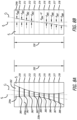
- Figures 8A and 8B show various views of image 334a of the beam 302 as shown on the display 316.
- Figure 8A shows the image 334a as shown in Figure 7A , with slices 380-388 generated by the image processing module 308 by scanning the image 334a with cursor 324a at cursor positions 370-378.
- the image processing module 308 analyzes the image 334a to define the optical axis C 1 .
- the image processing module 308 may analyze multiple images to define any number of optical axes.
- distances d 380 through ensemble from the optical axis C 1 to the image plane P x may be calculated for each slice 380-388 by the image processing module 308. As described below, this data may then be used to remove the out-of-focus blur of the image 334b shown in Figures 7B and 9A .
- the out of focus blur may be corrected by applying a variety of optical or signal processing methods to the images of the beam 302.
- Figures 7A-7B , 8A-8B and 9A-9C show the progression of image 334b shown in Figure 7B from being out of focus to being in focus, as displayed on the display 316.
- Figure 7B shows an image 334b of the beam caustic 326b as captured by the imaging device 304 and processed by the image processing module 308.
- the image processing module 308 may generate slices 350-358 by scanning the image 334b with at least one cursor 324b at locations 340-348. Those skilled in the art will appreciate that the image processing module 308 may capture any number of slices at any number of positions along the sampling region 330. Because the beam 302 is not parallel to the focal plane P x , one or more of the slices 350-358 may appear out of focus.
- the beam waist 328b at cursor position 344 intersects the focal plane, the beam waist 328b may be observed to be in focus, though those skilled in the art will appreciate that the beam waist 328b may not be in focus, and a different location of the beam may be in focus instead.
- slices 355-358 and 353-350 may become progressively more out-of-focus the further they are from the beam waist position 344.
- the distances d 380 through ensemble from the center of slices 380-388 to the optical axis C 1 as shown in Figures 8A and 8B as described above are used to deconvolve each slice 380-388 using the in-focus transfer function H( ⁇ ) and the out-of-focus transfer function G( ⁇ ,d) corresponding to that distance, and reassemble the deconvolved slices into an image 334c shown in Figure 9C with slices 390-398 that can be used to compute the correct beam parameters such as beam divergence and beam propagation ratio M 2 as described above.
- Figures 10-13 show views of an alternate beam quality measurement apparatus 400 configured with multiple imaging devices.
- the laser beam quality measurement apparatus 400 may comprise at least two imaging devices 404 and 406 that may be in optical communication with at least one beam 402 propagating through at least one sampling region 430.
- the imaging devices 404 and 406 may be configured to capture one or more light signals 420 and 422 scattered from the beam 402 and direct them via at least two conduits 410 and 412, respectively, to at least one image processing module 408.
- Exemplary types of conduits 106 include, without limitation, electrical cables (such as USB, FireWire, CATS), fiber optic cables or digital optical cables.
- the conduit 106 may comprise network or wireless communication protocols such as GigE Ethernet, Bluetooth, WiFi and the like.
- the imaging processing module 408 may be configured to process the signals 420 and 422 and display one or more beam images 434 on one or more displays 416.
- the imaging devices 404 and 406 may further comprise at least one image sensor 414 and 418, respectively.
- the imaging devices 404 and 406 are cameras with at least one CMOS image sensors 414, 418 disposed therein.
- the image sensors 414, 418 may comprise charge-coupled device (CCD) image sensors, focal plane arrays, pyroelectric arrays, scanning arrays, time-delay integration imagers and the like.
- CCD charge-coupled device
- the imaging devices 404 and 406 are separated by at least one angle ⁇ .
- angle ⁇ may be 90°, making the imaging devices orthogonal to each other in at least one plane.
- angle ⁇ may be anywhere between 1 and 179 degrees.
- the image processing module 408 may analyze the images 434 shown in the display 416 to compute various beam parameters.
- Figure 11 shows an alternate view of the laser beam quality measurement apparatus 400 shown in Figure 10 .
- the imaging devices 406 and 404 may define focal planes P y and P x , respectively, oriented orthogonal to each other, although those skilled in the art will appreciate that focal planes P y and P x may not be orthogonal to each other.
- the imaging devices 404 and 406 may define a single focal plane or more than two focal planes that may intersect at a variety of angles.
- the beam 402 is shown end-on, intersecting the focal planes P y and P x , as though it were entering or exiting the surface of the page.
- the beam 402 propagates along the intersection of focal planes P y and P x .
- the display 416 shows images 434a and 434b relating to the focal planes P y and P x , respectively, as captured by imaging devices 406 and 404 respectively.
- the display 416 may show a single image or any number of images 434.
- the images 434a and 434b displayed on display device 416 are substantially similar and may be observed to be in focus. In this embodiment, because both images 434a and 434b are in focus, no focus correction is required.
- the image processing module 408 may use the images 434a and 434b to compute a set of beam parameters such as beam waist size, location or focal shift, Rayleigh range, beam centroid, angular divergence, beam parameter product and the M 2 beam propagation ratio, and the like, that the operator may use to characterize and control performance of the laser or light source 10 shown in Figure 1 .
- beam parameters such as beam waist size, location or focal shift, Rayleigh range, beam centroid, angular divergence, beam parameter product and the M 2 beam propagation ratio, and the like, that the operator may use to characterize and control performance of the laser or light source 10 shown in Figure 1 .
- beam parameters such as beam waist size, location or focal shift, Rayleigh range, beam centroid, angular divergence, beam parameter product and the M 2 beam propagation ratio, and the like
- Figure 12 shows an alternate view of the laser beam quality measurement apparatus 400 shown in Figure 10 .
- the beam 402 may traverse at least one sampling region 430 and may be positioned so that it intersects focal plane P y , but not focal plane P x . If the beam 402 is offset from or is not parallel to one or both focal planes, the beam 402 may be observed as being out of focus over some or all of its extent.
- display 416 shows images 444a and 444b as captured by the imaging devices 406 and 404, respectively, and processed by the image processing module 408. As shown in Figure 12 , because the beam 402 intersects the focal plane P y , the image 444a may be observed to be in focus.
- the image processing module 408 may generate one or more slices 470, 472 and 474 by scanning the image 444a with at least one cursor 424a various positions along the image 444a. Those skilled in the art will appreciate that any number of slices may be generated by the image processing module 408.
- the image processing module 408 may be configured to analyze images 444a and 444b to determine at least one axis B 1 and to use that data to compute the distance d from the center of each slice 470-474 to the focal plane P x , whose position is known.
- the image processing module 408 may also be configured to determine the distance d from the center of each slice 470-474 to the focal plane P y .
- the values of the distances d 470 , d 472 and d 474 from the center of their respective slices to the axis P x is used to deconvolve each slice using the transfer function corresponding to that distance, and reassemble the deconvolved slices into a corrected image relating to focal plane P x that can be used to compute the correct beam parameters of the beam 402.
- Figure 13 shows an alternate view of the laser beam quality measurement apparatus 400 shown in Figure 10 .
- the beam 402 traverses at least one sampling region 430 and is positioned such that it intersects but may not be parallel to at least one of focal planes P y and P x .
- display 416 shows images 454a (relating to focal plane P y ) and 454b (relating to focal plane P x ) as captured by the imaging devices 406 and 404, respectively, and processed by the image processing module 408.
- the image 454a appears slanted at an angle relative to focal plane P x but otherwise may be observed to be in focus.
- Image 454b appears to be focused only at the beam waist 428b.
- the method of correction of the image 454b may be similar to that applied to image 334b shown above in Figures 6 , 7A-7B , 8A-8B and 9A-9C.
- the image processing module 408 may generate slices 480-488 by scanning the image 454a with cursor 455a.
- the image processing module 408 may analyze the image to define an axis C 1 .
- the image processing module 408 may analyze any number of images to define any number of optical axes.
- the image processing module 408 may generate slices 490-498 by scanning the image 454b with cursor 455b.
- the beam 402 may intersect focal planes P y and P x at a variety of angles, or the beam 402 may intersect neither focal plane P y and P x .
- the image processing module 408 may compute the distances d 480 through d 488 from the center of slices 480-488 to the optical axis C 1 and use them to deconvolve each slice 490-498 using the in-focus transfer function H( ⁇ ) and the out-of-focus transfer function G( ⁇ ,d) corresponding to each distance, and reassemble the deconvolved slices into an image 454c shown in Figure 13 that can be used to compute the correct beam parameters such as beam divergence and beam propagation ratio M 2 as described above.
- the out of focus blur may be corrected by applying a variety of optical or signal processing methods to the images of beam 402.
- Figure 14 shows an embodiment of a beam quality measurement apparatus 500 where a single imaging device 504 may be configured to be repositionable from a first position T 1 to a second position T 2 , thereby allowing multiple images to be acquired at multiple angular focal planes.
- the imaging device 504 may be in optical communication with and configured to receive one or more scattered light signals 520 and 522 from at least one beam 502 propagating through at least one sampling region 530.
- the imaging device 504 may be repositioned from position T 1 to position T 2 to collect one or more scattered light signals 520 and 522.
- the imaging device 504 may be configured to direct the images of scattered light signals 520 and 522 via at least one conduit 506 to at least one image processing module 512 that may be configured to process the signals and display one or more images on one or more displays 516.
- the image processing module 512 may analyze the images shown in the display 516 to compute various beam parameters.
- the focus correction methods described above may be used to correct for out-of-focus images for the beam 502 due to misalignment of the beam relative to focal planes P y and P x .
Landscapes
- Physics & Mathematics (AREA)
- General Physics & Mathematics (AREA)
- Spectroscopy & Molecular Physics (AREA)
- Optics & Photonics (AREA)
- Electromagnetism (AREA)
- Engineering & Computer Science (AREA)
- Plasma & Fusion (AREA)
- Investigating Or Analysing Materials By Optical Means (AREA)
- Length Measuring Devices By Optical Means (AREA)
- Photometry And Measurement Of Optical Pulse Characteristics (AREA)
- Lasers (AREA)
Description
- The present application claims priority to
U.S. Provisional Patent application Ser. No. 62/701,244 - entitled "Method and Apparatus for Focus Correction of Multi-Image Laser Beam Quality Measurements," filed on July 20, 2018 - High power lasers are being used increasingly in materials processing applications. Understanding the performance parameters of the laser beam provides important insight into process control and process improvements. Laser beam profilers are used for this purpose. One technique used to measure the quality of a focused laser beam is to acquire multiple images of the Rayleigh scatter of the beam, then process those images digitally to compute parameters such as beam waist size, beam centroid, angular divergence and M2 beam propagation ratio and the like. A laser beam profiler apparatus that measures Rayleigh scattering is described in
US patent 8,988,673 issued March 24, 2015 and assigned to Ophir-Spiricon, LLC. - The publication "Scattered light imaging method (SLIM) for characterization of arbitrary laser beam intensity profiles" by K. Jorge et al., Applied Optics, Vol. 53 No. 20, p. 4556, 10 July 2014 (XP001590773), discloses a laser beam characterization method based on scattered light imaging of a laser beam.
- While prior art laser beam profilers have proven useful in the past, some shortcomings have been identified. For instance, the laser beam being measured may not completely overlap the focal planes of the imaging devices of the laser beam profiler. This may produce focal errors that can lead to erroneous beam characterization results. As such, there is an ongoing need for a method and apparatus that detects and compensates for the focal errors.
- The present application discloses a method of focus correction of at least one image of a laser beam measurement system in order to accurately compute a wide variety of beam parameters. Exemplary beam parameters include beam waist size and location, beam centroid, Rayleigh range, angular divergence, beam parameter product, and M2 beam propagation ratio. While the description included herewith discusses methods of correcting for focus errors, those skilled in the art will appreciate that a variety of methods may be used to measure and correct for various characteristics of laser beam measurements. Additionally, the focus correction methods described herein may be used with a variety of light beams.
- The invention relates to a method defined in claim 1.
- Other features and benefits of the method and apparatus for focus correction for multi-image laser beam quality measurements as disclosed will become apparent from a consideration of the following detailed description.
- Various illustrations of a method and apparatus for focus correction for multi-image laser beam quality measurements will be explained in more detail by way of the accompanying drawings, wherein:
-
Figure 1 shows a laser beam quality measurement apparatus for use with a focus correction method; -
Figure 2 shows a view of the laser beam quality measurement apparatus for use with a focus correction method shown inFigure 1 where the laser beam intersects at least two focal planes; -
Figures 3A and 3B show images of the beam caustics of the laser beam as captured by the laser beam quality measurement apparatus relative to the focal planes shown inFigure 2 for use with a focus correction method; -
Figure 4 shows an alternate view of the laser beam quality measurement apparatus shown inFigure 1 where the laser beam intersects only one focal plane; -
Figures 5A and 5B show images of the beam caustics of the laser beam as captured by the laser beam quality measurement apparatus relative to the focal planes shown inFigure 4 for use with a focus correction method; -
Figure 6 shows an alternate view of the laser beam quality measurement apparatus shown inFigure 1 where the laser beam intersects two focal planes at an angle; -
Figures 7A and 7B show images of the beam caustics of the laser beam as captured by the beam quality measurement apparatus relative to the focal planes shown inFigure 6 ; -
Figures 8A and 8B show images of the beam caustic shown inFigure 7A showing slices sampled along the beam image relative to focal plane Py for use with an embodiment of the focus correction method; -
Figures 9A-9C show images of the beam caustic shown inFigure 7B showing slices sampled along the beam image relative to focal plane Px, and the resulting correction with an embodiment of the focus correction method; -
Figure 10 shows an alternate laser beam quality measurement apparatus using multiple imaging devices for use with the focus correction method; -
Figure 11 shows a view of the laser beam quality measurement apparatus shown inFigure 10 where the laser beam intersects two focal planes; -
Figure 12 shows a view of the laser beam quality measurement apparatus shown inFigure 10 where the laser beam intersects one focal plane; -
Figure 13 shows a view of the laser beam quality measurement apparatus shown inFigure 10 where the laser beam intersects two focal planes at an angle; and -
Figure 14 shows an alternate laser beam quality measurement apparatus for use with the focus correction method using a single imaging device that may be moved between multiple positions allowing multiple images to be acquired at multiple angular focal planes. - Generally, optical systems that are out of focus have a distinct two-dimensional point spread function or transfer function. For small point spread functions where the image changes slowly in one dimension, these functions can be approximated by a set of simpler one-dimensional line spread functions or modulation transfer functions. In the embodiments described below, the two-dimensional point spread function is approximated by simpler one-dimensional line spread functions that may be applied to one slice of an image at a time.
- In the embodiments described below, the modulation transfer function for out-of-focus images may be characterized a priori, either mathematically or empirically. This out-of-focus modulation transfer function is denoted G(ξ,d) where ξ represents the spatial frequency and d represents the distance of the object from the focal plane. In the illustrated embodiment, the laser beam quality measurement apparatus may comprise an imaging device and optical system that have a modulation transfer function denoted H(ξ) that may also be characterized a priori by a variety of methods.
- In the embodiments described below, images of the beams are deconstructed slice by slice. An approximation of each slice of the image captured by the imaging devices described above may be y(x) = b(x)*g(x,d)*h(x) where x is the pixel location in each slice, y(x) is one slice of the camera image, b(x) is the profile of the beam for that slice, and g(x,d) and h(x) are the spatial domain equivalents of G(ξ,d) and H(ξ) respectively, where the asterisk denotes convolution. To find an estimate of b(x), the distance of the beam from the focal plane for a given slice of the image needs to be determined. That distance, d, can be used to find the composite line spread function by convolving g(x,d) with h(x). When this is done, the resulting function may be used to deconvolve y(x), the given slice of camera image. For digital cameras, y(x) will be discrete, yielding accurate results if y(x) is effectively band limited to spatial frequencies below the Nyquist frequency as described below. In practice, b(x), g(x,d) and h(x) are considered to be discrete as well. An alternate expression of the transfer function needed for deconvolution may be G(ξ,d)H(ξ), which is the Fourier transform of g(x,d)*h(x). This allows the earlier equation to be written equivalently as Y(ξ) = B(ξ)G(ξ,d)H(ξ). In another alternate method, at least one noise term n(x) may be added such that the approximation of each slice may be y(x) = b(x)*g(x,d)*h(x)+n(x) or Y(ξ) = B(k)G(k,d)H(k)+N(k).
- Alternatively, the deconvolution can be implemented in two dimensions, which is an approach widely used with focal correction. The two-dimensional point spread function (or impulse responses) h(x,y) and g(x,y,d) may be computed once their one-dimensional modulation transfer functions are known, and they may be used for the two-dimensional deconvolution. Generally, the computing requirements for this approach are significant, and for the purpose of imaging laser beams that do not change rapidly slice to slice, a one-dimensional deconvolution may suffice. Those skilled in the art will appreciate that a number of alternative methods for processing image data may be employed to correct for beam focus errors.
- Simply put, the method for focus correction of laser beam quality measurements involves 1) capturing images of the beam and from them determining the axis of the beam in three dimensions, 2) dividing each image into multiple slices, 3) finding the distance from the beam axis to the focal plane for each slice of each image, 4) deconvolving each slice using the transfer function corresponding to that distance, and 5) reassembling the deconvolved slices into an image that can be used to compute beam parameters.
-
Figure 1 shows a laser beamquality measurement apparatus 100. As shown, the apparatus may comprise at least onehousing 101 with one ormore imaging devices 104 positioned therein and in optical communication with at least onesampling region 130. One or moreoptical systems 150 may be in optical communication with thesampling region 130 and theimaging device 104. Alternatively, the laser beamquality measurement apparatus 100 need not include anoptical system 150. Further, any number of additional imaging or measurement devices and/or sensors may be used with the laser beamquality measurement apparatus 100. As shown, at least one laser orlight source 10 may direct at least onebeam 102 into and/or through thesampling region 130. Those skilled in the art will appreciate that thelight source 10 may comprise light emitting diodes, superluminescent diodes, flashlight beams and the like. Theimaging device 104 andoptical system 150 may be configured to capture one or more light signals from thelaser beam 102 and direct them via at least oneconduit 106 to at least oneimage processing module 108. In one embodiment, theimaging device 104 andoptical system 150 may be configured to capture one or more light signals that are Rayleigh scattered from thebeam 102, although those skilled in the art will appreciate that Raman scattering or any variety of scattering effects or other optical phenomena may be observed by the laser beam quality measurement system. - Referring again to
Figure 1 , theimage processing module 108 may be configured to process at least one scattered light signal and display one or more images on one ormore displays 116. As shown, thebeam 102 may have one or more focal points orbeam waists 128 as it propagates through thesampling region 130. In the illustrated embodiment, the beam waist orfocal point 128 may be defined as the location or region where the beam is most tightly focused or where the cross section of the beam is the smallest or where the beam power or optical fluence is most highly concentrated. In many material processing applications, the user may locate the beam waist on the surface of or within the material to be processed, though those skilled in the art will appreciate that that the beam waist may be positioned at a variety of positions relative to the material to be processed. In one embodiment, thehousing 101, theoptical system 150 and theimaging device 104 may define one or more focal planes. In the illustrated embodiment, thehousing 101, theoptical system 150 and theimaging devices 104 define two focal planes, Py and Px, and at least one plane Z, although those skilled in the art will appreciate that any number of housings or imaging devices may be used that define any number of planes or focal planes. In the illustrated embodiment, plane Z is substantially orthogonal to the image planes PY and Px, though in another embodiment plane Z may not be orthogonal to the image planes Py and Px. Optionally, the operator may use at least onealignment device 110 to align thebeam 102 within thesampling region 130 such that thebeam 102 substantially intersects both focal planes, Px and Py, although those skilled in the art will appreciate that the use of such an alignment device is not required. -
Figures 2 and3A-3B show various views of the embodiment of the laser beamquality measurement apparatus 100 shown inFigure 1 , as looking through plane Z. As shown, one or morelight signals beam 102 may be directed to theimaging device 104 via theoptical system 150. In the illustrated embodiment the light signals 120 and 122 are Rayleigh-scattered from thebeam 102. Those skilled in the art will appreciate that any number of light signals scattered in a variety of ways may be measured. In the illustrated embodiment, theoptical system 150 and theimaging device 104 define focal planes Py and Px oriented orthogonal to each other, although those skilled in the art will appreciate that focal planes Py and Px may not be orthogonal to each other. Optionally, theoptical system 150 and theimaging device 104 may define a single focal plane or more than two focal planes that may intersect at a variety of angles. In short, any number of focal planes may be defined by theoptical system 150 and/or theimaging device 104. As shown inFigure 2 , thebeam 102 is shown end-on, intersecting the focal planes Py and Px, as though it were entering or exiting the plane Z as the surface of the page. Theoptical system 150 may comprise at least one reflectingsurface 152 and at least oneoptical element 154, although those skilled in the art will appreciate that any variety of optical elements and components may be used in theoptical system 150. In the illustrated embodiment, theoptical system 150 comprises two reflectingsurfaces 152 and 156. In the illustrated embodiment, reflectingsurfaces 152 and 156 are planar mirrors. Optionally, the reflectingsurfaces 152, 156 may be a dielectric mirrors, replicated mirrors, concave mirrors, convex mirrors, and the like. Also, the reflectingsurfaces 152, 156 could be a grating, such as echelle gratings, holographic gratings, volume holographic gratings, volume Bragg gratings, and the like. In the illustrated embodiment, theoptical element 154 is a prism. Optionally, theoptical element 154 may be a beamsplitter, mirror, or other reflective or refractive optic. Those skilled in the art will appreciate that theoptical system 150 may comprise any combination of reflecting surfaces, refractive optics, lenses, collimators, filters, spatial filters, irises, stops, and the like. As shown, the scattered light signals 120 and 122 are reflected by the reflectingsurfaces 152 and 156 respectively and are directed by theoptical element 154 to theimaging device 104. Theimaging device 104 may comprise at least oneimage sensor 118 located therein. In the illustrated embodiment, theimaging device 104 is a camera with at least oneCMOS image sensor 118 located therein. Optionally, theimage sensor 118 may be a charge-coupled device (CCD) image sensor, focal plane array, pyroelectric array, scanning array, time-delay integration imager and the like. Those skilled in the art will appreciate that a wide variety of image sensors, imaging devices or imaging systems may be used with theapparatus 100. Also, those skilled in the art will appreciate that rather than using a single imaging device, multiple imaging devices may be used, or theimaging device 104 may be repositionable during use. Also, the scattered light signals 120 and 122 may be collected by an alternative optical system such as a fiber bundle, an elliptical reflector, or a parabolic reflector that may direct the scattered light signals 120, 122 to theimaging device 104.Figures 10-13 described below show various views of alternate embodiments using multiple imaging devices as described herein, wherein similar reference numbers refer to similar components. In the alternative,Figure 14 shows an embodiment where a single imaging device is used and the imaging device is repositionable from a first position T1 to a second position T2, thereby allowing multiple images to be acquired at multiple angles, each image with its own focal plane. - As shown in
Figure 2 , theimaging device 104 may be connected to at least oneimage processing module 108 via at least oneconduit 106. Exemplary types ofconduits 106 include, without limitation, electrical cables (such as USB, FireWire, CATS), fiber optic cables or digital optical cables. Optionally, theconduit 106 may comprise network or wireless communication protocols such as GigE Ethernet, Bluetooth, WiFi and the like. Theimage processing module 108 may comprise at least onedisplay 116. Exemplary types ofdisplays 116 include, without limitation, computer graphics or graphical user interfaces that are displayed on flat-screen, LED or LCD monitors and the like. -
Figures 3A and 3B show images display 116. Optionally, thedisplay 116 may show a single image or any number of images 134. As shown inFigure 2 , in the illustrated embodiment, thebeam 102 propagates along the intersection of focal planes Py and Px.Figure 3A shows at least oneimage 134a of at least one beam caustic 126a relating to focal plane Py captured by theimaging device 104 as thebeam 102 is aligned so that it propagates through thesampling region 130. Theimage processing module 108 may generate one or more slices of theimage 134a by scanning theimage 134a with one ormore cursors 124a. For example, slices 170, 172 and 174 may be captured at one ormore cursor positions image processing module 108. Theimage 134a may exhibit at least onebeam waist 128a that is shown approximately in the center of thesampling region 130. Alternatively, thebeam waist 128a may be anywhere in theimage 134a. -
Figure 3B of the illustrated embodiment shows at least oneimage 134b of at least one beam caustic 126b relating to focal plane Px captured by theimaging device 104 as the beam propagates through thesampling region 130. In the illustrated embodiment, theimage processing module 108 may generate one ormore slices beam image 134a by scanning theimage 134a with at least onecursor 124a at one ormore cursor positions images Figures 3A and 3B are substantially identical, exhibiting one ormore edges image processing module 108 may use theimages Figures 3A and 3B to compute a set of beam parameters such as beam waist size, location or focal shift, Rayleigh range, beam centroid, angular divergence, beam parameter product and the M2 beam propagation ratio, and the like, that the operator may use to characterize and control performance of the laser orlight source 10 shown inFigure 1 . Those skilled in the art will appreciate that any number of beam parameters or characteristics of thebeam 102 may be computed. -
Figure 4 shows a view of an alternate example 200 of the beamquality measurement apparatus 100 shown inFigures 1 and2 . In this example, at least onebeam 202 may traverse at least onesampling region 230 and may be positioned so that it intersects focal plane Py, but not focal plane Px. In the illustrated example, thebeam 202 includes one ormore beam waists 228, though those skilled in the art will appreciate that thebeam 202 need not include abeam waist 228. If thebeam 202 is offset from or is not parallel to one or both focal planes, thebeam 202 may be observed as being out of focus over some or all of its extent. As shown, one or more scatteredlight signals optical system 250 to one ormore image sensors 218 positioned in at least oneimaging device 204. As described above, many types ofimage sensors 218 may be used in theimaging device 204. In the illustrated example, theoptical system 250 includes at least one reflectingsurface 252 and at least oneoptical element 254, although those skilled in the art will appreciate that any variety of optical elements and components may be used in theoptical system 250. In the illustrated example, theoptical system 250 comprises two reflectingsurfaces optical system 250 are described above with respect tooptical system 150. -
Figures 5A and 5B show images imaging device 204, directed by at least oneconduit 206 to theimage processing module 208 and processed by theimage processing module 208 and shown on thedisplay 216. As shown inFigures 4 and5A , thebeam 202 may intersect the focal plane Py, and theimage 234a may be observed to be in focus.Figure 5A shows at least oneimage 234a of at least one beam caustic 226a of thebeam 202 relating to focal plane Py captured by theimaging device 204 as thebeam 202 propagates through thesampling region 230. In the illustrated embodiment, for example, theimage processing module 208 may generate one ormore slices image 234a with at least onecursor 224a atcursor positions image processing module 208. In the illustrated embodiment, theimage processing module 208 may be configured to analyze the image to determine at least one axis B1 and to use that data to compute the distance d from a point on B1 corresponding to each slice to the focal plane Px, whose position is known. For example, once the axis B1 is defined, the distance d from the center ofslice 270 to the focal plane Px is computed and denoted d270. Theimage processing module 208 then uses the location of axis B1 at each slice, assigning the values of the distances d270, d272 and d274 from each respective slice. As described below, this distance data is used to deconvolve each slice using the transfer function corresponding to that distance, and reassemble the deconvolved slices into an image that can be used to compute the correct beam parameters of thebeam 202. - Referring to
Figures 4 andFigure 5B of the illustrated embodiment, thedisplay 216 of theimage processing module 208 shows at least oneimage 234b of the beam caustic 226a of thebeam 202 relating to focal plane Px, captured by theimaging device 204 as thebeam 202 propagates through thesampling region 230. As shown inFigure 5B , theimage processing module 208 may generateslices beam image 234b with at least onecursor 224b atcursor positions beam 202 is offset from focal plane Px, theimage 234b andslices image 234b to appear blurry. Also, the image of thebeam waist 228b captured inslice 294 atcursor position 284 may appear smaller or larger than it should be. The blurry appearance of theimage 234b may cause the laser beam quality measurement system to yield incorrect beam parameter results. However, theimage processing module 208 may be configured to correct for the blur of theimage 234b by using the distances d270, d272, d274, etc. calculated from theimage 234a to determine at least one out-of-focus transfer function G(ξ,d) for each slice, which is used in combination with the known modulation transfer function H(ξ) of the system to deconvolve each slice. The images formed by reassembling the deconvolved slices can then be analyzed to compute the correct beam parameters described above. Those skilled in the art will appreciate that any combination of beam measurements or processing algorithms may be used to correct the focus errors caused by the axis of thebeam 202 not being coincident with the focal planes of theapparatus 200. -
Figures 6 and7A-7B show various images ofalternate view 300 of the beam quality measurement apparatus shown inFigures 1 and2 where at least onebeam 302 traverses at least onesampling region 330 and is positioned such that it intersects but may not be parallel to at least one of focal planes Py and Px. In the illustrated embodiment, thebeam 302 may include one ormore beam waists 328, though those skilled in the art will appreciate that thebeam 302 need not have abeam waist 328. As shown inFigure 6 , one or more scatteredlight signals beam 302 may be directed by at least oneoptical system 360 to one ormore image sensors 318 positioned in at least oneimaging device 304. As described above, many types ofimage sensors 318 may be used in theimaging device 304. In the illustrated embodiment, theoptical system 360 includes at least one reflectingsurface 362 and at least oneoptical element 364, although those skilled in the art will appreciate that any variety of optical elements and components may be used in theoptical system 360. In the illustrated embodiment, theoptical system 360 comprises two reflectingsurfaces optical system 360 are described above with respect tooptical system 150.Figure 7A shows at least oneimage 334a of at least one beam caustic 326a of thebeam 302 relating to focal plane Py, as captured by theimage sensor 318 of the imaging device 304 (shown inFigure 6 ) as thebeam 302 propagates through thesampling region 330 and is directed by at least oneconduit 306 to at least oneimage processing module 308. In the illustrated embodiment, theimage processing module 308 may generateslices image 334a with at least onecursor 324a atcursor positions image processing module 308 may analyze the image to define an axis C1 that is shown as slanted at angle β relative to the focal plane Px, but theimage 334a otherwise may be observed to be in focus.Figure 7B shows animage 334b of at least one beam caustic 326b of thebeam 302 relating to focal plane Px, captured by theimaging device 304 and processed by theimage processing module 308. Theimage processing module 308 may generateslices image 334b with at least onecursor 324b atlocations beam 302 may intersect focal plane Px only at thebeam waist 328b, only thebeam waist 328b may be observed to be in focus, and the remainder of theimage 334b may be observed to be out of focus. Those skilled in the art will appreciate that thebeam 302 may intersect focal planes Py and Px at a variety of angles, or thebeam 302 may intersect neither focal plane Py and Px -
Figures 8A and 8B show various views ofimage 334a of thebeam 302 as shown on thedisplay 316. In the illustrated embodiment,Figure 8A shows theimage 334a as shown inFigure 7A , with slices 380-388 generated by theimage processing module 308 by scanning theimage 334a withcursor 324a at cursor positions 370-378. Those skilled in the art will appreciate that many more slices may be created and analyzed by theimage processing module 308 to provide increased resolution. As shown inFigures 8A and 8B , theimage processing module 308 analyzes theimage 334a to define the optical axis C1. Optionally, theimage processing module 308 may analyze multiple images to define any number of optical axes. For example, in the illustrated embodiment, once the optical axis C1 is defined, distances d380 through dass from the optical axis C1 to the image plane Px (whose position is known) may be calculated for each slice 380-388 by theimage processing module 308. As described below, this data may then be used to remove the out-of-focus blur of theimage 334b shown inFigures 7B and9A . Those skilled in the art will appreciate that the out of focus blur may be corrected by applying a variety of optical or signal processing methods to the images of thebeam 302. -
Figures 7A-7B ,8A-8B and9A-9C show the progression ofimage 334b shown inFigure 7B from being out of focus to being in focus, as displayed on thedisplay 316.Figure 7B shows animage 334b of the beam caustic 326b as captured by theimaging device 304 and processed by theimage processing module 308. Theimage processing module 308 may generate slices 350-358 by scanning theimage 334b with at least onecursor 324b at locations 340-348. Those skilled in the art will appreciate that theimage processing module 308 may capture any number of slices at any number of positions along thesampling region 330. Because thebeam 302 is not parallel to the focal plane Px, one or more of the slices 350-358 may appear out of focus. In this embodiment, because thebeam waist 328b atcursor position 344 intersects the focal plane, thebeam waist 328b may be observed to be in focus, though those skilled in the art will appreciate that thebeam waist 328b may not be in focus, and a different location of the beam may be in focus instead. In contrast to theslice 354 at the beam waist, for example, slices 355-358 and 353-350 may become progressively more out-of-focus the further they are from thebeam waist position 344. The distances d380 through dass from the center of slices 380-388 to the optical axis C1 as shown inFigures 8A and 8B as described above are used to deconvolve each slice 380-388 using the in-focus transfer function H(ξ) and the out-of-focus transfer function G(ξ,d) corresponding to that distance, and reassemble the deconvolved slices into animage 334c shown inFigure 9C with slices 390-398 that can be used to compute the correct beam parameters such as beam divergence and beam propagation ratio M2 as described above. -
Figures 10-13 show views of an alternate beamquality measurement apparatus 400 configured with multiple imaging devices. As shown inFigures 10 and11 , the laser beamquality measurement apparatus 400 may comprise at least twoimaging devices beam 402 propagating through at least onesampling region 430. Theimaging devices light signals beam 402 and direct them via at least twoconduits image processing module 408. Those skilled in the art will appreciate that a single conduit may be used. Exemplary types ofconduits 106 include, without limitation, electrical cables (such as USB, FireWire, CATS), fiber optic cables or digital optical cables. Optionally, theconduit 106 may comprise network or wireless communication protocols such as GigE Ethernet, Bluetooth, WiFi and the like. Theimaging processing module 408 may be configured to process thesignals more displays 416. Theimaging devices image sensor imaging devices CMOS image sensors image sensors apparatus 400. As shown inFigure 10 , theimaging devices image processing module 408 may analyze the images 434 shown in thedisplay 416 to compute various beam parameters. -
Figure 11 shows an alternate view of the laser beamquality measurement apparatus 400 shown inFigure 10 . In the illustrated example, theimaging devices imaging devices Figure 11 , thebeam 402 is shown end-on, intersecting the focal planes Py and Px, as though it were entering or exiting the surface of the page. As shown inFigures 10 and11 , in the illustrated embodiment, thebeam 402 propagates along the intersection of focal planes Py and Px. Thedisplay 416 showsimages devices display 416 may show a single image or any number of images 434. In the illustrated embodiment, theimages display device 416 are substantially similar and may be observed to be in focus. In this embodiment, because bothimages image processing module 408 may use theimages light source 10 shown inFigure 1 . Those skilled in the art will appreciate that any number of beam parameters or characteristics of thebeam 402 may be computed. -
Figure 12 shows an alternate view of the laser beamquality measurement apparatus 400 shown inFigure 10 . As shown, thebeam 402 may traverse at least onesampling region 430 and may be positioned so that it intersects focal plane Py, but not focal plane Px. If thebeam 402 is offset from or is not parallel to one or both focal planes, thebeam 402 may be observed as being out of focus over some or all of its extent. In the illustrated embodiment,display 416 showsimages 444a and 444b as captured by theimaging devices image processing module 408. As shown inFigure 12 , because thebeam 402 intersects the focal plane Py, theimage 444a may be observed to be in focus. In contrast, because thebeam 402 does not intersect focal plane Px, the image 444b may be observed to be out of focus. The method of correction of the image 444b may be similar to that applied to image 234b shown above inFigures 4 ,5A and 5B . In the illustrated embodiment, for example, theimage processing module 408 may generate one ormore slices image 444a with at least onecursor 424a various positions along theimage 444a. Those skilled in the art will appreciate that any number of slices may be generated by theimage processing module 408. In the illustrated embodiment, theimage processing module 408 may be configured to analyzeimages 444a and 444b to determine at least one axis B1 and to use that data to compute the distance d from the center of each slice 470-474 to the focal plane Px, whose position is known. Theimage processing module 408 may also be configured to determine the distance d from the center of each slice 470-474 to the focal plane Py. The values of the distances d470, d472 and d474 from the center of their respective slices to the axis Px is used to deconvolve each slice using the transfer function corresponding to that distance, and reassemble the deconvolved slices into a corrected image relating to focal plane Px that can be used to compute the correct beam parameters of thebeam 402. -
Figure 13 shows an alternate view of the laser beamquality measurement apparatus 400 shown inFigure 10 . As shown, similar toFigure 6 above, thebeam 402 traverses at least onesampling region 430 and is positioned such that it intersects but may not be parallel to at least one of focal planes Py and Px. In the illustrated embodiment,display 416 showsimages 454a (relating to focal plane Py) and 454b (relating to focal plane Px) as captured by theimaging devices image processing module 408. As shown in thedisplay 416, theimage 454a appears slanted at an angle relative to focal plane Px but otherwise may be observed to be in focus.Image 454b appears to be focused only at thebeam waist 428b. The method of correction of theimage 454b may be similar to that applied to image 334b shown above inFigures 6 ,7A-7B ,8A-8B and 9A-9C. In the embodiment shown inFigure 13 , theimage processing module 408 may generate slices 480-488 by scanning theimage 454a withcursor 455a. Theimage processing module 408 may analyze the image to define an axis C1. Optionally, theimage processing module 408 may analyze any number of images to define any number of optical axes. Theimage processing module 408 may generate slices 490-498 by scanning theimage 454b withcursor 455b. Those skilled in the art will appreciate that thebeam 402 may intersect focal planes Py and Px at a variety of angles, or thebeam 402 may intersect neither focal plane Py and Px. As described similarly above with respect toFigures 6 ,7A-7B ,8A-8B and9A-9C , theimage processing module 408 may compute the distances d480 through d488 from the center of slices 480-488 to the optical axis C1 and use them to deconvolve each slice 490-498 using the in-focus transfer function H(ξ) and the out-of-focus transfer function G(ξ,d) corresponding to each distance, and reassemble the deconvolved slices into animage 454c shown inFigure 13 that can be used to compute the correct beam parameters such as beam divergence and beam propagation ratio M2 as described above. Those skilled in the art will appreciate that the out of focus blur may be corrected by applying a variety of optical or signal processing methods to the images ofbeam 402. -
Figure 14 shows an embodiment of a beamquality measurement apparatus 500 where asingle imaging device 504 may be configured to be repositionable from a first position T1 to a second position T2, thereby allowing multiple images to be acquired at multiple angular focal planes. As shown, theimaging device 504 may be in optical communication with and configured to receive one or more scatteredlight signals beam 502 propagating through at least onesampling region 530. As shown, theimaging device 504 may be repositioned from position T1 to position T2 to collect one or more scatteredlight signals imaging device 504 may be configured to direct the images of scatteredlight signals conduit 506 to at least oneimage processing module 512 that may be configured to process the signals and display one or more images on one ormore displays 516. As described in various embodiments above, theimage processing module 512 may analyze the images shown in thedisplay 516 to compute various beam parameters. As described above, the focus correction methods described above may be used to correct for out-of-focus images for thebeam 502 due to misalignment of the beam relative to focal planes Py and Px.
While a method and apparatus for focus correction of a beam image of a laser measurement system is disclosed by reference to the various embodiments and examples detailed above, it should be understood that these examples are intended in an illustrative rather than limiting sense, as it is contemplated that modifications will readily occur to those skilled in the art which are intended to fall within the scope of the present invention, that is defined by the appended claims.
Claims (5)
- A method comprising:providing at least one imaging device (204) defining at least one first focal plane (Py) and at least one second focal plane (Px), the at least one imaging device (204) including at least one image sensor (218) configured to capture one or more images of one or more scattered light signals (220, 222) scattered through Rayleigh scattering from at least one laser beam (202) propagating through at least one sampling region (130), wherein the at least one imaging device (204) includes at least one in-focus modulation transfer function H(ξ);providing at least one image processing module (208) having at least one display (216)capturing at least one in-focus image (234a) in the first focal plane (Py) of a first scattered light signal (222) and at least one out-of-focus image (234b) in the second focal plane (Px) of a second scattered light signal (220) with the at least one image sensor (218);generating one or more slices (270, 272, 274) of the scattered laser beam signals by scanning the at least one in-focus image (234a) with at least one cursor (224a) at one or more cursor positions (260, 262, 264);determining at least one first axis (B1) of the at least one in-focus image (234a) in the at least one first focal plane (Py) with the at least one image processing module (208);computing a distance, d, from a center of each of the slices (270, 272, 274) to the second focal plane (Px), the center of a slice being the point on the first axis (B1) corresponding to the slice, and assigning values of the distances (d270, d272, d274) from each respective slice (270, 272, 274), wherein the center of each of the slices (270, 272, 274) is defined relative to the at least one in-focus image 234a;determining at least one out-of-focus transfer function G(ξ,d) for each of the slices (290, 292, 294) in the out-of-focus image (234b) using the assigned values of the distances (d270, d272, d274);deconvolving each slice (290, 292, 294) of the out-of-focus image (234b) against the in-focus modulation transfer function H(ξ) and the at least one out-of-focus transfer function G(ξ,d); andoutputting at least one corrected image to the at least one display (216), andusing the at least one corrected image to calculate a width of at least one beam waist shown in the corrected image.
- The method of claim 1, further comprising using the at least one corrected image to calculate a location of the at least one beam waist (228) along the axis of the at least one laser beam (202).
- The method of claim 1, further comprising using the at least one corrected image to calculate a Rayleigh range of the at least one laser beam (202).
- The method of claim 1, further comprising using the at least one corrected image to calculate an M2 beam parameter product for the at least one laser beam (202).
- The method of claim 1, further comprising using the at least one corrected image to find a beam divergence along the axis of the at least one laser beam (202).
Applications Claiming Priority (2)
| Application Number | Priority Date | Filing Date | Title |
|---|---|---|---|
| US201862701244P | 2018-07-20 | 2018-07-20 | |
| PCT/US2019/040891 WO2020018308A1 (en) | 2018-07-20 | 2019-07-08 | Method and apparatus for focus correction of multi-image laser beam quality measurements |
Publications (3)
| Publication Number | Publication Date |
|---|---|
| EP3824259A1 EP3824259A1 (en) | 2021-05-26 |
| EP3824259A4 EP3824259A4 (en) | 2022-03-30 |
| EP3824259B1 true EP3824259B1 (en) | 2024-12-18 |
Family
ID=69164631
Family Applications (1)
| Application Number | Title | Priority Date | Filing Date |
|---|---|---|---|
| EP19838228.5A Active EP3824259B1 (en) | 2018-07-20 | 2019-07-08 | Method and apparatus for focus correction of multi-image laser beam quality measurements |
Country Status (6)
| Country | Link |
|---|---|
| US (1) | US11965775B2 (en) |
| EP (1) | EP3824259B1 (en) |
| JP (1) | JP7564086B2 (en) |
| KR (1) | KR102767094B1 (en) |
| CN (1) | CN112334744B (en) |
| WO (1) | WO2020018308A1 (en) |
Families Citing this family (7)
| Publication number | Priority date | Publication date | Assignee | Title |
|---|---|---|---|---|
| CN113091898A (en) * | 2021-03-04 | 2021-07-09 | 南京理工大学 | Laser beam quality measuring method based on scattered light imaging method |
| CN112924024A (en) * | 2021-03-12 | 2021-06-08 | 中国工程物理研究院激光聚变研究中心 | Novel high-energy laser beam quality measuring device |
| DE202021103431U1 (en) * | 2021-06-28 | 2021-08-19 | Trioptics Gmbh | Device for imaging by an optical system to be tested and system for testing an optical system |
| EP4366933A4 (en) * | 2021-07-06 | 2025-06-25 | Divergent Technologies, Inc. | Exchangeable beam entry window for am system |
| DE102022101274A1 (en) | 2022-01-20 | 2023-07-20 | TRUMPF Werkzeugmaschinen SE + Co. KG | Method and measuring arrangement for determining the properties of a laser fusion cutting device |
| DE102023102206A1 (en) * | 2023-01-31 | 2024-08-01 | TRUMPF Laser SE | Contrast measurement for laser pulse adjustment |
| CN121364060A (en) * | 2025-12-23 | 2026-01-20 | 中国计量科学研究院 | Scan scattering type light beam analyzer |
Family Cites Families (17)
| Publication number | Priority date | Publication date | Assignee | Title |
|---|---|---|---|---|
| JPS6295742A (en) | 1985-10-19 | 1987-05-02 | Hitachi Maxell Ltd | Laser exposure equipment |
| EP0471015A4 (en) * | 1989-04-27 | 1993-09-08 | Coherent, Inc. | Apparatus for measuring the mode quality of a laser beam |
| US5760901A (en) | 1997-01-28 | 1998-06-02 | Zetetic Institute | Method and apparatus for confocal interference microscopy with background amplitude reduction and compensation |
| JP4397549B2 (en) | 2001-07-04 | 2010-01-13 | 株式会社リコー | Beam profile verification method |
| IL148664A0 (en) | 2002-03-13 | 2002-09-12 | Yeda Res & Dev | Auto-focusing method and device |
| JP2006520900A (en) * | 2003-03-11 | 2006-09-14 | コーニンクレッカ フィリップス エレクトロニクス エヌ ヴィ | Spectroscopic analysis apparatus and method comprising an excitation system and a focus monitoring system |
| IL156856A (en) | 2003-07-09 | 2011-11-30 | Joseph Shamir | Method for particle size and concentration measurement |
| EP1804100B1 (en) | 2005-12-30 | 2018-02-21 | Datalogic IP TECH S.r.l. | Device and method for focusing a laser light beam |
| PL2567202T3 (en) | 2010-03-23 | 2023-04-17 | Ophir Optronics Solutions Ltd. | Beam scattering laser monitoring apparatus |
| US8520219B2 (en) | 2011-12-19 | 2013-08-27 | Perceptron, Inc. | Non-contact sensor having improved laser spot |
| US8711343B1 (en) | 2012-10-22 | 2014-04-29 | Haas Laser Technologies, Inc. | Apparatus for focus beam analysis of high power lasers |
| DE102014201779B4 (en) * | 2014-01-31 | 2016-12-15 | Carl Zeiss Smt Gmbh | Beam propagation camera and method for light beam analysis |
| DE102015001421B4 (en) * | 2015-02-06 | 2016-09-15 | Primes GmbH Meßtechnik für die Produktion mit Laserstrahlung | Device and method for beam diagnosis on laser processing optics (PRl-2015-001) |
| EP3475753B1 (en) * | 2016-06-24 | 2025-04-09 | Howard Hughes Medical Institute | Automated adjustment of light sheet geometry in a microscope |
| CN106473702B (en) | 2016-09-11 | 2023-04-18 | 浙江大学 | Method and system for focusing light at multiple points at any position and optimizing light spots |
| JP7582980B2 (en) | 2019-06-22 | 2024-11-13 | オフィール オプトロニクス ソリューションズ リミテッド | Nanotextured attenuator for use with laser beam profiling and characterization systems and methods of use thereof - Patents.com |
| JP7428672B2 (en) * | 2021-02-03 | 2024-02-06 | 株式会社日立製作所 | particle measuring device |
-
2019
- 2019-07-08 EP EP19838228.5A patent/EP3824259B1/en active Active
- 2019-07-08 US US17/058,465 patent/US11965775B2/en active Active
- 2019-07-08 KR KR1020217004044A patent/KR102767094B1/en active Active
- 2019-07-08 CN CN201980043526.9A patent/CN112334744B/en active Active
- 2019-07-08 JP JP2021503009A patent/JP7564086B2/en active Active
- 2019-07-08 WO PCT/US2019/040891 patent/WO2020018308A1/en not_active Ceased
Also Published As
| Publication number | Publication date |
|---|---|
| JP7564086B2 (en) | 2024-10-08 |
| EP3824259A4 (en) | 2022-03-30 |
| KR20210024181A (en) | 2021-03-04 |
| CN112334744A (en) | 2021-02-05 |
| US20210199495A1 (en) | 2021-07-01 |
| WO2020018308A1 (en) | 2020-01-23 |
| US11965775B2 (en) | 2024-04-23 |
| EP3824259A1 (en) | 2021-05-26 |
| KR102767094B1 (en) | 2025-02-13 |
| JP2021530710A (en) | 2021-11-11 |
| CN112334744B (en) | 2024-09-13 |
Similar Documents
| Publication | Publication Date | Title |
|---|---|---|
| US11965775B2 (en) | Method and apparatus for focus correction of multi-image laser beam quality measurements | |
| EP2386053B1 (en) | Optical rangefinder and imaging apparatus with chiral optical arrangement | |
| EP3070507B1 (en) | Endoscope imaging device | |
| WO2019106636A1 (en) | Optical device testing method and apparatus | |
| US9733108B2 (en) | Method and apparatus for remote sensing using optical orbital angular momentum (OAM)-based spectroscopy for detecting lateral motion of a remote object | |
| EP3911982B1 (en) | Optical device testing method and apparatus | |
| CN105717629B (en) | Borescopic imaging system | |
| EP1840502B1 (en) | Optical interferometer for measuring changes in thickness | |
| CN107144419B (en) | A device and method for measuring wave aberration of optical system based on Shack-Hartmann wavefront sensor | |
| WO2012018568A2 (en) | Method and apparatus for imaging | |
| JP2021530710A5 (en) | ||
| CN102778202B (en) | A kind of film thickness measurement device and method | |
| CN209894134U (en) | Multi-eye measuring device | |
| KR20160082076A (en) | Simultaneous Imaging device for tomography and surface profiler based on interferometer | |
| Zhao et al. | Accurate pixel-to-pixel alignment method with six-axis adjustment for computational photography | |
| CN107707911B (en) | A kind of generation method for testing picture | |
| US10070080B2 (en) | Multi-directional, multi-spectral star tracker with a common aperture and common camera | |
| US10571244B2 (en) | Measuring surface roughness | |
| JP2883193B2 (en) | Rangefinder system | |
| JP3670686B2 (en) | Back projection focus inspection apparatus and adjustment apparatus | |
| US5872631A (en) | Optical two- and three-dimensional measuring of protrusions and convex surfaces | |
| US20260079000A1 (en) | Optical measurement device | |
| Torroba et al. | Positioning method based on digital moiré | |
| KR100763941B1 (en) | Omnidirectional Stereo Imaging Device | |
| Goossens et al. | A vignetting advantage for thin-film filter arrays in hyperspectral cameras |
Legal Events
| Date | Code | Title | Description |
|---|---|---|---|
| STAA | Information on the status of an ep patent application or granted ep patent |
Free format text: STATUS: THE INTERNATIONAL PUBLICATION HAS BEEN MADE |
|
| PUAI | Public reference made under article 153(3) epc to a published international application that has entered the european phase |
Free format text: ORIGINAL CODE: 0009012 |
|
| STAA | Information on the status of an ep patent application or granted ep patent |
Free format text: STATUS: REQUEST FOR EXAMINATION WAS MADE |
|
| 17P | Request for examination filed |
Effective date: 20210128 |
|
| AK | Designated contracting states |
Kind code of ref document: A1 Designated state(s): AL AT BE BG CH CY CZ DE DK EE ES FI FR GB GR HR HU IE IS IT LI LT LU LV MC MK MT NL NO PL PT RO RS SE SI SK SM TR |
|
| DAV | Request for validation of the european patent (deleted) | ||
| DAX | Request for extension of the european patent (deleted) | ||
| A4 | Supplementary search report drawn up and despatched |
Effective date: 20220228 |
|
| RIC1 | Information provided on ipc code assigned before grant |
Ipc: G01J 1/04 20060101ALI20220222BHEP Ipc: G01J 1/02 20060101ALI20220222BHEP Ipc: H01S 3/00 20060101ALI20220222BHEP Ipc: G01J 1/42 20060101AFI20220222BHEP |
|
| GRAP | Despatch of communication of intention to grant a patent |
Free format text: ORIGINAL CODE: EPIDOSNIGR1 |
|
| STAA | Information on the status of an ep patent application or granted ep patent |
Free format text: STATUS: GRANT OF PATENT IS INTENDED |
|
| INTG | Intention to grant announced |
Effective date: 20240712 |
|
| RIN1 | Information on inventor provided before grant (corrected) |
Inventor name: SIMMONS, JED Inventor name: BROWN, JEFF Inventor name: BROWN, FON RAY |
|
| GRAS | Grant fee paid |
Free format text: ORIGINAL CODE: EPIDOSNIGR3 |
|
| GRAA | (expected) grant |
Free format text: ORIGINAL CODE: 0009210 |
|
| STAA | Information on the status of an ep patent application or granted ep patent |
Free format text: STATUS: THE PATENT HAS BEEN GRANTED |
|
| AK | Designated contracting states |
Kind code of ref document: B1 Designated state(s): AL AT BE BG CH CY CZ DE DK EE ES FI FR GB GR HR HU IE IS IT LI LT LU LV MC MK MT NL NO PL PT RO RS SE SI SK SM TR |
|
| RAP1 | Party data changed (applicant data changed or rights of an application transferred) |
Owner name: OPHIR OPTRONICS SOLUTIONS LTD. |
|
| REG | Reference to a national code |
Ref country code: CH Ref legal event code: EP |
|
| REG | Reference to a national code |
Ref country code: DE Ref legal event code: R096 Ref document number: 602019063761 Country of ref document: DE |
|
| REG | Reference to a national code |
Ref country code: IE Ref legal event code: FG4D |
|
| REG | Reference to a national code |
Ref country code: LT Ref legal event code: MG9D |
|
| PG25 | Lapsed in a contracting state [announced via postgrant information from national office to epo] |
Ref country code: HR Free format text: LAPSE BECAUSE OF FAILURE TO SUBMIT A TRANSLATION OF THE DESCRIPTION OR TO PAY THE FEE WITHIN THE PRESCRIBED TIME-LIMIT Effective date: 20241218 |
|
| PG25 | Lapsed in a contracting state [announced via postgrant information from national office to epo] |
Ref country code: FI Free format text: LAPSE BECAUSE OF FAILURE TO SUBMIT A TRANSLATION OF THE DESCRIPTION OR TO PAY THE FEE WITHIN THE PRESCRIBED TIME-LIMIT Effective date: 20241218 |
|
| PG25 | Lapsed in a contracting state [announced via postgrant information from national office to epo] |
Ref country code: BG Free format text: LAPSE BECAUSE OF FAILURE TO SUBMIT A TRANSLATION OF THE DESCRIPTION OR TO PAY THE FEE WITHIN THE PRESCRIBED TIME-LIMIT Effective date: 20241218 |
|
| PG25 | Lapsed in a contracting state [announced via postgrant information from national office to epo] |
Ref country code: NO Free format text: LAPSE BECAUSE OF FAILURE TO SUBMIT A TRANSLATION OF THE DESCRIPTION OR TO PAY THE FEE WITHIN THE PRESCRIBED TIME-LIMIT Effective date: 20250318 |
|
| REG | Reference to a national code |
Ref country code: NL Ref legal event code: MP Effective date: 20241218 |
|
| PG25 | Lapsed in a contracting state [announced via postgrant information from national office to epo] |
Ref country code: LV Free format text: LAPSE BECAUSE OF FAILURE TO SUBMIT A TRANSLATION OF THE DESCRIPTION OR TO PAY THE FEE WITHIN THE PRESCRIBED TIME-LIMIT Effective date: 20241218 Ref country code: GR Free format text: LAPSE BECAUSE OF FAILURE TO SUBMIT A TRANSLATION OF THE DESCRIPTION OR TO PAY THE FEE WITHIN THE PRESCRIBED TIME-LIMIT Effective date: 20250319 |
|
| PG25 | Lapsed in a contracting state [announced via postgrant information from national office to epo] |
Ref country code: RS Free format text: LAPSE BECAUSE OF FAILURE TO SUBMIT A TRANSLATION OF THE DESCRIPTION OR TO PAY THE FEE WITHIN THE PRESCRIBED TIME-LIMIT Effective date: 20250318 |
|
| PG25 | Lapsed in a contracting state [announced via postgrant information from national office to epo] |
Ref country code: NL Free format text: LAPSE BECAUSE OF FAILURE TO SUBMIT A TRANSLATION OF THE DESCRIPTION OR TO PAY THE FEE WITHIN THE PRESCRIBED TIME-LIMIT Effective date: 20241218 |
|
| REG | Reference to a national code |
Ref country code: AT Ref legal event code: MK05 Ref document number: 1752559 Country of ref document: AT Kind code of ref document: T Effective date: 20241218 |
|
| PG25 | Lapsed in a contracting state [announced via postgrant information from national office to epo] |
Ref country code: SM Free format text: LAPSE BECAUSE OF FAILURE TO SUBMIT A TRANSLATION OF THE DESCRIPTION OR TO PAY THE FEE WITHIN THE PRESCRIBED TIME-LIMIT Effective date: 20241218 |
|
| PG25 | Lapsed in a contracting state [announced via postgrant information from national office to epo] |
Ref country code: PL Free format text: LAPSE BECAUSE OF FAILURE TO SUBMIT A TRANSLATION OF THE DESCRIPTION OR TO PAY THE FEE WITHIN THE PRESCRIBED TIME-LIMIT Effective date: 20241218 |
|
| PG25 | Lapsed in a contracting state [announced via postgrant information from national office to epo] |
Ref country code: ES Free format text: LAPSE BECAUSE OF FAILURE TO SUBMIT A TRANSLATION OF THE DESCRIPTION OR TO PAY THE FEE WITHIN THE PRESCRIBED TIME-LIMIT Effective date: 20241218 |
|
| PG25 | Lapsed in a contracting state [announced via postgrant information from national office to epo] |
Ref country code: IS Free format text: LAPSE BECAUSE OF FAILURE TO SUBMIT A TRANSLATION OF THE DESCRIPTION OR TO PAY THE FEE WITHIN THE PRESCRIBED TIME-LIMIT Effective date: 20250418 |
|
| PG25 | Lapsed in a contracting state [announced via postgrant information from national office to epo] |
Ref country code: PT Free format text: LAPSE BECAUSE OF FAILURE TO SUBMIT A TRANSLATION OF THE DESCRIPTION OR TO PAY THE FEE WITHIN THE PRESCRIBED TIME-LIMIT Effective date: 20250421 |
|
| PG25 | Lapsed in a contracting state [announced via postgrant information from national office to epo] |
Ref country code: EE Free format text: LAPSE BECAUSE OF FAILURE TO SUBMIT A TRANSLATION OF THE DESCRIPTION OR TO PAY THE FEE WITHIN THE PRESCRIBED TIME-LIMIT Effective date: 20241218 |
|
| PG25 | Lapsed in a contracting state [announced via postgrant information from national office to epo] |
Ref country code: AT Free format text: LAPSE BECAUSE OF FAILURE TO SUBMIT A TRANSLATION OF THE DESCRIPTION OR TO PAY THE FEE WITHIN THE PRESCRIBED TIME-LIMIT Effective date: 20241218 Ref country code: RO Free format text: LAPSE BECAUSE OF FAILURE TO SUBMIT A TRANSLATION OF THE DESCRIPTION OR TO PAY THE FEE WITHIN THE PRESCRIBED TIME-LIMIT Effective date: 20241218 |
|
| PG25 | Lapsed in a contracting state [announced via postgrant information from national office to epo] |
Ref country code: SK Free format text: LAPSE BECAUSE OF FAILURE TO SUBMIT A TRANSLATION OF THE DESCRIPTION OR TO PAY THE FEE WITHIN THE PRESCRIBED TIME-LIMIT Effective date: 20241218 |
|
| PG25 | Lapsed in a contracting state [announced via postgrant information from national office to epo] |
Ref country code: CZ Free format text: LAPSE BECAUSE OF FAILURE TO SUBMIT A TRANSLATION OF THE DESCRIPTION OR TO PAY THE FEE WITHIN THE PRESCRIBED TIME-LIMIT Effective date: 20241218 |
|
| PG25 | Lapsed in a contracting state [announced via postgrant information from national office to epo] |
Ref country code: IT Free format text: LAPSE BECAUSE OF FAILURE TO SUBMIT A TRANSLATION OF THE DESCRIPTION OR TO PAY THE FEE WITHIN THE PRESCRIBED TIME-LIMIT Effective date: 20241218 |
|
| PG25 | Lapsed in a contracting state [announced via postgrant information from national office to epo] |
Ref country code: SE Free format text: LAPSE BECAUSE OF FAILURE TO SUBMIT A TRANSLATION OF THE DESCRIPTION OR TO PAY THE FEE WITHIN THE PRESCRIBED TIME-LIMIT Effective date: 20241218 |
|
| REG | Reference to a national code |
Ref country code: DE Ref legal event code: R097 Ref document number: 602019063761 Country of ref document: DE |
|
| PG25 | Lapsed in a contracting state [announced via postgrant information from national office to epo] |
Ref country code: DK Free format text: LAPSE BECAUSE OF FAILURE TO SUBMIT A TRANSLATION OF THE DESCRIPTION OR TO PAY THE FEE WITHIN THE PRESCRIBED TIME-LIMIT Effective date: 20241218 |
|
| PGFP | Annual fee paid to national office [announced via postgrant information from national office to epo] |
Ref country code: DE Payment date: 20250728 Year of fee payment: 7 |
|
| PGFP | Annual fee paid to national office [announced via postgrant information from national office to epo] |
Ref country code: GB Payment date: 20250722 Year of fee payment: 7 |
|
| PGFP | Annual fee paid to national office [announced via postgrant information from national office to epo] |
Ref country code: FR Payment date: 20250725 Year of fee payment: 7 |
|
| PLBE | No opposition filed within time limit |
Free format text: ORIGINAL CODE: 0009261 |
|
| STAA | Information on the status of an ep patent application or granted ep patent |
Free format text: STATUS: NO OPPOSITION FILED WITHIN TIME LIMIT |
|
| REG | Reference to a national code |
Ref country code: CH Ref legal event code: L10 Free format text: ST27 STATUS EVENT CODE: U-0-0-L10-L00 (AS PROVIDED BY THE NATIONAL OFFICE) Effective date: 20251029 |
|
| 26N | No opposition filed |
Effective date: 20250919 |
|
| REG | Reference to a national code |
Ref country code: CH Ref legal event code: H13 Free format text: ST27 STATUS EVENT CODE: U-0-0-H10-H13 (AS PROVIDED BY THE NATIONAL OFFICE) Effective date: 20260224 |
|
| PG25 | Lapsed in a contracting state [announced via postgrant information from national office to epo] |
Ref country code: LU Free format text: LAPSE BECAUSE OF NON-PAYMENT OF DUE FEES Effective date: 20250708 |
|
| REG | Reference to a national code |
Ref country code: BE Ref legal event code: MM Effective date: 20250731 |
|
| PG25 | Lapsed in a contracting state [announced via postgrant information from national office to epo] |
Ref country code: BE Free format text: LAPSE BECAUSE OF NON-PAYMENT OF DUE FEES Effective date: 20250731 |
|
| PG25 | Lapsed in a contracting state [announced via postgrant information from national office to epo] |
Ref country code: CH Free format text: LAPSE BECAUSE OF NON-PAYMENT OF DUE FEES Effective date: 20250731 |