EP3823714B1 - Systems for treatment of cancer using alternating electric field generation - Google Patents
Systems for treatment of cancer using alternating electric field generation Download PDFInfo
- Publication number
- EP3823714B1 EP3823714B1 EP19837750.9A EP19837750A EP3823714B1 EP 3823714 B1 EP3823714 B1 EP 3823714B1 EP 19837750 A EP19837750 A EP 19837750A EP 3823714 B1 EP3823714 B1 EP 3823714B1
- Authority
- EP
- European Patent Office
- Prior art keywords
- operable
- electric field
- waveform
- alternating electric
- controller module
- Prior art date
- Legal status (The legal status is an assumption and is not a legal conclusion. Google has not performed a legal analysis and makes no representation as to the accuracy of the status listed.)
- Active
Links
Images


Classifications
-
- A—HUMAN NECESSITIES
- A61—MEDICAL OR VETERINARY SCIENCE; HYGIENE
- A61N—ELECTROTHERAPY; MAGNETOTHERAPY; RADIATION THERAPY; ULTRASOUND THERAPY
- A61N1/00—Electrotherapy; Circuits therefor
- A61N1/18—Applying electric currents by contact electrodes
- A61N1/32—Applying electric currents by contact electrodes alternating or intermittent currents
- A61N1/36—Applying electric currents by contact electrodes alternating or intermittent currents for stimulation
- A61N1/3605—Implantable neurostimulators for stimulating central or peripheral nerve system
- A61N1/3606—Implantable neurostimulators for stimulating central or peripheral nerve system adapted for a particular treatment
-
- A—HUMAN NECESSITIES
- A61—MEDICAL OR VETERINARY SCIENCE; HYGIENE
- A61N—ELECTROTHERAPY; MAGNETOTHERAPY; RADIATION THERAPY; ULTRASOUND THERAPY
- A61N1/00—Electrotherapy; Circuits therefor
- A61N1/02—Details
- A61N1/04—Electrodes
- A61N1/05—Electrodes for implantation or insertion into the body, e.g. heart electrode
- A61N1/0526—Head electrodes
- A61N1/0529—Electrodes for brain stimulation
- A61N1/0531—Brain cortex electrodes
-
- A—HUMAN NECESSITIES
- A61—MEDICAL OR VETERINARY SCIENCE; HYGIENE
- A61N—ELECTROTHERAPY; MAGNETOTHERAPY; RADIATION THERAPY; ULTRASOUND THERAPY
- A61N1/00—Electrotherapy; Circuits therefor
- A61N1/02—Details
- A61N1/04—Electrodes
- A61N1/05—Electrodes for implantation or insertion into the body, e.g. heart electrode
- A61N1/0526—Head electrodes
- A61N1/0529—Electrodes for brain stimulation
- A61N1/0534—Electrodes for deep brain stimulation
-
- A—HUMAN NECESSITIES
- A61—MEDICAL OR VETERINARY SCIENCE; HYGIENE
- A61N—ELECTROTHERAPY; MAGNETOTHERAPY; RADIATION THERAPY; ULTRASOUND THERAPY
- A61N1/00—Electrotherapy; Circuits therefor
- A61N1/18—Applying electric currents by contact electrodes
- A61N1/32—Applying electric currents by contact electrodes alternating or intermittent currents
- A61N1/36—Applying electric currents by contact electrodes alternating or intermittent currents for stimulation
- A61N1/36002—Cancer treatment, e.g. tumour
-
- A—HUMAN NECESSITIES
- A61—MEDICAL OR VETERINARY SCIENCE; HYGIENE
- A61N—ELECTROTHERAPY; MAGNETOTHERAPY; RADIATION THERAPY; ULTRASOUND THERAPY
- A61N1/00—Electrotherapy; Circuits therefor
- A61N1/18—Applying electric currents by contact electrodes
- A61N1/32—Applying electric currents by contact electrodes alternating or intermittent currents
- A61N1/36—Applying electric currents by contact electrodes alternating or intermittent currents for stimulation
- A61N1/3605—Implantable neurostimulators for stimulating central or peripheral nerve system
- A61N1/36128—Control systems
- A61N1/36135—Control systems using physiological parameters
- A61N1/36139—Control systems using physiological parameters with automatic adjustment
-
- A—HUMAN NECESSITIES
- A61—MEDICAL OR VETERINARY SCIENCE; HYGIENE
- A61N—ELECTROTHERAPY; MAGNETOTHERAPY; RADIATION THERAPY; ULTRASOUND THERAPY
- A61N1/00—Electrotherapy; Circuits therefor
- A61N1/18—Applying electric currents by contact electrodes
- A61N1/32—Applying electric currents by contact electrodes alternating or intermittent currents
- A61N1/36—Applying electric currents by contact electrodes alternating or intermittent currents for stimulation
- A61N1/3605—Implantable neurostimulators for stimulating central or peripheral nerve system
- A61N1/36128—Control systems
- A61N1/36146—Control systems specified by the stimulation parameters
-
- A—HUMAN NECESSITIES
- A61—MEDICAL OR VETERINARY SCIENCE; HYGIENE
- A61N—ELECTROTHERAPY; MAGNETOTHERAPY; RADIATION THERAPY; ULTRASOUND THERAPY
- A61N1/00—Electrotherapy; Circuits therefor
- A61N1/18—Applying electric currents by contact electrodes
- A61N1/32—Applying electric currents by contact electrodes alternating or intermittent currents
- A61N1/36—Applying electric currents by contact electrodes alternating or intermittent currents for stimulation
- A61N1/372—Arrangements in connection with the implantation of stimulators
- A61N1/37211—Means for communicating with stimulators
-
- A—HUMAN NECESSITIES
- A61—MEDICAL OR VETERINARY SCIENCE; HYGIENE
- A61N—ELECTROTHERAPY; MAGNETOTHERAPY; RADIATION THERAPY; ULTRASOUND THERAPY
- A61N1/00—Electrotherapy; Circuits therefor
- A61N1/18—Applying electric currents by contact electrodes
- A61N1/32—Applying electric currents by contact electrodes alternating or intermittent currents
- A61N1/36—Applying electric currents by contact electrodes alternating or intermittent currents for stimulation
- A61N1/372—Arrangements in connection with the implantation of stimulators
- A61N1/37211—Means for communicating with stimulators
- A61N1/37235—Aspects of the external programmer
-
- A—HUMAN NECESSITIES
- A61—MEDICAL OR VETERINARY SCIENCE; HYGIENE
- A61N—ELECTROTHERAPY; MAGNETOTHERAPY; RADIATION THERAPY; ULTRASOUND THERAPY
- A61N1/00—Electrotherapy; Circuits therefor
- A61N1/40—Applying electric fields by inductive or capacitive coupling ; Applying radio-frequency signals
-
- A—HUMAN NECESSITIES
- A61—MEDICAL OR VETERINARY SCIENCE; HYGIENE
- A61N—ELECTROTHERAPY; MAGNETOTHERAPY; RADIATION THERAPY; ULTRASOUND THERAPY
- A61N1/00—Electrotherapy; Circuits therefor
- A61N1/18—Applying electric currents by contact electrodes
- A61N1/32—Applying electric currents by contact electrodes alternating or intermittent currents
- A61N1/36—Applying electric currents by contact electrodes alternating or intermittent currents for stimulation
- A61N1/372—Arrangements in connection with the implantation of stimulators
- A61N1/375—Constructional arrangements, e.g. casings
- A61N1/37514—Brain implants
Definitions
- the present disclosure generally relates to the treatment of cancer, and in particular to treatment of brain cancer via electric field generation.
- Alternating electric field (AEF) therapy is a type of electromagnetic field therapy which uses low-intensity electrical fields to treat brain cancer tumors; glioblastoma in particular.
- Conventional cancer treatments include chemotherapy and radiation, which are associated with treatment-related toxicity and high rates of tumor recurrence.
- AEF uses an alternating electric field to disrupt cell division in cancer cells, thereby inhibiting cellular replication and initiating apoptosis (cell death).
- some topical AEF treatment methodologies are associated with skin irritation and rashes, as well as a requirement of the patient to maintain a shaved head and restrict physical activity.
- WO2016/179712A1 discloses an intratumoral modulation therapy (IMT) method for the treatment of nervous system and systemic tumor in a patient.
- IMT intratumoral modulation therapy
- US2012/0203307A1 relates generally to the electrical treatment of malignant tumors and neoplasms by applying a voltage to affected tissue.
- WO2018/057953A2 discloses a system and methods for determining placement of a transducer array relative to a subject's head, which may be used in treating cancer in the subject.
- US2017/0120041A1 discloses TTField treatment with optimization of electrode positions on the head based on MRI-based conductivity measurements.
- the present invention provides a system for the treatment of brain cancer as defined in appended claims 1 to 15.
- Alternating electric field application is a burgeoning cancer treatment type with the potential to reduce treatment related toxicity.
- alternating electric field application an alternating electric field is applied to a cancerous region of the brain, thereby disrupting cellular division for rapidly-dividing cancer cells.
- a system for generating an alternating electric field of optimized strength at a desired location within a body to inhibit cellular division and/or initiate apoptosis of cancer cells at the targeted treatment location is disclosed herein.
- the present system provides, among other aspects, a system of a subdural implant apparatus wherein, through the use of an array of subdural electrodes configured to be implanted subdurally and deep-stimulating electrodes configured to be implanted deep into the brain tissue, a targeted alternating electric field is generated for the treatment of rapidly dividing cancer cells.
- the array of stimulating electrodes is in operative communication with a controller module, wherein the controller module produces a waveform to create the alternating electric field and receives feedback from the array of stimulating electrodes.
- embodiments of the present system are generally indicated as 100 in FIGS. 1-5 .
- a main array 101 including stimulating electrodes 103 and 104 is configured to be placed underneath the dura mater of a patient's brain.
- the main array 101 is in operative communication with a controller module 120 by way of a wire array 110.
- the controller module 120 is operable to generate an alternating electric field, receive feedback from the main array 101, and communicate with an external computer 200 for receiving operating parameters as well as exporting operating data related to the strength of the alternating electric field.
- the main array 101 may include a plurality of subdural electrodes 103 as well as a plurality of deep-stimulating electrodes 104, such that the subdural electrodes 103 and deep-stimulating electrodes 104 are operable to generate an alternating electric field that is applied to brain tissue.
- the alternating electric field is configured for appropriate strength and distribution such that cancerous cells in contact with the alternating electric field are prevented from dividing.
- one or more wires 102 each defining a respective distal end, extend from a respective subdural electrode 103 and terminates in a conductive contact.
- each of the plurality of subdural electrodes 103 are placed on the surface of the brain.
- the subdural electrodes 103 may be thin enough to fit between the dura mater and the brain of the patient and may in some embodiments be surrounded by gel.
- Each subdural electrode 103 defines a proximal face 105 and a distal face (not shown), wherein the proximal face is in operative association with a distal end of each wire 102 and the distal face includes a transducing contact that is applied to the exterior of the brain.
- the deep-stimulating electrodes 104 have elongated rod-shaped members comprising segmented strips of conductive material. The deep-stimulating electrodes 104 are implanted deep into the brain to facilitate penetration of the alternating electric field into the brain tissue.
- each of the deep-stimulating electrodes 104 defines a distal end and a proximal end, wherein the distal end of each of the deep-stimulating electrodes 104 is implanted into the brain tissue and the proximal end of each of the deep-stimulating electrodes 104 is in operative association with a respective wire 102 .
- the deep-stimulating electrodes 104 are operable to measure aspects of the alternating electric field applied to various locations within the brain by the main array 101 and communicate measured aspects of the alternating electric field back to the controller module 120 .
- each subdural electrode 103 and deep-stimulating electrode 104 is operable to apply to tissue a current waveform through the wires 102 . An alternating electric field is generated by the application of the waveform to the brain from multiple sources.
- FIG. 3 One visual example of the placement of subdural electrodes 103 and deep-stimulating electrodes 104 relative to a cancerous region of the brain is shown in FIG. 3 .
- the optimal placement and number of subdural electrodes 103 and deep-stimulating electrodes 104 may vary between patients.
- imaging platforms may be used to scan the brain and determine optimal placement, types, and quantity of electrodes 103 and 104 to collectively create the array 101 .
- the controller module 120 includes a waveform generator 124 and a processing unit 122, wherein the waveform generator 124 is in operative communication with the array 101 by one or more wires 110.
- the waveform generator 124 of the controller module 120 is operable to receive a set of operating parameters from the processing unit 122 and output a waveform such that when the waveform is distributed throughout the array 101, an alternating electric field is applied to brain tissue.
- the processing unit 122 of the controller module 120 such as a microprocessor or a microcontroller, is operable to output the set of operating parameters for the waveform generator 124 .
- the processing unit 122 is also operable to receive input from the array 101 pertaining to measured aspects of the alternating electric field and communicate the input to an external computer 200, update the set of operating parameters, and communicate the updated set of operating parameters to the waveform generator 124 .
- Empirical research for TTF therapy recommends a 200 kHz standard waveform to be produced by the waveform generator 124 to generate the alternating electric field.
- Ideal waveform modulation and intensity parameters are determined by the external computer 200 and delivered to the waveform generator 124 through the processing unit 122.
- the controller module 120 may also include a wireless communication module 126 that allows communication between the processing unit 122 of the controller module 120 and external computer 200 . In this manner, the processing unit 122 of the controller module 120 is operable to wirelessly receive software updates and instructions from the external computer 200 as well as transmit the measured aspects of the alternating electric field to the external computer 200 for review and system optimization.
- the controller module 120 may also include an implantable battery (not shown) or other power supply.
- FIG. 5 A non-claimed method for the treatment of cancer using the system 100 is illustrated in FIG. 5 .
- the disease is discovered and at step 302, one or more cranial mapping techniques are employed to determine optimal placement and arrangement for the electrode array 101 .
- the electrode array 101, wires 110, and controller module 120 are surgically attached or implanted.
- the electrode array 101 is implanted in the cranium of a patient, wherein the subdural electrodes 103 are placed subdurally on the surface of the brain and the deep-stimulating electrodes 104 are implanted deep into the brain.
- the controller module 120 may be surgically implanted or installed subclavically or in the abdomen. In other cases, the controller module 120 may be installed outside the body, depending on the anatomy of the patient.
- the alternating electric field generated by the electrode array 101 is optimized using an initial set of parameters and the known location of each subdural electrode 103 and deep-stimulating electrode 104 on or within the patient's brain.
- the optimization process is performed using an external computer 200 that executes a simulation environment application to determine optimal waveform operating parameters for the controller module 120 .
- the simulation environment application may be embodied as a program or an application and may be installed and operated on the external computer 200 . When feedback information from the array 101 is available, the feedback is incorporated into the optimization step 306 .
- optimal waveform operating parameters are communicated to the controller module 120 and at step 310 the optimized alternating electric field is then applied to the brain of the patient by the array 101 .
- the alternating electric field is delivered, one or more of the deep stimulating electrodes 104 measure aspects of the alternating electric field and communicate this data to the controller module 120 .
- the controller module 120 records and/or transmits the information to the external computer 200 at step 312 . In this manner, the optimization process can be iteratively repeated using feedback pertaining to measured aspects of the alternating electric field and the exact location of each subdural electrode 103 and deep-stimulating electrode 104 until the alternating electric field is at its most effective application strength.
- the simulation environment used in the optimization process using the external computer 200 is operable to obtain the exact positions of the subdural electrodes 103 and the deep-stimulating electrodes 104 as input as well as including information about the alternating electric field strength as measured by the deep-stimulating electrodes 104.
- the simulation environment application is operable to allow the user to observe changes in the alternating electric field delivered to the brain by changes in the waveform delivered to any given electrode 103 or 104.
- the simulation environment application is operable to optimize the alternating electric field generation by calculating and displaying a distribution of alternating electric field strength throughout the brain as a result of the changes in the delivered waveform, the exact positions of the electrodes 103 and 104, and/or the unique anatomy of the patient's brain. This allows the user to determine the best configuration of electrode stimulation parameters for electrodes 103 and 104 to optimize the alternating electric field in the targeted region. A given parameter may then be initialized in the patient and altered while real-time data is acquired by one or more of the deep-stimulating electrodes 104 in the brain to ensure adequate alternating electric field strength is achieved.
Landscapes
- Health & Medical Sciences (AREA)
- Life Sciences & Earth Sciences (AREA)
- Animal Behavior & Ethology (AREA)
- Veterinary Medicine (AREA)
- Public Health (AREA)
- General Health & Medical Sciences (AREA)
- Engineering & Computer Science (AREA)
- Biomedical Technology (AREA)
- Nuclear Medicine, Radiotherapy & Molecular Imaging (AREA)
- Radiology & Medical Imaging (AREA)
- Neurosurgery (AREA)
- Neurology (AREA)
- Psychology (AREA)
- Cardiology (AREA)
- Heart & Thoracic Surgery (AREA)
- Physiology (AREA)
- Biophysics (AREA)
- Hospice & Palliative Care (AREA)
- Oncology (AREA)
- Electrotherapy Devices (AREA)
Description
- The present disclosure generally relates to the treatment of cancer, and in particular to treatment of brain cancer via electric field generation.
- Alternating electric field (AEF) therapy, is a type of electromagnetic field therapy which uses low-intensity electrical fields to treat brain cancer tumors; glioblastoma in particular. Conventional cancer treatments include chemotherapy and radiation, which are associated with treatment-related toxicity and high rates of tumor recurrence. AEF uses an alternating electric field to disrupt cell division in cancer cells, thereby inhibiting cellular replication and initiating apoptosis (cell death). However, some topical AEF treatment methodologies are associated with skin irritation and rashes, as well as a requirement of the patient to maintain a shaved head and restrict physical activity.
- It is with these observations in mind, among others, that various aspects of the present disclosure were conceived and developed.
-
WO2016/179712A1 discloses an intratumoral modulation therapy (IMT) method for the treatment of nervous system and systemic tumor in a patient.US2012/0203307A1 relates generally to the electrical treatment of malignant tumors and neoplasms by applying a voltage to affected tissue.WO2018/057953A2 discloses a system and methods for determining placement of a transducer array relative to a subject's head, which may be used in treating cancer in the subject.US2017/0120041A1 discloses TTField treatment with optimization of electrode positions on the head based on MRI-based conductivity measurements. -
-
FIG. 1 is a diagram showing an electrode array and controller module of the present system with the electrode array implanted into a brain and the controller module with wires operatively connected to the electrode array; -
FIG. 2 is an illustration of the system ofFIG. 1 relative to the body of a patient; -
FIG. 3 is an illustration showing how the arrangement of the electrode array of the system ofFIG. 1 may surround a cancerous region of the brain; -
FIG. 4 is a simplified block diagram showing how the hardware of the controller module, the external computer, and the electrode array of the system ofFIG. 1 interact; and -
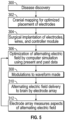
FIG. 5 is a flowchart showing the process of treatment and optimization for a patient using the system ofFIG. 1 ; - Corresponding reference characters indicate corresponding elements among the view of the drawings. The headings used in the figures do not limit the scope of the claims.
- The present invention provides a system for the treatment of brain cancer as defined in appended claims 1 to 15.
- Alternating electric field application is a burgeoning cancer treatment type with the potential to reduce treatment related toxicity. In alternating electric field application, an alternating electric field is applied to a cancerous region of the brain, thereby disrupting cellular division for rapidly-dividing cancer cells. To administer alternating electric field treatment to a patient, a system for generating an alternating electric field of optimized strength at a desired location within a body to inhibit cellular division and/or initiate apoptosis of cancer cells at the targeted treatment location is disclosed herein.
- The present system provides, among other aspects, a system of a subdural implant apparatus wherein, through the use of an array of subdural electrodes configured to be implanted subdurally and deep-stimulating electrodes configured to be implanted deep into the brain tissue, a targeted alternating electric field is generated for the treatment of rapidly dividing cancer cells. The array of stimulating electrodes is in operative communication with a controller module, wherein the controller module produces a waveform to create the alternating electric field and receives feedback from the array of stimulating electrodes. Referring to the drawings, embodiments of the present system are generally indicated as 100 in
FIGS. 1-5 . - Referring to
FIGS. 1 and2 , in some embodiments of thepresent system 100, amain array 101 includingstimulating electrodes main array 101 is in operative communication with acontroller module 120 by way of awire array 110. Thecontroller module 120 is operable to generate an alternating electric field, receive feedback from themain array 101, and communicate with anexternal computer 200 for receiving operating parameters as well as exporting operating data related to the strength of the alternating electric field. - The
main array 101 may include a plurality ofsubdural electrodes 103 as well as a plurality of deep-stimulating electrodes 104, such that thesubdural electrodes 103 and deep-stimulating electrodes 104 are operable to generate an alternating electric field that is applied to brain tissue. In one aspect, the alternating electric field is configured for appropriate strength and distribution such that cancerous cells in contact with the alternating electric field are prevented from dividing. In some embodiments, one or more wires 102, each defining a respective distal end, extend from a respectivesubdural electrode 103 and terminates in a conductive contact. In one possible application, each of the plurality ofsubdural electrodes 103 are placed on the surface of the brain. In some embodiments, thesubdural electrodes 103 may be thin enough to fit between the dura mater and the brain of the patient and may in some embodiments be surrounded by gel. Eachsubdural electrode 103 defines aproximal face 105 and a distal face (not shown), wherein the proximal face is in operative association with a distal end of each wire 102 and the distal face includes a transducing contact that is applied to the exterior of the brain. In some embodiments, the deep-stimulating electrodes 104 have elongated rod-shaped members comprising segmented strips of conductive material. The deep-stimulating electrodes 104 are implanted deep into the brain to facilitate penetration of the alternating electric field into the brain tissue. In some embodiments each of the deep-stimulating electrodes 104 defines a distal end and a proximal end, wherein the distal end of each of the deep-stimulating electrodes 104 is implanted into the brain tissue and the proximal end of each of the deep-stimulating electrodes 104 is in operative association with a respective wire 102. In some embodiments, the deep-stimulating electrodes 104 are operable to measure aspects of the alternating electric field applied to various locations within the brain by themain array 101 and communicate measured aspects of the alternating electric field back to thecontroller module 120. In one aspect, eachsubdural electrode 103 and deep-stimulating electrode 104 is operable to apply to tissue a current waveform through the wires 102. An alternating electric field is generated by the application of the waveform to the brain from multiple sources. - One visual example of the placement of
subdural electrodes 103 and deep-stimulating electrodes 104 relative to a cancerous region of the brain is shown inFIG. 3 . The optimal placement and number ofsubdural electrodes 103 and deep-stimulating electrodes 104 may vary between patients. Thus, a variety of imaging platforms may be used to scan the brain and determine optimal placement, types, and quantity ofelectrodes array 101. - Referring to
FIG. 4 , in some embodiments thecontroller module 120 includes awaveform generator 124 and aprocessing unit 122, wherein thewaveform generator 124 is in operative communication with thearray 101 by one ormore wires 110. Thewaveform generator 124 of thecontroller module 120 is operable to receive a set of operating parameters from theprocessing unit 122 and output a waveform such that when the waveform is distributed throughout thearray 101, an alternating electric field is applied to brain tissue. Theprocessing unit 122 of thecontroller module 120, such as a microprocessor or a microcontroller, is operable to output the set of operating parameters for thewaveform generator 124. Theprocessing unit 122 is also operable to receive input from thearray 101 pertaining to measured aspects of the alternating electric field and communicate the input to anexternal computer 200, update the set of operating parameters, and communicate the updated set of operating parameters to thewaveform generator 124. - Empirical research for TTF therapy recommends a 200 kHz standard waveform to be produced by the
waveform generator 124 to generate the alternating electric field. Ideal waveform modulation and intensity parameters are determined by theexternal computer 200 and delivered to thewaveform generator 124 through theprocessing unit 122. - The
controller module 120 may also include awireless communication module 126 that allows communication between theprocessing unit 122 of thecontroller module 120 andexternal computer 200. In this manner, theprocessing unit 122 of thecontroller module 120 is operable to wirelessly receive software updates and instructions from theexternal computer 200 as well as transmit the measured aspects of the alternating electric field to theexternal computer 200 for review and system optimization. Thecontroller module 120 may also include an implantable battery (not shown) or other power supply. - A non-claimed method for the treatment of cancer using the
system 100 is illustrated inFIG. 5 . Atstep 300 the disease is discovered and atstep 302, one or more cranial mapping techniques are employed to determine optimal placement and arrangement for theelectrode array 101. Atstep 304, theelectrode array 101,wires 110, andcontroller module 120 are surgically attached or implanted. Referring back toFIG. 2 , theelectrode array 101 is implanted in the cranium of a patient, wherein thesubdural electrodes 103 are placed subdurally on the surface of the brain and the deep-stimulatingelectrodes 104 are implanted deep into the brain. Thecontroller module 120 may be surgically implanted or installed subclavically or in the abdomen. In other cases, thecontroller module 120 may be installed outside the body, depending on the anatomy of the patient. - Referring back to
FIG. 5 , once theelectrode array 101, wires 102, andcontrol module 120 are attached or implanted, atstep 306 the alternating electric field generated by theelectrode array 101 is optimized using an initial set of parameters and the known location of eachsubdural electrode 103 and deep-stimulating electrode 104 on or within the patient's brain. The optimization process is performed using anexternal computer 200 that executes a simulation environment application to determine optimal waveform operating parameters for thecontroller module 120. The simulation environment application may be embodied as a program or an application and may be installed and operated on theexternal computer 200. When feedback information from thearray 101 is available, the feedback is incorporated into theoptimization step 306. Atstep 308, optimal waveform operating parameters are communicated to thecontroller module 120 and atstep 310 the optimized alternating electric field is then applied to the brain of the patient by thearray 101. As the alternating electric field is delivered, one or more of the deepstimulating electrodes 104 measure aspects of the alternating electric field and communicate this data to thecontroller module 120. Thecontroller module 120 records and/or transmits the information to theexternal computer 200 atstep 312. In this manner, the optimization process can be iteratively repeated using feedback pertaining to measured aspects of the alternating electric field and the exact location of eachsubdural electrode 103 and deep-stimulatingelectrode 104 until the alternating electric field is at its most effective application strength. - In some embodiments of the
system 100, the simulation environment used in the optimization process using theexternal computer 200 is operable to obtain the exact positions of thesubdural electrodes 103 and the deep-stimulatingelectrodes 104 as input as well as including information about the alternating electric field strength as measured by the deep-stimulatingelectrodes 104. In addition, the simulation environment application is operable to allow the user to observe changes in the alternating electric field delivered to the brain by changes in the waveform delivered to any givenelectrode electrodes electrodes electrodes 104 in the brain to ensure adequate alternating electric field strength is achieved. - It should be understood from the foregoing that, while particular embodiments have been illustrated and described, various modifications can be made thereto without departing from the scope of the invention as will be apparent to those skilled in the art. Such changes and modifications are within the scope and teachings of this invention as defined in the claims appended hereto.
Claims (15)
- A system (100) for the treatment of brain cancer, comprising:
an alternating electric field generation apparatus, comprising: an electrode array (101), comprising:a plurality of subdural electrodes (103), wherein each of the subdural electrodes (103) is configured to be implanted subdurally onto the brain of a patient;a plurality of deep-stimulating electrodes (104), wherein each of the plurality of deep-stimulating electrodes (104) is configured to be implanted;wherein the electrode array (101) delivers an alternating electric field to the tissue of the brain through the plurality of subdural electrodes (103) and the plurality of deep-stimulating electrodes (104); anda controller module (120) in operative communication with the electrode array (101), wherein the controller module (120) is operable to generate a waveform representative of the alternating electric field, wherein the waveform is transmitted to the electrode array (101); andan external computer (200), wherein the external computer (200) is operable to receive feedback from the controller module (120) and wherein the external computer (200) is operable to send commands to the controller module (120);wherein the controller module (120) is operable to incorporate feedback from the electrode array (101) and communicate the feedback to the external computer (200). - The system (100) of claim 1, wherein the controller module (120) comprises a wireless module, wherein the wireless module (126) is operable to communicate with the external computer (200) wirelessly.
- The system (100) of claim 2, wherein the controller module (120) further comprises a processing unit (122), wherein the processing unit (122) is operable to receive data pertaining to electric field strength from the electrode array (101), wherein the processing unit (122) is in operative communication with the wireless module (126).
- The system (100) of any preceding claim, further comprising:a plurality of conductive wires (102), wherein one or more of the plurality of conductive wires (102) are operable to transmit data pertaining to electric field strength from the electrode array (101) to the controller module (120), andwherein one or more of the plurality of conductive wires (102) are operable to transmit the waveform from the controller module (120) to the electrode array (101).
- The system (100) of any preceding claim, wherein the external computer (200) is operable to incorporate the feedback from the electrode array (101), a location of each of the plurality of subdural electrodes (103), and a location of each of the plurality of deep stimulating electrodes (104).
- The system (100) of any preceding claim, wherein the external computer (200) is operable to simulate effects of a set of parameters pertaining to the waveform on the brain, wherein the waveform is representative of the alternating electric field.
- The system (100) of any preceding claim, wherein the controller module (120) comprises:a waveform generator (124), wherein the waveform generator (124) is operable to generate a waveform representative of the alternating electric field, wherein the waveform is transmitted to the electrode array (101); anda processing unit (122), wherein the processing unit (122) is operable to communicate a set of waveform parameters to the waveform generator (124); andwherein the waveform generator (124) is operable to transmit a waveform to the electrode array (101) by one or more wires (102).
- The system (100) of claim 7, wherein the processing unit (122) is operable to receive a set of measured aspects of the alternating electric field from one or more of the plurality of deep-stimulating electrodes (104) of the electrode array (101).
- The system (100) of claim 8, wherein one or more of the plurality of conductive wires (102) are operable to transmit the set of measured aspects of the alternating electric field from the electrode array (101) to the controller module (120).
- The system (100) of any one of claims 7 to 9, comprising a plurality of conductive wires (102), wherein one or more of the plurality of conductive wires (102) are operable to transmit the waveform from the controller module (120) to the electrode array (101).
- The system (100) of any one of claims 7 to 10, wherein each of the plurality of deep stimulating electrodes (104) defines a rod-shaped member and wherein one or more conductive contacts are disposed along the rod-shaped member, wherein a proximal end of each of the plurality of deep stimulating members (104) is in operative association with one or more of the plurality of conductive wires (102).
- The system (100) of any one of claims 7 to 11, wherein each of the plurality or subdural electrodes (103) define opposing faces, wherein a distal face of the opposing faces comprises a conductive contact and wherein a proximal face of the opposing faces is in operative association with one or more conductive wires (102).
- The system (100) of any one of claims 8 to 12, wherein the external computer (200) is operable to optimize the alternating electric field generation apparatus using the measured aspects of the alternating electric field and the set of locations representative of each of the subdural electrodes (103) and each of the deep-stimulating electrodes (104), wherein a set of waveform parameters are transmitted to the controller module (120).
- The system (100) of claim 13, wherein the external computer (200) is operable to compute the set of waveform parameters for the alternating electric field generation apparatus using a simulation environment application, optionally wherein the controller module (120) is operable to send the measured aspects of the alternating electric field to the external computer (200), and wherein the external computer (200) is operable to send the set of waveform parameters to the controller module (120).
- The system (100) of claim 13 or claim 14, wherein the external computer (200) is operable to:determine an optimal placement configuration for each of the plurality of subdural electrodes (103) and each of the plurality of deep-stimulating electrodes (104) using cranial mapping software; and/orinitialize the alternating electric field generation system, wherein a set of initial waveform parameters are sent to the controller module (120), optionally wherein the simulation environment application predicts changes in the alternating electric field corresponding to a change in a waveform transmitted to the plurality of subdural electrodes or deep-stimulating electrodes, further optionally wherein the simulation environment application is operable to obtain a set of locations for each of the plurality of subdural electrodes (103) or deep-stimulating electrodes (104) and calculate a predicted distribution of the alternating electric field based on the waveform delivered to each of the plurality of subdural electrodes (103) or deep-stimulating electrodes (104), yet further optionally wherein the alternating electric field generation system is optimized by choosing the set of optimal waveform parameters which deliver an alternating electric field of appropriate distribution and strength to a cancerous region of the brain, wherein the set of optimal waveform parameters is representative of the waveform delivered to each of the plurality of subdural electrodes (103) or deep-stimulating electrodes (104).
Applications Claiming Priority (2)
| Application Number | Priority Date | Filing Date | Title |
|---|---|---|---|
| US201862699146P | 2018-07-17 | 2018-07-17 | |
| PCT/US2019/042197 WO2020018662A1 (en) | 2018-07-17 | 2019-07-17 | Systems and methods for treatment of cancer using alternating electric field generation |
Publications (3)
| Publication Number | Publication Date |
|---|---|
| EP3823714A1 EP3823714A1 (en) | 2021-05-26 |
| EP3823714A4 EP3823714A4 (en) | 2022-04-20 |
| EP3823714B1 true EP3823714B1 (en) | 2025-05-07 |
Family
ID=69164762
Family Applications (1)
| Application Number | Title | Priority Date | Filing Date |
|---|---|---|---|
| EP19837750.9A Active EP3823714B1 (en) | 2018-07-17 | 2019-07-17 | Systems for treatment of cancer using alternating electric field generation |
Country Status (7)
| Country | Link |
|---|---|
| US (3) | US11565111B2 (en) |
| EP (1) | EP3823714B1 (en) |
| JP (3) | JP7384895B2 (en) |
| CN (1) | CN112423836A (en) |
| AU (1) | AU2019306571B2 (en) |
| CA (1) | CA3104885A1 (en) |
| WO (1) | WO2020018662A1 (en) |
Families Citing this family (12)
| Publication number | Priority date | Publication date | Assignee | Title |
|---|---|---|---|---|
| US12403305B2 (en) | 2016-06-27 | 2025-09-02 | Galvanize Therapeutics, Inc. | Immunostimulation in the treatment of viral infection |
| CN109788979B (en) | 2016-06-27 | 2022-04-19 | 盖能适治疗股份有限公司 | Generator and catheter with electrodes and method for treating a lung passageway |
| CN118383863A (en) | 2017-12-26 | 2024-07-26 | 盖能适治疗股份有限公司 | Optimization of energy delivery for various applications |
| JP7384895B2 (en) | 2018-07-17 | 2023-11-21 | ディグニティー ヘルス | Systems and methods for cancer treatment using alternating current electric field generation |
| AU2020257266A1 (en) | 2019-04-18 | 2021-11-11 | Galvanize Therapeutics, Inc. | Devices, systems and methods for the treatment of abnormal tissue |
| WO2021011733A1 (en) | 2019-07-16 | 2021-01-21 | Galary, Inc. | Treatment of the reproductive tract with pulsed electric fields |
| GB2604400A (en) | 2021-03-05 | 2022-09-07 | Qv Bioelectronics Ltd | Biphasic injectable electrode |
| GB2604397A (en) | 2021-03-05 | 2022-09-07 | Qv Bioelectronics Ltd | Cranial Prosthetic |
| WO2023168034A1 (en) * | 2022-03-03 | 2023-09-07 | Medtronic, Inc. | Electrode configurations for electric field therapy |
| JP2025522725A (en) * | 2022-06-27 | 2025-07-17 | ノボキュア ゲーエムベーハー | Using closed-loop technology to simultaneously treat subjects with alternating electric fields and reduce electrical sensations |
| WO2024062456A1 (en) * | 2022-09-23 | 2024-03-28 | Novocure Gmbh | 3d models for predicting treatment responses to alternating electric fields |
| CN119455251A (en) * | 2024-11-05 | 2025-02-18 | 海南派云科技有限公司 | A multi-mode-based electric field regulation system for tumor therapy |
Family Cites Families (19)
| Publication number | Priority date | Publication date | Assignee | Title |
|---|---|---|---|---|
| US6340353B1 (en) * | 1996-09-30 | 2002-01-22 | Jeanne K. Pomatto | Manufacture of cranial remodeling orthosis |
| US20050021118A1 (en) * | 2000-07-13 | 2005-01-27 | Chris Genau | Apparatuses and systems for applying electrical stimulation to a patient |
| WO2004037341A2 (en) * | 2002-05-07 | 2004-05-06 | Schroeppel Edward A | Method and device for treating concer with electrical therapy in conjunction with chemotherapeutic agents and radiation therapy |
| US7826902B2 (en) * | 2006-02-24 | 2010-11-02 | Medtronic, Inc. | User interface with 2D views for configuring stimulation therapy |
| US20080046023A1 (en) * | 2006-08-16 | 2008-02-21 | Fischell David R | Electrode switch for a brain neuropacemaker |
| US8364284B2 (en) * | 2008-09-15 | 2013-01-29 | Boston Scientific Neuromodulation Corporation | Implantable electric stimulation system and methods of making and using |
| GB0821325D0 (en) * | 2008-11-21 | 2008-12-31 | Ucl Business Plc | Method and apparatus for performing deep brain stimulation with an electric field |
| JP2012521863A (en) * | 2009-03-31 | 2012-09-20 | アンジオダイナミツクス・インコーポレイテツド | System and method for treatment area estimation and interactive patient treatment planning of treatment devices |
| EP2419171B1 (en) * | 2009-04-13 | 2017-11-01 | Research Foundation Of The City University Of New York | Neurocranial electrostimulation models |
| BRPI1015422A2 (en) * | 2009-07-30 | 2016-04-19 | Sapiens Steering Brain Stimulation Bv | deep brain stimulation system, methods for determining amplitudes, for applying a spatial distribution of amplitudes and computer program product. |
| US8996115B2 (en) * | 2011-04-07 | 2015-03-31 | Greatbatch, Ltd. | Charge balancing for arbitrary waveform generator and neural stimulation application |
| DE112014003405A5 (en) * | 2013-07-23 | 2016-05-19 | Florian König Enterprises Gmbh | Replication and extension of near-natural Sferics signal sequences as electromagnetic alternating field |
| CN107921257A (en) * | 2015-05-14 | 2018-04-17 | 伦敦健康科学中心研究有限公司 | Therapy is adjusted in knurl |
| JP7071257B2 (en) * | 2015-05-31 | 2022-05-18 | クローズド・ループ・メディカル・ピーティーワイ・リミテッド | Installation of cranial nerve stimulator electrodes |
| US10525267B2 (en) * | 2015-06-02 | 2020-01-07 | Battelle Memorial Institute | Closed loop deep brain stimulation systems and methods |
| US10188851B2 (en) * | 2015-10-28 | 2019-01-29 | Novocure Limited | TTField treatment with optimization of electrode positions on the head based on MRI-based conductivity measurements |
| WO2018057953A2 (en) | 2016-09-23 | 2018-03-29 | Beth Isreal Deaconess Medical Center, Inc. | System and methods for cancer treatment using alternating electric fields |
| CN106823140B (en) * | 2017-01-14 | 2023-03-03 | 北京品驰医疗设备有限公司 | Sacral nerve stimulator capable of adjusting electric field direction |
| JP7384895B2 (en) | 2018-07-17 | 2023-11-21 | ディグニティー ヘルス | Systems and methods for cancer treatment using alternating current electric field generation |
-
2019
- 2019-07-17 JP JP2021501284A patent/JP7384895B2/en active Active
- 2019-07-17 AU AU2019306571A patent/AU2019306571B2/en active Active
- 2019-07-17 EP EP19837750.9A patent/EP3823714B1/en active Active
- 2019-07-17 CA CA3104885A patent/CA3104885A1/en active Pending
- 2019-07-17 US US17/260,019 patent/US11565111B2/en active Active
- 2019-07-17 CN CN201980047095.3A patent/CN112423836A/en active Pending
- 2019-07-17 WO PCT/US2019/042197 patent/WO2020018662A1/en not_active Ceased
-
2023
- 2023-01-18 US US18/155,849 patent/US12214196B2/en active Active
- 2023-11-09 JP JP2023191834A patent/JP7807153B2/en active Active
-
2025
- 2025-01-08 US US19/013,920 patent/US20250144424A1/en active Pending
-
2026
- 2026-01-09 JP JP2026002726A patent/JP2026042984A/en active Pending
Also Published As
| Publication number | Publication date |
|---|---|
| AU2019306571B2 (en) | 2024-06-20 |
| US20210308455A1 (en) | 2021-10-07 |
| US11565111B2 (en) | 2023-01-31 |
| JP2023184733A (en) | 2023-12-28 |
| AU2019306571A1 (en) | 2021-01-21 |
| CA3104885A1 (en) | 2020-01-23 |
| JP2026042984A (en) | 2026-03-11 |
| US20230149713A1 (en) | 2023-05-18 |
| JP7384895B2 (en) | 2023-11-21 |
| EP3823714A4 (en) | 2022-04-20 |
| US20250144424A1 (en) | 2025-05-08 |
| JP7807153B2 (en) | 2026-01-27 |
| WO2020018662A1 (en) | 2020-01-23 |
| EP3823714A1 (en) | 2021-05-26 |
| CN112423836A (en) | 2021-02-26 |
| US12214196B2 (en) | 2025-02-04 |
| JP2021531090A (en) | 2021-11-18 |
Similar Documents
| Publication | Publication Date | Title |
|---|---|---|
| US12214196B2 (en) | Systems and methods for treatment of cancer using alternating electric field generation | |
| CN114025833B (en) | Methods and systems for electrical stimulation adjustment based on patient-specific factors | |
| JP5996545B2 (en) | System and method for introducing a tissue stimulation lead into a patient using real-time coupling efficiency measurement | |
| US10960214B2 (en) | Systems and methods for controlling electrical stimulation using multiple stimulation fields | |
| CN106714678B (en) | Apparatus and method for pain management using power spectrum or signal correlation | |
| US11389655B2 (en) | Adaptive chronic pain relief via implanted electrical neurostimulation | |
| US20220212014A1 (en) | Method and apparatus for determining tolerance thresholds for neurostimulation | |
| US12447337B2 (en) | Systems and methods for determining neuromodulation parameters | |
| US20170281949A1 (en) | Distributed electrode lead configurations and associated systems and methods | |
| WO2023168033A1 (en) | Electric field therapy via implantable electrodes | |
| Guillen et al. | The interplay between pulse width and activation depth in TENS: a computational study | |
| US20240261585A1 (en) | Method and system for optimizing electrode array structure in electrotherapy | |
| US20250360318A1 (en) | Method and apparatus for neurostimulation with discrete dynamic patterns | |
| US20250249257A1 (en) | Method and apparatus for ecap-based dynamic stimulation programming | |
| US20240100338A1 (en) | System and method for treating chronic pain | |
| CN119909316A (en) | Transcranial electrical stimulation system and method for reducing skin reactions |
Legal Events
| Date | Code | Title | Description |
|---|---|---|---|
| STAA | Information on the status of an ep patent application or granted ep patent |
Free format text: STATUS: THE INTERNATIONAL PUBLICATION HAS BEEN MADE |
|
| PUAI | Public reference made under article 153(3) epc to a published international application that has entered the european phase |
Free format text: ORIGINAL CODE: 0009012 |
|
| STAA | Information on the status of an ep patent application or granted ep patent |
Free format text: STATUS: REQUEST FOR EXAMINATION WAS MADE |
|
| 17P | Request for examination filed |
Effective date: 20210215 |
|
| AK | Designated contracting states |
Kind code of ref document: A1 Designated state(s): AL AT BE BG CH CY CZ DE DK EE ES FI FR GB GR HR HU IE IS IT LI LT LU LV MC MK MT NL NO PL PT RO RS SE SI SK SM TR |
|
| DAV | Request for validation of the european patent (deleted) | ||
| DAX | Request for extension of the european patent (deleted) | ||
| A4 | Supplementary search report drawn up and despatched |
Effective date: 20220318 |
|
| RIC1 | Information provided on ipc code assigned before grant |
Ipc: A61N 1/375 20060101ALN20220314BHEP Ipc: A61N 1/372 20060101ALN20220314BHEP Ipc: A61N 1/40 20060101ALI20220314BHEP Ipc: A61N 1/36 20060101ALI20220314BHEP Ipc: A61N 1/05 20060101AFI20220314BHEP |
|
| GRAP | Despatch of communication of intention to grant a patent |
Free format text: ORIGINAL CODE: EPIDOSNIGR1 |
|
| STAA | Information on the status of an ep patent application or granted ep patent |
Free format text: STATUS: GRANT OF PATENT IS INTENDED |
|
| RIC1 | Information provided on ipc code assigned before grant |
Ipc: A61N 1/375 20060101ALN20241126BHEP Ipc: A61N 1/372 20060101ALN20241126BHEP Ipc: A61N 1/40 20060101ALI20241126BHEP Ipc: A61N 1/36 20060101ALI20241126BHEP Ipc: A61N 1/05 20060101AFI20241126BHEP |
|
| INTG | Intention to grant announced |
Effective date: 20241204 |
|
| GRAS | Grant fee paid |
Free format text: ORIGINAL CODE: EPIDOSNIGR3 |
|
| GRAA | (expected) grant |
Free format text: ORIGINAL CODE: 0009210 |
|
| STAA | Information on the status of an ep patent application or granted ep patent |
Free format text: STATUS: THE PATENT HAS BEEN GRANTED |
|
| P01 | Opt-out of the competence of the unified patent court (upc) registered |
Free format text: CASE NUMBER: APP_12858/2025 Effective date: 20250314 |
|
| AK | Designated contracting states |
Kind code of ref document: B1 Designated state(s): AL AT BE BG CH CY CZ DE DK EE ES FI FR GB GR HR HU IE IS IT LI LT LU LV MC MK MT NL NO PL PT RO RS SE SI SK SM TR |
|
| REG | Reference to a national code |
Ref country code: GB Ref legal event code: FG4D |
|
| REG | Reference to a national code |
Ref country code: CH Ref legal event code: EP |
|
| REG | Reference to a national code |
Ref country code: DE Ref legal event code: R096 Ref document number: 602019069741 Country of ref document: DE |
|
| REG | Reference to a national code |
Ref country code: IE Ref legal event code: FG4D |
|
| REG | Reference to a national code |
Ref country code: NL Ref legal event code: MP Effective date: 20250507 |
|
| PG25 | Lapsed in a contracting state [announced via postgrant information from national office to epo] |
Ref country code: PT Free format text: LAPSE BECAUSE OF FAILURE TO SUBMIT A TRANSLATION OF THE DESCRIPTION OR TO PAY THE FEE WITHIN THE PRESCRIBED TIME-LIMIT Effective date: 20250908 Ref country code: ES Free format text: LAPSE BECAUSE OF FAILURE TO SUBMIT A TRANSLATION OF THE DESCRIPTION OR TO PAY THE FEE WITHIN THE PRESCRIBED TIME-LIMIT Effective date: 20250507 Ref country code: FI Free format text: LAPSE BECAUSE OF FAILURE TO SUBMIT A TRANSLATION OF THE DESCRIPTION OR TO PAY THE FEE WITHIN THE PRESCRIBED TIME-LIMIT Effective date: 20250507 |
|
| PGFP | Annual fee paid to national office [announced via postgrant information from national office to epo] |
Ref country code: DE Payment date: 20250722 Year of fee payment: 7 |
|
| REG | Reference to a national code |
Ref country code: LT Ref legal event code: MG9D |
|
| PG25 | Lapsed in a contracting state [announced via postgrant information from national office to epo] |
Ref country code: GR Free format text: LAPSE BECAUSE OF FAILURE TO SUBMIT A TRANSLATION OF THE DESCRIPTION OR TO PAY THE FEE WITHIN THE PRESCRIBED TIME-LIMIT Effective date: 20250808 Ref country code: NO Free format text: LAPSE BECAUSE OF FAILURE TO SUBMIT A TRANSLATION OF THE DESCRIPTION OR TO PAY THE FEE WITHIN THE PRESCRIBED TIME-LIMIT Effective date: 20250807 |
|
| PG25 | Lapsed in a contracting state [announced via postgrant information from national office to epo] |
Ref country code: NL Free format text: LAPSE BECAUSE OF FAILURE TO SUBMIT A TRANSLATION OF THE DESCRIPTION OR TO PAY THE FEE WITHIN THE PRESCRIBED TIME-LIMIT Effective date: 20250507 Ref country code: PL Free format text: LAPSE BECAUSE OF FAILURE TO SUBMIT A TRANSLATION OF THE DESCRIPTION OR TO PAY THE FEE WITHIN THE PRESCRIBED TIME-LIMIT Effective date: 20250507 |
|
| REG | Reference to a national code |
Ref country code: AT Ref legal event code: MK05 Ref document number: 1791829 Country of ref document: AT Kind code of ref document: T Effective date: 20250507 |
|
| PG25 | Lapsed in a contracting state [announced via postgrant information from national office to epo] |
Ref country code: BG Free format text: LAPSE BECAUSE OF FAILURE TO SUBMIT A TRANSLATION OF THE DESCRIPTION OR TO PAY THE FEE WITHIN THE PRESCRIBED TIME-LIMIT Effective date: 20250507 |
|
| PGFP | Annual fee paid to national office [announced via postgrant information from national office to epo] |
Ref country code: GB Payment date: 20250722 Year of fee payment: 7 |
|
| PG25 | Lapsed in a contracting state [announced via postgrant information from national office to epo] |
Ref country code: HR Free format text: LAPSE BECAUSE OF FAILURE TO SUBMIT A TRANSLATION OF THE DESCRIPTION OR TO PAY THE FEE WITHIN THE PRESCRIBED TIME-LIMIT Effective date: 20250507 |
|
| PG25 | Lapsed in a contracting state [announced via postgrant information from national office to epo] |
Ref country code: AT Free format text: LAPSE BECAUSE OF FAILURE TO SUBMIT A TRANSLATION OF THE DESCRIPTION OR TO PAY THE FEE WITHIN THE PRESCRIBED TIME-LIMIT Effective date: 20250507 |
|
| PGFP | Annual fee paid to national office [announced via postgrant information from national office to epo] |
Ref country code: FR Payment date: 20250725 Year of fee payment: 7 |
|
| PG25 | Lapsed in a contracting state [announced via postgrant information from national office to epo] |
Ref country code: RS Free format text: LAPSE BECAUSE OF FAILURE TO SUBMIT A TRANSLATION OF THE DESCRIPTION OR TO PAY THE FEE WITHIN THE PRESCRIBED TIME-LIMIT Effective date: 20250807 |
|
| PG25 | Lapsed in a contracting state [announced via postgrant information from national office to epo] |
Ref country code: IS Free format text: LAPSE BECAUSE OF FAILURE TO SUBMIT A TRANSLATION OF THE DESCRIPTION OR TO PAY THE FEE WITHIN THE PRESCRIBED TIME-LIMIT Effective date: 20250907 |
|
| PG25 | Lapsed in a contracting state [announced via postgrant information from national office to epo] |
Ref country code: LV Free format text: LAPSE BECAUSE OF FAILURE TO SUBMIT A TRANSLATION OF THE DESCRIPTION OR TO PAY THE FEE WITHIN THE PRESCRIBED TIME-LIMIT Effective date: 20250507 |
|
| PG25 | Lapsed in a contracting state [announced via postgrant information from national office to epo] |
Ref country code: DK Free format text: LAPSE BECAUSE OF FAILURE TO SUBMIT A TRANSLATION OF THE DESCRIPTION OR TO PAY THE FEE WITHIN THE PRESCRIBED TIME-LIMIT Effective date: 20250507 Ref country code: SM Free format text: LAPSE BECAUSE OF FAILURE TO SUBMIT A TRANSLATION OF THE DESCRIPTION OR TO PAY THE FEE WITHIN THE PRESCRIBED TIME-LIMIT Effective date: 20250507 |
|
| PG25 | Lapsed in a contracting state [announced via postgrant information from national office to epo] |
Ref country code: CZ Free format text: LAPSE BECAUSE OF FAILURE TO SUBMIT A TRANSLATION OF THE DESCRIPTION OR TO PAY THE FEE WITHIN THE PRESCRIBED TIME-LIMIT Effective date: 20250507 |
|
| PG25 | Lapsed in a contracting state [announced via postgrant information from national office to epo] |
Ref country code: EE Free format text: LAPSE BECAUSE OF FAILURE TO SUBMIT A TRANSLATION OF THE DESCRIPTION OR TO PAY THE FEE WITHIN THE PRESCRIBED TIME-LIMIT Effective date: 20250507 |
|
| PG25 | Lapsed in a contracting state [announced via postgrant information from national office to epo] |
Ref country code: SK Free format text: LAPSE BECAUSE OF FAILURE TO SUBMIT A TRANSLATION OF THE DESCRIPTION OR TO PAY THE FEE WITHIN THE PRESCRIBED TIME-LIMIT Effective date: 20250507 Ref country code: RO Free format text: LAPSE BECAUSE OF FAILURE TO SUBMIT A TRANSLATION OF THE DESCRIPTION OR TO PAY THE FEE WITHIN THE PRESCRIBED TIME-LIMIT Effective date: 20250507 |
|
| PG25 | Lapsed in a contracting state [announced via postgrant information from national office to epo] |
Ref country code: IT Free format text: LAPSE BECAUSE OF FAILURE TO SUBMIT A TRANSLATION OF THE DESCRIPTION OR TO PAY THE FEE WITHIN THE PRESCRIBED TIME-LIMIT Effective date: 20250507 |
|
| REG | Reference to a national code |
Ref country code: DE Ref legal event code: R097 Ref document number: 602019069741 Country of ref document: DE |
|
| REG | Reference to a national code |
Ref country code: CH Ref legal event code: H13 Free format text: ST27 STATUS EVENT CODE: U-0-0-H10-H13 (AS PROVIDED BY THE NATIONAL OFFICE) Effective date: 20260224 |
|
| PLBE | No opposition filed within time limit |
Free format text: ORIGINAL CODE: 0009261 |
|
| STAA | Information on the status of an ep patent application or granted ep patent |
Free format text: STATUS: NO OPPOSITION FILED WITHIN TIME LIMIT |
|
| PG25 | Lapsed in a contracting state [announced via postgrant information from national office to epo] |
Ref country code: LU Free format text: LAPSE BECAUSE OF NON-PAYMENT OF DUE FEES Effective date: 20250717 |
|
| REG | Reference to a national code |
Ref country code: CH Ref legal event code: L10 Free format text: ST27 STATUS EVENT CODE: U-0-0-L10-L00 (AS PROVIDED BY THE NATIONAL OFFICE) Effective date: 20260318 |
|
| REG | Reference to a national code |
Ref country code: BE Ref legal event code: MM Effective date: 20250731 |
|
| 26N | No opposition filed |
Effective date: 20260210 |
|
| PG25 | Lapsed in a contracting state [announced via postgrant information from national office to epo] |
Ref country code: BE Free format text: LAPSE BECAUSE OF NON-PAYMENT OF DUE FEES Effective date: 20250731 |
|
| PG25 | Lapsed in a contracting state [announced via postgrant information from national office to epo] |
Ref country code: CH Free format text: LAPSE BECAUSE OF NON-PAYMENT OF DUE FEES Effective date: 20250731 |