EP3823580B1 - Semi-rigid and flexible elements for wearable drug delivery device reservoir - Google Patents
Semi-rigid and flexible elements for wearable drug delivery device reservoir Download PDFInfo
- Publication number
- EP3823580B1 EP3823580B1 EP19746416.7A EP19746416A EP3823580B1 EP 3823580 B1 EP3823580 B1 EP 3823580B1 EP 19746416 A EP19746416 A EP 19746416A EP 3823580 B1 EP3823580 B1 EP 3823580B1
- Authority
- EP
- European Patent Office
- Prior art keywords
- reservoir
- flexible
- drug
- component
- rigid
- Prior art date
- Legal status (The legal status is an assumption and is not a legal conclusion. Google has not performed a legal analysis and makes no representation as to the accuracy of the status listed.)
- Active
Links
Images





Classifications
-
- A—HUMAN NECESSITIES
- A61—MEDICAL OR VETERINARY SCIENCE; HYGIENE
- A61M—DEVICES FOR INTRODUCING MEDIA INTO, OR ONTO, THE BODY; DEVICES FOR TRANSDUCING BODY MEDIA OR FOR TAKING MEDIA FROM THE BODY; DEVICES FOR PRODUCING OR ENDING SLEEP OR STUPOR
- A61M5/00—Devices for bringing media into the body in a subcutaneous, intra-vascular or intramuscular way; Accessories therefor, e.g. filling or cleaning devices, arm rests
- A61M5/14—Infusion devices, e.g. infusing by gravity; Blood infusion; Accessories therefor
- A61M5/142—Pressure infusion, e.g. using pumps
- A61M5/145—Pressure infusion, e.g. using pumps using pressurised reservoirs, e.g. by means of pistons
- A61M5/148—Pressure infusion, e.g. using pumps using pressurised reservoirs, e.g. by means of pistons flexible
-
- A—HUMAN NECESSITIES
- A61—MEDICAL OR VETERINARY SCIENCE; HYGIENE
- A61J—CONTAINERS SPECIALLY ADAPTED FOR MEDICAL OR PHARMACEUTICAL PURPOSES; DEVICES OR METHODS SPECIALLY ADAPTED FOR BRINGING PHARMACEUTICAL PRODUCTS INTO PARTICULAR PHYSICAL OR ADMINISTERING FORMS; DEVICES FOR ADMINISTERING FOOD OR MEDICINES ORALLY; BABY COMFORTERS; DEVICES FOR RECEIVING SPITTLE
- A61J1/00—Containers specially adapted for medical or pharmaceutical purposes
- A61J1/05—Containers specially adapted for medical or pharmaceutical purposes for collecting, storing or administering blood, plasma or medical fluids ; Infusion or perfusion containers
-
- A—HUMAN NECESSITIES
- A61—MEDICAL OR VETERINARY SCIENCE; HYGIENE
- A61J—CONTAINERS SPECIALLY ADAPTED FOR MEDICAL OR PHARMACEUTICAL PURPOSES; DEVICES OR METHODS SPECIALLY ADAPTED FOR BRINGING PHARMACEUTICAL PRODUCTS INTO PARTICULAR PHYSICAL OR ADMINISTERING FORMS; DEVICES FOR ADMINISTERING FOOD OR MEDICINES ORALLY; BABY COMFORTERS; DEVICES FOR RECEIVING SPITTLE
- A61J1/00—Containers specially adapted for medical or pharmaceutical purposes
- A61J1/14—Details; Accessories therefor
- A61J1/20—Arrangements for transferring or mixing fluids, e.g. from vial to syringe
- A61J1/2003—Accessories used in combination with means for transfer or mixing of fluids, e.g. for activating fluid flow, separating fluids, filtering fluid or venting
- A61J1/202—Separating means
- A61J1/2024—Separating means having peelable seals
-
- A—HUMAN NECESSITIES
- A61—MEDICAL OR VETERINARY SCIENCE; HYGIENE
- A61M—DEVICES FOR INTRODUCING MEDIA INTO, OR ONTO, THE BODY; DEVICES FOR TRANSDUCING BODY MEDIA OR FOR TAKING MEDIA FROM THE BODY; DEVICES FOR PRODUCING OR ENDING SLEEP OR STUPOR
- A61M5/00—Devices for bringing media into the body in a subcutaneous, intra-vascular or intramuscular way; Accessories therefor, e.g. filling or cleaning devices, arm rests
- A61M5/14—Infusion devices, e.g. infusing by gravity; Blood infusion; Accessories therefor
- A61M5/142—Pressure infusion, e.g. using pumps
- A61M5/14244—Pressure infusion, e.g. using pumps adapted to be carried by the patient, e.g. portable on the body
- A61M5/14248—Pressure infusion, e.g. using pumps adapted to be carried by the patient, e.g. portable on the body of the skin patch type
-
- A—HUMAN NECESSITIES
- A61—MEDICAL OR VETERINARY SCIENCE; HYGIENE
- A61M—DEVICES FOR INTRODUCING MEDIA INTO, OR ONTO, THE BODY; DEVICES FOR TRANSDUCING BODY MEDIA OR FOR TAKING MEDIA FROM THE BODY; DEVICES FOR PRODUCING OR ENDING SLEEP OR STUPOR
- A61M2205/00—General characteristics of the apparatus
- A61M2205/33—Controlling, regulating or measuring
- A61M2205/3331—Pressure; Flow
- A61M2205/3334—Measuring or controlling the flow rate
-
- A—HUMAN NECESSITIES
- A61—MEDICAL OR VETERINARY SCIENCE; HYGIENE
- A61M—DEVICES FOR INTRODUCING MEDIA INTO, OR ONTO, THE BODY; DEVICES FOR TRANSDUCING BODY MEDIA OR FOR TAKING MEDIA FROM THE BODY; DEVICES FOR PRODUCING OR ENDING SLEEP OR STUPOR
- A61M2205/00—General characteristics of the apparatus
- A61M2205/33—Controlling, regulating or measuring
- A61M2205/3379—Masses, volumes, levels of fluids in reservoirs, flow rates
-
- A—HUMAN NECESSITIES
- A61—MEDICAL OR VETERINARY SCIENCE; HYGIENE
- A61M—DEVICES FOR INTRODUCING MEDIA INTO, OR ONTO, THE BODY; DEVICES FOR TRANSDUCING BODY MEDIA OR FOR TAKING MEDIA FROM THE BODY; DEVICES FOR PRODUCING OR ENDING SLEEP OR STUPOR
- A61M5/00—Devices for bringing media into the body in a subcutaneous, intra-vascular or intramuscular way; Accessories therefor, e.g. filling or cleaning devices, arm rests
- A61M5/14—Infusion devices, e.g. infusing by gravity; Blood infusion; Accessories therefor
- A61M5/142—Pressure infusion, e.g. using pumps
- A61M5/145—Pressure infusion, e.g. using pumps using pressurised reservoirs, e.g. by means of pistons
- A61M5/14586—Pressure infusion, e.g. using pumps using pressurised reservoirs, e.g. by means of pistons pressurised by means of a flexible diaphragm
Definitions
- the present application generally relates to medication delivery devices, and more particularly to reservoirs or reservoirs for storing a liquid drug within a drug delivery device.
- a fully rigid reservoir or a fully flexible reservoir for storing a liquid drug.
- Each type of reservoir includes one or more advantages and disadvantages over the other type of reservoir.
- Fully rigid reservoirs take up space that may be better used. While fully flexible reservoirs may be space efficient and may require relatively lower pumping pressures, the flexible reservoirs present challenges compared to fully rigid reservoirs. For example, the expansion and collapse of earlier flexible reservoirs may be unpredictable, thereby leading to undesirable hold up volumes and difficulties in determining stored fluid volumes (e.g., inaccurate fill gauging).
- Flexible reservoirs also present challenges related to vapor transmissivity. In some instances, a small volume of fluid is spread across a large surface area on a thin flexible membrane.
- WO 2012/065780 A2 discloses a reservoir for storing a liquid drug, the reservoir comprising a shell component and a flexible component coupled thereto.
- a similar reservoir is known from EP 2 556 815 A1 , which represents prior art under Article 54(3) EPC. In both cases, the flexible component does not deflate and conform to the inner surface of the shell component.
- the invention comprises a reservoir for storing a liquid drug as defined in claim 1. Additional features of preferred embodiments are defined in the dependent claims. Disclosed is an example of a reservoir for storing a liquid drug.
- the reservoir includes a shell component, a flexible component and a port.
- the flexible component is coupled to the shell component.
- the coupling is a hermetic seal.
- the port is configured to enable filling of emptying of the reservoir.
- An example of a reservoir system includes a flexible reservoir and an exoskeleton.
- the flexible reservoir is configured to expand when filled with a liquid drug.
- the exoskeleton is coupled to the flexible reservoir.
- a system example in which the system include a reservoir, one or more peel-able restraints positioned on the flexible reservoir.
- the one or more peel-able restraints are configured to seal off one or more corresponding sections of the flexible reservoir, and sequentially break to allow a liquid to fill a next corresponding section of the one or more corresponding sections of the flexible reservoir as the flexible reservoir is filled with the liquid.
- a need therefore exists for a drug delivery device that includes a drug reservoir or reservoir that combines the advantages of fully flexible and fully rigid reservoirs while mitigating one or more disadvantages of fully flexible and fully rigid reservoirs.
- a flexible reservoir system that may expand and collapse in a more predictable manner, to reduce hold up volumes and enable accurate stored fluid volume determinations, while retaining the advantages of flexible reservoirs such as high space efficiency or low pumping pressure.
- FIG. 1 illustrates a cross-sectional side view of a first example of a drug reservoir in a filled state and an unfilled state.
- the combination of components for forming the reservoir may, for example, allow the liquid drug to be stored and then expelled from the reservoir with relatively lower pumping pressures (as compared to fully rigid drug reservoirs) and without the need for a plunger as well as other apparent advantages.
- the drug reservoir 100 includes a shell component 102 that may be rigid or semi-rigid and a flexible component 104.
- the shell component 102 may be formed from a variety of materials including, for example, plastic or metal, or any combination thereof.
- the flexible component 104 may be formed from a variety of flexible materials including, for example, a flexible plastic film.
- the flexible component 104 has greater flexibility than the shell component 102.
- FIG. 1 shows the drug reservoir 100 in an unfilled state and in a filled state. When filled, the flexible component 104 expands in response to a liquid drug (not shown) filling the drug reservoir 100 from a port (shown in other examples).
- the expansion of the flexible component 104 and the hermetic coupling or seal to the shell component 102 enables the drug reservoir 100 to contain a liquid drug (or other fluid or therapeutic agent) 106.
- the shell component 102 is an open shell.
- the shell component 102 may be integrated into other parts, such as a housing or chassis thereby enabling a rigid or semi-rigid shell component 102 to serve multiple purposes, such as part of a housing for the wearable drug delivery device, a structure element of another part (e.g. a battery clip or retainer) of the wearable drug delivery device, or the like.
- the flexible component 104 may be coupled to the shell component 102 in a number of manners including, for example, mechanically, through use of an adhesive, or through use of an adhesive tape or the like.
- the coupling of the flexible component 104 to the shell component 102 is a hermetic seal thereby forming the reservoir 100 that is able to contain the liquid drug or other fluid.
- the shell component 102 may be of any size or shape. As shown in FIG. 1 , the shell component 102 may form a bowl with an upper ridge or lip to support and provide coupling to the flexible component 104.
- FIG. 2 illustrates a top view and a corresponding side view of a second example of a drug reservoir.
- the drug reservoir 200 may be a particular implementation of the drug reservoir 100.
- the drug reservoir 200 may include a rigid or semi-rigid shell component 202 and a flexible component 204.
- the flexible component 204 may be formed from a thin flexible film, or the like.
- the shell component 202 may be an open shell.
- the flexible component 204 may be sealed (i.e., coupled to form hermetic seal) to the shell component 202 - for example, along a perimeter of the shell component 202.
- an adhesive such as ultrasonic welding or the like, may be used to couple or affix the flexible film component to the shell component 202.
- the sealing of the flexible component 204 to the shell component 202 is hermetic thereby forming the reservoir 200 that contains the liquid drug or other fluid.
- the side view shows the flexible component 204 in a deflated state 204-1 and in an inflated or expanded state 204-2 when filled with a fluid. When inflated or expanded, the flexible component 204 may provide a chamber 208 for storing a fluid.
- the drug reservoir 200 may further include an opening or side port 206.
- the side port 206 may be coupled to a fluid extraction component such as, for example, a pump (not shown).
- the side port 206 may also be coupled to a fluid path (not shown) coupled to a patient or user of a wearable drug device containing the drug reservoir 200.
- the side port 206 may be formed as a portion of the shell component 202 or may be a separate component coupled to the drug reservoir 200.
- a liquid drug or other fluid may enter and/or exit the drug reservoir 200 from the side port 206.
- the drug reservoir 200 may further include one or more recessed drainage channels 210.
- the drainage channels 210 may be formed into the shell component 202, for example, into an inner surface of the shell component 202.
- the drainage channels 210 instead of being formed in the shell component 202, may be formed into the flexible component 204, for example, into an inner surface (i.e., inside the drug reservoir 200 at a surface that contacts the liquid) of the flexible component 204.
- the drainage channels 210 may be formed in the shell component 202 and the flexible component 204, for example, in an inner surface of each of the shell component 202 and the flexible component 204.
- the drainage channels 210 may improve drainage of the drug reservoir 200, particularly as the drug reservoir 200 is nearly emptied of a stored liquid drug.
- the channels may be a similar depth along the entire length of the channel or may have a graded depth to facilitate flow toward a port.
- the interior of the reservoir on the film 204, the shell 202 or both may have a textured surface, such as stippling (e.g., bumps), ridges, grooves, or the like, configured to minimize the surface area upon which surfaces of film 204 and shell 202 at the interior of the reservoir 200 may contact one another as the fluid evacuates the reservoir.
- FIG. 3 illustrates a top view and a corresponding side view of a third example of a drug reservoir according to the disclosure.
- the drug reservoir 300 may include a rigid or semi-rigid shell component 302 and a flexible film component 304.
- the flexible film component 304 may be sealed or coupled to the shell component 302 - for example, along a perimeter of the shell component 302, to form a hermetic seal between the flexible film component 304 and the shell component 302.
- the corresponding side view of drug reservoir 300 shows the flexible film component 304 in a deflated state 304-1 and in an inflated or expanded state 304-2. When inflated or expanded, the flexible film component 304 may provide a chamber 308 for storing a fluid.
- the drug reservoir 300 may further include an opening or central face port 306.
- the central face port 306 may be coupled to a fluid extraction component such as, for example, a pump.
- the central face port 306 may also be coupled to a fluid path coupled to a patient or user of a wearable drug device containing the drug reservoir 300.
- the central face port 306 may include a pierceable septum accessible from a bottom side of the drug reservoir 300.
- the central face port 306 may be formed as part of the shell component 302 or may be a separate component coupled to the drug reservoir 300. A liquid drug or other fluid may enter and/or exit from the central face port 306.
- the drug reservoir 300 may further include one or more recessed drainage channels 310.
- the channels 310 may be formed into the shell component 302 (e.g., an inner surface of the shell component 302).
- the channels 310 may improve drainage of the drug reservoir 300, particularly as the drug reservoir 300 is nearly emptied of a stored liquid drug.
- the circular region at the intersection of the channels 310 may be coupled to the pierce-able septum at the bottom of the pod and central face port 306 to allow the drug (not shown) to drain from the drug reservoir 300.
- the channels 310 may be formed in a number of ways to form any pattern or arrangement.
- the channels 310 may be formed to mimic venation patterns found on leaves.
- the channels 310 may form a palmate pattern or arrangement (e.g., a specific form of venation to include multiple primary channels with additional subchannels branching from a central point).
- the drainage channels 210 may be a pattern of a number of horizontal and vertical channels that are perpendicular to one another (e.g., a form of cross hatching), diagonal channels, or similar patterns of channels.
- the channels 210 and 310 shown may be arranged in any manner according to any design or configuration.
- the channels 210 and 310 may be optimized based on the number and size of the channels 210 and 310 to reduce hold-up volume that may be present as the drug reservoirs 200 and 300 are drained.
- the drug reservoirs disclosed herein may provide a number of benefits including the following: more space efficient that a fully rigid reservoir; requires less pumping pressure than a fully rigid reservoir; and may provide more complex shapes than a fully rigid reservoir.
- the drug reservoirs 100, 200 and 300 may be configured to have layouts that conform to occupy otherwise "dead space", or unused space, within a wearable drug delivery device.
- the example drug reservoirs 100, 200 and 300 may be more robust; easier to secure; and easier to couple fluid path connections than a fully flexible reservoir.
- the intersection of the flexible film and the open rigid (or semi-rigid) shell component forms a natural hinge-like area around the open rigid shell that facilitates a controlled collapse of the flexible film into the open rigid shell component thereby allowing for a more uniform evacuation of the drug reservoir.
- FIG. 4 illustrates an example of a flexible reservoir system.
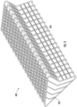
- the flexible reservoir system 400 may include a flexible reservoir 402 and an exoskeleton 404.
- the flexible reservoir 402 may be made of any suitable non-rigid material that allows the flexible reservoir 402 to expand when filled with a liquid or fluid and to contract or collapse when emptied or drained.
- the flexible reservoir 402 may be configured to hold or store any liquid or fluid such as, for example, a liquid drug or other therapeutic agent.
- the flexible reservoir system 400 may be integrated into a drug delivery device or system such as, for example, a wearable or on body drug delivery device such as that described with reference to FIG. 9 .
- the exoskeleton 404 may be formed of any suitable rigid or semi-rigid material such as, for example, metal or plastic.
- the exoskeleton 404 may be attached or coupled to the flexible reservoir 402 along all or a portion of the exoskeleton 404. In various examples, the exoskeleton 404 may be detached or not coupled to the flexible reservoir 402.
- a rigid or semi-rigid exoskeleton 404 may surround the flexible reservoir 402 to guide the expansion and collapse of the flexible reservoir.
- the placement of the exoskeleton 404 creates impingement points or locations on the flexible reservoir 402 that guide the collapse or expansion as fluid leaves or is input to the flexible reservoir 402.
- a volume of the liquid drug stored in the flexible reservoir 402 may be more easily determined to enable accurate fill gauging. For example, hold up volume may also be reduced based on the controlled and predictable manner of collapse of the flexible reservoir 402.
- FIG. 4 shows the flexible reservoir 402 in a filled or partially filled state.
- the flexible reservoir 402 may have a side cross-sectional shape resembling an arrowhead (or triangular) but is not so limited. In general, the flexible reservoir 402 may have any desired size and shape.
- the exoskeleton 404 may conform to the outer surfaces of the flexible reservoir 402 when filled and may operate or be similar to a stent.
- the exoskeleton 404 may have a material that has a higher elastic modulus than the material that forms the flexible reservoir 402.
- the exoskeleton 404 may form a cross-hatching or lattice arrangement (or cage) around the flexible reservoir 402.
- the flexible reservoir 402 may lay substantially flat along with the exoskeleton 104 also being able to fold over, collapse, and/or lay substantially flat on top of and/or around the flexible reservoir 402.
- the exoskeleton 404 may improve fill gauge sensing in relation to the flexible reservoir system 400 as the exoskeleton 404 may ensure that the displacement of the flexible reservoir 402 as it is filled or emptied involves known displacement or movement, allowing the volume of the flexible reservoir to be determined more easily.
- the exoskeleton 404 may reduce hold up volume associated with the flexible reservoir 402 as the controlled collapse of the flexible reservoir 402 provided by the exoskeleton 404 is more predictable and consistent for each collapse.
- FIG. 5 illustrates another example of a flexible reservoir system.
- the flexible reservoir system 410 may include a flexible reservoir 412 and rigid panels 414.
- the flexible reservoir 412 may be made of any suitable non-rigid material that allows the flexible reservoir 412 to expand when filled with a liquid or fluid and to contract or collapse when emptied or drained.
- the flexible reservoir 412 may be configured to hold or store any liquid or fluid such as, for example, a liquid drug or other therapeutic agent.
- the flexible reservoir system 410 may integrated into a drug delivery device or system such as, for example, a wearable or on body drug delivery device.
- the flexible reservoir system 410 may include one or more rigid panels 414, with each rigid panel 414 attached a flat surface of the flexible reservoir 412 as shown.
- the rigid panels 414 may add structure to the flexible reservoir.
- hinge points 416 may be positioned at angled portions or crease portions (or vertices of the different angles) of the flexible reservoir 412.
- the hinge points 416 may be introduced or created by attachment of the rigid panels 414 to the flexible reservoir 412, or by use of the exoskeleton 404 of FIG. 4 .
- the flexible reservoir 412 shown in FIG. 5 is in a filled or partially filled state (e.g., a side view of the flexible reservoir 412).
- the flexible reservoir 412 may have a side cross-sectional shape resembling an arrowhead (or triangular) but is not so limited.
- the flexible reservoir 412 may have any desired size and shape.
- the attachment and positioning of the rigid panels 414 to the flexible reservoir 412 may help determine the shape of the flexible reservoir 412 and may guide the expansion and collapse of the flexible reservoir 412 as it is filled or drained.
- the rigid panels 414 may rotate about the hinge points 416 or rotate relative to one another as the flexible reservoir 412 is filled or emptied.
- the flexible reservoir 412 may be substantially the same as the flexible reservoir 402.
- the placement of the rigid panels 414 may accommodate and guide movement of the flexible reservoir 412 in a controlled and predictable manner.
- the rigid panels 414 may be formed of any suitable material including, for example, metal or plastic. In general, the rigid panels 414 may be formed to be relatively thin in relation to a size of the flexible reservoir 412. The rigid panels 414 may be attached to the flexible reservoir 412 by any suitable means.
- the predictability enables sensors to be used to provide reliable volume sensing (e.g., a fill gauge) so measurements of how much liquid drug remains, has been dispensed and other information related to the volume of the liquid drug, the reservoir or the operation of the wearable device may be provided to a user.
- the materials of the exoskeleton and the flexible reservoir may be the same, or different. To achieve the structural features that enable the predictable collapse or fill of the reservoir, different thicknesses of the same material and/or different materials having a different modulus of elasticity from one another may be used to form the illustrated examples.
- the reservoir systems in a wearable drug delivery system may also be configured to store a liquid drug.
- the fluid path component 606 may include a fill port 610 and may also be coupled to a pumping mechanism 612. As shown in another example, the flow sensor 608 may be positioned between the fill port 610 and the pumping mechanism 612.
- the reservoir 600 may be part of a drug delivery device or system such as, for example, a wearable drug delivery device or system.
- the fill port 610 may provide access to a fluid such as, for example, a liquid drug.
- the pumping mechanism 612 (details not shown in FIG. 6 for simplicity) may be any type of pumping mechanism or system for extracting fluid from the reservoir 602.
- the pumping mechanism 612 may be operated to provide stored fluid within the reservoir to, for example, a user or patient using the wearable drug delivery device of which the reservoir system 600 is a part.
- a first process may be used to form the reservoir 602 and a second or supplemental process may be used to form and position the peel-able restraints 604.
- the peel-able restraints 604 may form zones within the reservoir 602.
- the peel-able restraints 604 may seal or block off portions or sections of the reservoir 602 that may remain sealed until broken during a filling process.
- the peel-able restraints 604 may seal off corresponding sections of the reservoir 602 and may be released or opened as more fluid enters the reservoir 602 during a filling process.
- a pressure/force from the fluid/filling process may cause the peel-able restraints 604 to open or break sequentially, thereby providing access to another corresponding sealed off section of the reservoir 602.
- a filling process of the reservoir 602 may be closely controlled - for example, to ensure that corresponding sections or zones determined by the peel-able restraints 604 are sequentially filled.
- one or more peel-able restraints 604 may be positioned on the reservoir 602 to seal off one or more corresponding sections (i.e., areas between respective peel-able restraints) of the reservoir 602.
- each corresponding section of the one or more corresponding sections is completely filled with the liquid drug before a next section is opened for filling by breaking a next corresponding peel-able restraint.
- the filling process may open any number of the peel-able restraints 604 but is not limited to opening all of the peel-able restraints 604. That is, only a portion of the reservoir 602 may be filled such that some peel-able restraints 604 remain closed, thereby allowing certain corresponding sections of the reservoir 602 to remain sealed off.
- the arrangement of the peel-able restraints 604 may guide the filling process of the reservoir 602 in a predictable and/or controlled manner.
- the peel-able restraints 604 may have increasing widths (e.g., moving from an end of the reservoir 602 coupled to the fluid path component 606 to an end of the reservoir 602 not coupled to the fluid path component 606).
- the increasing widths of the peel-able restraints 604 may provide increasing strengths for the peel-able restraints 604, such that the peel-able restraints 604 having larger widths require more force to open than peel-able restraints 604 having smaller widths. This allows for tuning of the filling of the reservoir 602.
- peel-able restraints 604 open sequentially in a controlled manner - for example, one at a time to provide the fluid to a current corresponding section to first fill completely before opening a next peel-able restraint 604.
- increased pressure needed to break into the next corresponding section may provide a pressure "signature" that may be used for fill sensing.
- the peel-able restraint between a first corresponding section and a second corresponding section may break at 2 pounds per square inch (psi), while the peel-able restraint between the second corresponding section and a third corresponding section may break at 4 psi, so on until the reservoir is filled to a desired volume.
- the respective pressure "signature" for each corresponding section may be the same (e.g. 2.5 psi).
- a fill sensing module which may be a logic circuit or the like coupled to the flow sensor or pressure sensor (e.g., pressure gauge or the like), may detect pressure spikes and pressure drops to infer that a peel-able restraint broke and the liquid drug is flowing into a next corresponding section.
- other methods such as detecting changes in resistance or capacitance may also be used to provide fill sensing with use of a logic circuit.
- the reservoir 602 may have any shape and/or form factor.
- the peel-able restraints 604 may also have any shape and may be arranged in any desired manner onto the reservoir 602.
- the reservoir 602 may be circular and the peel-able restraints 604 may be formed in concentric circles on the reservoir 602.
- the peel-able restraints 604 may be formed along a gradient (e.g., with increasing or decreasing sized corresponding sections).
- the reservoir system 600 may provide several advantages. For example, by establishing separate fillable sections or zones within the reservoir, holdup volume, reservoir air volume, and vapor transmissivity may be reduced.
- the flexible films that form the reservoirs have vapor transmissivity that permits water vapor to pass through the flexible film after time.
- the exposure to water vapor over time can reduce the potency of a drug stored in the reservoir.
- the reservoir 602 related to vapor transmissivity at lower fill volumes, fewer compartments or sections formed by the peel-able restraints 604 may be filled by the fluid or drug. As a result, the interior surface area of the reservoir 602 that contacts the fluid may be reduced (e.g., in comparison to a flexible reservoir not having peel-able restraints 604).
- the rate of vapor transmission to the stored fluid may be reduced (e.g., since the ratio of the surface area of the interior of the reservoir to the fill volume).
- the reservoir 602 is to be filled with a volume of drug that is one-tenth of the capacity of the entire reservoir. Since reservoir 602 has the peel-able restraints 604, by filling a first section or sections equal to the volume of drug, the exposure of the drug to an interior surface area of the reservoir remains at a consistent ratio of fill volume to surface area to which the drug is exposed.
- a reservoir such as 602 may have an interior surface area of 100 square millimeters and assume a volume of drug equaling one-tenth of the fill capacity (i.e., volume of drug that the reservoir is capable of holding) of the reservoir is input into the reservoir.
- the amount of the drug that is exposed to an interior surface of the reservoir may be limited to, for example, one-tenth of the interior surface area of the reservoir.
- the potency of the drug may be prolonged due to the reduced exposure to water vapor.
- the consistent ratio may be based on the particular drug and the material of the flexible film.
- the solution of the liquid drug may pass through the reservoir 602 thereby leaving less liquid volume in the reservoir 602.
- other proteins from the liquid drug may be left behind, which affects drug concentration and potency.
- hold up volume may be reduced at lower fill volumes.
- the peel-able restraints 604 will also maintain a near vacuum state inside the reservoir 602 during storage, preventing trapped air from affecting performance of the reservoir system 600.
- the reservoir system 600 also may provide accurate fill sensing based on detected changes in pressure or flow rate when the peel-able restraints 604 break at known positions.
- the arrangement of the peel-able restraints 604 may cause pressure pulses (e.g., when the dividers are broken) that may correspond to different fill volumes that may be detected by the flow sensor 608.
- the detected flow volume may reflect the changes in pressure related to the fill volume.
- a pressure sensor could also be used in a similar location as the flow sensor 608 to estimate fill volume - for example, by detecting a pressure drop after each restraint (e.g., a peel-able restraint 604) "breaks."
- the sensor 608 may detect changes in pressure and/or flow that may be related to fill volume of the reservoir 602 based on the known positions of the peel-able restraints 604 (and/or the known sizes of the different compartments formed by the peel-able restraints 604).
- Other sensors could also be alternatively used to detect fill volume.
- FIG. 7 illustrates a subsequent exemplary reservoir system 700.
- the reservoir system 700 provides a solution to these somewhat competing goals or requirements for a reservoir by using the thin film reservoir 702 and a separate membrane 704 as a vapor barrier.
- the reservoir system 700 includes a reservoir 702 and an outer membrane 704.
- the reservoir 702 may be a flexible thin film reservoir.
- the outer membrane 704 may be part of or integrated into the housing of wearable drug delivery device (not shown in this example).
- the outer membrane 704 may surround the inner thin film reservoir 702.
- the inner thin film reservoir 702 may include a port or opening 706.
- the outer membrane 704 may be a relatively thick membrane (e.g., in comparison to the thickness of the reservoir 702) and/or have improved water vapor transmissivity than the inner thin film reservoir 702.
- the outer membrane 704 may be configured to reduce or minimize vapor transmission.
- a top view and a corresponding side view of the reservoir system 700 are both shown in FIG. 7 .
- the reservoir 702 and the membrane 704 may be made of the same material (e.g., with different thicknesses). In various examples, the reservoir 702 and the membrane 704 may be made of different materials. In some examples, the reservoir 702 and the membrane 704 may not be laminated together, but in other example, the reservoir 702 and the membrane 704 may be laminated together.
- FIG. 8 illustrates exemplary processes for forming a multilayer reservoir.
- the processes may be used to form the reservoirs 602 or 202.
- a first membrane material 802 may be die cut by a cutter 806.
- the first membrane material 802 may then be laminated to a second membrane material 804 by a laminator 808.
- the second material 804 may be configured to function as a localized stiffener.
- the first membrane material 802 may be a thin film that is easy to bend.
- the second membrane material 804 may provide a good vapor barrier and may be stiffer than the first membrane material 802.
- the first membrane material 802 or the second membrane material 804 may be configured to contact the drug and be utilized as an interior surface of a reservoir.
- the process shown in the top figure of FIG. 8 provides a technique for joining materials with different benefits to form a multilayer reservoir with localized stiffener.
- the second membrane material 804 may be polychlorotrifluoroethylene (PCTFE) (also referred to by the brand name Aclar ® ) or the like.
- PCTFE polychlorotrifluoroethylene
- the laminated result shown in the top process may provide localized areas that facilitate easier folding, manufacturing, and consistent collapse of a flexible reservoir, while maintaining desired vapor barrier properties across most of the surface area as a result of the lamination.
- the top and bottom materials 812 may be of the same material as the first membrane material 802 in the top figure of FIG. 8 or the materials 812 may be a different.
- the middle material 814 may be a different material than the membrane material 804.
- the material 812 on the top and bottom may be laminated together through die cut holes (e.g., formed by cutter 806) formed in the middle material 814.
- the middle material 814 may provide enhanced vapor barrier properties.
- ⁇ 8 may allow the formation of a multilayer reservoir using dissimilar materials that may be hard to laminate together - accordingly, holes in the middle layer material are formed such that lamination of the materials 812 to one another may form the multilayer reservoir by coupling the outer similar material 812 layers together.
- Such an arrangement may be beneficial because it provides both the flexibility required for a collapsible reservoir as well as the vapor barrier properties desired to mitigate against loss of potency of any liquid drug within the reservoir.
- Examples of materials suitable for use in producing the respective flexible films of the examples shown in FIGs. 1-8 include low-density polyethylene, polypropylene, polypropylene/ PCTFE laminate, PCTFE, Aclar CP or the like.
- FIG. 9 illustrates an example of a wearable drug delivery device suitable for use with the reservoir examples of FIGs. 1-7 .
- the wearable drug delivery device 900 includes housing 901, a reservoir 920, a fluid path component 906, and a pump 912.
- the wearable drug delivery device 900 may be attached to a user via an adhesive tape or the like.
- the housing 901 may also be a chassis for the wearable drug delivery device.
- the reservoir 920 may be a flexible thin film reservoir (as shown in the examples of FIGs. 6-8 ), a shell/flexible film hybrid reservoir (such as the examples shown in FIGs. 1-3 ), a flexible reservoir with exoskeleton (as shown in the examples of FIGs.
- the reservoir 920 includes a shell component, such as 102, 202 and 302 of FIGs. 1-3
- the shell component may be integrated into other parts of the wearable drug delivery device, such as the housing 901, thereby enabling the rigid or semi-rigid shell component of the reservoir 920 to serve multiple purposes, such as a backside of a housing for the wearable drug delivery device 900, or the like.
- the fluid path component 906 may be coupled to the reservoir 920.
- the fluid path component 906 may include a fill port 910 and may also be coupled to a pumping mechanism 912.
- a flow sensor 908 suitable for use in determining a volume of drug delivered may be positioned within the fluid path component 906 between the fill port 910 and the pumping mechanism 912. Alternatively, a flow sensor 908 may be near the entrance of the reservoir 920 so a drug volume input to the reservoir 920 may be determined.
- the reservoir system of FIG. 6 may be used and may include a fluid path component 906 of the wearable drug delivery device 900 coupled to the reservoir 920 and a pumping mechanism, with the pumping mechanism configured to extract a fluid contained in the reservoir.
- a flow sensor 908 may be coupled between a fill port of the fluid path and the pumping mechanism and may detect a fill volume of the reservoir based on pressure changes or flow changes as the peel-able restraints sequentially break. Further, the breaking of peel-able restraints positioned at known locations may provide for fill sensing.
- a vapor barrier membrane such as 704 in the example of FIG. 7 , may be positioned around the reservoir 920 to reduce vapor transmission.
- the fill port 910 may provide access to a fluid such as, for example, a liquid drug.
- the pumping mechanism 912 may be any type of pumping mechanism or system for extracting fluid from the reservoir 920. Examples of pump mechanisms suitable for use as pump mechanism 912 may be found in U.S. Patent Application Nos. 16/433,481 filed on June 6, 2019 and 16/054,323 filed on August 3, 2018 , the entire contents of each application incorporated herein by reference. Of course, other pump mechanisms may be used.
- the pump mechanism 912 may be coupled to a fluid path 913 and a needle or cannula 940.
- the needle or cannula 940 may be configured to complete a fluid pathway from the fluid path 913 to a user by fluidly coupling to the fluid path 913 and penetrating the skin of the user (not shown).
- the pumping mechanism 912 may be operated to provide fluid stored within the reservoir 920 for example, via the fluid path 913 and needle/cannula 940 to a user or patient wearing the wearable drug delivery device 900.
- An example of a system for delivering drugs is provided in U.S. Patent Application No. 15/359,187, filed November 22, 2016 , which is herein incorporated by reference in its entirety.
- the wearable drug delivery device 900 may also include a logic circuit and a power supply 988.
- the logic circuit may be coupled to the pump mechanism 912, the flow sensor 908 and optionally other components, such as the peel-able constraints, when the reservoir example of FIG. 6 is utilized.
- An example of a suitable power supply may be batteries, or the like.
- the logic circuit and power supply 988 may include a memory (not shown) for storing programming code and information.
- the logic circuit and power supply 988 may be configured to control and receive inputs from the pump mechanism 912, the flow sensor 908 and other components, such as the peel-able constraints, if present.
- the logic circuit and power supply 988 may be configured to and perform calculations and processes based on inputs received from inputs from the pump mechanism 912, the flow sensor 908, and other components, such as the peel-able constraints, or the like.
Landscapes
- Health & Medical Sciences (AREA)
- Veterinary Medicine (AREA)
- Animal Behavior & Ethology (AREA)
- General Health & Medical Sciences (AREA)
- Life Sciences & Earth Sciences (AREA)
- Public Health (AREA)
- Hematology (AREA)
- Heart & Thoracic Surgery (AREA)
- Biomedical Technology (AREA)
- Vascular Medicine (AREA)
- Anesthesiology (AREA)
- Engineering & Computer Science (AREA)
- Dermatology (AREA)
- Pharmacology & Pharmacy (AREA)
- Physics & Mathematics (AREA)
- Fluid Mechanics (AREA)
- Infusion, Injection, And Reservoir Apparatuses (AREA)
- Medical Preparation Storing Or Oral Administration Devices (AREA)
Description
- The present application generally relates to medication delivery devices, and more particularly to reservoirs or reservoirs for storing a liquid drug within a drug delivery device.
- Many conventional wearable drug delivery systems include either a fully rigid reservoir or a fully flexible reservoir for storing a liquid drug. Each type of reservoir includes one or more advantages and disadvantages over the other type of reservoir. Fully rigid reservoirs take up space that may be better used. While fully flexible reservoirs may be space efficient and may require relatively lower pumping pressures, the flexible reservoirs present challenges compared to fully rigid reservoirs. For example, the expansion and collapse of earlier flexible reservoirs may be unpredictable, thereby leading to undesirable hold up volumes and difficulties in determining stored fluid volumes (e.g., inaccurate fill gauging). Flexible reservoirs also present challenges related to vapor transmissivity. In some instances, a small volume of fluid is spread across a large surface area on a thin flexible membrane. This may lead to higher vapor transmission rates and may negatively impact medication concentration/potency.
WO 2012/065780 A2 discloses a reservoir for storing a liquid drug, the reservoir comprising a shell component and a flexible component coupled thereto. A similar reservoir is known fromEP 2 556 815 A1 , which represents prior art under Article 54(3) EPC. In both cases, the flexible component does not deflate and conform to the inner surface of the shell component. - The invention comprises a reservoir for storing a liquid drug as defined in
claim 1. Additional features of preferred embodiments are defined in the dependent claims. Disclosed is an example of a reservoir for storing a liquid drug. The reservoir includes a shell component, a flexible component and a port. The flexible component is coupled to the shell component. The coupling is a hermetic seal. The port is configured to enable filling of emptying of the reservoir. - An example of a reservoir system is disclosed that includes a flexible reservoir and an exoskeleton. The flexible reservoir is configured to expand when filled with a liquid drug. The exoskeleton is coupled to the flexible reservoir.
- A system example is disclosed in which the system include a reservoir, one or more peel-able restraints positioned on the flexible reservoir. The one or more peel-able restraints are configured to seal off one or more corresponding sections of the flexible reservoir, and sequentially break to allow a liquid to fill a next corresponding section of the one or more corresponding sections of the flexible reservoir as the flexible reservoir is filled with the liquid.
-
-
FIG. 1 illustrates a cross-sectional side view of a first example of a drug reservoir in a filled state and an unfilled state according to the disclosure. -
FIG. 2 illustrates a top view and a corresponding side view of an embodiment of a drug reservoir according to the invention. -
FIG. 3 illustrates a top view and a corresponding side view of further embodiment of a drug reservoir according to the invention. -
FIG. 4 illustrates an example of a flexible reservoir system. -
FIG. 5 illustrates another example of a flexible reservoir system. -
FIG. 6 illustrates a subsequent example of a reservoir. -
FIG. 7 illustrates an additional example of a reservoir. -
FIG. 8 illustrates examples of processes for forming a multilayer reservoir. -
FIG. 9 illustrates an example of a wearable drug delivery device suitable for use with the reservoir examples ofFIGs. 1-7 . - Various systems, components, and methods related to drug delivery devices are disclosed. Each of the systems, components, and methods disclosed herein provides one or more advantages over conventional systems, components, and methods.
- In order to mitigate the foregoing disadvantages of flexible reservoirs, a need therefore exists for a drug delivery device that includes a drug reservoir or reservoir that combines the advantages of fully flexible and fully rigid reservoirs while mitigating one or more disadvantages of fully flexible and fully rigid reservoirs. In addition, there is a need for a flexible reservoir system that may expand and collapse in a more predictable manner, to reduce hold up volumes and enable accurate stored fluid volume determinations, while retaining the advantages of flexible reservoirs such as high space efficiency or low pumping pressure. A further need exists for a flexible reservoir for use with a drug delivery device that has reduced holdup volume, reduced vapor transmission, and improved fill sensing capabilities.
-
FIG. 1 illustrates a cross-sectional side view of a first example of a drug reservoir in a filled state and an unfilled state. The combination of components for forming the reservoir (or hybrid reservoir) may, for example, allow the liquid drug to be stored and then expelled from the reservoir with relatively lower pumping pressures (as compared to fully rigid drug reservoirs) and without the need for a plunger as well as other apparent advantages. - As shown, the
drug reservoir 100 includes ashell component 102 that may be rigid or semi-rigid and aflexible component 104. Theshell component 102 may be formed from a variety of materials including, for example, plastic or metal, or any combination thereof. Theflexible component 104 may be formed from a variety of flexible materials including, for example, a flexible plastic film. Theflexible component 104 has greater flexibility than theshell component 102.FIG. 1 shows thedrug reservoir 100 in an unfilled state and in a filled state. When filled, theflexible component 104 expands in response to a liquid drug (not shown) filling thedrug reservoir 100 from a port (shown in other examples). The expansion of theflexible component 104 and the hermetic coupling or seal to theshell component 102 enables thedrug reservoir 100 to contain a liquid drug (or other fluid or therapeutic agent) 106. Theshell component 102 is an open shell. In some examples of a wearable drug delivery device, theshell component 102 may be integrated into other parts, such as a housing or chassis thereby enabling a rigid orsemi-rigid shell component 102 to serve multiple purposes, such as part of a housing for the wearable drug delivery device, a structure element of another part (e.g. a battery clip or retainer) of the wearable drug delivery device, or the like. - The
flexible component 104 may be coupled to theshell component 102 in a number of manners including, for example, mechanically, through use of an adhesive, or through use of an adhesive tape or the like. The coupling of theflexible component 104 to theshell component 102 is a hermetic seal thereby forming thereservoir 100 that is able to contain the liquid drug or other fluid. Theshell component 102 may be of any size or shape. As shown inFIG. 1 , theshell component 102 may form a bowl with an upper ridge or lip to support and provide coupling to theflexible component 104. -
FIG. 2 illustrates a top view and a corresponding side view of a second example of a drug reservoir. Thedrug reservoir 200 may be a particular implementation of thedrug reservoir 100. Thedrug reservoir 200 may include a rigid orsemi-rigid shell component 202 and a flexible component 204. The flexible component 204 may be formed from a thin flexible film, or the like. Theshell component 202 may be an open shell. Although not shown inFIG. 2 , the flexible component 204 may be sealed (i.e., coupled to form hermetic seal) to the shell component 202 - for example, along a perimeter of theshell component 202. For example, an adhesive, an adhesive tape or mechanical means, such as ultrasonic welding or the like, may be used to couple or affix the flexible film component to theshell component 202. The sealing of the flexible component 204 to theshell component 202 is hermetic thereby forming thereservoir 200 that contains the liquid drug or other fluid. The side view shows the flexible component 204 in a deflated state 204-1 and in an inflated or expanded state 204-2 when filled with a fluid. When inflated or expanded, the flexible component 204 may provide achamber 208 for storing a fluid. - The
drug reservoir 200 may further include an opening orside port 206. Theside port 206 may be coupled to a fluid extraction component such as, for example, a pump (not shown). Theside port 206 may also be coupled to a fluid path (not shown) coupled to a patient or user of a wearable drug device containing thedrug reservoir 200. Theside port 206 may be formed as a portion of theshell component 202 or may be a separate component coupled to thedrug reservoir 200. A liquid drug or other fluid may enter and/or exit thedrug reservoir 200 from theside port 206. - As shown in the top view and the side view, the
drug reservoir 200 may further include one or more recesseddrainage channels 210. Thedrainage channels 210 may be formed into theshell component 202, for example, into an inner surface of theshell component 202. In an alternative example, thedrainage channels 210, instead of being formed in theshell component 202, may be formed into the flexible component 204, for example, into an inner surface (i.e., inside thedrug reservoir 200 at a surface that contacts the liquid) of the flexible component 204. In yet another alternative example, thedrainage channels 210 may be formed in theshell component 202 and the flexible component 204, for example, in an inner surface of each of theshell component 202 and the flexible component 204. Thedrainage channels 210 may improve drainage of thedrug reservoir 200, particularly as thedrug reservoir 200 is nearly emptied of a stored liquid drug. - The
drainage channels 210 may be formed in a number of ways to form any pattern or arrangement. In various examples, thedrainage channels 210 may be formed to mimic venation patterns found on leaves. As an example, thedrainage channels 210 may form a pinnate pattern or arrangement (e.g., a specific form of venation and may include a single mid-rib channel and secondary channels branching therefrom). In other examples, thedrainage channels 210 may be a number of horizontal and vertical channels that are perpendicular to one another (e.g., a form of cross hatching), diagonal channels, or similar patterns of channels that facilitate drainage of the reservoir to minimize an amount of hold up volume (e.g., a volume of liquid) in the reservoir after the reservoir is drained. In addition, the channels may be a similar depth along the entire length of the channel or may have a graded depth to facilitate flow toward a port. Alternatively, or in addition, the interior of the reservoir on the film 204, theshell 202 or both may have a textured surface, such as stippling (e.g., bumps), ridges, grooves, or the like, configured to minimize the surface area upon which surfaces of film 204 and shell 202 at the interior of thereservoir 200 may contact one another as the fluid evacuates the reservoir. -
FIG. 3 illustrates a top view and a corresponding side view of a third example of a drug reservoir according to the disclosure. Thedrug reservoir 300 may include a rigid orsemi-rigid shell component 302 and a flexible film component 304. The flexible film component 304 may be sealed or coupled to the shell component 302 - for example, along a perimeter of theshell component 302, to form a hermetic seal between the flexible film component 304 and theshell component 302. The corresponding side view ofdrug reservoir 300 shows the flexible film component 304 in a deflated state 304-1 and in an inflated or expanded state 304-2. When inflated or expanded, the flexible film component 304 may provide achamber 308 for storing a fluid. - The
drug reservoir 300 may further include an opening orcentral face port 306. Thecentral face port 306 may be coupled to a fluid extraction component such as, for example, a pump. Thecentral face port 306 may also be coupled to a fluid path coupled to a patient or user of a wearable drug device containing thedrug reservoir 300. Thecentral face port 306 may include a pierceable septum accessible from a bottom side of thedrug reservoir 300. Thecentral face port 306 may be formed as part of theshell component 302 or may be a separate component coupled to thedrug reservoir 300. A liquid drug or other fluid may enter and/or exit from thecentral face port 306. - The
drug reservoir 300 may further include one or more recesseddrainage channels 310. Thechannels 310 may be formed into the shell component 302 (e.g., an inner surface of the shell component 302). Thechannels 310 may improve drainage of thedrug reservoir 300, particularly as thedrug reservoir 300 is nearly emptied of a stored liquid drug. For example, the circular region at the intersection of thechannels 310 may be coupled to the pierce-able septum at the bottom of the pod andcentral face port 306 to allow the drug (not shown) to drain from thedrug reservoir 300. - The
channels 310 may be formed in a number of ways to form any pattern or arrangement. In various examples, thechannels 310 may be formed to mimic venation patterns found on leaves. As an example, thechannels 310 may form a palmate pattern or arrangement (e.g., a specific form of venation to include multiple primary channels with additional subchannels branching from a central point). In other examples, thedrainage channels 210 may be a pattern of a number of horizontal and vertical channels that are perpendicular to one another (e.g., a form of cross hatching), diagonal channels, or similar patterns of channels. - Overall, the
channels channels channels drug reservoirs - By joining an open rigid (or semi-rigid) shell component and a flexible film sealing the open rigid shell component, the drug reservoirs disclosed herein (e.g., the
drug reservoirs drug reservoirs example drug reservoirs - In various examples, the
flexible film components 104, 204 and 304 disclosed herein may be coupled or sealed to theshell components - In various examples, the
flexible film components 104, 204 and 304 disclosed herein may be formed to provide a tight seal with theshell components flexible film components 104, 204 and 304 may be provided by thermoforming. - Each of the drug reservoirs disclosed herein (e.g., the
drug reservoirs FIG. 9 . -
FIG. 4 illustrates an example of a flexible reservoir system. Theflexible reservoir system 400 may include aflexible reservoir 402 and anexoskeleton 404. Theflexible reservoir 402 may be made of any suitable non-rigid material that allows theflexible reservoir 402 to expand when filled with a liquid or fluid and to contract or collapse when emptied or drained. Theflexible reservoir 402 may be configured to hold or store any liquid or fluid such as, for example, a liquid drug or other therapeutic agent. - The
flexible reservoir system 400 may be integrated into a drug delivery device or system such as, for example, a wearable or on body drug delivery device such as that described with reference toFIG. 9 . Theexoskeleton 404 may be formed of any suitable rigid or semi-rigid material such as, for example, metal or plastic. Theexoskeleton 404 may be attached or coupled to theflexible reservoir 402 along all or a portion of theexoskeleton 404. In various examples, theexoskeleton 404 may be detached or not coupled to theflexible reservoir 402. - A rigid or
semi-rigid exoskeleton 404 may surround theflexible reservoir 402 to guide the expansion and collapse of the flexible reservoir. The placement of theexoskeleton 404 creates impingement points or locations on theflexible reservoir 402 that guide the collapse or expansion as fluid leaves or is input to theflexible reservoir 402. As a result, a volume of the liquid drug stored in theflexible reservoir 402 may be more easily determined to enable accurate fill gauging. For example, hold up volume may also be reduced based on the controlled and predictable manner of collapse of theflexible reservoir 402. -
FIG. 4 shows theflexible reservoir 402 in a filled or partially filled state. As shown, theflexible reservoir 402 may have a side cross-sectional shape resembling an arrowhead (or triangular) but is not so limited. In general, theflexible reservoir 402 may have any desired size and shape. Theexoskeleton 404 may conform to the outer surfaces of theflexible reservoir 402 when filled and may operate or be similar to a stent. Theexoskeleton 404 may have a material that has a higher elastic modulus than the material that forms theflexible reservoir 402. As further shown inFIG. 4 , theexoskeleton 404 may form a cross-hatching or lattice arrangement (or cage) around theflexible reservoir 402. In an unfilled or compressed state, theflexible reservoir 402 may lay substantially flat along with theexoskeleton 104 also being able to fold over, collapse, and/or lay substantially flat on top of and/or around theflexible reservoir 402. - The flexible reservoir system 400 - by including the exoskeleton 404 - may improve control of the expansion and the collapse of the
flexible reservoir 402 during filling and emptying of the flexible reservoir, respectively. The rigid and/or semi-shell components of theexoskeleton 404 may aid or guide the change of shape of theflexible reservoir 402 such that as it expands or collapses, it does so in a predictable and expected manner. By guiding the expansion and collapse of theflexible reservoir 402, theexoskeleton 404 may improve operation of theflexible reservoir system 400. - In particular, the
exoskeleton 404 may improve fill gauge sensing in relation to theflexible reservoir system 400 as theexoskeleton 404 may ensure that the displacement of theflexible reservoir 402 as it is filled or emptied involves known displacement or movement, allowing the volume of the flexible reservoir to be determined more easily. - Additionally, the
exoskeleton 404 may reduce hold up volume associated with theflexible reservoir 402 as the controlled collapse of theflexible reservoir 402 provided by theexoskeleton 404 is more predictable and consistent for each collapse. -
FIG. 5 illustrates another example of a flexible reservoir system. Theflexible reservoir system 410 may include aflexible reservoir 412 andrigid panels 414. Theflexible reservoir 412 may be made of any suitable non-rigid material that allows theflexible reservoir 412 to expand when filled with a liquid or fluid and to contract or collapse when emptied or drained. Theflexible reservoir 412 may be configured to hold or store any liquid or fluid such as, for example, a liquid drug or other therapeutic agent. - The
flexible reservoir system 410 may integrated into a drug delivery device or system such as, for example, a wearable or on body drug delivery device. Theflexible reservoir system 410 may include one or morerigid panels 414, with eachrigid panel 414 attached a flat surface of theflexible reservoir 412 as shown. Therigid panels 414 may add structure to the flexible reservoir. As shown inFIG. 5 , hinge points 416 may be positioned at angled portions or crease portions (or vertices of the different angles) of theflexible reservoir 412. The hinge points 416 may be introduced or created by attachment of therigid panels 414 to theflexible reservoir 412, or by use of theexoskeleton 404 ofFIG. 4 . - The
flexible reservoir 412 shown inFIG. 5 is in a filled or partially filled state (e.g., a side view of the flexible reservoir 412). As shown, theflexible reservoir 412 may have a side cross-sectional shape resembling an arrowhead (or triangular) but is not so limited. In general, theflexible reservoir 412 may have any desired size and shape. The attachment and positioning of therigid panels 414 to theflexible reservoir 412 may help determine the shape of theflexible reservoir 412 and may guide the expansion and collapse of theflexible reservoir 412 as it is filled or drained. In various examples, therigid panels 414 may rotate about the hinge points 416 or rotate relative to one another as theflexible reservoir 412 is filled or emptied. - In various examples, the
flexible reservoir 412 may be substantially the same as theflexible reservoir 402. The placement of therigid panels 414 may accommodate and guide movement of theflexible reservoir 412 in a controlled and predictable manner. Therigid panels 414 may be formed of any suitable material including, for example, metal or plastic. In general, therigid panels 414 may be formed to be relatively thin in relation to a size of theflexible reservoir 412. Therigid panels 414 may be attached to theflexible reservoir 412 by any suitable means. - The
rigid panels 414 may facilitate volume determination of a fluid occupying theflexible reservoir 412. For example, angles of theflexible reservoir 412, angles of the created hinge points 416, and/or movement or displacement of the rigid panels 204 (e.g., relative to one another or to a fixed reference point) may be used to estimate an amount of fluid contained within theflexible reservoir 412 as each of these components and features of theflexible reservoir system 410 change upon expansion and collapse. As with theflexible reservoir system 400, theflexible reservoir system 410 may reduce hold up volume as the rigid panels provide controlled collapse of theflexible reservoir 412 during the evacuation of fluid from theflexible reservoir 410, resulting in a more predictable and consistent collapse of theflexible reservoir 410. The examples inFIGs. 4 and5 provide a reservoir system that fills and empties in a predictable manner due to the use of the exoskeleton. The predictability enables sensors to be used to provide reliable volume sensing (e.g., a fill gauge) so measurements of how much liquid drug remains, has been dispensed and other information related to the volume of the liquid drug, the reservoir or the operation of the wearable device may be provided to a user. The materials of the exoskeleton and the flexible reservoir may be the same, or different. To achieve the structural features that enable the predictable collapse or fill of the reservoir, different thicknesses of the same material and/or different materials having a different modulus of elasticity from one another may be used to form the illustrated examples. - In the various examples of
FIGs. 6-8 of another reservoir system, the reservoir systems in a wearable drug delivery system, for example, may also be configured to store a liquid drug. -
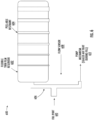
FIG. 6 illustrates a first example of a reservoir. As shown inFIG. 6 , thereservoir 600 may include areservoir 602 and peel-able restraints (or dividers) 604. Thereservoir 600 may couple to afluid path component 606 that includes aflow sensor 608 and to a pumping mechanism 612 (not shown but described in more detail with reference to another example). Thereservoir 602 may be a flexible thin film reservoir. The peel-able restraints 604 may be peel-able heat stakes or the like. For example, the peel-able restraints 604 may be held together with a weak adhesive having known holding properties or the like. Thefluid path component 606 may be coupled to thereservoir 602. Thefluid path component 606 may include afill port 610 and may also be coupled to apumping mechanism 612. As shown in another example, theflow sensor 608 may be positioned between thefill port 610 and thepumping mechanism 612. Thereservoir 600 may be part of a drug delivery device or system such as, for example, a wearable drug delivery device or system. - In various examples, the
fill port 610 may provide access to a fluid such as, for example, a liquid drug. The pumping mechanism 612 (details not shown inFIG. 6 for simplicity) may be any type of pumping mechanism or system for extracting fluid from thereservoir 602. Thepumping mechanism 612 may be operated to provide stored fluid within the reservoir to, for example, a user or patient using the wearable drug delivery device of which thereservoir system 600 is a part. - In various examples, a first process may be used to form the
reservoir 602 and a second or supplemental process may be used to form and position the peel-able restraints 604. The peel-able restraints 604 may form zones within thereservoir 602. The peel-able restraints 604 may seal or block off portions or sections of thereservoir 602 that may remain sealed until broken during a filling process. For example, the peel-able restraints 604 may seal off corresponding sections of thereservoir 602 and may be released or opened as more fluid enters thereservoir 602 during a filling process. A pressure/force from the fluid/filling process may cause the peel-able restraints 604 to open or break sequentially, thereby providing access to another corresponding sealed off section of thereservoir 602. In this manner, a filling process of thereservoir 602 may be closely controlled - for example, to ensure that corresponding sections or zones determined by the peel-able restraints 604 are sequentially filled. In an operational example, one or more peel-able restraints 604 may be positioned on thereservoir 602 to seal off one or more corresponding sections (i.e., areas between respective peel-able restraints) of thereservoir 602. In an example, each corresponding section of the one or more corresponding sections is completely filled with the liquid drug before a next section is opened for filling by breaking a next corresponding peel-able restraint. An initial section (e.g., the section of thereservoir 602 closest to the fluid path component 606) of thereservoir 602 may be filled, eventually a first peel-able restraint (closest to the fluid path component 606) of the peel-able restraints 604 may sequentially break, enabling the liquid drug to sequentially fill the corresponding section of thereservoir 602. In this way, thereservoir 602 is filled in a predictable and controlled manner - with each section formed by the peel-able restraints filled one after another. - In various examples, the filling process may open any number of the peel-
able restraints 604 but is not limited to opening all of the peel-able restraints 604. That is, only a portion of thereservoir 602 may be filled such that some peel-able restraints 604 remain closed, thereby allowing certain corresponding sections of thereservoir 602 to remain sealed off. In general, the arrangement of the peel-able restraints 604 may guide the filling process of thereservoir 602 in a predictable and/or controlled manner. - As shown in
FIG. 6 , the peel-able restraints 604 may have increasing widths (e.g., moving from an end of thereservoir 602 coupled to thefluid path component 606 to an end of thereservoir 602 not coupled to the fluid path component 606). The increasing widths of the peel-able restraints 604 may provide increasing strengths for the peel-able restraints 604, such that the peel-able restraints 604 having larger widths require more force to open than peel-able restraints 604 having smaller widths. This allows for tuning of the filling of thereservoir 602. The arrangement and increasing widths of the peel-able restraints 604 as shown inFIG. 6 may ensure that the peel-able restraints 604 open sequentially in a controlled manner - for example, one at a time to provide the fluid to a current corresponding section to first fill completely before opening a next peel-able restraint 604. In an example, increased pressure needed to break into the next corresponding section may provide a pressure "signature" that may be used for fill sensing. For example, the peel-able restraint between a first corresponding section and a second corresponding section may break at 2 pounds per square inch (psi), while the peel-able restraint between the second corresponding section and a third corresponding section may break at 4 psi, so on until the reservoir is filled to a desired volume. Alternatively, the respective pressure "signature" for each corresponding section may be the same (e.g. 2.5 psi). A fill sensing module, which may be a logic circuit or the like coupled to the flow sensor or pressure sensor (e.g., pressure gauge or the like), may detect pressure spikes and pressure drops to infer that a peel-able restraint broke and the liquid drug is flowing into a next corresponding section. Of course, other methods such as detecting changes in resistance or capacitance may also be used to provide fill sensing with use of a logic circuit. - The
reservoir 602 may have any shape and/or form factor. The peel-able restraints 604 may also have any shape and may be arranged in any desired manner onto thereservoir 602. In an example, thereservoir 602 may be circular and the peel-able restraints 604 may be formed in concentric circles on thereservoir 602. In an example, the peel-able restraints 604 may be formed along a gradient (e.g., with increasing or decreasing sized corresponding sections). - The
reservoir system 600 may provide several advantages. For example, by establishing separate fillable sections or zones within the reservoir, holdup volume, reservoir air volume, and vapor transmissivity may be reduced. - In some instances, the flexible films that form the reservoirs have vapor transmissivity that permits water vapor to pass through the flexible film after time. The exposure to water vapor over time can reduce the potency of a drug stored in the reservoir. As a further advantage of the
reservoir 602 related to vapor transmissivity, at lower fill volumes, fewer compartments or sections formed by the peel-able restraints 604 may be filled by the fluid or drug. As a result, the interior surface area of thereservoir 602 that contacts the fluid may be reduced (e.g., in comparison to a flexible reservoir not having peel-able restraints 604). By reducing the interior surface area of thereservoir 602 in contact with the fluid, the rate of vapor transmission to the stored fluid may be reduced (e.g., since the ratio of the surface area of the interior of the reservoir to the fill volume). For example, thereservoir 602 is to be filled with a volume of drug that is one-tenth of the capacity of the entire reservoir. Sincereservoir 602 has the peel-able restraints 604, by filling a first section or sections equal to the volume of drug, the exposure of the drug to an interior surface area of the reservoir remains at a consistent ratio of fill volume to surface area to which the drug is exposed. For example, a reservoir, such as 602, may have an interior surface area of 100 square millimeters and assume a volume of drug equaling one-tenth of the fill capacity (i.e., volume of drug that the reservoir is capable of holding) of the reservoir is input into the reservoir. By using areservoir 602 having the peel-able restraints 604, the amount of the drug that is exposed to an interior surface of the reservoir may be limited to, for example, one-tenth of the interior surface area of the reservoir. By maintaining a consistent ratio of exposed interior surface area to liquid drug volume, the potency of the drug may be prolonged due to the reduced exposure to water vapor. The consistent ratio may be based on the particular drug and the material of the flexible film. In other examples, the solution of the liquid drug may pass through thereservoir 602 thereby leaving less liquid volume in thereservoir 602. In addition, other proteins from the liquid drug may be left behind, which affects drug concentration and potency. - Furthermore, hold up volume may be reduced at lower fill volumes. The peel-
able restraints 604 will also maintain a near vacuum state inside thereservoir 602 during storage, preventing trapped air from affecting performance of thereservoir system 600. - The
reservoir system 600 also may provide accurate fill sensing based on detected changes in pressure or flow rate when the peel-able restraints 604 break at known positions. For example, the arrangement of the peel-able restraints 604 may cause pressure pulses (e.g., when the dividers are broken) that may correspond to different fill volumes that may be detected by theflow sensor 608. The detected flow volume may reflect the changes in pressure related to the fill volume. Alternatively, a pressure sensor could also be used in a similar location as theflow sensor 608 to estimate fill volume - for example, by detecting a pressure drop after each restraint (e.g., a peel-able restraint 604) "breaks." In general, thesensor 608 may detect changes in pressure and/or flow that may be related to fill volume of thereservoir 602 based on the known positions of the peel-able restraints 604 (and/or the known sizes of the different compartments formed by the peel-able restraints 604). Other sensors could also be alternatively used to detect fill volume. - Often, the desire for a thin and flexible reservoir may make it challenging to make the reservoir less susceptible or prone to vapor transmission.
FIG. 7 illustrates a subsequentexemplary reservoir system 700. Thereservoir system 700 provides a solution to these somewhat competing goals or requirements for a reservoir by using thethin film reservoir 702 and aseparate membrane 704 as a vapor barrier. As shown inFIG. 7 , thereservoir system 700 includes areservoir 702 and anouter membrane 704. Thereservoir 702 may be a flexible thin film reservoir. In an example, in configurations where an amount of free space or air volume is to be limited at maximum fill of thereservoir system 700, theouter membrane 704 may be part of or integrated into the housing of wearable drug delivery device (not shown in this example). In another example, theouter membrane 704 may surround the innerthin film reservoir 702. The innerthin film reservoir 702 may include a port oropening 706. Theouter membrane 704 may be a relatively thick membrane (e.g., in comparison to the thickness of the reservoir 702) and/or have improved water vapor transmissivity than the innerthin film reservoir 702. Theouter membrane 704 may be configured to reduce or minimize vapor transmission. A top view and a corresponding side view of thereservoir system 700 are both shown inFIG. 7 . - By doing so, each component may be separately optimized to meet overall design requirements. In various examples, the
reservoir 702 and themembrane 704 may be made of the same material (e.g., with different thicknesses). In various examples, thereservoir 702 and themembrane 704 may be made of different materials. In some examples, thereservoir 702 and themembrane 704 may not be laminated together, but in other example, thereservoir 702 and themembrane 704 may be laminated together. -
FIG. 8 illustrates exemplary processes for forming a multilayer reservoir. The processes may be used to form thereservoirs first membrane material 802 may be die cut by acutter 806. Thefirst membrane material 802 may then be laminated to asecond membrane material 804 by alaminator 808. For example, thesecond material 804 may be configured to function as a localized stiffener. In an example, thefirst membrane material 802 may be a thin film that is easy to bend. In an example, thesecond membrane material 804 may provide a good vapor barrier and may be stiffer than thefirst membrane material 802. Alternatively, in the top figure, thefirst membrane material 802 or thesecond membrane material 804 may be configured to contact the drug and be utilized as an interior surface of a reservoir. - The process shown in the top figure of
FIG. 8 provides a technique for joining materials with different benefits to form a multilayer reservoir with localized stiffener. In an example, thesecond membrane material 804 may be polychlorotrifluoroethylene (PCTFE) (also referred to by the brand name Aclar®) or the like. The laminated result shown in the top process may provide localized areas that facilitate easier folding, manufacturing, and consistent collapse of a flexible reservoir, while maintaining desired vapor barrier properties across most of the surface area as a result of the lamination. - In the bottom figure of
FIG. 8 , the top andbottom materials 812 may be of the same material as thefirst membrane material 802 in the top figure ofFIG. 8 or thematerials 812 may be a different. Themiddle material 814 may be a different material than themembrane material 804. Thematerial 812 on the top and bottom may be laminated together through die cut holes (e.g., formed by cutter 806) formed in themiddle material 814. Again, in an example, themiddle material 814 may provide enhanced vapor barrier properties. The process shown in this bottom figure ofFIG. 8 may allow the formation of a multilayer reservoir using dissimilar materials that may be hard to laminate together - accordingly, holes in the middle layer material are formed such that lamination of thematerials 812 to one another may form the multilayer reservoir by coupling the outersimilar material 812 layers together. Such an arrangement may be beneficial because it provides both the flexibility required for a collapsible reservoir as well as the vapor barrier properties desired to mitigate against loss of potency of any liquid drug within the reservoir. - Examples of materials suitable for use in producing the respective flexible films of the examples shown in
FIGs. 1-8 include low-density polyethylene, polypropylene, polypropylene/ PCTFE laminate, PCTFE, Aclar CP or the like. -
FIG. 9 illustrates an example of a wearable drug delivery device suitable for use with the reservoir examples ofFIGs. 1-7 . As shown inFIG. 9 , the wearabledrug delivery device 900 includes housing 901, areservoir 920, afluid path component 906, and apump 912. Although not shown, the wearabledrug delivery device 900 may be attached to a user via an adhesive tape or the like. The housing 901 may also be a chassis for the wearable drug delivery device. Thereservoir 920 may be a flexible thin film reservoir (as shown in the examples ofFIGs. 6-8 ), a shell/flexible film hybrid reservoir (such as the examples shown inFIGs. 1-3 ), a flexible reservoir with exoskeleton (as shown in the examples ofFIGs. 4 and5 ), or the like. In examples in which thereservoir 920 includes a shell component, such as 102, 202 and 302 ofFIGs. 1-3 , the shell component may be integrated into other parts of the wearable drug delivery device, such as the housing 901, thereby enabling the rigid or semi-rigid shell component of thereservoir 920 to serve multiple purposes, such as a backside of a housing for the wearabledrug delivery device 900, or the like. - The
fluid path component 906 may be coupled to thereservoir 920. Thefluid path component 906 may include afill port 910 and may also be coupled to apumping mechanism 912. Aflow sensor 908 suitable for use in determining a volume of drug delivered may be positioned within thefluid path component 906 between thefill port 910 and thepumping mechanism 912. Alternatively, aflow sensor 908 may be near the entrance of thereservoir 920 so a drug volume input to thereservoir 920 may be determined. - In an example, the reservoir system of
FIG. 6 may be used and may include afluid path component 906 of the wearabledrug delivery device 900 coupled to thereservoir 920 and a pumping mechanism, with the pumping mechanism configured to extract a fluid contained in the reservoir. In the example utilizing the reservoir system ofFIG. 6 , aflow sensor 908 may be coupled between a fill port of the fluid path and the pumping mechanism and may detect a fill volume of the reservoir based on pressure changes or flow changes as the peel-able restraints sequentially break. Further, the breaking of peel-able restraints positioned at known locations may provide for fill sensing. - In addition, or in another example, a vapor barrier membrane, such as 704 in the example of
FIG. 7 , may be positioned around thereservoir 920 to reduce vapor transmission. - In various examples, the
fill port 910 may provide access to a fluid such as, for example, a liquid drug. Thepumping mechanism 912 may be any type of pumping mechanism or system for extracting fluid from thereservoir 920. Examples of pump mechanisms suitable for use aspump mechanism 912 may be found inU.S. Patent Application Nos. 16/433,481 filed on June 6, 2019 16/054,323 filed on August 3, 2018 pump mechanism 912 may be coupled to afluid path 913 and a needle orcannula 940. The needle orcannula 940 may be configured to complete a fluid pathway from thefluid path 913 to a user by fluidly coupling to thefluid path 913 and penetrating the skin of the user (not shown). Thepumping mechanism 912 may be operated to provide fluid stored within thereservoir 920 for example, via thefluid path 913 and needle/cannula 940 to a user or patient wearing the wearabledrug delivery device 900. An example of a system for delivering drugs is provided inU.S. Patent Application No. 15/359,187, filed November 22, 2016 - The wearable
drug delivery device 900 may also include a logic circuit and apower supply 988. The logic circuit may be coupled to thepump mechanism 912, theflow sensor 908 and optionally other components, such as the peel-able constraints, when the reservoir example ofFIG. 6 is utilized. An example of a suitable power supply may be batteries, or the like. The logic circuit andpower supply 988 may include a memory (not shown) for storing programming code and information. The logic circuit andpower supply 988 may be configured to control and receive inputs from thepump mechanism 912, theflow sensor 908 and other components, such as the peel-able constraints, if present. In addition, the logic circuit andpower supply 988 may be configured to and perform calculations and processes based on inputs received from inputs from thepump mechanism 912, theflow sensor 908, and other components, such as the peel-able constraints, or the like. - Certain examples of the present invention were described above. It is, however, expressly noted that the present invention is not limited to those examples, but rather the intention is that additions and modifications to what was expressly described herein are also included within the scope of the invention which is defined by the appended claims.
Claims (8)
- A reservoir (200, 300) for storing a liquid drug, comprising:a shell component (202, 302) having an inner surface;a flexible component (204, 304) coupled to the shell component, wherein the coupling is a hermetic seal and the flexible component conforms to the inner surface of the shellcomponent when in a deflated state;a port (206, 306) configured to enable filling and/or emptying of the reservoir;one or more drainage channels (210, 310) formed into the inner surface of the shell component, whereinthe one or more drainage channels directly contact the liquid drug to reduce hold up volume of the drug reservoir that is present as the flexible component deflates and the drug reservoir is drained by guiding the liquid drug to the port.
- The reservoir (200, 300) of claim 1, wherein the shell component (202, 302) comprises an open shell and is rigid or semi-rigid.
- The reservoir (200, 300) of claim 1 or 2, wherein the port (206, 306) is formed as a portion of the shell component (202, 302).
- The reservoir (200, 300) of one of the preceding claims, wherein the port (206, 306) is a side port or a central face port.
- The reservoir (200, 300) of one of the preceding claims, wherein the drainage channels (210, 310) form a pattern of intersecting vertical and horizontal channels.
- The reservoir (200, 300) of one of the preceding claims, wherein a drainage channel (210, 310) of the one or more drainage channels is a venation channel that includes a single mid-rib channel and secondary channels branching therefrom that minimizes hold up volume.
- The reservoir (200, 300) of one of the preceding claims, wherein the flexible component (204, 304) has greater flexibility than the shell component (202, 302).
- Wearable drug delivery device (900) characterized by a reservoir (200, 300) according to one of the preceding claims.
Applications Claiming Priority (4)
| Application Number | Priority Date | Filing Date | Title |
|---|---|---|---|
| US201862699023P | 2018-07-17 | 2018-07-17 | |
| US201862736172P | 2018-09-25 | 2018-09-25 | |
| US201862772551P | 2018-11-28 | 2018-11-28 | |
| PCT/US2019/042233 WO2020018687A1 (en) | 2018-07-17 | 2019-07-17 | Semi-rigid and flexible elements for wearable drug delivery device reservoir |
Publications (3)
| Publication Number | Publication Date |
|---|---|
| EP3823580A1 EP3823580A1 (en) | 2021-05-26 |
| EP3823580B1 true EP3823580B1 (en) | 2024-12-18 |
| EP3823580C0 EP3823580C0 (en) | 2024-12-18 |
Family
ID=67480479
Family Applications (1)
| Application Number | Title | Priority Date | Filing Date |
|---|---|---|---|
| EP19746416.7A Active EP3823580B1 (en) | 2018-07-17 | 2019-07-17 | Semi-rigid and flexible elements for wearable drug delivery device reservoir |
Country Status (3)
| Country | Link |
|---|---|
| US (1) | US11660389B2 (en) |
| EP (1) | EP3823580B1 (en) |
| WO (1) | WO2020018687A1 (en) |
Families Citing this family (10)
| Publication number | Priority date | Publication date | Assignee | Title |
|---|---|---|---|---|
| DE602005023458D1 (en) | 2005-09-12 | 2010-10-21 | Unomedical As | A delivery system for an infusion set having first and second spring units |
| US10194938B2 (en) | 2011-03-14 | 2019-02-05 | UnoMedical, AS | Inserter system with transport protection |
| WO2019236713A1 (en) * | 2018-06-05 | 2019-12-12 | Deka Products Limited Partnership | Reservoir devices, methods and systems |
| EP3972672A4 (en) | 2019-05-20 | 2023-06-21 | Unomedical A/S | ROTATING INFUSION DEVICE AND METHOD THEREOF |
| WO2021096899A1 (en) | 2019-11-12 | 2021-05-20 | Akwios Llc | Cassette assembly for ambulatory drug pump |
| JP2024511056A (en) * | 2021-03-16 | 2024-03-12 | デカ・プロダクツ・リミテッド・パートナーシップ | injection device assembly |
| US11419976B1 (en) | 2021-04-30 | 2022-08-23 | Fresenius Kabi Deutschland Gmbh | Wearable drug delivery device with pressurized fluid dispensing |
| JP7762008B2 (en) * | 2021-08-10 | 2025-10-29 | テルモ株式会社 | Infusion cartridge, infusion pump, and method for manufacturing infusion cartridge |
| USD1062043S1 (en) * | 2021-12-15 | 2025-02-11 | Passarolla Ventures Inc. | Vaporizer balloon |
| EP4655023A1 (en) * | 2023-01-24 | 2025-12-03 | Willow Laboratories, Inc. | Medication bladder for medication storage |
Citations (1)
| Publication number | Priority date | Publication date | Assignee | Title |
|---|---|---|---|---|
| EP3593832A1 (en) * | 2018-07-11 | 2020-01-15 | Debiotech S.A. | Drug delivery system |
Family Cites Families (24)
| Publication number | Priority date | Publication date | Assignee | Title |
|---|---|---|---|---|
| SE403342B (en) * | 1972-12-08 | 1978-08-14 | Rit Rech Ind Therapeut | FOPABLE HALF FRAME PLASTIC BOTTLE |
| US5656032A (en) | 1989-06-16 | 1997-08-12 | Science Incorporated | Fluid delivery apparatus and method of making same |
| US4991743A (en) | 1989-11-06 | 1991-02-12 | Cobe Laboratories, Inc. | Controlled flow accumulator |
| US5368570A (en) * | 1991-11-12 | 1994-11-29 | Imed Corporation | Apparatus for infusing medical solutions |
| US6086561A (en) * | 1995-05-01 | 2000-07-11 | Science Incorporated | Fluid delivery apparatus with reservoir fill assembly |
| DE69620569T2 (en) | 1995-07-27 | 2002-10-31 | Seiko Epson Corp., Tokio/Tokyo | MICROVALVE AND METHOD FOR THEIR PRODUCTION, MICROPUMP USING THIS MICROVALVE AND METHOD FOR THEIR PRODUCTION, AND DEVICE USING THIS MICROPUMP |
| US5693018A (en) * | 1995-10-11 | 1997-12-02 | Science Incorporated | Subdermal delivery device |
| CN100402850C (en) | 1999-06-28 | 2008-07-16 | 加利福尼亚技术学院 | Microfabricated Elastomer Valve and Pump Systems |
| EP1335764B1 (en) | 2000-09-08 | 2007-06-06 | Insulet Corporation | Device and system for patient infusion |
| US7052251B2 (en) | 2002-04-22 | 2006-05-30 | Medtronic Minimed, Inc. | Shape memory alloy wire driven positive displacement micropump with pulsatile output |
| US6960192B1 (en) | 2002-04-23 | 2005-11-01 | Insulet Corporation | Transcutaneous fluid delivery system |
| EP1403519A1 (en) | 2002-09-27 | 2004-03-31 | Novo Nordisk A/S | Membrane pump with stretchable pump membrane |
| WO2006031500A2 (en) | 2004-09-10 | 2006-03-23 | Becton, Dickinson And Company | Reconstituting infusion device |
| US7867221B2 (en) | 2006-04-27 | 2011-01-11 | Medtronic, Inc. | Infusion device and overfill protection mechanism for use with same |
| DK2179755T3 (en) * | 2008-10-24 | 2013-06-17 | Hoffmann La Roche | Flexible medicine container with an inner container connection |
| DK2229970T3 (en) | 2009-03-16 | 2012-09-10 | Hoffmann La Roche | Bubble trap system for an infusion pump device |
| DK2319477T3 (en) | 2009-11-06 | 2012-04-23 | Hoffmann La Roche | Device for filling a flexible storage container in a vacuum chamber |
| DK2512560T3 (en) * | 2009-12-16 | 2018-07-16 | Becton Dickinson Co | Even injector device |
| DK2455126T3 (en) * | 2010-11-15 | 2017-06-06 | Hoffmann La Roche | Container for storing medical or pharmaceutical fluids |
| EP2556815A1 (en) | 2011-08-10 | 2013-02-13 | Debiotech S.A. | Container for storing a drug such as insulin |
| HUE067982T2 (en) | 2012-03-30 | 2024-12-28 | Insulet Corp | Fluid delivery device with transcutaneous access tool, insertion mechanism and blood glucose monitoring for use therewith |
| US20170290975A1 (en) | 2016-04-06 | 2017-10-12 | Flextronics Ap, Llc | Automatic injection device having a drive system with a shape memory spring |
| WO2017196504A1 (en) * | 2016-05-10 | 2017-11-16 | Sage Burton H Jr | Spring-driven drug delivery device |
| CN107096091A (en) | 2017-06-08 | 2017-08-29 | 广州欧浦瑞医疗科技有限公司 | A kind of mechanical infusion pressurizer and pressure method |
-
2019
- 2019-07-17 WO PCT/US2019/042233 patent/WO2020018687A1/en not_active Ceased
- 2019-07-17 US US16/514,621 patent/US11660389B2/en active Active
- 2019-07-17 EP EP19746416.7A patent/EP3823580B1/en active Active
Patent Citations (1)
| Publication number | Priority date | Publication date | Assignee | Title |
|---|---|---|---|---|
| EP3593832A1 (en) * | 2018-07-11 | 2020-01-15 | Debiotech S.A. | Drug delivery system |
Also Published As
| Publication number | Publication date |
|---|---|
| EP3823580A1 (en) | 2021-05-26 |
| EP3823580C0 (en) | 2024-12-18 |
| WO2020018687A1 (en) | 2020-01-23 |
| US11660389B2 (en) | 2023-05-30 |
| US20200023119A1 (en) | 2020-01-23 |
Similar Documents
| Publication | Publication Date | Title |
|---|---|---|
| US11660389B2 (en) | Semi-rigid and flexible elements for wearable drug delivery device reservoir | |
| US8162923B2 (en) | Disposable infusion device with automatic unlocking mechanism | |
| US5707361A (en) | Implantable infusion system with a neutral pressure medication container | |
| EP3030286B1 (en) | Conformable patch pump | |
| TWI263609B (en) | Liquid supply apparatus | |
| US20080097318A1 (en) | Disposable infusion device with air trapping collapsible reservoir | |
| US12070571B2 (en) | Drug delivery system | |
| AU2005225083A1 (en) | Implantable pump with intergrated refill detection | |
| JP6160853B2 (en) | Bag with chuck | |
| US20160206811A1 (en) | Implantable Electrolytic Diaphragm Pumps | |
| TW201440745A (en) | Portal and septum therefor | |
| US20250144291A1 (en) | Artificial intelligence based implantable drug delivery system | |
| US20230263509A1 (en) | Capsule for fluid sampling and drug delivery | |
| JP5191145B2 (en) | Infusion bag | |
| US12558477B2 (en) | Drug delivery device including reservoir with flexible lining | |
| CA1333144C (en) | Implantable drug delivery system | |
| EP3593832A1 (en) | Drug delivery system | |
| US20230211077A1 (en) | Pleated expandable reservoir for a wearable drug delivery device | |
| US20230120570A1 (en) | Establishing and maintaining vacuum in the reservoir of a drug delivery device | |
| CN1870960B (en) | Reservoir device with integral mounting means | |
| US20100282766A1 (en) | Low-Dead Volume Microfluidic Component and Method | |
| US20150190568A1 (en) | Pressure management for implantable drug-delivery devices | |
| EP2641581A1 (en) | Pharmaceutical agent storage container | |
| KR20230022890A (en) | Implantable intrathecal drug delivery and chronic pain control system | |
| US9345829B2 (en) | Infusion device for IV drugs that are incompatible to each other |
Legal Events
| Date | Code | Title | Description |
|---|---|---|---|
| STAA | Information on the status of an ep patent application or granted ep patent |
Free format text: STATUS: UNKNOWN |
|
| STAA | Information on the status of an ep patent application or granted ep patent |
Free format text: STATUS: THE INTERNATIONAL PUBLICATION HAS BEEN MADE |
|
| PUAI | Public reference made under article 153(3) epc to a published international application that has entered the european phase |
Free format text: ORIGINAL CODE: 0009012 |
|
| STAA | Information on the status of an ep patent application or granted ep patent |
Free format text: STATUS: REQUEST FOR EXAMINATION WAS MADE |
|
| 17P | Request for examination filed |
Effective date: 20210203 |
|
| AK | Designated contracting states |
Kind code of ref document: A1 Designated state(s): AL AT BE BG CH CY CZ DE DK EE ES FI FR GB GR HR HU IE IS IT LI LT LU LV MC MK MT NL NO PL PT RO RS SE SI SK SM TR |
|
| DAV | Request for validation of the european patent (deleted) | ||
| DAX | Request for extension of the european patent (deleted) | ||
| STAA | Information on the status of an ep patent application or granted ep patent |
Free format text: STATUS: EXAMINATION IS IN PROGRESS |
|
| 17Q | First examination report despatched |
Effective date: 20240206 |
|
| GRAP | Despatch of communication of intention to grant a patent |
Free format text: ORIGINAL CODE: EPIDOSNIGR1 |
|
| STAA | Information on the status of an ep patent application or granted ep patent |
Free format text: STATUS: GRANT OF PATENT IS INTENDED |
|
| INTG | Intention to grant announced |
Effective date: 20240806 |
|
| GRAS | Grant fee paid |
Free format text: ORIGINAL CODE: EPIDOSNIGR3 |
|
| GRAA | (expected) grant |
Free format text: ORIGINAL CODE: 0009210 |
|
| STAA | Information on the status of an ep patent application or granted ep patent |
Free format text: STATUS: THE PATENT HAS BEEN GRANTED |
|
| AK | Designated contracting states |
Kind code of ref document: B1 Designated state(s): AL AT BE BG CH CY CZ DE DK EE ES FI FR GB GR HR HU IE IS IT LI LT LU LV MC MK MT NL NO PL PT RO RS SE SI SK SM TR |
|
| REG | Reference to a national code |
Ref country code: CH Ref legal event code: EP |
|
| REG | Reference to a national code |
Ref country code: DE Ref legal event code: R096 Ref document number: 602019063664 Country of ref document: DE |
|
| REG | Reference to a national code |
Ref country code: IE Ref legal event code: FG4D |
|
| U01 | Request for unitary effect filed |
Effective date: 20250110 |
|
| U07 | Unitary effect registered |
Designated state(s): AT BE BG DE DK EE FI FR IT LT LU LV MT NL PT RO SE SI Effective date: 20250117 |
|
| PG25 | Lapsed in a contracting state [announced via postgrant information from national office to epo] |
Ref country code: HR Free format text: LAPSE BECAUSE OF FAILURE TO SUBMIT A TRANSLATION OF THE DESCRIPTION OR TO PAY THE FEE WITHIN THE PRESCRIBED TIME-LIMIT Effective date: 20241218 |
|
| PG25 | Lapsed in a contracting state [announced via postgrant information from national office to epo] |
Ref country code: NO Free format text: LAPSE BECAUSE OF FAILURE TO SUBMIT A TRANSLATION OF THE DESCRIPTION OR TO PAY THE FEE WITHIN THE PRESCRIBED TIME-LIMIT Effective date: 20250318 |
|
| PG25 | Lapsed in a contracting state [announced via postgrant information from national office to epo] |
Ref country code: GR Free format text: LAPSE BECAUSE OF FAILURE TO SUBMIT A TRANSLATION OF THE DESCRIPTION OR TO PAY THE FEE WITHIN THE PRESCRIBED TIME-LIMIT Effective date: 20250319 |
|
| PG25 | Lapsed in a contracting state [announced via postgrant information from national office to epo] |
Ref country code: RS Free format text: LAPSE BECAUSE OF FAILURE TO SUBMIT A TRANSLATION OF THE DESCRIPTION OR TO PAY THE FEE WITHIN THE PRESCRIBED TIME-LIMIT Effective date: 20250318 |
|
| PG25 | Lapsed in a contracting state [announced via postgrant information from national office to epo] |
Ref country code: SM Free format text: LAPSE BECAUSE OF FAILURE TO SUBMIT A TRANSLATION OF THE DESCRIPTION OR TO PAY THE FEE WITHIN THE PRESCRIBED TIME-LIMIT Effective date: 20241218 |
|
| PG25 | Lapsed in a contracting state [announced via postgrant information from national office to epo] |
Ref country code: PL Free format text: LAPSE BECAUSE OF FAILURE TO SUBMIT A TRANSLATION OF THE DESCRIPTION OR TO PAY THE FEE WITHIN THE PRESCRIBED TIME-LIMIT Effective date: 20241218 |
|
| PG25 | Lapsed in a contracting state [announced via postgrant information from national office to epo] |
Ref country code: ES Free format text: LAPSE BECAUSE OF FAILURE TO SUBMIT A TRANSLATION OF THE DESCRIPTION OR TO PAY THE FEE WITHIN THE PRESCRIBED TIME-LIMIT Effective date: 20241218 |
|
| PG25 | Lapsed in a contracting state [announced via postgrant information from national office to epo] |
Ref country code: IS Free format text: LAPSE BECAUSE OF FAILURE TO SUBMIT A TRANSLATION OF THE DESCRIPTION OR TO PAY THE FEE WITHIN THE PRESCRIBED TIME-LIMIT Effective date: 20250418 |
|
| PG25 | Lapsed in a contracting state [announced via postgrant information from national office to epo] |
Ref country code: SK Free format text: LAPSE BECAUSE OF FAILURE TO SUBMIT A TRANSLATION OF THE DESCRIPTION OR TO PAY THE FEE WITHIN THE PRESCRIBED TIME-LIMIT Effective date: 20241218 |
|
| PG25 | Lapsed in a contracting state [announced via postgrant information from national office to epo] |
Ref country code: CZ Free format text: LAPSE BECAUSE OF FAILURE TO SUBMIT A TRANSLATION OF THE DESCRIPTION OR TO PAY THE FEE WITHIN THE PRESCRIBED TIME-LIMIT Effective date: 20241218 |
|
| U20 | Renewal fee for the european patent with unitary effect paid |
Year of fee payment: 7 Effective date: 20250728 |
|
| PGFP | Annual fee paid to national office [announced via postgrant information from national office to epo] |
Ref country code: GB Payment date: 20250722 Year of fee payment: 7 |
|
| PLBE | No opposition filed within time limit |
Free format text: ORIGINAL CODE: 0009261 |
|
| STAA | Information on the status of an ep patent application or granted ep patent |
Free format text: STATUS: NO OPPOSITION FILED WITHIN TIME LIMIT |
|
| REG | Reference to a national code |
Ref country code: CH Ref legal event code: L10 Free format text: ST27 STATUS EVENT CODE: U-0-0-L10-L00 (AS PROVIDED BY THE NATIONAL OFFICE) Effective date: 20251029 |
|
| 26N | No opposition filed |
Effective date: 20250919 |
|
| REG | Reference to a national code |
Ref country code: CH Ref legal event code: H13 Free format text: ST27 STATUS EVENT CODE: U-0-0-H10-H13 (AS PROVIDED BY THE NATIONAL OFFICE) Effective date: 20260224 |
|
| PG25 | Lapsed in a contracting state [announced via postgrant information from national office to epo] |
Ref country code: CH Free format text: LAPSE BECAUSE OF NON-PAYMENT OF DUE FEES Effective date: 20250731 |
|
| PG25 | Lapsed in a contracting state [announced via postgrant information from national office to epo] |
Ref country code: IE Free format text: LAPSE BECAUSE OF NON-PAYMENT OF DUE FEES Effective date: 20250717 |
|
| PG25 | Lapsed in a contracting state [announced via postgrant information from national office to epo] |
Ref country code: MC Free format text: LAPSE BECAUSE OF FAILURE TO SUBMIT A TRANSLATION OF THE DESCRIPTION OR TO PAY THE FEE WITHIN THE PRESCRIBED TIME-LIMIT Effective date: 20241218 |
|
| PG25 | Lapsed in a contracting state [announced via postgrant information from national office to epo] |
Ref country code: CY Free format text: LAPSE BECAUSE OF FAILURE TO SUBMIT A TRANSLATION OF THE DESCRIPTION OR TO PAY THE FEE WITHIN THE PRESCRIBED TIME-LIMIT Effective date: 20241218 |