EP3823300A1 - Earphone - Google Patents
Earphone Download PDFInfo
- Publication number
- EP3823300A1 EP3823300A1 EP20207025.6A EP20207025A EP3823300A1 EP 3823300 A1 EP3823300 A1 EP 3823300A1 EP 20207025 A EP20207025 A EP 20207025A EP 3823300 A1 EP3823300 A1 EP 3823300A1
- Authority
- EP
- European Patent Office
- Prior art keywords
- housing
- supporter
- stretching
- engaged
- earphone
- Prior art date
- Legal status (The legal status is an assumption and is not a legal conclusion. Google has not performed a legal analysis and makes no representation as to the accuracy of the status listed.)
- Granted
Links
Images


Classifications
-
- H—ELECTRICITY
- H04—ELECTRIC COMMUNICATION TECHNIQUE
- H04R—LOUDSPEAKERS, MICROPHONES, GRAMOPHONE PICK-UPS OR LIKE ACOUSTIC ELECTROMECHANICAL TRANSDUCERS; ELECTRIC HEARING AIDS; PUBLIC ADDRESS SYSTEMS
- H04R1/00—Details of transducers, loudspeakers or microphones
- H04R1/10—Earpieces; Attachments therefor ; Earphones; Monophonic headphones
-
- H—ELECTRICITY
- H04—ELECTRIC COMMUNICATION TECHNIQUE
- H04R—LOUDSPEAKERS, MICROPHONES, GRAMOPHONE PICK-UPS OR LIKE ACOUSTIC ELECTROMECHANICAL TRANSDUCERS; ELECTRIC HEARING AIDS; PUBLIC ADDRESS SYSTEMS
- H04R1/00—Details of transducers, loudspeakers or microphones
- H04R1/10—Earpieces; Attachments therefor ; Earphones; Monophonic headphones
- H04R1/1016—Earpieces of the intra-aural type
-
- H—ELECTRICITY
- H04—ELECTRIC COMMUNICATION TECHNIQUE
- H04R—LOUDSPEAKERS, MICROPHONES, GRAMOPHONE PICK-UPS OR LIKE ACOUSTIC ELECTROMECHANICAL TRANSDUCERS; ELECTRIC HEARING AIDS; PUBLIC ADDRESS SYSTEMS
- H04R1/00—Details of transducers, loudspeakers or microphones
- H04R1/10—Earpieces; Attachments therefor ; Earphones; Monophonic headphones
- H04R1/105—Earpiece supports, e.g. ear hooks
-
- H—ELECTRICITY
- H04—ELECTRIC COMMUNICATION TECHNIQUE
- H04R—LOUDSPEAKERS, MICROPHONES, GRAMOPHONE PICK-UPS OR LIKE ACOUSTIC ELECTROMECHANICAL TRANSDUCERS; ELECTRIC HEARING AIDS; PUBLIC ADDRESS SYSTEMS
- H04R1/00—Details of transducers, loudspeakers or microphones
- H04R1/10—Earpieces; Attachments therefor ; Earphones; Monophonic headphones
- H04R1/1058—Manufacture or assembly
- H04R1/1066—Constructional aspects of the interconnection between earpiece and earpiece support
Definitions
- the present disclosure relates to earphones.
- Earphones are known that include a body part to be put in the external ear, and a projection part (a supporter) projecting from the body part, as disclosed in Japanese Patent Application Publication No. 2009-060157 .
- the projection part is in contact with the inner wall of the external ear when the body part is put in the external ear so that the earphone is stably fitted to the external ear.
- the body part is preferably formed from hard resin, and the supporter is preferably formed from silicone rubber having flexibility.
- a housing serving as an outer frame of the body part and the supporter are thus typically integrally formed by insert molding.
- the insert molding limits molding factories enabling the molding while ensuring high quality, since metal dies are typically expensive and require a high molding technique. If variations in shape of either the body part or the supporter are required to provide several types of earphones, a dedicated metal die for each shape needs to be prepared, which impedes constituent components from being used in common.
- the conventional earphones as described above including the flexible supporter in contact with the external ear thus still have a problem with the insert molding in order to improve productivity.
- An object of one or more embodiments is to provide earphones contributing to achieving high productivity while including flexible supporters.
- One or more embodiments provide an earphone including a first housing and a second housing attached together in a first direction to compose a casing having a space therein, a speaker unit housed in the space, a supporter interposed and held between the first housing and the second housing and having more flexibility than the first housing and the second housing, and an inner frame preventing a reduction in width of the supporter in the first direction.
- earphones 91 and 91A One or more embodiments will be illustrated below with earphones 91 and 91A according to the respective examples.
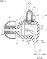
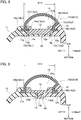
- Fig. 1 is a vertical cross-sectional view illustrating a modeled structure of the earphone 91
- Fig. 2 is an exploded view of the model of the earphone 91 illustrated in Fig. 1
- the earphone 91 described below is a canal-type (earplug-type) earphone, and is to be put in the external ear on the right side.
- the earphone for the left ear has a symmetrical structure with respect to the earphone for the right ear, and the following explanations are made mainly for the earphone 91 for the right ear.
- Fig. 1 indicates the respective directions of the left, the right, the top, and the bottom of the earphone 91 with the corresponding arrows when the earphone 91 is put in the right external ear.
- the front side of the earphone 91 is on the back side of the sheet of Fig. 1
- the rear side of the earphone 91 is on the front side of the sheet of Fig. 1 .
- the earphone 91 includes a first housing 11, a second housing 12, an inner frame 13, a supporter 14, a speaker unit 82, and a cord 83.
- the first housing 11 and the second housing 12 are respectively located on the head side of the user and the opposite side of the head side when the earphone 91 is put in the external ear.
- the first and second housings 11 and 12 are attached together in the right-left direction, which is the first direction, so as to serve as a hollow casing 1K having a space Va therein.
- the speaker unit 82 is housed in the space Va.
- the speaker unit 82 is connected with leads 83a, and a cord 83 enclosing the leads 83a is led out of the space Va through a penetration hole 122 of a cord-leading part 124 projecting from the second housing 12.
- the first housing 11 is provided at the left end with a sound channel part 111 projecting toward the left.
- the inner frame 13 includes a base part 131 having a T-shape and including a narrow neck part 131a, and a projection part 13a projecting in the right-left direction from the lower end of the base part 131.
- a part of the projection part 13a projecting toward the left is defined as a projection part 13a1
- the other part of the projection part 13a projecting toward the right is defined as a projection part 13a2.
- the first housing 11 has a frame engagement hollow 11a to which the projection part 13a1 is fitted to be engaged.
- the second housing 12 has a frame engagement hollow 12a to which the projection part 13a2 is fitted to be engaged.
- the first housing 11, the second housing 12, and the inner frame 13 are formed from hard resin.
- the resin is acrylonitrile butadiene styrene (ABS), for example.
- the supporter 14 has more flexibility than the first housing 11 and the second housing 12.
- the material used for the supporter 14 is silicone rubber, for example.
- the supporter 14 includes a base part 14a having a substantially U-shape and open on the bottom side in the vertical cross-sectional view, and a stretching part 14b stretching outward at the lower end of the open end part of the base part 14a in the right-left direction.
- a part of the stretching part 14b stretching outward toward the left is defined as a first stretching part 14b1
- the other part of the stretching part 14b stretching outward toward the right is defined as a second stretching part 14b2.
- the first housing 11 has a supporter engagement hollow 11b as a first engagement part to which the stretching part 14b1 is fitted to be engaged
- the second housing 12 has a supporter engagement hollow 12b as a second engagement part to which the stretching part 14b2 is fitted to be engaged.
- the earphone 91 is connected to a music reproduction device at the tip of the cord 83 so as to supply voice signals to the speaker unit 82.
- the speaker unit 82 converts the input voice signals to voice so as to output the voice toward the left.
- the output voice is emitted outward from the tip of the ear piece 81 through the inner space of the sound channel part 111.
- the assembly of the earphone 91 starting from the exploded state of the model as illustrated in Fig. 2 is made as follows.
- the inner frame 13 is fitted to the open end part of the supporter 14 such that the neck part 131a of the base part 13 and the projection part 13a are exposed to the outside.
- the inner width of the opening of the supporter 14 is set to be slightly smaller than the outer width of the inner frame 13 in the right-left direction, so that the inner frame 13 is fitted to be supported by the supporter 14 while being prevented from unintentionally being dropped off upon the friction with the supporter 14.
- the leads 83a are then connected and fixed to the speaker unit 82.
- the first housing 11 and the second housing 12 are engaged together while interposing the engaged portion of the supporter 14 and the inner frame 13 supported by the supporter 14, so as to be assembled as in the state illustrated in Fig. 1 .
- the engaged portion is indicated by a boundary part 15.
- the engagement between the first housing 11 and the second housing 12 at the boundary part 15 may be a simple strong engagement between the recess and the projection, may be made via an adhesive, or may be made by welding.
- the supporter 14 is not limited to the hollow member having an inner space V14 as illustrated in Fig. 1 , and may be a member without space therein.
- the outer width D14 of the supporter 14 cannot be reduced if force is applied in the right-left direction to reduce the width D14 so as to intentionally remove the supporter 14, since the inner frame 13 is held at the open end part of the supporter 14 substantially with no gap.
- the inner frame 13 can avoid the reduction in the width D14 of the supporter 14 in the right-left direction.
- Preparing the supporter 14 as an independent member without using any insert molding to assemble the earphone 91 can ensure substantially the same resistance to removal as in the case of the preparation of the supporter 14 obtained by the insert molding.
- any other supporter different from the supporter 14 having different projecting levels and projecting shapes can be used to assemble the earphone 91 with the same inner frame 13 used in common.
- the earphone 91 thus does not need to use a dedicated metal die for the insert molding, regardless of the use of the supporter 14. Therefore, productivity is improved.
- the earphone 91A has a symmetrical structure between the right side and the left side, and the following explanations are made mainly for the earphone 91A for the right ear.
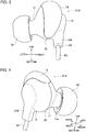
- Fig. 3 illustrates the earphone 91A when put in the right ear as viewed from the back side of the head of the user
- Fig. 4 illustrates the earphone 91A as viewed from the diagonally upper front-right side of the head.
- the earphone 91A includes the first housing 11 and the second housing 12 attached together at the boundary part 15.
- the supporter 14 is held in the region from the diagonally upper front side which is a part of the boundary part 15 in the circumferential direction to the diagonally rear bottom side via the top and back sides.
- This configuration allows the supporter 14 to be in contact with the wide area in the inner wall of the antihelix when the earphone 91A is put in the external ear, so as to achieve a fine feel of fitting of the earphone 91A to the external ear.
- the inner frame 13 (not illustrated but hidden inside the supporter 14) supported by the supporter 14 at the open end part of the supporter 14 is interposed and held between the first housing 11 and the second housing 12.
- the cord 83 is led out of the penetration hole 122 of the cord-leading part 124 in the second housing 12.
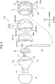
- Fig. 5 is an assembly diagram of the earphone 91A.
- the inner frame 13 has a thin arc-like crescent shape as viewed from the side (for example, from the left).
- the projection part 13a of the inner frame 13 includes the projection parts 13a1 and 13a2 each projecting into a flange on both right and left sides at the middle portion of the arc-like shape in the longitudinal direction (the top-bottom direction).
- the first housing 11 has the frame engagement hollow 11a to which the projection part 13a1 is fitted to be engaged
- the second housing 12 has the frame engagement hollow 12a to which the projection part 13a2 is fitted to be engaged.
- the supporter 14 has an arc-like crescent shape having a greater height than the inner frame 13 as viewed from the side (for example, from the left).
- the supporter 14 has a sac-like shape open on the back side of the sheet of Fig. 5 .
- the stretching part 14b of the supporter 14 includes a set of three stretching parts 14b1 and a set of three stretching parts 14b2 each projecting into a flange on both right and left sides at the middle portion in the longitudinal direction (the top-bottom direction) at the open end part of the supporter 14.
- the supporter 14 is formed like a brim
- the first housing 11 has the supporter engagement hollow 11b to which the stretching part 14b1 is fitted to be engaged
- the second housing 12 has the supporter engagement hollow 12b to which the stretching part 14b2 is fitted to be engaged.
- the earphone 91A can be assembled through the following steps.
- the inner frame 13 is fitted and engaged with the supporter 14 in the direction as indicated by the arrow DRb so as to obtain the engaged part.
- the speaker unit 82 electrically connected with the leads 83a is housed in the first housing 11 in the direction indicated by the arrow DRc.
- the cord 83 on the tip side is caused to pass through to be led out of the penetration hole 122 of the cord-leading part 124 (refers to Fig. 3 ) in the second housing 12, as indicated by the arrow of the chain line DRd.
- the first housing 11 and the second housing 12 are then fitted together so as to interpose the engaged part of the inner frame 13 and the supporter 14.
- the projection part 13a1 of the inner frame 13 is engaged with the frame engagement hollow 11a of the first housing 11, and the stretching part 14b1 of the supporter 14 is engaged with the supporter engagement hollow 11b of the first housing 11.
- the projection part 13a2 of the inner frame 13 is engaged with the frame engagement hollow 12a of the second housing 12, and the stretching part 14b2 of the supporter 14 is engaged with the supporter engagement hollow 12b of the second housing 12.
- the projection parts 13a1 and 13a2 and the frame engagement hollows 11a and 12a are collectively referred to also as a frame engagement part FK.
- the engagement of the frame engagement part FK prevents the movement of the inner frame 13 with respect to the first housing 11 and the second housing 12 at least in the direction perpendicular to the right-left direction.
- the earphone 91A and the earphone 91 as a model of the earphone 91A thus can be assembled easily through the steps as described above. This can also prevent the supporter 14 from being dropped off after the respective earphones 91A and 91 are assembled.
- the respective earphones 91A and 91 can be manufactured while including the supporter 14 serving as a cushion without using insert molding.
- the cost for metal dies to be used can be reduced and the respective constituent components are easy to manufacture, so as to prevent available molding factories from being limited.
- the earphones 91A and 91 thus contribute to the improved productivity.
- the respective earphones 91A and 91 can also be assembled while using the same inner frame 13 but enabling the shape of the supporter to be varied.
- the earphones 91A and 91 thus enable the respective members to be used in common and contribute to the improved productivity accordingly.
- the respective earphones 91A and 91 can also be assembled while using the first housing 11 and the second housing 12 but enabling the shape of either the inner frame 13 or the supporter 14 to be varied.
- the earphones 91A and 91 thus have the advantage of the improved productivity in view of the components to be used in common.
- the present embodiment thus can achieve the effect of contributing to the improved productivity while including the flexible supporter to be in contact with the external ear.
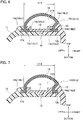
- the structure of the supporter 14 to be fitted to the first housing 11 and the second housing 12 is not limited to that described above, and may be modified as illustrated in the following modified examples 1 to 5 with reference to Fig. 6 to Fig. 10 .
- the respective supporter attachment structures TK1 to TK5 illustrated in Fig. 6 to Fig. 10 can be substituted for the supporter attachment structure TK indicated in the area with reference sign A in Fig. 1 .
- the earphones of the modified examples 1 to 5 obtained such that the supporter attachment structure TK of the earphone 91 is replaced with the respective supporter attachment structures TK1 to TK5, are referred to below as earphones 911 to 915.
- the supporter attachment structure TK1 of the earphone 911 of the modified example 1 differs from the supporter attachment structure TK in not including the engaged portion between the inner frame 13 and the first housing 11 or the second housing 12, and in that the supporter 14 is provided with a part interposed between the inner frame 13 and the respective first and second housings 11 and 12.
- the supporter 14 includes the stretching part 14b1 engaged with the first housing 11 and the stretching part 14b2 engaged with the second housing 12, as in the case of the supporter attachment structure TK.
- the supporter 14 further includes an inner stretching part 14c including inner stretching parts 14c1 and 14c2 respectively engaged with inner engagement parts 13c1 and 13c2 provided as an inner engagement part 13c in the inner frame 13.
- the supporter attachment structure TK1 does not allow the width D14 of the supporter 14 to be reduced if the supporter 14 is attempted to be removed, since the inner frame 13 is held at the open end part of the supporter 14 with substantially no gap. This can prevent the supporter 14 from being dropped out of the main body 1 after the earphone 911 is assembled.
- the boundary part 15 is defined to be provided with a step at which the first housing 11 and the second housing 12 are engaged together.
- the inner frame 13 may be fixed to the first housing 11 or the second housing 12 by adhesion or welding so as to be integrated together more firmly.
- the supporter attachment structure TK2 of the earphone 912 of the modified example 2 differs from the supporter attachment structure TK in not including the engaged portion between the inner frame 13 and the first housing 11 or the second housing 12.
- the supporter attachment structure TK2 does not allow the width D14 of the supporter 14 to be reduced if the supporter 14 is attempted to be removed, since the inner frame 13 is held at the open end part of the supporter 14 with substantially no gap. This can prevent the supporter 14 from being dropped out of the main body 1 after the earphone 912 is assembled.
- the boundary part 15 is defined to be provided with a step at which the first housing 11 and the second housing 12 are engaged together.
- the inner frame 13 may be fixed to the first housing 11 or the second housing 12 by adhesion or welding so as to be integrated together more firmly.
- the supporter attachment structure TK3 of the earphone 913 of the modified example 3 differs from the supporter attachment structure TK in that the supporter 14 is provided with a part interposed between the inner frame 13 and the respective first and second housings 11 and 12.
- the supporter 14 includes an inner stretching part 14c including an inner stretching part 14c1 interposed between the inner frame 13 and the first housing 11, and an inner stretching part 14c2 interposed between the inner frame 13 and the second housing 12.
- the supporter attachment structure TK3 does not allow the width D14 of the supporter 14 to be reduced if the supporter 14 is attempted to be removed, since the inner frame 13 is held at the open end part of the supporter 14 with substantially no gap. This can prevent the supporter 14 from being dropped out of the main body 1 after the earphone 913 is assembled.
- the boundary part 15 is configured such that the first housing 11 and the second housing 12 are simply in contact with each other with no step required, since the engaged part between the first housing 11 and the second housing 12 in the thickness direction is defined by the inner frame 13.
- the supporter attachment structure TK4 of the earphone 914 of the modified example 4 differs from the supporter attachment structure TK in that the engaged part of the inner frame 13 with the first housing 11 and the second housing 12 projects toward the space Va.
- the inner frame 13 includes a T-shaped projection part 13d projecting downward, as illustrated in Fig 9 .
- the neck part of the T-shaped projection part 13d has a housing recessed part 13d1 which is a recess to which the edge of the first housing 11 is fitted to be engaged, and has a housing recessed part 13d2 which is a recess to which the edge of the second housing 12 is fitted to be engaged.
- the tip part of the T-shaped projection part 13d projects toward the space Va.
- the supporter attachment structure TK4 does not allow the width D14 of the supporter 14 to be reduced if the supporter 14 is attempted to be removed, since the inner frame 13 is held at the open end part of the supporter 14 with substantially no gap. This can prevent the supporter 14 from being dropped out of the main body 1 after the earphone 914 is assembled.
- the engaged part between the first housing 11 and the second housing 12 in the thickness direction is defined by the T-shaped projection part 13d of the inner frame 13, while the projected part is present in the space Va. Since the space Va serves as a back cavity of the speaker unit 82, the projected part may have an influence on the reproduced sound of the earphone 914, which may have reproduction characteristics different from the other supporter attachment structures TK1 to TK3 without being provided with the projected part in the space Va, in view of the airtight properties of the back cavity.
- the supporter attachment structure TK5 of the earphone 915 of the modified example 5 differs from the supporter attachment structure TK in that the supporter 14 and the first and second housings 11 and 12 are engaged together and positioned by the inner frame 13.
- the inner frame 13 is provided with a dowel 13e including a dowel 13e1 and a dowel 13e2 each projecting in the right-left direction.
- the supporter 14 has a dowel hole 14d1 and a dowel hole 14d2 through which the dowel 13e1 and the dowel 13e2 respectively penetrate.
- the first housing 11 and the second housing 12 have dowel hollows 11d and 12d to which the dowel 13e1 and the dowel 13e2 can be fitted to be engaged.
- the dowel 13e1 and the dowel 13e2 of the inner frame 13 are caused to be inserted to the dowel hole 14d1 and the dowel hole 14d2 of the supporter 14.
- the dowel 13e1 and the dowel 13e2 which each have a sufficient length to project, are engaged with the dowel hollow 11d of the first housing 11 and the dowel hollow 12d of the second housing 12 so that the first housing 11 and the second housing 12 are attached together.
- the supporter attachment structure TK5 does not allow the width D14 of the supporter 14 to be reduced if the supporter 14 is attempted to be removed, since the inner frame 13 is held at the open end part of the supporter 14 with substantially no gap. This can prevent the supporter 14 from being dropped out of the main body 1 after the earphone 915 is assembled.
- the frame engagement part FK corresponds to the part including the dowels 13e1 and 13e2 of the inner frame 13 and the dowel hollow 11d of the first housing 11 and the dowel hollow 12d of the second housing 12 in the supporter attachment structure TK5.
- the engagement of the frame engagement part FK in the supporter attachment structure TK5 also suppresses the movement of the inner frame 13 with respect to the first housing 11 and the second housing 12 at least in the direction perpendicular to the right-left direction.
- the inner frame 13, the supporter 14, and the respective first and second housings 11 and 12 are positioned by the single dowel 13e.
- This configuration can reduce the dimensions in the upper-lower direction in Fig. 10 , so as to facilitate a reduction in size of the earphone 915.
- the respective earphones 911 to 915 having the respective supporter attachment structures TK1 to TK5 of the modified examples 1 to 5 can be manufactured while including the supporter 14 serving as a cushion without using insert molding. This can reduce the cost of metal dies to be used to prevent molding factories from being limited. The earphones 911 to 915 contribute to the improved productivity accordingly.
- the respective earphones 911 to 915 can also be assembled while using the same inner frame 13 but enabling the shape of the supporter to be varied.
- the earphones 911 to 915 thus have the advantage of the improved productivity in view of the components to be used in common.
- the earphone 91 is not limited to the canal type in which the ear piece 81 is inserted into the external auditory meatus.
- the earphone 91 may be an in-ear type in which the main body 1 without including the sound channel part 111 is fitted to the external ear.
- the earphones 91, 91A, and 911 to 915 are fitted to the outer ear of the user such that the supporter 14 is brought into contact with the inner wall of the outer ear when the casing 1K is put in the concha.
- the inner wall of the outer ear is the inner wall of the antihelix, for example.
- the supporter 14 is typically slightly contracted in the put state, and presses the inner wall by the elastic repulsive force, so as to keep the stable fitted state while the user can ensure a fine feel of fitting.
- the supporter 14 is not limited to that to be in contact with the inner wall of the antihelix, and may be brought into contact with the inner wall of any other part of the outer ear.
Landscapes
- Engineering & Computer Science (AREA)
- Physics & Mathematics (AREA)
- Acoustics & Sound (AREA)
- Signal Processing (AREA)
- Health & Medical Sciences (AREA)
- Otolaryngology (AREA)
- Manufacturing & Machinery (AREA)
- Headphones And Earphones (AREA)
Abstract
Description
- The present disclosure relates to earphones.
- Earphones are known that include a body part to be put in the external ear, and a projection part (a supporter) projecting from the body part, as disclosed in Japanese Patent Application Publication No.
2009-060157 - The body part is preferably formed from hard resin, and the supporter is preferably formed from silicone rubber having flexibility. A housing serving as an outer frame of the body part and the supporter are thus typically integrally formed by insert molding.
- The insert molding limits molding factories enabling the molding while ensuring high quality, since metal dies are typically expensive and require a high molding technique. If variations in shape of either the body part or the supporter are required to provide several types of earphones, a dedicated metal die for each shape needs to be prepared, which impedes constituent components from being used in common.
- The conventional earphones as described above including the flexible supporter in contact with the external ear thus still have a problem with the insert molding in order to improve productivity.
- An object of one or more embodiments is to provide earphones contributing to achieving high productivity while including flexible supporters.
- One or more embodiments provide an earphone including a first housing and a second housing attached together in a first direction to compose a casing having a space therein, a speaker unit housed in the space, a supporter interposed and held between the first housing and the second housing and having more flexibility than the first housing and the second housing, and an inner frame preventing a reduction in width of the supporter in the first direction.
-
-
Fig. 1 is a vertically cross-sectional view illustrating a modeled structure of anearphone 91 as an example of an earphone according to one or more embodiments. -
Fig. 2 is an exploded view ofFig. 1 . -
Fig. 3 is a first external perspective view of anearphone 91A. -
Fig. 4 is a second external perspective view of theearphone 91A. -
Fig. 5 is an assembly diagram of theearphone 91A to be assembled. -
Fig. 6 is a partly cross-sectional view illustrating a supporter attachment structure TK1 as modified example 1 of a supporter attachment structure TK. -
Fig. 7 is a partly cross-sectional view illustrating a supporter attachment structure TK2 as modified example 2 of the supporter attachment structure TK. -
Fig. 8 is a partly cross-sectional view illustrating a supporter attachment structure TK3 as modified example 3 of the supporter attachment structure TK. -
Fig. 9 is a partly cross-sectional view illustrating a supporter attachment structure TK4 as modified example 4 of the supporter attachment structure TK. -
Fig. 10 is a partly cross-sectional view illustrating a supporter attachment structure TK5 as modified example 5 of the supporter attachment structure TK. - One or more embodiments will be illustrated below with
earphones -
Fig. 1 is a vertical cross-sectional view illustrating a modeled structure of theearphone 91, andFig. 2 is an exploded view of the model of theearphone 91 illustrated inFig. 1 . Theearphone 91 described below is a canal-type (earplug-type) earphone, and is to be put in the external ear on the right side. The earphone for the left ear has a symmetrical structure with respect to the earphone for the right ear, and the following explanations are made mainly for theearphone 91 for the right ear. -
Fig. 1 indicates the respective directions of the left, the right, the top, and the bottom of theearphone 91 with the corresponding arrows when theearphone 91 is put in the right external ear. The front side of theearphone 91 is on the back side of the sheet ofFig. 1 , and the rear side of theearphone 91 is on the front side of the sheet ofFig. 1 . - The
earphone 91 includes afirst housing 11, asecond housing 12, aninner frame 13, asupporter 14, aspeaker unit 82, and acord 83. - The
first housing 11 and thesecond housing 12 are respectively located on the head side of the user and the opposite side of the head side when theearphone 91 is put in the external ear. The first andsecond housings hollow casing 1K having a space Va therein. - The
speaker unit 82 is housed in the space Va. Thespeaker unit 82 is connected withleads 83a, and acord 83 enclosing theleads 83a is led out of the space Va through apenetration hole 122 of a cord-leadingpart 124 projecting from thesecond housing 12. - The
first housing 11 is provided at the left end with asound channel part 111 projecting toward the left. Anear piece 81 to be inserted into the external auditory meatus of the user when theearphone 91 is used, is removably attached to thesound channel part 111. - The
inner frame 13 includes abase part 131 having a T-shape and including anarrow neck part 131a, and aprojection part 13a projecting in the right-left direction from the lower end of thebase part 131. A part of theprojection part 13a projecting toward the left is defined as a projection part 13a1, and the other part of theprojection part 13a projecting toward the right is defined as a projection part 13a2. - The
first housing 11 has a frame engagement hollow 11a to which the projection part 13a1 is fitted to be engaged. Thesecond housing 12 has a frame engagement hollow 12a to which the projection part 13a2 is fitted to be engaged. - The
first housing 11, thesecond housing 12, and theinner frame 13 are formed from hard resin. The resin is acrylonitrile butadiene styrene (ABS), for example. - The
supporter 14 has more flexibility than thefirst housing 11 and thesecond housing 12. The material used for thesupporter 14 is silicone rubber, for example. - As illustrated in
Fig. 1 andFig. 2 , thesupporter 14 includes abase part 14a having a substantially U-shape and open on the bottom side in the vertical cross-sectional view, and a stretchingpart 14b stretching outward at the lower end of the open end part of thebase part 14a in the right-left direction. A part of the stretchingpart 14b stretching outward toward the left is defined as a first stretching part 14b1, and the other part of the stretchingpart 14b stretching outward toward the right is defined as a second stretching part 14b2. - The
first housing 11 has a supporter engagement hollow 11b as a first engagement part to which the stretching part 14b1 is fitted to be engaged, and thesecond housing 12 has a supporter engagement hollow 12b as a second engagement part to which the stretching part 14b2 is fitted to be engaged. - The
earphone 91 is connected to a music reproduction device at the tip of thecord 83 so as to supply voice signals to thespeaker unit 82. Thespeaker unit 82 converts the input voice signals to voice so as to output the voice toward the left. The output voice is emitted outward from the tip of theear piece 81 through the inner space of thesound channel part 111. - The assembly of the
earphone 91 starting from the exploded state of the model as illustrated inFig. 2 is made as follows. - First, as indicated by the arrow DRa in
Fig. 2 , theinner frame 13 is fitted to the open end part of thesupporter 14 such that theneck part 131a of thebase part 13 and theprojection part 13a are exposed to the outside. - The inner width of the opening of the
supporter 14 is set to be slightly smaller than the outer width of theinner frame 13 in the right-left direction, so that theinner frame 13 is fitted to be supported by thesupporter 14 while being prevented from unintentionally being dropped off upon the friction with thesupporter 14. - The
leads 83a are then connected and fixed to thespeaker unit 82. Thefirst housing 11 and thesecond housing 12 are engaged together while interposing the engaged portion of thesupporter 14 and theinner frame 13 supported by thesupporter 14, so as to be assembled as in the state illustrated inFig. 1 . The engaged portion is indicated by aboundary part 15. - The engagement between the
first housing 11 and thesecond housing 12 at theboundary part 15 may be a simple strong engagement between the recess and the projection, may be made via an adhesive, or may be made by welding. - The
supporter 14 is not limited to the hollow member having an inner space V14 as illustrated inFig. 1 , and may be a member without space therein. - As illustrated in
Fig. 1 , the outer width D14 of thesupporter 14 cannot be reduced if force is applied in the right-left direction to reduce the width D14 so as to intentionally remove thesupporter 14, since theinner frame 13 is held at the open end part of thesupporter 14 substantially with no gap. - Namely, the
inner frame 13 can avoid the reduction in the width D14 of thesupporter 14 in the right-left direction. - This can prevent the
supporter 14 from coming out of themain body 1 during normal use. - Preparing the
supporter 14 as an independent member without using any insert molding to assemble theearphone 91 can ensure substantially the same resistance to removal as in the case of the preparation of thesupporter 14 obtained by the insert molding. - Since the
inner frame 13 is arranged at the open end part of thesupporter 14 with almost no gap, any other supporter different from thesupporter 14 having different projecting levels and projecting shapes can be used to assemble theearphone 91 with the sameinner frame 13 used in common. - The
earphone 91 thus does not need to use a dedicated metal die for the insert molding, regardless of the use of thesupporter 14. Therefore, productivity is improved. - An example of the above modeled structure used for a commercial earphone is described below with reference to the
earphone 91A as illustrated inFig. 3 to Fig. 5 . Theearphone 91A has a symmetrical structure between the right side and the left side, and the following explanations are made mainly for theearphone 91A for the right ear. -
Fig. 3 illustrates theearphone 91A when put in the right ear as viewed from the back side of the head of the user, andFig. 4 illustrates theearphone 91A as viewed from the diagonally upper front-right side of the head. - The
earphone 91A includes thefirst housing 11 and thesecond housing 12 attached together at theboundary part 15. Thesupporter 14 is held in the region from the diagonally upper front side which is a part of theboundary part 15 in the circumferential direction to the diagonally rear bottom side via the top and back sides. - This configuration allows the
supporter 14 to be in contact with the wide area in the inner wall of the antihelix when theearphone 91A is put in the external ear, so as to achieve a fine feel of fitting of theearphone 91A to the external ear. - The inner frame 13 (not illustrated but hidden inside the supporter 14) supported by the
supporter 14 at the open end part of thesupporter 14 is interposed and held between thefirst housing 11 and thesecond housing 12. - The
cord 83 is led out of thepenetration hole 122 of the cord-leadingpart 124 in thesecond housing 12. -
Fig. 5 is an assembly diagram of theearphone 91A. - The
inner frame 13 has a thin arc-like crescent shape as viewed from the side (for example, from the left). Theprojection part 13a of theinner frame 13 includes the projection parts 13a1 and 13a2 each projecting into a flange on both right and left sides at the middle portion of the arc-like shape in the longitudinal direction (the top-bottom direction). - The
first housing 11 has the frame engagement hollow 11a to which the projection part 13a1 is fitted to be engaged, and thesecond housing 12 has the frame engagement hollow 12a to which the projection part 13a2 is fitted to be engaged. - The
supporter 14 has an arc-like crescent shape having a greater height than theinner frame 13 as viewed from the side (for example, from the left). Thesupporter 14 has a sac-like shape open on the back side of the sheet ofFig. 5 . - The stretching
part 14b of thesupporter 14 includes a set of three stretching parts 14b1 and a set of three stretching parts 14b2 each projecting into a flange on both right and left sides at the middle portion in the longitudinal direction (the top-bottom direction) at the open end part of thesupporter 14. Thesupporter 14 is formed like a brim - The
first housing 11 has the supporter engagement hollow 11b to which the stretching part 14b1 is fitted to be engaged, and thesecond housing 12 has the supporter engagement hollow 12b to which the stretching part 14b2 is fitted to be engaged. - The
earphone 91A can be assembled through the following steps. - First, the
inner frame 13 is fitted and engaged with thesupporter 14 in the direction as indicated by the arrow DRb so as to obtain the engaged part. - The
speaker unit 82 electrically connected with theleads 83a is housed in thefirst housing 11 in the direction indicated by the arrow DRc. Thecord 83 on the tip side is caused to pass through to be led out of thepenetration hole 122 of the cord-leading part 124 (refers toFig. 3 ) in thesecond housing 12, as indicated by the arrow of the chain line DRd. - The
first housing 11 and thesecond housing 12 are then fitted together so as to interpose the engaged part of theinner frame 13 and thesupporter 14. - At the same time, the projection part 13a1 of the
inner frame 13 is engaged with the frame engagement hollow 11a of thefirst housing 11, and the stretching part 14b1 of thesupporter 14 is engaged with the supporter engagement hollow 11b of thefirst housing 11. - The projection part 13a2 of the
inner frame 13 is engaged with the frame engagement hollow 12a of thesecond housing 12, and the stretching part 14b2 of thesupporter 14 is engaged with the supporter engagement hollow 12b of thesecond housing 12. - The projection parts 13a1 and 13a2 and the frame engagement hollows 11a and 12a are collectively referred to also as a frame engagement part FK. The engagement of the frame engagement part FK prevents the movement of the
inner frame 13 with respect to thefirst housing 11 and thesecond housing 12 at least in the direction perpendicular to the right-left direction. - The
earphone 91A and theearphone 91 as a model of theearphone 91A thus can be assembled easily through the steps as described above. This can also prevent thesupporter 14 from being dropped off after therespective earphones - The
respective earphones supporter 14 serving as a cushion without using insert molding. - The cost for metal dies to be used can be reduced and the respective constituent components are easy to manufacture, so as to prevent available molding factories from being limited. The
earphones - The
respective earphones inner frame 13 but enabling the shape of the supporter to be varied. Theearphones - The
respective earphones first housing 11 and thesecond housing 12 but enabling the shape of either theinner frame 13 or thesupporter 14 to be varied. Theearphones - The present embodiment thus can achieve the effect of contributing to the improved productivity while including the flexible supporter to be in contact with the external ear.
- The above example is not limited to the configurations as described above, and may be modified as appropriate without departing from the scope of the present embodiment.
- The structure of the
supporter 14 to be fitted to thefirst housing 11 and thesecond housing 12 is not limited to that described above, and may be modified as illustrated in the following modified examples 1 to 5 with reference toFig. 6 to Fig. 10 . - The respective supporter attachment structures TK1 to TK5 illustrated in
Fig. 6 to Fig. 10 can be substituted for the supporter attachment structure TK indicated in the area with reference sign A inFig. 1 . The earphones of the modified examples 1 to 5 obtained such that the supporter attachment structure TK of theearphone 91 is replaced with the respective supporter attachment structures TK1 to TK5, are referred to below asearphones 911 to 915. - As illustrated in
Fig. 6 , the supporter attachment structure TK1 of theearphone 911 of the modified example 1 differs from the supporter attachment structure TK in not including the engaged portion between theinner frame 13 and thefirst housing 11 or thesecond housing 12, and in that thesupporter 14 is provided with a part interposed between theinner frame 13 and the respective first andsecond housings - In particular, the
supporter 14 includes the stretching part 14b1 engaged with thefirst housing 11 and the stretching part 14b2 engaged with thesecond housing 12, as in the case of the supporter attachment structure TK. Thesupporter 14 further includes aninner stretching part 14c including inner stretching parts 14c1 and 14c2 respectively engaged with inner engagement parts 13c1 and 13c2 provided as aninner engagement part 13c in theinner frame 13. - The supporter attachment structure TK1 does not allow the width D14 of the
supporter 14 to be reduced if thesupporter 14 is attempted to be removed, since theinner frame 13 is held at the open end part of thesupporter 14 with substantially no gap. This can prevent thesupporter 14 from being dropped out of themain body 1 after theearphone 911 is assembled. - According to the supporter attachment structure TK1, since the
inner frame 13 is not engaged with thefirst housing 11 or thesecond housing 12, theboundary part 15 is defined to be provided with a step at which thefirst housing 11 and thesecond housing 12 are engaged together. - The
inner frame 13 may be fixed to thefirst housing 11 or thesecond housing 12 by adhesion or welding so as to be integrated together more firmly. - As illustrated in
Fig. 7 , the supporter attachment structure TK2 of theearphone 912 of the modified example 2 differs from the supporter attachment structure TK in not including the engaged portion between theinner frame 13 and thefirst housing 11 or thesecond housing 12. - The supporter attachment structure TK2 does not allow the width D14 of the
supporter 14 to be reduced if thesupporter 14 is attempted to be removed, since theinner frame 13 is held at the open end part of thesupporter 14 with substantially no gap. This can prevent thesupporter 14 from being dropped out of themain body 1 after theearphone 912 is assembled. - According to the supporter attachment structure TK2, since the
inner frame 13 is not engaged with thefirst housing 11 or thesecond housing 12, theboundary part 15 is defined to be provided with a step at which thefirst housing 11 and thesecond housing 12 are engaged together. - The
inner frame 13 may be fixed to thefirst housing 11 or thesecond housing 12 by adhesion or welding so as to be integrated together more firmly. - As illustrated in
Fig. 8 , the supporter attachment structure TK3 of theearphone 913 of the modified example 3 differs from the supporter attachment structure TK in that thesupporter 14 is provided with a part interposed between theinner frame 13 and the respective first andsecond housings - In particular, the
supporter 14 includes aninner stretching part 14c including an inner stretching part 14c1 interposed between theinner frame 13 and thefirst housing 11, and an inner stretching part 14c2 interposed between theinner frame 13 and thesecond housing 12. - The supporter attachment structure TK3 does not allow the width D14 of the
supporter 14 to be reduced if thesupporter 14 is attempted to be removed, since theinner frame 13 is held at the open end part of thesupporter 14 with substantially no gap. This can prevent thesupporter 14 from being dropped out of themain body 1 after theearphone 913 is assembled. - According to the supporter attachment structure TK3, the
boundary part 15 is configured such that thefirst housing 11 and thesecond housing 12 are simply in contact with each other with no step required, since the engaged part between thefirst housing 11 and thesecond housing 12 in the thickness direction is defined by theinner frame 13. - As illustrated in
Fig. 9 , the supporter attachment structure TK4 of theearphone 914 of the modified example 4 differs from the supporter attachment structure TK in that the engaged part of theinner frame 13 with thefirst housing 11 and thesecond housing 12 projects toward the space Va. - In particular, the
inner frame 13 includes a T-shapedprojection part 13d projecting downward, as illustrated inFig 9 . - The neck part of the T-shaped
projection part 13d has a housing recessed part 13d1 which is a recess to which the edge of thefirst housing 11 is fitted to be engaged, and has a housing recessed part 13d2 which is a recess to which the edge of thesecond housing 12 is fitted to be engaged. The tip part of the T-shapedprojection part 13d projects toward the space Va. - The supporter attachment structure TK4 does not allow the width D14 of the
supporter 14 to be reduced if thesupporter 14 is attempted to be removed, since theinner frame 13 is held at the open end part of thesupporter 14 with substantially no gap. This can prevent thesupporter 14 from being dropped out of themain body 1 after theearphone 914 is assembled. - According to the supporter attachment structure TK4, the engaged part between the
first housing 11 and thesecond housing 12 in the thickness direction is defined by the T-shapedprojection part 13d of theinner frame 13, while the projected part is present in the space Va. Since the space Va serves as a back cavity of thespeaker unit 82, the projected part may have an influence on the reproduced sound of theearphone 914, which may have reproduction characteristics different from the other supporter attachment structures TK1 to TK3 without being provided with the projected part in the space Va, in view of the airtight properties of the back cavity. - As illustrated in
Fig. 10 , the supporter attachment structure TK5 of theearphone 915 of the modified example 5 differs from the supporter attachment structure TK in that thesupporter 14 and the first andsecond housings inner frame 13. - In particular, the
inner frame 13 is provided with adowel 13e including a dowel 13e1 and a dowel 13e2 each projecting in the right-left direction. - The
supporter 14 has a dowel hole 14d1 and a dowel hole 14d2 through which the dowel 13e1 and the dowel 13e2 respectively penetrate. - The
first housing 11 and thesecond housing 12 havedowel hollows - During the assembling process, the dowel 13e1 and the dowel 13e2 of the
inner frame 13 are caused to be inserted to the dowel hole 14d1 and the dowel hole 14d2 of thesupporter 14. The dowel 13e1 and the dowel 13e2, which each have a sufficient length to project, are engaged with the dowel hollow 11d of thefirst housing 11 and the dowel hollow 12d of thesecond housing 12 so that thefirst housing 11 and thesecond housing 12 are attached together. - The supporter attachment structure TK5 does not allow the width D14 of the
supporter 14 to be reduced if thesupporter 14 is attempted to be removed, since theinner frame 13 is held at the open end part of thesupporter 14 with substantially no gap. This can prevent thesupporter 14 from being dropped out of themain body 1 after theearphone 915 is assembled. - The frame engagement part FK corresponds to the part including the dowels 13e1 and 13e2 of the
inner frame 13 and the dowel hollow 11d of thefirst housing 11 and the dowel hollow 12d of thesecond housing 12 in the supporter attachment structure TK5. The engagement of the frame engagement part FK in the supporter attachment structure TK5 also suppresses the movement of theinner frame 13 with respect to thefirst housing 11 and thesecond housing 12 at least in the direction perpendicular to the right-left direction. - According to the supporter attachment structure TK5, the
inner frame 13, thesupporter 14, and the respective first andsecond housings single dowel 13e. This configuration can reduce the dimensions in the upper-lower direction inFig. 10 , so as to facilitate a reduction in size of theearphone 915. - The
respective earphones 911 to 915 having the respective supporter attachment structures TK1 to TK5 of the modified examples 1 to 5 can be manufactured while including thesupporter 14 serving as a cushion without using insert molding. This can reduce the cost of metal dies to be used to prevent molding factories from being limited. Theearphones 911 to 915 contribute to the improved productivity accordingly. - The
respective earphones 911 to 915 can also be assembled while using the sameinner frame 13 but enabling the shape of the supporter to be varied. Theearphones 911 to 915 thus have the advantage of the improved productivity in view of the components to be used in common. - The modified examples 1 to 5 can be combined as appropriate within the available scope of the present embodiment.
- The
earphone 91 is not limited to the canal type in which theear piece 81 is inserted into the external auditory meatus. Theearphone 91 may be an in-ear type in which themain body 1 without including thesound channel part 111 is fitted to the external ear. - The
earphones supporter 14 is brought into contact with the inner wall of the outer ear when thecasing 1K is put in the concha. The inner wall of the outer ear is the inner wall of the antihelix, for example. - The
supporter 14 is typically slightly contracted in the put state, and presses the inner wall by the elastic repulsive force, so as to keep the stable fitted state while the user can ensure a fine feel of fitting. - The
supporter 14 is not limited to that to be in contact with the inner wall of the antihelix, and may be brought into contact with the inner wall of any other part of the outer ear.
Claims (8)
- An earphone comprising:a first housing (11) and a second housing (12) attached together in a first direction to compose a casing (1K) having a space (Va) therein;a speaker unit (82) housed in the space (Va);a supporter (14) interposed and held between the first housing (11) and the second housing (12) and having more flexibility than the first housing (11) and the second housing (12); andan inner frame (13) preventing a reduction in width of the supporter (14) in the first direction.
- The earphone according to claim 1, wherein:the supporter (14) includes a first stretching part (14b1) stretching outward on one side in the first direction and a second stretching part (14b2) stretching outward on another side in the first direction; andthe first housing (11) includes a first engagement part (11b) engaged with the first stretching part (14b1) and a second engagement part (12b) engaged with the second stretching part (14b2).
- The earphone according to claim 1, wherein:the supporter (14) includes a first stretching part (14b1) stretching outward on one side in the first direction and a second stretching part (14b2) stretching outward on another side in the first direction, and a first inner stretching part (14c1) stretching inward on the one side in the first direction and a second inner stretching part (14c2) stretching inward on the other side in the first direction;the first housing (11) includes a first engagement part (11b) engaged with the first stretching part (14b1) and the second housing (12) includes a second engagement part (12b) engaged with the second stretching part (14b2); andthe inner frame (13) includes a first inner engagement part (13c1) engaged with the first inner stretching part (14c1) and a second inner engagement part (13c2) engaged with the second inner stretching part (14c2).
- The earphone according to claim 1, wherein:the supporter (14) includes a first stretching part (14b1) stretching outward on one side in the first direction and a second stretching part (14b2) stretching outward on another side in the first direction;the first housing (11) includes a first engagement part (11b) engaged with the first stretching part (14b1) and the second housing (12) includes a second engagement part (12b) engaged with the second stretching part (14b2); andthe inner frame (13) includes a T-shaped projection part (13d) projecting into the space (Va), a neck part of the T-shaped projection part (13d) has a first housing recessed part (13d1) which is a recess to which an edge of the first housing (11) is fitted to be engaged and a second housing recessed part (13d2) which is a recess to which an edge of the second housing (12) is fitted to be engaged.
- The earphone according to claim 1, wherein:the inner frame (13) includes a first dowel (13e1) projecting outward on one side in the first direction and a second dowel (13e2) projecting outward on another side in the first direction;the supporter (14) has a first dowel hole (14d1) through which the first dowel (13e1) penetrates and a second dowel hole (14d2) through which the second dowel (13e2) penetrates; andthe first housing (11) has a first dowel hollow (11d) to which the first dowel (13e1) is fitted to be engaged, and the second housing (12) has a second dowel hollow (12d) to which the second dowel (13e2) is fitted to be engaged.
- The earphone according to any one of claims 1 to 5, further comprising a frame engagement part (FK) preventing a movement of the inner frame (13) with respect to the first housing (11) and the second housing (12) in a direction perpendicular to the first direction.
- The earphone according to any one of claims 1 to 6, wherein the housing (1K) is put in a concha of an outer ear, and the supporter (14) is brought into contact with an inner wall of the outer ear so as to be fitted to the outer ear.
- The earphone according to claim 7, wherein the inner wall is an inner wall of an antihelix.
Applications Claiming Priority (1)
| Application Number | Priority Date | Filing Date | Title |
|---|---|---|---|
| JP2019206900A JP7434821B2 (en) | 2019-11-15 | 2019-11-15 | earphone |
Publications (2)
| Publication Number | Publication Date |
|---|---|
| EP3823300A1 true EP3823300A1 (en) | 2021-05-19 |
| EP3823300B1 EP3823300B1 (en) | 2022-11-30 |
Family
ID=73343974
Family Applications (1)
| Application Number | Title | Priority Date | Filing Date |
|---|---|---|---|
| EP20207025.6A Active EP3823300B1 (en) | 2019-11-15 | 2020-11-11 | Earphone having supporting member for outer ear |
Country Status (3)
| Country | Link |
|---|---|
| EP (1) | EP3823300B1 (en) |
| JP (2) | JP7434821B2 (en) |
| CN (1) | CN112822581B (en) |
Cited By (1)
| Publication number | Priority date | Publication date | Assignee | Title |
|---|---|---|---|---|
| CN113496630A (en) * | 2021-05-28 | 2021-10-12 | 广东白云学院 | English listening comprehension trainer |
Families Citing this family (1)
| Publication number | Priority date | Publication date | Assignee | Title |
|---|---|---|---|---|
| CN115988396A (en) * | 2023-01-31 | 2023-04-18 | 杭州听世界助听科技有限公司 | A strong adaptability in-ear hearing aid and its wearing method |
Citations (3)
| Publication number | Priority date | Publication date | Assignee | Title |
|---|---|---|---|---|
| US20090041284A1 (en) * | 2007-08-08 | 2009-02-12 | Victor Company Of Japan, Ltd. | Headphone set and method of producing the same |
| JP2009060157A (en) | 2007-08-08 | 2009-03-19 | Victor Co Of Japan Ltd | Method of manufacturing headphone |
| KR101851740B1 (en) * | 2017-04-10 | 2018-04-24 | 에스텍 주식회사 | Earphone with improved wear sensation |
Family Cites Families (8)
| Publication number | Priority date | Publication date | Assignee | Title |
|---|---|---|---|---|
| JP4088841B2 (en) * | 2005-01-19 | 2008-05-21 | 株式会社オーディオテクニカ | Inner earphone |
| JP5256852B2 (en) | 2008-05-30 | 2013-08-07 | 株式会社Jvcケンウッド | headphone |
| JP5024186B2 (en) * | 2008-05-30 | 2012-09-12 | 株式会社Jvcケンウッド | headphone |
| WO2010004624A1 (en) | 2008-07-09 | 2010-01-14 | パイオニア株式会社 | Earphone |
| JP5849480B2 (en) * | 2011-07-13 | 2016-01-27 | 株式会社Jvcケンウッド | earphone |
| JP6330649B2 (en) | 2014-12-19 | 2018-05-30 | 株式会社Jvcケンウッド | Earphone with microphone |
| JP2017158045A (en) | 2016-03-02 | 2017-09-07 | 株式会社オーディオテクニカ | headphone |
| KR101762142B1 (en) * | 2016-03-07 | 2017-08-04 | 한승관 | The ear-wing |
-
2019
- 2019-11-15 JP JP2019206900A patent/JP7434821B2/en active Active
-
2020
- 2020-11-03 CN CN202011210151.1A patent/CN112822581B/en active Active
- 2020-11-11 EP EP20207025.6A patent/EP3823300B1/en active Active
-
2023
- 2023-10-06 JP JP2023174283A patent/JP7619415B2/en active Active
Patent Citations (3)
| Publication number | Priority date | Publication date | Assignee | Title |
|---|---|---|---|---|
| US20090041284A1 (en) * | 2007-08-08 | 2009-02-12 | Victor Company Of Japan, Ltd. | Headphone set and method of producing the same |
| JP2009060157A (en) | 2007-08-08 | 2009-03-19 | Victor Co Of Japan Ltd | Method of manufacturing headphone |
| KR101851740B1 (en) * | 2017-04-10 | 2018-04-24 | 에스텍 주식회사 | Earphone with improved wear sensation |
Cited By (2)
| Publication number | Priority date | Publication date | Assignee | Title |
|---|---|---|---|---|
| CN113496630A (en) * | 2021-05-28 | 2021-10-12 | 广东白云学院 | English listening comprehension trainer |
| CN113496630B (en) * | 2021-05-28 | 2022-12-06 | 广东白云学院 | English listening comprehension trainer |
Also Published As
| Publication number | Publication date |
|---|---|
| JP2021082881A (en) | 2021-05-27 |
| JP2023175954A (en) | 2023-12-12 |
| EP3823300B1 (en) | 2022-11-30 |
| JP7434821B2 (en) | 2024-02-21 |
| CN112822581A (en) | 2021-05-18 |
| JP7619415B2 (en) | 2025-01-22 |
| CN112822581B (en) | 2023-07-04 |
Similar Documents
| Publication | Publication Date | Title |
|---|---|---|
| EP3745735B1 (en) | Earphone defining a sealed vent channel with a first eartip and an open vent channel with a second eartip | |
| JP4088841B2 (en) | Inner earphone | |
| US20120243725A1 (en) | Earphone | |
| EP3823300B1 (en) | Earphone having supporting member for outer ear | |
| JP7404735B2 (en) | Earphones and earphone supporters | |
| CN210202053U (en) | Tuning structure of earphone and in-ear earphone | |
| JP2000308172A (en) | Earphone | |
| JP5575435B2 (en) | earphone | |
| JPS6022895A (en) | Earphone | |
| JPS6342999B2 (en) | ||
| CN218587275U (en) | Low-noise frequency equipment | |
| JPS6223299A (en) | Electroacoustic transducer | |
| CN223040126U (en) | An earmuff structure and headphone with improved sealing performance | |
| CN218103455U (en) | Ear-wrapping type earphone | |
| CN221429086U (en) | A light-emitting structure of headphones | |
| CN223859218U (en) | Open earphone | |
| JPH0736634B2 (en) | Electro-acoustic transducer | |
| JP4826399B2 (en) | headphone | |
| CN216122820U (en) | a headphone | |
| CN103596095B (en) | Earmuff assembling structure for headset | |
| CN117499828A (en) | Headphones and electronic equipment | |
| JPH03192896A (en) | Electroacoustic transducer | |
| WO2025017961A1 (en) | Open-type earphone | |
| WO2023004944A1 (en) | Earmuff and headphone | |
| CN113132870A (en) | Bone conduction speaker and bone conduction earphone |
Legal Events
| Date | Code | Title | Description |
|---|---|---|---|
| PUAI | Public reference made under article 153(3) epc to a published international application that has entered the european phase |
Free format text: ORIGINAL CODE: 0009012 |
|
| STAA | Information on the status of an ep patent application or granted ep patent |
Free format text: STATUS: THE APPLICATION HAS BEEN PUBLISHED |
|
| AK | Designated contracting states |
Kind code of ref document: A1 Designated state(s): AL AT BE BG CH CY CZ DE DK EE ES FI FR GB GR HR HU IE IS IT LI LT LU LV MC MK MT NL NO PL PT RO RS SE SI SK SM TR |
|
| STAA | Information on the status of an ep patent application or granted ep patent |
Free format text: STATUS: REQUEST FOR EXAMINATION WAS MADE |
|
| 17P | Request for examination filed |
Effective date: 20211117 |
|
| RBV | Designated contracting states (corrected) |
Designated state(s): AL AT BE BG CH CY CZ DE DK EE ES FI FR GB GR HR HU IE IS IT LI LT LU LV MC MK MT NL NO PL PT RO RS SE SI SK SM TR |
|
| STAA | Information on the status of an ep patent application or granted ep patent |
Free format text: STATUS: EXAMINATION IS IN PROGRESS |
|
| 17Q | First examination report despatched |
Effective date: 20220113 |
|
| GRAP | Despatch of communication of intention to grant a patent |
Free format text: ORIGINAL CODE: EPIDOSNIGR1 |
|
| STAA | Information on the status of an ep patent application or granted ep patent |
Free format text: STATUS: GRANT OF PATENT IS INTENDED |
|
| INTG | Intention to grant announced |
Effective date: 20220704 |
|
| GRAS | Grant fee paid |
Free format text: ORIGINAL CODE: EPIDOSNIGR3 |
|
| GRAA | (expected) grant |
Free format text: ORIGINAL CODE: 0009210 |
|
| STAA | Information on the status of an ep patent application or granted ep patent |
Free format text: STATUS: THE PATENT HAS BEEN GRANTED |
|
| AK | Designated contracting states |
Kind code of ref document: B1 Designated state(s): AL AT BE BG CH CY CZ DE DK EE ES FI FR GB GR HR HU IE IS IT LI LT LU LV MC MK MT NL NO PL PT RO RS SE SI SK SM TR |
|
| REG | Reference to a national code |
Ref country code: CH Ref legal event code: EP Ref country code: GB Ref legal event code: FG4D |
|
| REG | Reference to a national code |
Ref country code: AT Ref legal event code: REF Ref document number: 1535617 Country of ref document: AT Kind code of ref document: T Effective date: 20221215 |
|
| REG | Reference to a national code |
Ref country code: IE Ref legal event code: FG4D |
|
| REG | Reference to a national code |
Ref country code: DE Ref legal event code: R096 Ref document number: 602020006612 Country of ref document: DE |
|
| REG | Reference to a national code |
Ref country code: LT Ref legal event code: MG9D |
|
| REG | Reference to a national code |
Ref country code: NL Ref legal event code: MP Effective date: 20221130 |
|
| PG25 | Lapsed in a contracting state [announced via postgrant information from national office to epo] |
Ref country code: SE Free format text: LAPSE BECAUSE OF FAILURE TO SUBMIT A TRANSLATION OF THE DESCRIPTION OR TO PAY THE FEE WITHIN THE PRESCRIBED TIME-LIMIT Effective date: 20221130 Ref country code: PT Free format text: LAPSE BECAUSE OF FAILURE TO SUBMIT A TRANSLATION OF THE DESCRIPTION OR TO PAY THE FEE WITHIN THE PRESCRIBED TIME-LIMIT Effective date: 20230331 Ref country code: NO Free format text: LAPSE BECAUSE OF FAILURE TO SUBMIT A TRANSLATION OF THE DESCRIPTION OR TO PAY THE FEE WITHIN THE PRESCRIBED TIME-LIMIT Effective date: 20230228 Ref country code: LT Free format text: LAPSE BECAUSE OF FAILURE TO SUBMIT A TRANSLATION OF THE DESCRIPTION OR TO PAY THE FEE WITHIN THE PRESCRIBED TIME-LIMIT Effective date: 20221130 Ref country code: FI Free format text: LAPSE BECAUSE OF FAILURE TO SUBMIT A TRANSLATION OF THE DESCRIPTION OR TO PAY THE FEE WITHIN THE PRESCRIBED TIME-LIMIT Effective date: 20221130 Ref country code: ES Free format text: LAPSE BECAUSE OF FAILURE TO SUBMIT A TRANSLATION OF THE DESCRIPTION OR TO PAY THE FEE WITHIN THE PRESCRIBED TIME-LIMIT Effective date: 20221130 |
|
| REG | Reference to a national code |
Ref country code: AT Ref legal event code: MK05 Ref document number: 1535617 Country of ref document: AT Kind code of ref document: T Effective date: 20221130 |
|
| PG25 | Lapsed in a contracting state [announced via postgrant information from national office to epo] |
Ref country code: RS Free format text: LAPSE BECAUSE OF FAILURE TO SUBMIT A TRANSLATION OF THE DESCRIPTION OR TO PAY THE FEE WITHIN THE PRESCRIBED TIME-LIMIT Effective date: 20221130 Ref country code: PL Free format text: LAPSE BECAUSE OF FAILURE TO SUBMIT A TRANSLATION OF THE DESCRIPTION OR TO PAY THE FEE WITHIN THE PRESCRIBED TIME-LIMIT Effective date: 20221130 Ref country code: LV Free format text: LAPSE BECAUSE OF FAILURE TO SUBMIT A TRANSLATION OF THE DESCRIPTION OR TO PAY THE FEE WITHIN THE PRESCRIBED TIME-LIMIT Effective date: 20221130 Ref country code: IS Free format text: LAPSE BECAUSE OF FAILURE TO SUBMIT A TRANSLATION OF THE DESCRIPTION OR TO PAY THE FEE WITHIN THE PRESCRIBED TIME-LIMIT Effective date: 20230330 Ref country code: HR Free format text: LAPSE BECAUSE OF FAILURE TO SUBMIT A TRANSLATION OF THE DESCRIPTION OR TO PAY THE FEE WITHIN THE PRESCRIBED TIME-LIMIT Effective date: 20221130 Ref country code: GR Free format text: LAPSE BECAUSE OF FAILURE TO SUBMIT A TRANSLATION OF THE DESCRIPTION OR TO PAY THE FEE WITHIN THE PRESCRIBED TIME-LIMIT Effective date: 20230301 |
|
| PG25 | Lapsed in a contracting state [announced via postgrant information from national office to epo] |
Ref country code: NL Free format text: LAPSE BECAUSE OF FAILURE TO SUBMIT A TRANSLATION OF THE DESCRIPTION OR TO PAY THE FEE WITHIN THE PRESCRIBED TIME-LIMIT Effective date: 20221130 |
|
| PG25 | Lapsed in a contracting state [announced via postgrant information from national office to epo] |
Ref country code: SM Free format text: LAPSE BECAUSE OF FAILURE TO SUBMIT A TRANSLATION OF THE DESCRIPTION OR TO PAY THE FEE WITHIN THE PRESCRIBED TIME-LIMIT Effective date: 20221130 Ref country code: RO Free format text: LAPSE BECAUSE OF FAILURE TO SUBMIT A TRANSLATION OF THE DESCRIPTION OR TO PAY THE FEE WITHIN THE PRESCRIBED TIME-LIMIT Effective date: 20221130 Ref country code: EE Free format text: LAPSE BECAUSE OF FAILURE TO SUBMIT A TRANSLATION OF THE DESCRIPTION OR TO PAY THE FEE WITHIN THE PRESCRIBED TIME-LIMIT Effective date: 20221130 Ref country code: DK Free format text: LAPSE BECAUSE OF FAILURE TO SUBMIT A TRANSLATION OF THE DESCRIPTION OR TO PAY THE FEE WITHIN THE PRESCRIBED TIME-LIMIT Effective date: 20221130 Ref country code: CZ Free format text: LAPSE BECAUSE OF FAILURE TO SUBMIT A TRANSLATION OF THE DESCRIPTION OR TO PAY THE FEE WITHIN THE PRESCRIBED TIME-LIMIT Effective date: 20221130 Ref country code: AT Free format text: LAPSE BECAUSE OF FAILURE TO SUBMIT A TRANSLATION OF THE DESCRIPTION OR TO PAY THE FEE WITHIN THE PRESCRIBED TIME-LIMIT Effective date: 20221130 |
|
| PG25 | Lapsed in a contracting state [announced via postgrant information from national office to epo] |
Ref country code: SK Free format text: LAPSE BECAUSE OF FAILURE TO SUBMIT A TRANSLATION OF THE DESCRIPTION OR TO PAY THE FEE WITHIN THE PRESCRIBED TIME-LIMIT Effective date: 20221130 Ref country code: AL Free format text: LAPSE BECAUSE OF FAILURE TO SUBMIT A TRANSLATION OF THE DESCRIPTION OR TO PAY THE FEE WITHIN THE PRESCRIBED TIME-LIMIT Effective date: 20221130 |
|
| REG | Reference to a national code |
Ref country code: DE Ref legal event code: R097 Ref document number: 602020006612 Country of ref document: DE |
|
| PLBE | No opposition filed within time limit |
Free format text: ORIGINAL CODE: 0009261 |
|
| STAA | Information on the status of an ep patent application or granted ep patent |
Free format text: STATUS: NO OPPOSITION FILED WITHIN TIME LIMIT |
|
| 26N | No opposition filed |
Effective date: 20230831 |
|
| PG25 | Lapsed in a contracting state [announced via postgrant information from national office to epo] |
Ref country code: SI Free format text: LAPSE BECAUSE OF FAILURE TO SUBMIT A TRANSLATION OF THE DESCRIPTION OR TO PAY THE FEE WITHIN THE PRESCRIBED TIME-LIMIT Effective date: 20221130 |
|
| PG25 | Lapsed in a contracting state [announced via postgrant information from national office to epo] |
Ref country code: IT Free format text: LAPSE BECAUSE OF FAILURE TO SUBMIT A TRANSLATION OF THE DESCRIPTION OR TO PAY THE FEE WITHIN THE PRESCRIBED TIME-LIMIT Effective date: 20221130 |
|
| REG | Reference to a national code |
Ref country code: CH Ref legal event code: PL |
|
| PG25 | Lapsed in a contracting state [announced via postgrant information from national office to epo] |
Ref country code: MC Free format text: LAPSE BECAUSE OF FAILURE TO SUBMIT A TRANSLATION OF THE DESCRIPTION OR TO PAY THE FEE WITHIN THE PRESCRIBED TIME-LIMIT Effective date: 20221130 |
|
| PG25 | Lapsed in a contracting state [announced via postgrant information from national office to epo] |
Ref country code: LU Free format text: LAPSE BECAUSE OF NON-PAYMENT OF DUE FEES Effective date: 20231111 |
|
| PG25 | Lapsed in a contracting state [announced via postgrant information from national office to epo] |
Ref country code: CH Free format text: LAPSE BECAUSE OF NON-PAYMENT OF DUE FEES Effective date: 20231130 |
|
| PG25 | Lapsed in a contracting state [announced via postgrant information from national office to epo] |
Ref country code: MC Free format text: LAPSE BECAUSE OF FAILURE TO SUBMIT A TRANSLATION OF THE DESCRIPTION OR TO PAY THE FEE WITHIN THE PRESCRIBED TIME-LIMIT Effective date: 20221130 Ref country code: LU Free format text: LAPSE BECAUSE OF NON-PAYMENT OF DUE FEES Effective date: 20231111 Ref country code: CH Free format text: LAPSE BECAUSE OF NON-PAYMENT OF DUE FEES Effective date: 20231130 |
|
| REG | Reference to a national code |
Ref country code: BE Ref legal event code: MM Effective date: 20231130 |
|
| REG | Reference to a national code |
Ref country code: IE Ref legal event code: MM4A |
|
| PG25 | Lapsed in a contracting state [announced via postgrant information from national office to epo] |
Ref country code: IE Free format text: LAPSE BECAUSE OF NON-PAYMENT OF DUE FEES Effective date: 20231111 |
|
| PG25 | Lapsed in a contracting state [announced via postgrant information from national office to epo] |
Ref country code: BE Free format text: LAPSE BECAUSE OF NON-PAYMENT OF DUE FEES Effective date: 20231130 |
|
| PG25 | Lapsed in a contracting state [announced via postgrant information from national office to epo] |
Ref country code: IE Free format text: LAPSE BECAUSE OF NON-PAYMENT OF DUE FEES Effective date: 20231111 Ref country code: BE Free format text: LAPSE BECAUSE OF NON-PAYMENT OF DUE FEES Effective date: 20231130 |
|
| PG25 | Lapsed in a contracting state [announced via postgrant information from national office to epo] |
Ref country code: BG Free format text: LAPSE BECAUSE OF FAILURE TO SUBMIT A TRANSLATION OF THE DESCRIPTION OR TO PAY THE FEE WITHIN THE PRESCRIBED TIME-LIMIT Effective date: 20221130 |
|
| PG25 | Lapsed in a contracting state [announced via postgrant information from national office to epo] |
Ref country code: BG Free format text: LAPSE BECAUSE OF FAILURE TO SUBMIT A TRANSLATION OF THE DESCRIPTION OR TO PAY THE FEE WITHIN THE PRESCRIBED TIME-LIMIT Effective date: 20221130 |
|
| PG25 | Lapsed in a contracting state [announced via postgrant information from national office to epo] |
Ref country code: CY Free format text: LAPSE BECAUSE OF FAILURE TO SUBMIT A TRANSLATION OF THE DESCRIPTION OR TO PAY THE FEE WITHIN THE PRESCRIBED TIME-LIMIT; INVALID AB INITIO Effective date: 20201111 |
|
| PG25 | Lapsed in a contracting state [announced via postgrant information from national office to epo] |
Ref country code: HU Free format text: LAPSE BECAUSE OF FAILURE TO SUBMIT A TRANSLATION OF THE DESCRIPTION OR TO PAY THE FEE WITHIN THE PRESCRIBED TIME-LIMIT; INVALID AB INITIO Effective date: 20201111 |
|
| PGFP | Annual fee paid to national office [announced via postgrant information from national office to epo] |
Ref country code: FR Payment date: 20250930 Year of fee payment: 6 |
|
| PG25 | Lapsed in a contracting state [announced via postgrant information from national office to epo] |
Ref country code: TR Free format text: LAPSE BECAUSE OF FAILURE TO SUBMIT A TRANSLATION OF THE DESCRIPTION OR TO PAY THE FEE WITHIN THE PRESCRIBED TIME-LIMIT Effective date: 20221130 |
|
| PGFP | Annual fee paid to national office [announced via postgrant information from national office to epo] |
Ref country code: DE Payment date: 20250930 Year of fee payment: 6 |
|
| PGFP | Annual fee paid to national office [announced via postgrant information from national office to epo] |
Ref country code: GB Payment date: 20251001 Year of fee payment: 6 |