EP3823153A1 - System and methods of clamp compensation - Google Patents
System and methods of clamp compensation Download PDFInfo
- Publication number
- EP3823153A1 EP3823153A1 EP20206832.6A EP20206832A EP3823153A1 EP 3823153 A1 EP3823153 A1 EP 3823153A1 EP 20206832 A EP20206832 A EP 20206832A EP 3823153 A1 EP3823153 A1 EP 3823153A1
- Authority
- EP
- European Patent Office
- Prior art keywords
- shear
- signal
- mover
- drive unit
- displacement
- Prior art date
- Legal status (The legal status is an assumption and is not a legal conclusion. Google has not performed a legal analysis and makes no representation as to the accuracy of the status listed.)
- Granted
Links
Images








Classifications
-
- H—ELECTRICITY
- H02—GENERATION; CONVERSION OR DISTRIBUTION OF ELECTRIC POWER
- H02N—ELECTRIC MACHINES NOT OTHERWISE PROVIDED FOR
- H02N2/00—Electric machines in general using piezoelectric effect, electrostriction or magnetostriction
- H02N2/0005—Electric machines in general using piezoelectric effect, electrostriction or magnetostriction producing non-specific motion; Details common to machines covered by H02N2/02 - H02N2/16
- H02N2/001—Driving devices, e.g. vibrators
- H02N2/0045—Driving devices, e.g. vibrators using longitudinal or radial modes combined with torsion or shear modes
-
- H—ELECTRICITY
- H01—ELECTRIC ELEMENTS
- H01J—ELECTRIC DISCHARGE TUBES OR DISCHARGE LAMPS
- H01J37/00—Discharge tubes with provision for introducing objects or material to be exposed to the discharge, e.g. for the purpose of examination or processing thereof
- H01J37/02—Details
- H01J37/023—Means for mechanically adjusting components not otherwise provided for
-
- H—ELECTRICITY
- H02—GENERATION; CONVERSION OR DISTRIBUTION OF ELECTRIC POWER
- H02N—ELECTRIC MACHINES NOT OTHERWISE PROVIDED FOR
- H02N2/00—Electric machines in general using piezoelectric effect, electrostriction or magnetostriction
- H02N2/02—Electric machines in general using piezoelectric effect, electrostriction or magnetostriction producing linear motion, e.g. actuators; Linear positioners ; Linear motors
- H02N2/06—Drive circuits; Control arrangements or methods
- H02N2/062—Small signal circuits; Means for controlling position or derived quantities, e.g. for removing hysteresis
-
- H—ELECTRICITY
- H01—ELECTRIC ELEMENTS
- H01J—ELECTRIC DISCHARGE TUBES OR DISCHARGE LAMPS
- H01J37/00—Discharge tubes with provision for introducing objects or material to be exposed to the discharge, e.g. for the purpose of examination or processing thereof
- H01J37/02—Details
- H01J37/20—Means for supporting or positioning the object or the material; Means for adjusting diaphragms or lenses associated with the support
-
- H—ELECTRICITY
- H01—ELECTRIC ELEMENTS
- H01J—ELECTRIC DISCHARGE TUBES OR DISCHARGE LAMPS
- H01J37/00—Discharge tubes with provision for introducing objects or material to be exposed to the discharge, e.g. for the purpose of examination or processing thereof
- H01J37/26—Electron or ion microscopes; Electron or ion diffraction tubes
- H01J37/28—Electron or ion microscopes; Electron or ion diffraction tubes with scanning beams
-
- H—ELECTRICITY
- H02—GENERATION; CONVERSION OR DISTRIBUTION OF ELECTRIC POWER
- H02N—ELECTRIC MACHINES NOT OTHERWISE PROVIDED FOR
- H02N2/00—Electric machines in general using piezoelectric effect, electrostriction or magnetostriction
- H02N2/02—Electric machines in general using piezoelectric effect, electrostriction or magnetostriction producing linear motion, e.g. actuators; Linear positioners ; Linear motors
- H02N2/021—Electric machines in general using piezoelectric effect, electrostriction or magnetostriction producing linear motion, e.g. actuators; Linear positioners ; Linear motors using intermittent driving, e.g. step motors, piezoleg motors
-
- H—ELECTRICITY
- H01—ELECTRIC ELEMENTS
- H01J—ELECTRIC DISCHARGE TUBES OR DISCHARGE LAMPS
- H01J2237/00—Discharge tubes exposing object to beam, e.g. for analysis treatment, etching, imaging
- H01J2237/20—Positioning, supporting, modifying or maintaining the physical state of objects being observed or treated
- H01J2237/202—Movement
- H01J2237/20221—Translation
-
- H—ELECTRICITY
- H01—ELECTRIC ELEMENTS
- H01J—ELECTRIC DISCHARGE TUBES OR DISCHARGE LAMPS
- H01J2237/00—Discharge tubes exposing object to beam, e.g. for analysis treatment, etching, imaging
- H01J2237/20—Positioning, supporting, modifying or maintaining the physical state of objects being observed or treated
- H01J2237/202—Movement
- H01J2237/20264—Piezoelectric devices
-
- H—ELECTRICITY
- H01—ELECTRIC ELEMENTS
- H01J—ELECTRIC DISCHARGE TUBES OR DISCHARGE LAMPS
- H01J2237/00—Discharge tubes exposing object to beam, e.g. for analysis treatment, etching, imaging
- H01J2237/20—Positioning, supporting, modifying or maintaining the physical state of objects being observed or treated
- H01J2237/202—Movement
- H01J2237/20278—Motorised movement
-
- H—ELECTRICITY
- H01—ELECTRIC ELEMENTS
- H01J—ELECTRIC DISCHARGE TUBES OR DISCHARGE LAMPS
- H01J2237/00—Discharge tubes exposing object to beam, e.g. for analysis treatment, etching, imaging
- H01J2237/26—Electron or ion microscopes
- H01J2237/28—Scanning microscopes
- H01J2237/2802—Transmission microscopes
Definitions
- This disclosure pertains to systems and methods for operating positioning systems comprising clamp elements, such as piezoelectric elements.
- High resolution imaging and/or device processing can be accomplished with one or more instruments such as a scanning electron microscope (SEM), a transmission electron microscope (TEM), an ion column, a laser, and/or other beam-generating instruments.
- instruments such as a scanning electron microscope (SEM), a transmission electron microscope (TEM), an ion column, a laser, and/or other beam-generating instruments.
- SEM scanning electron microscope
- TEM transmission electron microscope
- ion column an ion column
- laser ion column
- laser ion column
- other beam-generating instruments can require precisely positioning a workpiece to capture an image or process a desired area.
- positioning systems include a carrier element to which the workpiece (or specimen to be imaged) can be mounted and a set of actuators, such as motors, arranged to move the carrier element.
- Some existing positioning systems are actuated using piezoelectric motors or actuators, for example, walking piezo actuators.
- piezo actuators can have a limited stroke, which may result in choppy movement. Disturbances of the workpiece should be minimized in order to achieve high-quality images and precise processing.
- existing positioning systems suffer from significant disturbances in position and velocity that can interfere with accurate positioning. Accordingly, there is a need for improved systems for positioning workpieces.
- a method can comprise applying a clamp element drive signal to a drive unit clamp element such that the clamp element moves in a first direction toward a mover element, and applying a shear element drive signal to a drive unit shear element such that the shear element moves in a second direction to compensate at least in part for misalignment between the drive unit clamp element and the mover element.
- the shear element drive signal can compensate at least in part for motion of the mover element due to an angle at which the drive unit clamp element contacts the mover element.
- the shear element drive signal can be based at least in part on a displacement of the mover element caused by contact of the drive unit clamp element and the mover element.
- the drive unit clamp element and the drive unit shear element can be piezo elements.
- applying the shear element drive signal can comprise applying an initial shear element drive signal and a compensation signal.
- the method can further comprise determining the modified shear element drive signal at least in part by determining a first displacement of the mover element in response to contact with the drive unit clamp element, and determining a first compensation signal at least in part based on a product of the first displacement of the mover element and an inverse shear constant of the drive unit shear element.
- determining the modified shear element drive signal can further comprise determining a second displacement of the mover element in response to application of the first compensation signal and determining a second compensation signal based at least in part on the second displacement of the mover element.
- the method can further comprise combining the second compensation signal with an initial shear element drive signal to obtain the modified shear element drive signal.
- the shear element drive signal can compensate at least in part for misalignment of the drive unit clamp element by causing movement of the drive unit shear element in a direction opposite the direction of movement of the mover element caused by contact with the drive unit clamp element.
- a method can comprise applying a clamp element drive signal to a drive unit clamp element to engage a mover element, determining a first displacement of the mover element, and determining a first compensation signal to be applied to one or more drive unit shear elements based at least in part on the first displacement.
- the method can further comprise applying the first compensation signal to the one or more drive unit shear elements and the clamp element drive signal to the drive unit clamp element, determining a second displacement of the mover element in response to the first compensation signal and the clamp element drive signal, and comparing the second displacement to a preselected threshold.
- the method can include combining the first compensation signal with an initial shear element drive signal to produce a modified shear element drive signal, and for a second displacement greater than the preselected threshold, the method can include determining a second compensation signal to be applied to the one or more drive unit shear elements.
- the method can further comprise applying the clamp element drive signal to the drive unit clamp element while applying the modified shear element drive signal to the one or more drive unit shear elements.
- determining the compensation signal can comprise multiplying the displacement of the mover element by an inverse shear constant of the one or more shear elements.
- the method can further comprise applying the first compensation signal and the second compensation signal to the one or more drive unit shear elements and the clamp element drive signal to the drive unit clamp element, determining a third displacement of the mover element, and comparing the third displacement to the preselected threshold. For a third displacement less than the preselected threshold, the method can include combining the second compensation signal with an initial shear element drive signal to produce a modified shear element drive signal, and for a third displacement greater than the preselected threshold, the method can include determining a third compensation signal to be applied to the one or more drive unit shear elements.
- the compensation signal is a first compensation signal
- determining the second compensation signal can comprise multiplying the second displacement of the mover element by an inverse shear constant of the one or more shear elements and subtracting the result from the first compensation signal
- determining the displacement of the mover element comprises measuring the displacement of the mover element with a position encoder.
- displacement of the mover element is caused at least in part by misalignment between the drive unit clamp element and the mover element.
- a positioning system can comprise a control unit comprising a shear signal generator configured to generate a modified shear element drive signal, the modified shear element drive signal comprising an initial shear element drive signal and a compensation signal.
- control unit further comprises a clamp signal generator configured to generate a clamp element drive signal.
- the positioning unit further comprises a drive unit comprising a clamp element and one or more shear elements and a mover element coupled to a carrier for holding a workpiece, the mover element being engaged with the drive unit and being movable relative to the drive unit.
- control unit further comprises a processor configured to produce a compensation signal based at least in part on a displacement of the mover element.
- the positioning systems described in any or all of the disclosed embodiments can be included in a system for electron microscopy.
- the system can comprise a scanning transmission electron microscope (STEM) and the positioning system, which can situated to selectively position a workpiece for imaging with the STEM.
- STEM scanning transmission electron microscope
- the STEM can be configured to image the workpiece while the workpiece is being moved by the positioning system.
- control unit further can further comprise a lookup table (LUT) comprising a plurality of precalculated compensation signals.
- LUT lookup table
- the present disclosure concerns systems and methods for moving carrier elements, such as wafer stage assemblies, along, for example, linear and/or curved guides or axes.
- the systems described herein can allow a workpiece such as a semiconductor wafer to be accurately positioned with respect to one or more tools (e.g., a scanning electron microscope (SEM), transmission electron microscope (TEM), ion column, laser beam, etc.) in a process chamber (e.g., a vacuum chamber) where, according to the needs of the system, the tools and/or the workpiece may be positioned at various angles.
- SEM scanning electron microscope
- TEM transmission electron microscope
- ion column ion column
- laser beam ion column
- laser beam ion column
- the workpiece may be positioned at various angles.
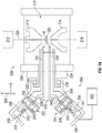
- a multi-beam system can be configured as a dual-beam system 100 comprising a scanning electron microscope (SEM) generally indicated at 102 and an ion beam column generally indicated at 104.
- the SEM 102 can comprise one or more charged particle beam (CPB) lenses such as a condenser lens 116 and an objective lens 106.
- CPB charged particle beam
- one or more CPB lenses can be magnetic lenses, and particularly, the objective lens 106 can be a magnetic objective lens.
- the ion beam column is arranged to provide a focused ion beam (FIB) to a workpiece W, and the SEM 102 is situated for production of an image of the workpiece W.
- FIB focused ion beam
- the SEM 102 and the ion beam column 104 can be mounted to a vacuum chamber 108 housing a movable positioning system 110 for holding the workpiece W.
- the vacuum chamber 108 can be evacuated using vacuum pumps (not shown).
- the positioning system 110 can be movable along the X-, Y-, and/or Z- axes as shown with respect to a coordinate system 150, wherein the Y-axis is perpendicular to the plane of the page.
- the SEM 102 can be arranged vertically above the workpiece W and can be used to image the workpiece W, and the ion beam column 104 can be arranged at an angle and can be used to machine and/or process the workpiece W.
- FIG. 1 shows an exemplary orientation of the SEM 102 and the ion beam column 104.
- the SEM 102 can comprise an electron source 112 and can be configured to manipulate a "raw" radiation beam from the electron source 112 and perform upon it operations such as focusing, aberration mitigation, cropping (using an aperture), filtering, etc.
- the SEM 102 can produce a beam 114 of input charged particles (e.g., an electron beam) that propagates along a particle-optical axis 115.
- the SEM 102 can generally comprise one or more lenses (e.g., CPB lenses) such as the condenser lens 116 and the objective lens 106 to focus the beam 114 onto the workpiece W.
- the SEM 102 can be provided with a deflection unit 118 that can be configured to steer the beam 115.
- the beam 114 can be steered in a scanning motion (e.g., a raster or vector scan) across a sample being investigated or a workpiece to be processed.
- the dual-beam system 100 can further comprise a computer processing apparatus and/or a controller 128 for controlling, among other things, the deflection unit 118, charged particle beam (CPB) lenses 106, 116, and detectors (not shown), and for displaying information gathered from the detectors on a display unit.
- a control computer 130 is provided to establish various excitations, record imaging data, and generally control operation of both the SEM and the FIB.
- the ion beam column 104 can comprise an ion source (e.g., a plasma source 120) and ion beam optics 122.
- the ion beam column 104 is a plasma focused ion beam (PFIB), however, in other embodiments, the ion beam column 104 can be a standard focused ion beam (FIB) having a liquid metal ion source (LMIS), or any other ion source compatible with a focused ion beam column.
- the ion beam column 104 can produce and/or direct the ion beam 124 along an ion-optical axis 125.
- the ion column 104 can be used to perform imaging, processing and/or machining operations on the workpiece, such as incising, milling, etching, depositing, etc.
- the ion source 120 can be fluidly coupled to a plurality of gases via a gas manifold 165 that includes gas sources coupled by respective valves to the ion source 120.
- a gas can be introduced, where it becomes charged or ionized, thereby forming a plasma. Ions extracted from the plasma can then be accelerated through the ion beam column 104, becoming an ion beam.
- the system 100 can comprise one or more lasers, or other types of milling or diagnostic tools.
- such multi-beam systems can comprise a positioning system (e.g., a stage) configured to hold and position the workpiece W.
- the positioning system can position/move a carrier element in multiple degrees of freedom, including linear movement (e.g., to choose a particular area for analysis on a workpiece) and/or angular or rotational movement (e.g., to achieve a selected angle of the workpiece relative to an instrument).
- the positioning system can include one or more piezo actuators in which the disclosed clamp compensation systems and methods can be used.
- FIGS. 2A and 2B show cross-sectional views of an exemplary positioning system 200 coupled to a beam system configured as a charged particle microscope (CPM) generally indicated at 208.
- the positioning system 200 can comprise one or more drive units.
- the system can comprise three drive units, of which two drive units 202 and 204 can be seen in FIG. 2 .
- the drive units 202, 204 are configured as walking or stepping piezo drive units, such as Heinmade Piezo Stepper (HMPS) actuators available from Heinmade BV.
- HMPS Heinmade Piezo Stepper
- the drive units can comprise other types of actuators, such as other types of piezo actuators, voice coil motors, rack and pinion systems, linear motors, etc.
- the first and second drive units 202, 204 can be configured to position the workpiece W along at least the X- and Z-axes of the coordinate system 206 defined with respect to the beam system 208.
- the positioning system can comprise three or more drive units, allowing for movement of the workpiece along the X-, Y-, and Z- axes.
- the positioning system can comprise three drive units oriented such that each drive unit is offset from the others by 120 degrees.
- the positioning system 200 can be used with multi-beam systems, such as the CPM 208.
- the CPM 208 can be, for example, a scanning electron microscope (SEM), transmission electron microscope (TEM), or a combination scanning and transmission electron microscope (STEM).
- the CPM 208 can comprise a beam source 210, an upper pole objective lens 212, a lower pole objective lens 214, a detector 216 (e.g., a camera, a photomultiplier, photodiode, CMOS detector, CCD detector, photovoltaic cells, etc.).
- the components can be positioned at least partially within a vacuum chamber 218.
- a carrier element 220 including a workpiece W positioned thereon is shown extending from the positioning system 200 into the vacuum chamber 218.
- Positioning system 200 can comprise a frame or housing 222 mounted on an external surface 224 of the CPM 208 (e.g., an external surface of the vacuum chamber 218).
- the housing 222 can be mounted to the surface 224 using one or more bearings 226, which allow the housing 222 to tilt or rotate (e.g., about the x-axis) relative to the surface 224.
- the bearings 226 can be coupled to a mounting element 228 disposed on the surface 224 of the CPM 208.
- the housing 222 can be disposed such that a portion of the housing comprising the carrier element 220 for holding the workpiece W can extend through an opening in the side of the CPM 208 and at least partially into the vacuum chamber 218.
- the positioning system 200 can be configured to adjust the position of the workpiece W relative to the beam 230 by using the drive units (e.g., first and second drive units 202, 204) to adjust the position of the carrier element 220, as described in more detail below.
- the carrier element 220 can be coupled to first and second guides 232, 234. Each guide 232, 234 can be further coupled, via respective joints 236 (e.g., a hinge, knuckle joint, ball joint, etc.) to a respective strut member 238, 240.
- the strut 238 can be pivotably coupled to a mover element or member 242 at a pivot joint 239, and the strut 240 can be pivotably coupled to a mover element or member 244 at a pivot joint 241.
- the first and second drive units 202, 204 can be configured to engage the mover elements 242 and 244, respectively.
- the drive unit 202 can be configured to move the mover element 242 along its axis toward and away from a rear wall 243 of the housing 222 in a series of step motions, as described in greater detail below.
- the drive unit 204 can be configured to move the mover element 244 along its axis toward and away from a rear wall 245 of the housing 222, similar to the mover element 242.
- the struts 238, 240 (along with the mover elements and the drive units) can be positioned at an angle relative to one another such that motion of the mover element 242 away from the rear wall 243, along with motion of the mover element 244 toward the rear wall 245 can cause the carrier element 220 to tilt out of the X-Y plane, as shown in FIG. 2B .
- Simultaneous movement of the mover elements 242 and 244 away the walls 243 and 245, and toward the CPM 208, can move the carrier element 200 along the X-axis.
- the mover elements 242 and 244 are positioned at an angle of 90° relative to one another.
- three drive units and corresponding mover elements can be arrayed around the axis of the carrier element 220 with an angular spacing of 120°.
- Each mover element 242, 244 can comprise a respective encoder scale 246.
- First and second position encoders 248 and 250 mounted to the housing 222 can be configured to determine the position of each mover element 242, 244, respectively, based on the encoder scales 246.
- the encoder scales 246 can be coupled to or formed integrally with the movers 242, 244.
- FIG. 3 illustrates a schematic diagram of an exemplary position encoder 300.
- An encoder scale 302 is mounted to a mover, which can be positioned between a light source 304 and a detector 306.
- the light source and the detector can be mounted to the housing of the positioning system.
- a beam 308 produced by the light source 304 is split into two beams 310, 312 when passing through the encoder scale 302.
- Two mirrors 314, 316 are used to reunite the beams and direct the united beam 318 into the detector 306.
- each encoder 248, 250 can be configured to determine the position of the respective mover element 242, 244.
- the location data generated by the encoders 248, 250 can be used by a controller 252 to operate the actuators 202, 204 to position the mover elements 242, 244 at a selected location, thereby positioning the workpiece W at a selected location, as described in more detail below.
- the positioning system can include one or more piezo actuators in which the disclosed clamp compensation systems and methods can be used.
- FIGS. 4A and 4B illustrate an exemplary drive unit 400 in greater detail, which may be configured for use with the positioning system as either the drive unit 202 or 204.
- the drive unit 400 can engage a mover member or element 402. As described above, the mover element 402 can be coupled to the carrier element, and can therefore position the workpiece W relative to the CPM 208 or other instruments in the vacuum chamber 218.
- the drive unit 400 can be a piezo drive unit comprising two sets of actuators 404, 406 housed within first and second frame or housing portions 408, 410.
- each actuator set can comprise three movable members, referred to herein as actuators.
- Each actuator in turn, can comprise one or more actuator elements, such as a shear element, a clamp element, or various combinations thereof.
- Each of the actuator elements can be independently movable and/or controllable.
- the actuator sets can comprise a greater or fewer number of actuators.
- each set of actuators comprises an equal number of actuators, in other embodiments one set of actuators can comprise more or fewer actuators than the other.
- the first set of actuators can comprise three actuators and the second set of actuators can comprise four actuators, etc.
- the first set of actuators 404 can comprise a first actuator 404a disposed adjacent a first surface 412 of the mover element 402, and second and third actuators 404b, 404c disposed on the opposite side of the mover element 402 adjacent a second surface 414 of the mover element.
- the first actuator 404a comprises a shear element 420 and a clamp element 422, and the second and third actuators 404b, 404c comprise shear elements.
- the clamp and/or shear elements can frictionally engage the mover element 402 in order to move the mover element 402 in a selected direction, as described in more detail below.
- the second set of actuators 406 can comprise a first actuator 406a disposed adjacent the second surface 414 of the mover element 402, and second and third actuators 406b, 406c disposed adjacent the first surface 412 of the mover element 402.
- the first actuator 406a comprises a shear element 424 and a clamp element 426
- the second and third actuators 406b, 406c comprise shear elements.
- the two sets of actuators 404, 406 can be actuated in an alternating, stepping, or "walking" motion such that when the first set of actuators 404 engages with and exerts force on the mover element 402, the second set of elements 406 disengages or releases the mover element, and vice versa. There can be a brief period between steps when both sets of actuators 404 and 406 are in contact with the mover 402. This is referred to as a "takeover" condition, when one set of actuators "takes over" from the other set of actuators.
- This configuration wherein one actuator of a set engages the first surface of the mover element and the second and third actuators of the set engage the second surface of the mover element helps mitigate distortion during operation, and can provide smoother motion of the mover element.
- the alternating takeover movement between the two sets of actuators advantageously minimizes slipping between the actuators and the mover element.
- this configuration allows for an extension of the stroke length of the drive unit without affecting the stiffness or motion performance.
- the shear elements When actuated, the shear elements can be displaced along the Z-axis, as shown with respect to coordinate system 416, wherein the Z-axis is perpendicular to the plane of the page in FIG. 4A and parallel to the plane of the page in FIG. 4B .
- the clamp elements can be displaced along the Y-axis.
- a large movement stroke can be achieved by alternating actuation of the sets of actuators.
- the first frame portion 408 can be coupled to a biasing member 418 (e.g., a spring) that allows the first frame portion 408 to move relative to the mover element 402.
- a biasing member 418 e.g., a spring
- the biasing member 418 can be biased into an expanded position in order to maintain frictional contact between the actuators housed in the first portion of the frame 408 and the mover element 402.
- the end portions (e.g., the portions adjacent the mover element) of the actuators can be coated with aluminum oxide to mitigate wear on the actuators and to extend the lifetime of the driving unit.
- each of the clamp and/or shear elements can comprise a wear resistant plate configured to mitigate damage to the clamp and/or shear elements from frictional engagement with the mover.
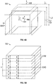
- FIGS. 5A-5B show an exemplary embodiment of a clamp element 500
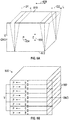
- FIGS. 6A-6B show an exemplary embodiment of a shear element 600.
- the clamp elements and shear elements comprise piezoelectric elements.
- the clamp element 500 can be a longitudinal piezo element and the shear element 600 can be shear piezo element.
- the longitudinal piezo element 500 can be configured to deform or elongate axially when a voltage is applied, and the shear piezo element 600 can be configured such that one end is laterally displaced with respect to the opposite end when a voltage is applied, as explained in detail below.
- each element 500, 600 can comprise a plurality of piezoelectric members 502, 602 disposed adjacent to one another.
- the clamp and shear elements 500, 600 can be single layer piezo elements, or monolithic multi-layer piezo elements, also called monolithic co-fired piezo elements.
- the displacement of a clamp and/or shear element can be linearly related to the applied voltage.
- the piezo members 502, 602 are polarized, it can be considered a longitudinal element or a shear element.
- the clamp elements can move between a first, or neutral configuration, a second elongated configuration (e.g., when energized by applying a positive voltage), and/or a third shortened configuration (e.g., when energized by applying a negative voltage).
- the electrical field (shown by arrow 506) can be applied parallel to the direction of polarization (shown by arrow 504).
- the clamp element can comprise eight piezo layers, however, in other embodiments, the clamp element can comprise a greater or fewer number of layers. In some particular embodiments, the clamp element can comprise three piezo layers.
- the voltage applied to the clamp element can be, for example, between -30 V and 60 V.
- the clamp element 500 When energized (e.g., by applying a positive or negative voltage), the clamp element 500 can expand and/or contract longitudinally, that is, in the direction shown by arrow 508.
- the clamp element 500 can have a first or neutral configuration having a first or natural length L 1 when no voltage is applied to the clamp element, a second or expanded configuration having a second length L 2 when a first or positive voltage is applied to the element, and a third or contracted configuration having a third length L 3 when a second or negative voltage is applied to the element.
- the second length L 2 can be greater than the first length L 1 , which can be greater than the third length L 3 .
- the length can be based at least in part on the magnitude of the applied voltage.
- FIGS. 6A and 6B illustrate an exemplary shear piezo element 600.
- the electrical field shown by arrow 606
- the shear element 600 can comprise eight layers of piezo members.
- the shear element can comprise a greater or fewer number of layers.
- the shear element 600 can comprise four layers of piezo members.
- the voltage applied to the shear actuator can be, for example, between -250 V and 250 V.
- a portion of the shear element 600 can shear or move laterally in a selected direction as shown by arrow 608.
- the shearing motion causes displacement of a first surface 610 of the shear piezo element relative to a second surface 612 on the opposite side of the shear element.
- the shear element can have a first offset position wherein the first surface is displaced from the second surface in a first direction by a first displacement length D 1 when a positive voltage is applied, and a second offset position wherein the first surface is displaced from the second surface in a second direction (e.g., opposite the first direction) by a second displacement length D 2 when a negative voltage is applied.
- the displacement lengths D 1 and D 2 can be based at least in part on the magnitude of the applied voltage.
- the piezoelectric members 502 and 602 can include but are not limited to ceramics (including naturally occurring and synthetic ceramics), crystals (including naturally occurring and synthetic crystals), group III-V and II-VI semiconductors, polymers, organic nanostructures, or any combinations thereof.
- the piezoelectric elements can comprise lead zirconium titanate (PZT). Such piezoelectric elements can expand when a positive voltage is applied and contract when a negative voltage is applied. The magnitude and speed of contraction, expansion, and/or shear displacement can be dependent on the magnitude of the voltage applied to the piezo members.
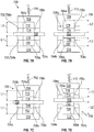
- FIGS. 7A-7D show the positions of the actuators of an exemplary drive unit 700 (which can be configured similarly to the drive unit 400) throughout a drive cycle.
- the drive unit 700 is configured to engage a mover element 702.
- the drive unit 700 comprises two sets of actuators 704 and 706.
- Each actuator set can comprise three actuators.
- the actuator set 704 can comprise actuators 704a, 704b, and 704c
- the actuator set 706 can comprise actuators 706a, 706b, and 706c.
- the actuators can comprise shear elements, clamp elements, and/or a combination thereof.
- actuators 704b, 704c, 706b, and 706c comprise shear elements.
- the actuator 704a can comprise a shear element 714 and a clamp element 716, and the actuator 706a can comprise a shear element 718 and a clamp element 720.
- the actuators can be housed in first and second frame portions 708, 710.
- the displacement of the actuators can be linearly related to the voltage applied.
- four drive signals can be used to move the sets of actuators 704, 706 in an alternating manner.
- the drive signals can be configured as waveforms (e.g., voltage waveforms) due to the repetitive nature of the alternating or walking movement.
- the actuators 704a and 706a have equal lengths, however, in other examples, the actuators 704a and 706a can have different lengths.
- a drive unit can comprise a greater or fewer number of clamp and shear elements.
- FIGS. 8A and 8B illustrate the drive signals for the drive cycle shown in FIGS. 7A-7D .
- the drive signals can be dependent on the commutation angle ⁇ and can be periodic with a period of 2 ⁇ .
- FIG. 8A shows an exemplary driving or voltage signal for the clamp elements of the first and second sets of actuators
- FIG. 8B shows an exemplary driving or voltage signal for the shear elements of the first and second sets of actuators.
- a first voltage signal 800 can be applied to the clamp element 716 of the first actuator set 704 and a second voltage signal 802 can be applied to the clamp element 720 of the second actuator set 706.
- the voltage signals in FIG. 8A ramp up and down at a constant rate between -30 V and 60 V.
- the drive signal of the clamp element 716 can be ⁇ rad out of phase with the drive signal of the clamp element 720 such that when the voltage applied to the clamp element 716 is 60 V, the voltage applied to the clamp element 720 is -30 V and vice versa. Both signals have the same period, maximum value, and minimum value. However, in other embodiments the drive signal of the clamp element 716 may be different from the drive signal of the clamp element 720.
- the voltage signals in 804 and 806 FIG. 8B can increase or ramp up from -250 V to 250 V at a first rate through an angle of 3 ⁇ 2 rad , and can decrease or ramp down from 250 V back to -250 V at a second rate over an angle of ⁇ 2 rad in the manner of a sawtooth wave.
- the signals in FIG. 8B can also be out of phase or phase-shifted by ⁇ rad.
- FIG. 7A shows the drive unit 700 in a first or starting position in the drive cycle wherein the commutation angle is zero. This position corresponds with the drive signal values at a commutation angle of 0 rad in FIGS. 8A and 8B , indicated by reference letter a .
- the voltage applied to the clamp elements 716 and 720 of the actuators 704a and 706a is equal at 0 rad such that both actuators have an equal length L 1 , and engage and clamp the mover element 702 between them.
- the voltage applied to the shear elements of the actuators 704b and 704c, and to the shear element 714 of the actuator 704a can be -200 V.
- the voltage applied to the shear elements 706b and 706c, and to the shear element 720 of the actuator 706a can be 200 V. Therefore, the actuators 704b, 704c, 706b, and 706c are also in contact with the mover element 702.
- the position of the actuators in FIG. 7A can correspond to the "takeover" movement wherein all elements of both sets of actuators 704, 706 are in equilibrium with each other, and in contact with the mover 702.
- the derivative with respect to the commutation angle of the shear-voltages of the shear elements in both shear groups can be equal. Accordingly, both shear groups can move with the same velocity.
- FIG. 7B shows the drive unit in a second exemplary position in the drive cycle, corresponding to the portion of the drive signal shown by reference letters b-c in FIGS. 8A and 8B .
- the clamp element 716 of the actuator 704a of the first set of actuators 704 is energized with a maximum voltage, thus moving the actuator 704a from the first length L 1 to an expanded length L 2 that is greater than L 1 .
- the voltage applied to clamp element 716 of actuator 704a can be 60 V and the voltage applied to the clamp element 720 of actuator 706a can be -30 V.
- the expanded length L 2 of the actuator 704a moves the first frame portion 708 relative to the mover element 702, such that the actuators 706b and 706c no longer engage the mover element 702.
- the first frame portion 708 can be coupled to a biasing element 712.
- the biasing element 712 (e.g., a spring) can compress to allow movement of the first frame portion 708 relative to the mover element 702.
- the clamp element 720 of the actuator 706a meanwhile is energized with its minimum voltage (e.g., -30 V), thus moving the actuator 706a from the first length L 1 to a contracted configuration having length L 3 , smaller than length L 1 such that the actuator 706a no longer engages the mover element 702.
- Actuators 706b and 706c are in position for the next "takeover" movement, while the actuators 704b, 704c, and 714 move, displace, or drive the mover element 702 with respect to the drive unit 700 under the influence of the increasing driving voltage in FIG. 8B .
- the voltage applied to shear elements 718, 706b, and 706c can drop from 250 V to -250 V and the voltage applied to shear elements 714, 704b, and 704c can rise from -250 V to 250 V.
- FIG. 7C shows the actuator in a third exemplary position in the drive cycle, corresponding to the portion of the drive signals indicated by reference letter d in FIGS. 8A and 8B .
- the third exemplary position is a second "takeover" movement similar to the takeover movement described above with respect to FIG. 7A in which all of the actuators are in contact with the mover element 702.
- the voltage applied to the clamp elements 716 and 720 of the actuators 704a and 706a is equal at 0 rad such that both actuators have an equal length L 1 , and engage and clamp the mover element 702 between them.
- the voltage applied to the shear elements of the actuators 704b and 704c, and to the shear element 714 of the actuator 704a can be 200 V.
- the voltage applied to the shear actuators 706b and 706c, and to the shear element 718 of the actuator 706a can be -200 V.
- FIG. 7D shows the actuator in a fourth exemplary position in the drive cycle, corresponding to the portion of the drive signal shown by reference letters e-f in FIGS. 8A and 8B .
- This position is similar to the position shown in FIG. 7B , except that the second set of actuators 706 is engaged with the mover element 702 and the first set of actuators 704 are disengaged.
- the clamp element 720 of the actuator 706a is energized with a maximum voltage, thus moving actuator 706a from length L 1 to an expanded configuration having length L 2 greater than L 1 .
- the voltage applied to clamp element 720 of actuator 706a can be 60 V and the voltage applied to clamp element 716 of actuator 704a can be -30 V.
- the expanded configuration of the actuator 706a can move the mover element 702 (and thereby the elements 704a, 706b, 706c and the first frame portion 708) relative to (e.g., away from) the second frame portion 710, such that actuators 704b and 704c no longer engage the mover element 702.
- the clamp element 716 is energized with its minimum voltage (e.g., - 30 V), thus moving the actuator 704a from the first length L 1 to a contracted configuration having length L 3 , smaller than length L 1 such that actuator 704a is not engaged with the mover element 702.
- Actuators 704b and 704c are in position for the next "takeover" movement, while actuators 706b and 706c drive or displace the mover element 702 due to the increasing driving voltage in FIG. 8B .
- the voltage applied to shear elements 718, 706b, and 706c can rise from -250 V to 250 V and the voltage applied to shear elements 714, 704b, and 704c can drop from 250 V to -250 V.
- the configuration of the drive unit corresponding to the portion of the drive signal shown by the reference letter g in FIGS. 8A and 8B is the same as the configuration shown in FIG. 7A .
- This combination of piezo elements and drive signals enables the drive unit to move the mover element 702 in a series of steps reminiscent of a walking motion.
- This drive cycle can be repeated as necessary in order to move the mover element 702 to a selected position.
- the direction of the drive signals can also be reversed in order to move the mover element in the opposite direction.
- the drive unit(s) can be used to move the mover(s), thereby positioning the workpiece W relative to a charged particle microscope (CPM), for example, a STEM.
- CPM charged particle microscope
- Disturbances in the position and velocity of the workpiece W can be undesirable for tracking point to point movements of the workpiece W travelling at constant velocity.
- disturbances can cause the guidance system to lose track of the positioning of the workpiece and/or a selected area of the workpiece that is meant to be imaged.
- the CPM can be configured to image the workpiece W while the workpiece is in motion. In such embodiments, it is particularly advantageous to have smooth and consistent movement of the workpiece W.
- actuators 902, 904 of a drive unit 900 are typically positioned such that they are perpendicular to the mover element 906.
- the actuators 902, 904 can be positioned such that an axis 908 extending longitudinally through the actuators 902, 904 would form a 90° angle with the surface of the mover element 906.
- the surface of the actuators 902, 904 that contacts the contact surface 910 of the mover element is parallel to the mover element 906, and the actuators move perpendicularly relative to the surface of the mover.
- this configuration allows actuators that comprise a clamp element to engage the mover element without affecting the position of the mover element.
- one or both of the actuators 1002, 1004 of the drive unit 1000 can be positioned at an angle (e.g., at a tilt) relative to the mover element 1006. This can be referred to as 'misalignment of the clamp elements.
- the surface of the actuator that contacts the contact surface 1012 mover element is not parallel to the surface 1012 and the actuators move at a non-perpendicular angle with respect to the mover element.
- practical limitations regarding tolerances in the dimensions and/or position of components within the system can result in one or both of the actuators 1002, 1004 being angled or tilted with respect to the mover element 1006.
- Tilted actuators 1002, 1004 can result in changes (e.g., additions or subtractions) in the velocity of the shear elements, thereby creating disturbances in the position and velocity of the workpiece W.
- an angled actuator element may contact the surface of the mover before the commutation angle ⁇ at which a perpendicular actuator would be expected to make contact. This can push the mover forward or backward as the actuator continues to elongate, depending upon the direction of the misalignment.
- the disturbances caused by a tilted actuator can be quantified using, for example, an open-loop clamping measurement.
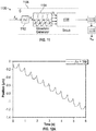
- Exemplary control architecture 1100 for such an open-loop measurement is shown in FIG. 11 .
- the control system 1100 can comprise an integrator tool or module 1102 and a signal generator module 1104.
- the drive unit is represented at block 1106.
- the blocks 1102, 1104, and 1106 are grouped together inside a block 1108 representative of the physical system G (e.g., which can include a carrier unit, a drive unit, a position encoder, etc.).
- a driving frequency f ⁇ can be inputted to the integrator module 1102.
- the integrator module 1102 can output a commutation angle ⁇ to the signal generator 1104, which can generate a plurality of (e.g., four) output signals u i to the drive unit 1106. Since there are two types of piezo elements (e.g., shears and clamps) and two sets of piezo actuators in the illustrated embodiment (see e.g., FIGS. 7A-7D ), the signal generator can output four signal or voltage functions u i to move the drive unit in the selected manner. In one representative embodiment, the clamp elements can be energized with the clamp element drive signal while the shear elements are kept stationary.
- the influence of the tilted clamp elements on the position of the mover element x m can be determined.
- the displacement of the mover element can be determined.
- the clamp elements of the actuators can be energized using a drive signal while the shear elements of the actuators remain stationary at 0 V.
- the influence of the tilted clamp elements on the position of the mover element can be determined.
- FIGS. 12A-12B show exemplary position and velocity measurements determined using the open-loop measurement
- FIG. 12A shows an exemplary position evaluation using a constant drive frequency f ⁇ of 1 Hz
- FIG. 12B shows an exemplary velocity evaluation using a constant drive frequency f ⁇ of 1 Hz.
- the velocity signal is repetitive, and therefore, the disturbances in the position signal are repetitive.
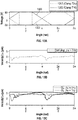
- the disturbances in velocity, and therefore position can be related to the drive signal applied to the clamp elements and to the directional dependence of the open-loop response, as shown in FIGS. 13A-13C .
- the velocity can be zero.
- FIG. 13A shows the typical drive signal applied to the clamp elements of the actuators.
- FIG. 13B shows the normalized velocity evolution for a clamping measurement having a drive frequency of 1 Hz.
- FIG. 13C shows the normalized velocity evolution for a clamping element driven by the open-loop control system 1100 with f ⁇ ⁇ -1, 1 ⁇ Hz.
- the mover e.g., the clamp element of the first set of actuators or the clamp element of the second set of actuators. Accordingly, the increase and decrease in velocity can be the result of a tilted clamp element.
- the disturbances caused by one or more tilted clamp elements of the actuators can be at least partially offset or mitigated by actuating the shear elements to compensate for the tilt or misalignment of the clamp elements.
- angled clamp elements can be at least partially compensated for by modifying the waveform of the drive signal(s) of the shear elements to provide a modified drive signal (e.g., a signal comprising an initial shear signal in combination with a compensation signal) to the shear elements of the actuators.
- An exemplary compensation signal can be produced by superposition of the velocity as a result of the clamping measurement and the open-loop measurement.
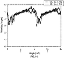
- FIG. 14 shows the normalized open-loop velocity signal for 1 Hz and -1 Hz corrected with the clamping velocity signal based on a superposition of shear and clamp velocity. It can be seen in FIG. 14 that that the minima at ⁇ ⁇ ⁇ 0.1 ⁇ 1.15 ⁇ ⁇ rad are reduced to approximately 0 m/s. Thus, in certain embodiments, with the tilt compensation algorithms described herein, at least the negative velocities can be avoided.
- Misalignment, displacement, and/or tilt of the clamp element with respect to the mover element can be at least partially compensated for by modifying the motion of the shear elements.
- the displacement trajectory of the shear elements can be determined based at least in part on the observed displacement of the mover element when acted upon by the clamping elements.
- the shear elements can have a stroke length of approximately 3.0 x 10 -6 m when a voltage signal with an amplitude of 250 V is applied. Accordingly, the voltage required to create a certain shear displacement can be approximated by the model given below in Equations 1 and 2.
- the inverse shear constant ⁇ -1 relates the applied voltage to the shear displacement of the shear piezo elements.
- ⁇ -1 is the inverse shear constant [V/m]
- u is the applied voltage [V]
- x m is the position of the mover element [m].
- the displacement of the mover element when clamped by a clamping element should be 0 m.
- the shear compensation signal or waveform can be generated using an iterative learning control (ILC) scheme and an inverse shear model, such as shown by Equation 3.
- ILC iterative learning control
- u j + 1 u j ⁇ G ⁇ ⁇ 1 x m
- Equation 3 u j +1 is the adjusted compensation signal [V]
- u j is the initial compensation signal [V]
- ⁇ -1 is the inverse shear constant [V/m]
- x m is the displacement of the mover [m].
- FIGS. 15A and 15B show initial voltage waveforms for the clamping elements and the shear elements that can be used with an ILC system to tune the shear element drive signal.
- FIG. 15A shows the typical drive signal applied to the clamp elements of the actuators during operation of the drive unit in order to move the clamp elements in a first direction (e.g., toward or away from the mover element)
- FIG. 15B shows an initial drive signal, referred to herein as a compensation signal or waveform, to be applied to the shear elements of the actuators in order to move the shear elements in a second direction (e.g., opposite from the direction of movement of the mover element).
- the initial voltage signal for the shear elements can be based at least in part on the path of the mover element during a clamping operation in which there is no compensation for misalignment.
- the initial voltage waveform for driving the shear elements can be obtained by multiplying the position of the mover x m with the inverse shear constant ⁇ -1 , and subtracting the resultant quantity from the initial, unmodified shear element voltage signal according to Equation 3 above. The clamps can then be actuated again, and the shear elements can be driven with the waveform resulting from Equation 3.
- the shear elements can move in the second direction (e.g., opposite the direction of movement of the mover element) to compensate at least in part for misalignment between the clamp element and the mover element.
- the total sum of the error can be compared with a target displacement or path (e.g., 0 m, or no movement).
- a second shear element voltage signal can then be determined based at least in part on the difference between the measured displacement of the mover element and the target displacement.
- a preselected threshold e.g. 1 ⁇ m, 100 nm, 10 nm, etc.
- the retracting motion of the shear elements can be oriented such that this group is not in contact with the mover element during clamping, meaning that any changes in the position of the mover element can be caused by misalignment of the clamp elements.
- the drive signal for the shear elements can be modified iteratively by repeating the process above in order to reduce movement of the mover element during clamping by the clamping elements. The process can be repeated until the displacement of the mover element converges to the target displacement, or near to the target displacement.
- FIG. 16 shows the evolution of the drive signal over 8 iterative trials of the ILC scheme. For each trial the drive signal of the shear elements is modified in order to reduce the change in position of the mover element. In certain embodiments, it is possible to reduce displacement of the mover element by a factor of 60 or more as compared to operation of the driving unit without compensating for clamp misalignment.
- the shear element waveform that results in zero displacement, near zero displacement, or a preselected displacement of the mover element is referred to herein as the compensation waveform or compensation drive signal.
- a compensation drive signal such as the compensation drive signal associated with FIG. 16 can be combined with the initial or unmodified shear element drive signal (see e.g., FIG. 8B ).
- the maximum voltage to the shear elements can not exceed 250 V, so the amplitude of the initial waveform is reduced to 150 V.
- the resulting drive signals are shown in FIGS. 17A-17B.
- FIG. 17A shows the drive signal applied to the clamp elements
- FIG. 17B shows the modified or compensated shear element drive signal resulting from combining the compensation waveform with the initial shear drive signal.
- the resulting modified drive signal shown in FIG. 17B is configured to move the mover element to a target position (or by a selected distance per cycle) while mitigating movement of the mover element caused by clamp element misalignment.
- FIG. 18A shows the uncompensated and compensated position evolution for a drive unit.
- the frequency of the drive signals can be 1 Hz.
- the uncompensated drive signal can be similar to the drive signals shown in FIGS. 8A and 8B
- the compensated drive signal can be similar to the drive signals shown in FIGS. 17A and 17B .
- the compensated position evolution 1802 is smoother and has fewer perturbations than the uncompensated position evolution 1800.
- FIG. 18B shows the uncompensated and compensated velocity over one drive signal cycle.
- the compensated velocity 1804 has no negative velocities, and is smoother and has shallower changes than the uncompensated velocity 1806. With tilt compensation, the minima in velocity evolution can be reduced to ⁇ m ⁇ 0 m/s.
- the same compensation signal can be applied to open-loop measurements with a different drive frequency.
- FIG. 19 illustrates an exemplary control system 1900 for closed-loop processing used to implement the processes described herein.
- the control system 1900 can comprise an integrator tool or module 1902 and a signal generator module 1904.
- the drive unit is represented at block 1906.
- the blocks 1902, 1904, and 1906 are grouped together inside a block 1908 representative of the physical system G (e.g., a carrier element, a drive unit, and/or a position encoder, etc.).
- a summing junction sums a preselected threshold value r (e.g., between 10 nm and 100 nm) and x m (the displacement of the mover element) resulting in an error value e.
- the error value can then but inputted into a controller 1910.
- the controller 1910 can generate a driving frequency f ⁇ , which can be inputted into the integrator module 1902.
- the integrator module 1902 can output a commutation angle ⁇ to the signal generator 1904, which can generate a plurality of (e.g., four) output voltage signals u i to the drive unit 1906, resulting in a positional change x m .
- the output signal to the shear elements generated by the waveform generator 1904 can be a compensated drive signal based at least in part on predetermined motion of the mover element during clamping.
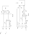
- a representative method 2000 for positioning a mover element of a positioning system using a drive unit comprises applying a first drive signal to a clamp element of a drive unit such that the clamp element moves in a first direction toward the mover element at 2002.
- a second drive signal can be applied to at least one shear element of the drive unit such that the shear element moves in a second direction to compensate for misalignment between the clamp element and the mover element.
- a representative method 2100 for generating a compensated drive signal for a drive unit comprises applying a clamp element drive signal to a clamp element of a drive unit, the clamp element configured to engage a mover element at 2102.
- a displacement of the mover element is determined.
- a compensation signal to be applied to one or more shear elements of the drive unit is determined, based at least in part on the displacement of the mover element.
- the compensation signal is applied to the one or more shear elements and the clamp element drive signal is applied to the clamp element.
- a second displacement of the mover element is determined.
- the compensation signal is combined with an initial shear element drive signal to create a modified or compensated shear element drive signal.
- a representative method 2200 for determining a modified shear element drive signal comprises applying a clamp element drive signal to a clamp element at 2202.
- a displacement of the mover element can be measured (e.g., using a position encoder).
- the displacement can be used to determine a compensation signal.
- the clamp element drive signal can be applied to the clamp element and the compensation signal can be applied to one or more shear elements.
- the displacement of the mover element can be measured again.
- the compensation signal can be combined with an initial shear element drive signal to create a modified shear element drive signal at 2214.
- the modified shear element drive signal can be applied to the one or more shear elements and the clamp element drive signal can be applied to the clamp element.
- the displacement of the mover element can be used to determine an additional compensation signal at 2206. Acts 2206 through 2212 can be repeated until the displacement of the mover element is below the preselected threshold.
- FIG. 23 and the following discussion are intended to provide a brief, general description of an exemplary computing environment in which the disclosed technology may be implemented.
- controller 252 can be configured similarly to the computing environment described below.
- the disclosed technology may be implemented with other computer system configurations, including hand held devices, digital signal processors (DSPs), multiprocessor systems, microprocessor-based or programmable consumer electronics, network PCs, minicomputers, mainframe computers, and the like.
- DSPs digital signal processors
- multiprocessor systems multiprocessor systems
- microprocessor-based or programmable consumer electronics network PCs
- minicomputers minicomputers
- mainframe computers and the like.
- the disclosed technology may also be practiced in distributed computing environments where tasks are performed by remote processing devices that are linked through a communications network.
- an exemplary system for implementing the disclosed technology includes a general-purpose controller in the form of an exemplary conventional PC 2300, including one or more processing units 2302, a system memory 2304, and a system bus 2306 that couples various system components including the system memory 2304 to the one or more processing units 2302.
- the system bus 2306 may be any of several types of bus structures including a memory bus or memory controller, a peripheral bus, and a local bus using any of a variety of bus architectures.
- the exemplary system memory 2304 includes read only memory (ROM) 2308 and random-access memory (RAM) 2310.
- ROM read only memory
- RAM random-access memory
- a basic input/output system (BIOS) 2312 containing the basic routines that help with the transfer of information between elements within the PC 2300, is stored in ROM 2308.
- data and processor-executable instructions for controlling motion of the positioning system, imaging, processing, and other operational modes of an SEM and a FIB are stored in a memory 2310A, and data and processor-executable instructions for identifying and quantifying beam components are stored in memory 2310B.
- the exemplary PC 2300 further includes one or more storage devices 2330 such as a hard disk drive for reading from and writing to a hard disk, a magnetic disk drive for reading from or writing to a removable magnetic disk, and an optical disk drive.
- storage devices can be connected to the system bus 2306 by a hard disk drive interface, a magnetic disk drive interface, and an optical drive interface, respectively.
- the drives and their associated computer readable media provide nonvolatile storage of computer-readable instructions, data structures, program modules, and other data for the PC 2300.
- Other types of computer-readable media which can store data that is accessible by a PC such as magnetic cassettes, flash memory cards, digital video disks.
- a number of program modules may be stored in the storage devices 2330 including an operating system, one or more application programs, other program modules, and program data.
- a user may enter commands and information into the PC 2300 through one or more input devices 2340 such as a keyboard and a pointing device such as a mouse.
- a monitor 2346 or other type of display device is also connected to the system bus 2306 via an interface, such as a video adapter.
- the PC 2300 may operate in a networked environment using logical connections to one or more remote computers, such as a remote computer 2360.
- a remote computer 2360 may be another PC, a server, a router, a network PC, or a peer device or other common network node, and typically includes many or all of the elements described above relative to the PC 2300, although only a memory storage device 2362 has been illustrated in FIG. 23 .
- the personal computer 2300 and/or the remote computer 2360 can be connected to a logical a local area network (LAN) and a wide area network (WAN).
- LAN local area network
- WAN wide area network
- FIG. 24 shows a representative embodiment of a control system 2400 for implementing the previously-described processes.
- the control system can comprise a clamp signal generator 2402, a shear signal generator 2404, and a lookup table (LUT) 2406.
- LUT lookup table
- the clamp signal generator can be configured to produce one or more clamp element drive signal(s) to be applied to one or more clamp elements of the drive unit 2408.
- the clamp signal generator 2402 can produce a first clamp element drive signal 2410 that can drive a first clamp element (e.g., element 716 of FIGS. 7A-7D ) and a second clamp element drive signal 2412 that can drive a second clamp element (e.g., clamp element 720 of FIGS. 7A-7D ).
- the clamp signal generator can also comprise a clamp LUT.
- the clamp LUT can receive the commutation angle ⁇ as input and can produce the clamp drive signal(s) (e.g., voltages) as outputs.
- the first and second clamp element drive signals 2410, 2412 can be converted from a digital signal to an analog signal using a digital-to-analog converter (DAC).
- DAC digital-to-analog converter
- the shear signal generator can be configured to produce one or more initial shear element drive signal(s) 2414.
- the LUT 2406 can comprise an array of compensation or error-correction signals 2416.
- the LUT can be precalculated and stored in static program storage, calculated as part of the control system's initialization phase, or stored in hardware in application-specific platforms.
- the control system 2400 can select one or more compensation signal(s) 2416 from the LUT based on system requirements.
- the compensation signal(s) 2416 can be converted from a digital signal to an analog signal using a digital-to-analog converter (DAC) 2418.
- DAC digital-to-analog converter
- the converted signal(s) 2420 can be combined with the initial shear element signal(s) 2414 at summation junction 2422 to produce one or more modified shear element drive signals.
- modified shear element drive signals 2424 and 2426 there are two modified shear element drive signals 2424 and 2426.
- the first shear element drive signal 2424 can drive a first set of shear elements (e.g., elements 704b, 704c, and 714 of FIGS. 7A-7D ) and the second shear element drive signal 2426 can drive a second set of shear elements (e.g., elements 706b, 706c, and 718 of FIGS. 7A-7D ).
- the compensation signal 2416 and the initial shear element drive signal(s) 2141 can be combined at summation junction 2422 as digital signals and the modified shear element drive signals 2424 and 2426 can be converted to analog signals using a DAC.
- the clamp element drive signal(s) and the modified shear element drive signal(s) can be applied to the drive unit 2408 to produce movement of the drive unit.
- the signals e.g., the clamp element drive signal(s), the initial shear element drive signal(s), the compensation signal(s), and the modified shear element drive signal(s), can function independently of the frequency f ⁇ applied to the control system 2400.
- FIG. 25 shows another representative embodiment of a control system 2500 for implementing the previously-described processes.
- the control system 2500 can comprise a clamp signal generator 2502, a shear signal generator 2504, and a processor 2506 comprising a memory unit 2508.
- the clamp signal generator can be configured to produce one or more clamp element drive signal(s) to be applied to one or more clamp elements of the drive unit 2510.
- the clamp signal generator 2502 can produce a first clamp element drive signal 2512 that can drive a first clamp element (e.g., element 716 of FIGS. 7A-7D ) and a second clamp element drive signal 2514 that can drive a second clamp element (e.g., clamp element 720 of FIGS. 7A-7D ).
- the clamp signal generator can also comprise a clamp LUT.
- the clamp LUT can receive the commutation angle ⁇ as input and can produce the clamp drive signal(s) (e.g., voltages) as outputs.
- the first and second clamp element drive signals 2512, 2514 can be converted from a digital signal to an analog signal using a digital-to-analog converter (DAC).
- DAC digital-to-analog converter
- the shear signal generator can be configured to produce one or more initial shear element drive signal(s) 2516.
- the processor 2506 can be configured to produce one or more error-correction or compensation signal(s) 2518.
- the compensation signal 2518 can be converted from a digital signal to an analog signal using a digital-to-analog converter (DAC) 2520.
- DAC digital-to-analog converter
- the converted signal(s) 2522 can be combined with the initial shear element signal(s) 2516 at a summation junction 2524 to produce one or more modified shear element drive signals.
- the first shear element drive signal 2424 can drive a first set of shear elements (e.g., elements 704b, 704c, and 714 of FIGS. 7A-7D ) and the second shear element drive signal 2426 can drive a second set of shear elements (e.g., elements 706b, 706c, and 718 of FIGS. 7A-7D ).
- a first set of shear elements e.g., elements 704b, 704c, and 714 of FIGS. 7A-7D
- the second shear element drive signal 2426 can drive a second set of shear elements (e.g., elements 706b, 706c, and 718 of FIGS. 7A-7D ).
- the clamp element drive signal(s) and the modified shear element drive signal(s) can be applied to the drive unit 2510 to produce movement (e.g., displacement) of a mover element relative to the drive unit 2510.
- the displacement of the mover element x m can be measured using a position encoder 2530 (similar to position encoders 248 and 250 described above).
- the processor 2506 can use the displacement x m to calculate a compensation signal 2518 and/or to select a precalculated compensation signal from the memory 2508. For example, the processor 2506 can calculate a compensation signal based on a product of the displacement x m and the inverse shear constant.
- the signals, e.g., the clamp element drive signal(s), the initial shear element drive signal(s), the compensation signal(s), and the modified shear element drive signal(s) can function independently of the frequency f ⁇ applied to the control system 2500.
- the singular forms “a,” “an,” and “the” include the plural forms unless the context clearly dictates otherwise. Additionally, the term “includes” means “comprises.” Further, the terms “coupled” and “associated” generally mean electrically, electromagnetically, and/or physically ( e.g., mechanically or chemically) coupled or linked and does not exclude the presence of intermediate elements between the coupled or associated items absent specific contrary language.
Landscapes
- Chemical & Material Sciences (AREA)
- Analytical Chemistry (AREA)
- General Electrical Machinery Utilizing Piezoelectricity, Electrostriction Or Magnetostriction (AREA)
Abstract
Description
- This disclosure pertains to systems and methods for operating positioning systems comprising clamp elements, such as piezoelectric elements.
- High resolution imaging and/or device processing can be accomplished with one or more instruments such as a scanning electron microscope (SEM), a transmission electron microscope (TEM), an ion column, a laser, and/or other beam-generating instruments. Such instruments can require precisely positioning a workpiece to capture an image or process a desired area. Generally, positioning systems include a carrier element to which the workpiece (or specimen to be imaged) can be mounted and a set of actuators, such as motors, arranged to move the carrier element.
- Some existing positioning systems are actuated using piezoelectric motors or actuators, for example, walking piezo actuators. However, piezo actuators can have a limited stroke, which may result in choppy movement. Disturbances of the workpiece should be minimized in order to achieve high-quality images and precise processing. However, existing positioning systems suffer from significant disturbances in position and velocity that can interfere with accurate positioning. Accordingly, there is a need for improved systems for positioning workpieces.
- Described herein are embodiments of drive units for positioning systems, as well as systems and methods for improving the movement of such devices. In a representative embodiment, a method can comprise applying a clamp element drive signal to a drive unit clamp element such that the clamp element moves in a first direction toward a mover element, and applying a shear element drive signal to a drive unit shear element such that the shear element moves in a second direction to compensate at least in part for misalignment between the drive unit clamp element and the mover element.
- In any or all of the disclosed embodiments, the shear element drive signal can compensate at least in part for motion of the mover element due to an angle at which the drive unit clamp element contacts the mover element.
- In any or all of the disclosed embodiments, the shear element drive signal can be based at least in part on a displacement of the mover element caused by contact of the drive unit clamp element and the mover element.
- In any or all of the disclosed embodiments, the drive unit clamp element and the drive unit shear element can be piezo elements.
- In any or all of the disclosed embodiments, applying the shear element drive signal can comprise applying an initial shear element drive signal and a compensation signal.
- In any or all of the disclosed embodiments, the method can further comprise determining the modified shear element drive signal at least in part by determining a first displacement of the mover element in response to contact with the drive unit clamp element, and determining a first compensation signal at least in part based on a product of the first displacement of the mover element and an inverse shear constant of the drive unit shear element.
- In any or all of the disclosed embodiments, determining the modified shear element drive signal can further comprise determining a second displacement of the mover element in response to application of the first compensation signal and determining a second compensation signal based at least in part on the second displacement of the mover element.
- In any or all of the disclosed embodiments, the method can further comprise combining the second compensation signal with an initial shear element drive signal to obtain the modified shear element drive signal.
- In any or all of the disclosed embodiments, the shear element drive signal can compensate at least in part for misalignment of the drive unit clamp element by causing movement of the drive unit shear element in a direction opposite the direction of movement of the mover element caused by contact with the drive unit clamp element.
- In another representative embodiment, a method can comprise applying a clamp element drive signal to a drive unit clamp element to engage a mover element, determining a first displacement of the mover element, and determining a first compensation signal to be applied to one or more drive unit shear elements based at least in part on the first displacement. The method can further comprise applying the first compensation signal to the one or more drive unit shear elements and the clamp element drive signal to the drive unit clamp element, determining a second displacement of the mover element in response to the first compensation signal and the clamp element drive signal, and comparing the second displacement to a preselected threshold. For a second displacement less than the preselected threshold, the method can include combining the first compensation signal with an initial shear element drive signal to produce a modified shear element drive signal, and for a second displacement greater than the preselected threshold, the method can include determining a second compensation signal to be applied to the one or more drive unit shear elements.
- In any or all of the disclosed embodiments, the method can further comprise applying the clamp element drive signal to the drive unit clamp element while applying the modified shear element drive signal to the one or more drive unit shear elements.
- In any or all of the disclosed embodiments, determining the compensation signal can comprise multiplying the displacement of the mover element by an inverse shear constant of the one or more shear elements.
- In any or all of the disclosed embodiments, the method can further comprise applying the first compensation signal and the second compensation signal to the one or more drive unit shear elements and the clamp element drive signal to the drive unit clamp element, determining a third displacement of the mover element, and comparing the third displacement to the preselected threshold. For a third displacement less than the preselected threshold, the method can include combining the second compensation signal with an initial shear element drive signal to produce a modified shear element drive signal, and for a third displacement greater than the preselected threshold, the method can include determining a third compensation signal to be applied to the one or more drive unit shear elements.
- In any or all of the disclosed embodiments, the compensation signal is a first compensation signal, and determining the second compensation signal can comprise multiplying the second displacement of the mover element by an inverse shear constant of the one or more shear elements and subtracting the result from the first compensation signal.
- In any or all of the disclosed embodiments, determining the displacement of the mover element comprises measuring the displacement of the mover element with a position encoder.
- In any or all of the disclosed embodiments, displacement of the mover element is caused at least in part by misalignment between the drive unit clamp element and the mover element.
- In a representative embodiment, a positioning system can comprise a control unit comprising a shear signal generator configured to generate a modified shear element drive signal, the modified shear element drive signal comprising an initial shear element drive signal and a compensation signal.
- In any or all of the disclosed embodiments, the control unit further comprises a clamp signal generator configured to generate a clamp element drive signal.
- In any or all of the disclosed embodiments, the positioning unit further comprises a drive unit comprising a clamp element and one or more shear elements and a mover element coupled to a carrier for holding a workpiece, the mover element being engaged with the drive unit and being movable relative to the drive unit.
- In any or all of the disclosed embodiments, the control unit further comprises a processor configured to produce a compensation signal based at least in part on a displacement of the mover element.
- The positioning systems described in any or all of the disclosed embodiments can be included in a system for electron microscopy. The system can comprise a scanning transmission electron microscope (STEM) and the positioning system, which can situated to selectively position a workpiece for imaging with the STEM.
- In any or all of the disclosed embodiments, the STEM can be configured to image the workpiece while the workpiece is being moved by the positioning system.
- In any or all of the disclosed embodiments, the control unit further can further comprise a lookup table (LUT) comprising a plurality of precalculated compensation signals.
- The foregoing and other objects, features, and advantages of the disclosure will become more apparent from the following detailed description, which proceeds with reference to the accompanying figures.
-
-
FIG. 1 illustrates a representative embodiment of a multi-beam system. -
FIG. 2A illustrates a schematic cross-sectional side view of a representative embodiment of a positioning system mounted to the side of an electron microscope system. -
FIG. 2B illustrates the system ofFIG. 2A with the workpiece displaced along the z-axis. -
FIG. 3 illustrates a schematic representation of a position encoder, according to one embodiment. -
FIGS. 4A is a schematic diagram illustrating a front view of a drive unit engaged with a mover element, according to one embodiment. -
FIG. 4B is a schematic diagram illustrating a side view of the drive unit ofFIG. 4B . -
FIGS. 5A-5B are perspective views of a representative embodiment of a longitudinal piezo element. -
FIGS. 6A-6B are perspective views of a representative embodiment of a shear piezo element. -
FIGS. 7A-7D illustrate an exemplary drive cycle of an embodiment of a drive unit engaged with a mover element. -
FIG. 8A is a graph of a representative drive signal for the clamp elements of the drive unit ofFIGS. 7A-7D . -
FIG. 8B is a graph of a representative drive signal for the shear elements of the drive unit ofFIGS. 7A-7D . -
FIG. 9 illustrates a side elevation view of a representative embodiment of a drive unit engaged with a mover element in which the clamp surface of the clamp element is parallel to the surface of the mover element. -
FIG. 10 illustrates a side elevation view of an embodiment of a drive unit engaged with a mover element in which clamp element surfaces are tilted with respect to to the surface of the mover element. -
FIG. 11 is a schematic block diagram of a representative embodiment of an open-loop control system. -
FIG. 12A is a graph of the position of a clamp element over time for a drive frequency of 1 Hz. -
FIG. 12B is a graph of the velocity of a clamp element over time for a drive frequency of 1 Hz. -
FIG. 13A is a graph of a representative signal for one or more clamp elements of a drive unit. -
FIG. 13B is a representative graph of velocity as a function of time for a clamping measurement. -
FIG. 13C is a representative graph of velocity as a function of time with an open-loop control. -
FIG. 14 is a representative graph of a velocity signal for 1 Hz and -1 Hz drive signals corrected with a clamping velocity signal. -
FIG. 15A is a graph of a representative drive signal for one or more clamp elements of a drive unit. -
FIG. 15B is a graph of a representative compensated drive signal for one or more shear elements of a drive unit. -
FIG. 16 is a graph showing position of a mover element as a function of commutation angle, where the drive signal has been modified by successive executions of an iterative learning control scheme to compensate for misalignment of the clamp element. -
FIG. 17A is a graph of a representative drive signal for one or more clamp elements of a drive unit. -
FIG. 17B is a graph of a representative compensated drive signal for one or more shear elements of a drive unit. -
FIG. 18A is a graph showing the position of a mover element as a function of commutation angle for compensated and uncompensated drive signals. -
FIG. 18B is a graph showing the velocity of a mover element as a function of commutation angle for compensated and uncompensated drive signals. -
FIG. 19 is a schematic block diagram of a representative closed-loop iterative learning-based control system. -
FIG. 20 is a process flow diagram of a representative method for positioning a mover element using a drive unit. -
FIG. 21 is a process flow diagram of a representative method for determining a compensation signal for a drive unit. -
FIG. 22 is a process flow diagram of a representative method for determining a compensation signal for a drive unit. -
FIG. 23 illustrates a representative computer control system for use in implementing the disclosed methods and apparatus. -
FIG. 24 illustrates a representative control system for use in implementing the disclosed methods and apparatus. -
FIG. 25 illustrates a representative control system for use in implementing the disclosed methods and apparatus. - The present disclosure concerns systems and methods for moving carrier elements, such as wafer stage assemblies, along, for example, linear and/or curved guides or axes. The systems described herein can allow a workpiece such as a semiconductor wafer to be accurately positioned with respect to one or more tools (e.g., a scanning electron microscope (SEM), transmission electron microscope (TEM), ion column, laser beam, etc.) in a process chamber (e.g., a vacuum chamber) where, according to the needs of the system, the tools and/or the workpiece may be positioned at various angles. Although the following systems and methods are described in some examples with reference to semiconductor processing applications, the position systems and control methodologies described herein can also be applicable to other fields where precise positioning and/or imaging are used, such as the preparation and analysis of biological samples.
- Referring to
FIG. 1 , in a representative embodiment, a multi-beam system can be configured as a dual-beam system 100 comprising a scanning electron microscope (SEM) generally indicated at 102 and an ion beam column generally indicated at 104. TheSEM 102 can comprise one or more charged particle beam (CPB) lenses such as acondenser lens 116 and anobjective lens 106. In some embodiments, one or more CPB lenses can be magnetic lenses, and particularly, theobjective lens 106 can be a magnetic objective lens. The ion beam column is arranged to provide a focused ion beam (FIB) to a workpiece W, and theSEM 102 is situated for production of an image of the workpiece W. - The
SEM 102 and theion beam column 104 can be mounted to avacuum chamber 108 housing amovable positioning system 110 for holding the workpiece W. Thevacuum chamber 108 can be evacuated using vacuum pumps (not shown). As discussed in further detail below, thepositioning system 110 can be movable along the X-, Y-, and/or Z- axes as shown with respect to a coordinatesystem 150, wherein the Y-axis is perpendicular to the plane of the page. - In some embodiments, the
SEM 102 can be arranged vertically above the workpiece W and can be used to image the workpiece W, and theion beam column 104 can be arranged at an angle and can be used to machine and/or process the workpiece W.FIG. 1 shows an exemplary orientation of theSEM 102 and theion beam column 104. - The
SEM 102 can comprise anelectron source 112 and can be configured to manipulate a "raw" radiation beam from theelectron source 112 and perform upon it operations such as focusing, aberration mitigation, cropping (using an aperture), filtering, etc. TheSEM 102 can produce abeam 114 of input charged particles (e.g., an electron beam) that propagates along a particle-optical axis 115. TheSEM 102 can generally comprise one or more lenses (e.g., CPB lenses) such as thecondenser lens 116 and theobjective lens 106 to focus thebeam 114 onto the workpiece W. In some embodiments, theSEM 102 can be provided with adeflection unit 118 that can be configured to steer thebeam 115. For example, thebeam 114 can be steered in a scanning motion (e.g., a raster or vector scan) across a sample being investigated or a workpiece to be processed. - The dual-
beam system 100 can further comprise a computer processing apparatus and/or acontroller 128 for controlling, among other things, thedeflection unit 118, charged particle beam (CPB)lenses control computer 130 is provided to establish various excitations, record imaging data, and generally control operation of both the SEM and the FIB. - Referring still to
FIG. 1 , theion beam column 104 can comprise an ion source (e.g., a plasma source 120) andion beam optics 122. In the illustrated embodiment, theion beam column 104 is a plasma focused ion beam (PFIB), however, in other embodiments, theion beam column 104 can be a standard focused ion beam (FIB) having a liquid metal ion source (LMIS), or any other ion source compatible with a focused ion beam column. Theion beam column 104 can produce and/or direct theion beam 124 along an ion-optical axis 125. As mentioned above, theion column 104 can be used to perform imaging, processing and/or machining operations on the workpiece, such as incising, milling, etching, depositing, etc. - In embodiments wherein the ion beam is a PFIB, the
ion source 120 can be fluidly coupled to a plurality of gases via agas manifold 165 that includes gas sources coupled by respective valves to theion source 120. During operation of theion source 120, a gas can be introduced, where it becomes charged or ionized, thereby forming a plasma. Ions extracted from the plasma can then be accelerated through theion beam column 104, becoming an ion beam. In other embodiments, thesystem 100 can comprise one or more lasers, or other types of milling or diagnostic tools. - As mentioned above, such multi-beam systems can comprise a positioning system (e.g., a stage) configured to hold and position the workpiece W. The positioning system can position/move a carrier element in multiple degrees of freedom, including linear movement (e.g., to choose a particular area for analysis on a workpiece) and/or angular or rotational movement (e.g., to achieve a selected angle of the workpiece relative to an instrument). The positioning system can include one or more piezo actuators in which the disclosed clamp compensation systems and methods can be used.
- Additional details of the piezo motors, stages, and beam systems described herein can be found in the application entitled "Systems and Methods of Hysteresis Compensation" filed herewith, and also referred to by attorney reference number 9748-102338-01, and in the application entitled "Electron Microscope Stage," filed herewith, and also referred to by attorney reference number 9748-102714-01, each of which is incorporated by reference herein in its entirety.
-
FIGS. 2A and2B show cross-sectional views of anexemplary positioning system 200 coupled to a beam system configured as a charged particle microscope (CPM) generally indicated at 208. Thepositioning system 200 can comprise one or more drive units. For example, in the illustrated embodiment the system can comprise three drive units, of which two driveunits FIG. 2 . In the illustrated embodiment, thedrive units - The first and
second drive units system 206 defined with respect to thebeam system 208. As noted above, the positioning system can comprise three or more drive units, allowing for movement of the workpiece along the X-, Y-, and Z- axes. In some particular embodiments, the positioning system can comprise three drive units oriented such that each drive unit is offset from the others by 120 degrees. - As noted above, the
positioning system 200 can be used with multi-beam systems, such as theCPM 208. TheCPM 208 can be, for example, a scanning electron microscope (SEM), transmission electron microscope (TEM), or a combination scanning and transmission electron microscope (STEM). TheCPM 208 can comprise abeam source 210, an upper poleobjective lens 212, a lowerpole objective lens 214, a detector 216 (e.g., a camera, a photomultiplier, photodiode, CMOS detector, CCD detector, photovoltaic cells, etc.). The components can be positioned at least partially within avacuum chamber 218. Acarrier element 220 including a workpiece W positioned thereon is shown extending from thepositioning system 200 into thevacuum chamber 218. -
Positioning system 200 can comprise a frame orhousing 222 mounted on anexternal surface 224 of the CPM 208 (e.g., an external surface of the vacuum chamber 218). Thehousing 222 can be mounted to thesurface 224 using one ormore bearings 226, which allow thehousing 222 to tilt or rotate (e.g., about the x-axis) relative to thesurface 224. In some embodiments, as shown inFIG. 2 , thebearings 226 can be coupled to a mountingelement 228 disposed on thesurface 224 of theCPM 208. - The
housing 222 can be disposed such that a portion of the housing comprising thecarrier element 220 for holding the workpiece W can extend through an opening in the side of theCPM 208 and at least partially into thevacuum chamber 218. Thepositioning system 200 can be configured to adjust the position of the workpiece W relative to thebeam 230 by using the drive units (e.g., first andsecond drive units 202, 204) to adjust the position of thecarrier element 220, as described in more detail below. - The
carrier element 220 can be coupled to first andsecond guides guide respective strut member strut 238 can be pivotably coupled to a mover element ormember 242 at a pivot joint 239, and thestrut 240 can be pivotably coupled to a mover element ormember 244 at apivot joint 241. The first andsecond drive units mover elements drive unit 202 can be configured to move themover element 242 along its axis toward and away from arear wall 243 of thehousing 222 in a series of step motions, as described in greater detail below. Thedrive unit 204 can be configured to move themover element 244 along its axis toward and away from arear wall 245 of thehousing 222, similar to themover element 242. Thestruts 238, 240 (along with the mover elements and the drive units) can be positioned at an angle relative to one another such that motion of themover element 242 away from therear wall 243, along with motion of themover element 244 toward therear wall 245 can cause thecarrier element 220 to tilt out of the X-Y plane, as shown inFIG. 2B . Simultaneous movement of themover elements walls CPM 208, can move thecarrier element 200 along the X-axis. In the illustrated embodiment, themover elements carrier element 220 with an angular spacing of 120°. - Each
mover element respective encoder scale 246. First and second position encoders 248 and 250 (e.g., optical encoders) mounted to thehousing 222 can be configured to determine the position of eachmover element movers -
FIG. 3 illustrates a schematic diagram of anexemplary position encoder 300. Anencoder scale 302 is mounted to a mover, which can be positioned between alight source 304 and adetector 306. In certain embodiments, the light source and the detector can be mounted to the housing of the positioning system. - As shown, a
beam 308 produced by thelight source 304 is split into twobeams encoder scale 302. Two mirrors 314, 316 are used to reunite the beams and direct theunited beam 318 into thedetector 306. - Referring again to
FIG. 2A , eachencoder respective mover element encoders controller 252 to operate theactuators mover elements -
FIGS. 4A and 4B illustrate anexemplary drive unit 400 in greater detail, which may be configured for use with the positioning system as either thedrive unit drive unit 400 can engage a mover member orelement 402. As described above, themover element 402 can be coupled to the carrier element, and can therefore position the workpiece W relative to theCPM 208 or other instruments in thevacuum chamber 218. In the illustrated embodiment, thedrive unit 400 can be a piezo drive unit comprising two sets of actuators 404, 406 housed within first and second frame orhousing portions - For example, in the illustrated embodiment, each actuator set can comprise three movable members, referred to herein as actuators. Each actuator, in turn, can comprise one or more actuator elements, such as a shear element, a clamp element, or various combinations thereof. Each of the actuator elements can be independently movable and/or controllable. In other embodiments, the actuator sets can comprise a greater or fewer number of actuators. Additionally, although in the illustrated embodiments each set of actuators comprises an equal number of actuators, in other embodiments one set of actuators can comprise more or fewer actuators than the other. For example, the first set of actuators can comprise three actuators and the second set of actuators can comprise four actuators, etc.
- Returning to
FIG. 4A , the first set of actuators 404 can comprise afirst actuator 404a disposed adjacent afirst surface 412 of themover element 402, and second andthird actuators mover element 402 adjacent asecond surface 414 of the mover element. In the illustrated embodiment, thefirst actuator 404a comprises ashear element 420 and aclamp element 422, and the second andthird actuators mover element 402 in order to move themover element 402 in a selected direction, as described in more detail below. - The second set of actuators 406 can comprise a first actuator 406a disposed adjacent the
second surface 414 of themover element 402, and second andthird actuators first surface 412 of themover element 402. In the illustrated embodiment, the first actuator 406a comprises ashear element 424 and aclamp element 426, and the second andthird actuators - The two sets of actuators 404, 406 can be actuated in an alternating, stepping, or "walking" motion such that when the first set of actuators 404 engages with and exerts force on the
mover element 402, the second set of elements 406 disengages or releases the mover element, and vice versa. There can be a brief period between steps when both sets of actuators 404 and 406 are in contact with themover 402. This is referred to as a "takeover" condition, when one set of actuators "takes over" from the other set of actuators. This configuration, wherein one actuator of a set engages the first surface of the mover element and the second and third actuators of the set engage the second surface of the mover element helps mitigate distortion during operation, and can provide smoother motion of the mover element. The alternating takeover movement between the two sets of actuators advantageously minimizes slipping between the actuators and the mover element. In addition, this configuration allows for an extension of the stroke length of the drive unit without affecting the stiffness or motion performance. - When actuated, the shear elements can be displaced along the Z-axis, as shown with respect to coordinate
system 416, wherein the Z-axis is perpendicular to the plane of the page inFIG. 4A and parallel to the plane of the page inFIG. 4B . The clamp elements can be displaced along the Y-axis. A large movement stroke can be achieved by alternating actuation of the sets of actuators. - In some embodiments, the
first frame portion 408 can be coupled to a biasing member 418 (e.g., a spring) that allows thefirst frame portion 408 to move relative to themover element 402. In use, when an actuator element is energized into an expanded position (e.g.,clamp element 420 inFIG. 4A ) thefirst frame portion 408 moves relative to themover element 402, thereby compressing the biasingmember 418. In some embodiments, the biasingmember 418 can be biased into an expanded position in order to maintain frictional contact between the actuators housed in the first portion of theframe 408 and themover element 402. - In some embodiments, the end portions (e.g., the portions adjacent the mover element) of the actuators can be coated with aluminum oxide to mitigate wear on the actuators and to extend the lifetime of the driving unit. In other embodiments, each of the clamp and/or shear elements can comprise a wear resistant plate configured to mitigate damage to the clamp and/or shear elements from frictional engagement with the mover.
-
FIGS. 5A-5B show an exemplary embodiment of aclamp element 500, andFIGS. 6A-6B show an exemplary embodiment of ashear element 600. In the illustrated embodiments, the clamp elements and shear elements comprise piezoelectric elements. - In certain embodiments, the
clamp element 500 can be a longitudinal piezo element and theshear element 600 can be shear piezo element. The longitudinalpiezo element 500 can be configured to deform or elongate axially when a voltage is applied, and the shearpiezo element 600 can be configured such that one end is laterally displaced with respect to the opposite end when a voltage is applied, as explained in detail below. As shown inFIGS. 5B and6B , in some embodiments, eachelement piezoelectric members shear elements piezo members - For example, as shown in
FIG. 5A , the electrical field (shown by arrow 506) can be applied parallel to the direction of polarization (shown by arrow 504). In some embodiments, as shown inFIG. 5B , the clamp element can comprise eight piezo layers, however, in other embodiments, the clamp element can comprise a greater or fewer number of layers. In some particular embodiments, the clamp element can comprise three piezo layers. In some embodiments, the voltage applied to the clamp element can be, for example, between -30 V and 60 V. - When energized (e.g., by applying a positive or negative voltage), the
clamp element 500 can expand and/or contract longitudinally, that is, in the direction shown byarrow 508. Referring toFIG. 5A , theclamp element 500 can have a first or neutral configuration having a first or natural length L1 when no voltage is applied to the clamp element, a second or expanded configuration having a second length L2 when a first or positive voltage is applied to the element, and a third or contracted configuration having a third length L3 when a second or negative voltage is applied to the element. The second length L2 can be greater than the first length L1, which can be greater than the third length L3. The length can be based at least in part on the magnitude of the applied voltage. -
FIGS. 6A and 6B illustrate an exemplary shearpiezo element 600. As shown inFIG. 6A , the electrical field (shown by arrow 606) is applied orthogonally to the direction of polarization (shown by arrow 604). In some embodiments, as shown inFIG. 6B , theshear element 600 can comprise eight layers of piezo members. However, in other embodiments, the shear element can comprise a greater or fewer number of layers. In some particular embodiments, theshear element 600 can comprise four layers of piezo members. In some embodiments, the voltage applied to the shear actuator can be, for example, between -250 V and 250 V. - When energized (e.g., by applying a positive or a negative voltage), a portion of the
shear element 600 can shear or move laterally in a selected direction as shown byarrow 608. For example, the shearing motion causes displacement of afirst surface 610 of the shear piezo element relative to asecond surface 612 on the opposite side of the shear element. The shear element can have a first offset position wherein the first surface is displaced from the second surface in a first direction by a first displacement length D1 when a positive voltage is applied, and a second offset position wherein the first surface is displaced from the second surface in a second direction (e.g., opposite the first direction) by a second displacement length D2 when a negative voltage is applied. The displacement lengths D1 and D2 can be based at least in part on the magnitude of the applied voltage. - The
piezoelectric members -
FIGS. 7A-7D show the positions of the actuators of an exemplary drive unit 700 (which can be configured similarly to the drive unit 400) throughout a drive cycle. Thedrive unit 700 is configured to engage amover element 702. Thedrive unit 700 comprises two sets of actuators 704 and 706. Each actuator set can comprise three actuators. For example, the actuator set 704 can comprise actuators 704a, 704b, and 704c, and the actuator set 706 can comprise actuators 706a, 706b, and 706c. The actuators can comprise shear elements, clamp elements, and/or a combination thereof. For example, in the illustrated embodiment,actuators actuator 704a can comprise ashear element 714 and aclamp element 716, and theactuator 706a can comprise ashear element 718 and aclamp element 720. The actuators can be housed in first andsecond frame portions - In this example, the
actuators actuators clamp elements shear elements -
FIGS. 8A and 8B illustrate the drive signals for the drive cycle shown inFIGS. 7A-7D . The drive signals can be dependent on the commutation angle α and can be periodic with a period of 2π. The commutation angle α can be defined using the following equation:
-
FIG. 8A shows an exemplary driving or voltage signal for the clamp elements of the first and second sets of actuators, andFIG. 8B shows an exemplary driving or voltage signal for the shear elements of the first and second sets of actuators. Referring now toFIG. 8A , afirst voltage signal 800 can be applied to theclamp element 716 of the first actuator set 704 and asecond voltage signal 802 can be applied to theclamp element 720 of the second actuator set 706. The voltage signals inFIG. 8A ramp up and down at a constant rate between -30 V and 60 V. The drive signal of theclamp element 716 can be π rad out of phase with the drive signal of theclamp element 720 such that when the voltage applied to theclamp element 716 is 60 V, the voltage applied to theclamp element 720 is -30 V and vice versa. Both signals have the same period, maximum value, and minimum value. However, in other embodiments the drive signal of theclamp element 716 may be different from the drive signal of theclamp element 720. - The voltage signals in 804 and 806
FIG. 8B can increase or ramp up from -250 V to 250 V at a first rate through an angle of

FIG. 8B can also be out of phase or phase-shifted by π rad. -
FIG. 7A shows thedrive unit 700 in a first or starting position in the drive cycle wherein the commutation angle is zero. This position corresponds with the drive signal values at a commutation angle of 0 rad inFIGS. 8A and 8B , indicated by reference letter a. As shown inFIG. 8A , the voltage applied to theclamp elements mover element 702 between them. Referring toFIG. 8B , the voltage applied to the shear elements of theactuators shear element 714 of theactuator 704a, can be -200 V. The voltage applied to theshear elements shear element 720 of theactuator 706a, can be 200 V. Therefore, theactuators mover element 702. The position of the actuators inFIG. 7A can correspond to the "takeover" movement wherein all elements of both sets of actuators 704, 706 are in equilibrium with each other, and in contact with themover 702. The derivative with respect to the commutation angle of the shear-voltages of the shear elements in both shear groups can be equal. Accordingly, both shear groups can move with the same velocity. -
FIG. 7B shows the drive unit in a second exemplary position in the drive cycle, corresponding to the portion of the drive signal shown by reference letters b-c inFIGS. 8A and 8B . Theclamp element 716 of theactuator 704a of the first set of actuators 704 is energized with a maximum voltage, thus moving theactuator 704a from the first length L1 to an expanded length L2 that is greater than L1. As shown inFIG. 8A , the voltage applied to clampelement 716 ofactuator 704a can be 60 V and the voltage applied to theclamp element 720 ofactuator 706a can be -30 V. The expanded length L2 of theactuator 704a moves thefirst frame portion 708 relative to themover element 702, such that theactuators mover element 702. Thefirst frame portion 708 can be coupled to abiasing element 712. - The biasing element 712 (e.g., a spring) can compress to allow movement of the
first frame portion 708 relative to themover element 702. Theclamp element 720 of theactuator 706a meanwhile is energized with its minimum voltage (e.g., -30 V), thus moving theactuator 706a from the first length L1 to a contracted configuration having length L3, smaller than length L1 such that theactuator 706a no longer engages themover element 702.Actuators actuators mover element 702 with respect to thedrive unit 700 under the influence of the increasing driving voltage inFIG. 8B . As shown inFIG. 8B , the voltage applied to shearelements elements -
FIG. 7C shows the actuator in a third exemplary position in the drive cycle, corresponding to the portion of the drive signals indicated by reference letter d inFIGS. 8A and 8B . The third exemplary position is a second "takeover" movement similar to the takeover movement described above with respect toFIG. 7A in which all of the actuators are in contact with themover element 702. As shown inFIG. 8A , the voltage applied to theclamp elements mover element 702 between them. Referring toFIG. 8B , the voltage applied to the shear elements of theactuators shear element 714 of theactuator 704a, can be 200 V. The voltage applied to theshear actuators shear element 718 of theactuator 706a, can be -200 V. -
FIG. 7D shows the actuator in a fourth exemplary position in the drive cycle, corresponding to the portion of the drive signal shown by reference letters e-f inFIGS. 8A and 8B . This position is similar to the position shown inFIG. 7B , except that the second set of actuators 706 is engaged with themover element 702 and the first set of actuators 704 are disengaged. Theclamp element 720 of theactuator 706a is energized with a maximum voltage, thus movingactuator 706a from length L1 to an expanded configuration having length L2 greater than L1. As shown inFIG. 8A , the voltage applied to clampelement 720 ofactuator 706a can be 60 V and the voltage applied to clampelement 716 ofactuator 704a can be -30 V. The expanded configuration of the actuator 706a can move the mover element 702 (and thereby theelements second frame portion 710, such thatactuators mover element 702. Theclamp element 716 is energized with its minimum voltage (e.g., - 30 V), thus moving theactuator 704a from the first length L1 to a contracted configuration having length L3, smaller than length L1 such thatactuator 704a is not engaged with themover element 702.Actuators actuators mover element 702 due to the increasing driving voltage inFIG. 8B . As shown inFIG. 8B , the voltage applied to shearelements elements - Because the selected drive signals of the actuator sets are periodic, the configuration of the drive unit corresponding to the portion of the drive signal shown by the reference letter g in
FIGS. 8A and 8B is the same as the configuration shown inFIG. 7A . This combination of piezo elements and drive signals enables the drive unit to move themover element 702 in a series of steps reminiscent of a walking motion. This drive cycle can be repeated as necessary in order to move themover element 702 to a selected position. The direction of the drive signals can also be reversed in order to move the mover element in the opposite direction. - As described previously, the drive unit(s) can be used to move the mover(s), thereby positioning the workpiece W relative to a charged particle microscope (CPM), for example, a STEM. Disturbances in the position and velocity of the workpiece W can be undesirable for tracking point to point movements of the workpiece W travelling at constant velocity. For example, disturbances can cause the guidance system to lose track of the positioning of the workpiece and/or a selected area of the workpiece that is meant to be imaged. In some embodiments, the CPM can be configured to image the workpiece W while the workpiece is in motion. In such embodiments, it is particularly advantageous to have smooth and consistent movement of the workpiece W.
- As shown in
FIG. 9 ,actuators drive unit 900 are typically positioned such that they are perpendicular to themover element 906. For example, theactuators axis 908 extending longitudinally through theactuators mover element 906. The surface of theactuators contact surface 910 of the mover element is parallel to themover element 906, and the actuators move perpendicularly relative to the surface of the mover. When in use, this configuration allows actuators that comprise a clamp element to engage the mover element without affecting the position of the mover element. - However, as shown in
FIG. 10 , in some embodiments one or both of theactuators drive unit 1000 can be positioned at an angle (e.g., at a tilt) relative to themover element 1006. This can be referred to as 'misalignment of the clamp elements.' In such embodiments, the surface of the actuator that contacts thecontact surface 1012 mover element is not parallel to thesurface 1012 and the actuators move at a non-perpendicular angle with respect to the mover element. For example, practical limitations regarding tolerances in the dimensions and/or position of components within the system can result in one or both of theactuators mover element 1006. This is illustrated bylines actuators contact surface 1012 themover element 1006.Tilted actuators - The disturbances caused by a tilted actuator can be quantified using, for example, an open-loop clamping measurement.
Exemplary control architecture 1100 for such an open-loop measurement is shown inFIG. 11 . Thecontrol system 1100 can comprise an integrator tool ormodule 1102 and asignal generator module 1104. The drive unit is represented atblock 1106. Theblocks block 1108 representative of the physical system G (e.g., which can include a carrier unit, a drive unit, a position encoder, etc.). In the illustrated embodiment, a driving frequency f α can be inputted to theintegrator module 1102. Theintegrator module 1102 can output a commutation angle α to thesignal generator 1104, which can generate a plurality of (e.g., four) output signals ui to thedrive unit 1106. Since there are two types of piezo elements (e.g., shears and clamps) and two sets of piezo actuators in the illustrated embodiment (see e.g.,FIGS. 7A-7D ), the signal generator can output four signal or voltage functions ui to move the drive unit in the selected manner. In one representative embodiment, the clamp elements can be energized with the clamp element drive signal while the shear elements are kept stationary. By measuring the position of the mover element xm for a constant drive signal, the influence of the tilted clamp elements on the position of the mover element xm can be determined. As the open-loop measurement proceeds, the displacement of the mover element can be determined. - In the particular open-loop measurement referred to above, the clamp elements of the actuators can be energized using a drive signal while the shear elements of the actuators remain stationary at 0 V. By measuring the position of the mover element for a constant drive frequency, the influence of the tilted clamp elements on the position of the mover element can be determined.
-
FIGS. 12A-12B show exemplary position and velocity measurements determined using the open-loop measurementFIG. 12A shows an exemplary position evaluation using a constant drive frequency f α of 1 Hz, andFIG. 12B shows an exemplary velocity evaluation using a constant drive frequency f α of 1 Hz. As can be seen inFIGS. 12A and12B , the velocity signal is repetitive, and therefore, the disturbances in the position signal are repetitive. - In certain embodiments, the disturbances in velocity, and therefore position, can be related to the drive signal applied to the clamp elements and to the directional dependence of the open-loop response, as shown in
FIGS. 13A-13C . For the moments in the drive cycle where the voltage applied to the clamp elements of the actuators is constant, the velocity can be zero.FIG. 13A shows the typical drive signal applied to the clamp elements of the actuators.FIG. 13B shows the normalized velocity evolution for a clamping measurement having a drive frequency of 1 Hz.FIG. 13C shows the normalized velocity evolution for a clamping element driven by the open-loop control system 1100 with f α {-1, 1} Hz. Referring toFIG. 13B , it can be seen that for the movements in the drive cycle where the voltage applied to the clamp elements is constant, the velocity for the clamping measurement is zero. When the clamp elements begin to contract (e.g., at α = 0.71π rad and α = 1.71π rad), the velocity of the clamp elements increases to an approximately constant rate or level. As shown inFIG. 13C , the velocity of the clamping element with f α = 1 Hz increases and the velocity of the clamping element with f α = -1 Hz decreases. - A similar disturbance occurs prior to the constant clamping phase (e.g., at α = 0.28π rad and α = 1.28π rad). Just prior to and just after the constant clamping phase only one clamp element is in contact with the mover (e.g., the clamp element of the first set of actuators or the clamp element of the second set of actuators). Accordingly, the increase and decrease in velocity can be the result of a tilted clamp element.
- The disturbances caused by one or more tilted clamp elements of the actuators can be at least partially offset or mitigated by actuating the shear elements to compensate for the tilt or misalignment of the clamp elements. More particularly, angled clamp elements can be at least partially compensated for by modifying the waveform of the drive signal(s) of the shear elements to provide a modified drive signal (e.g., a signal comprising an initial shear signal in combination with a compensation signal) to the shear elements of the actuators. An exemplary compensation signal can be produced by superposition of the velocity as a result of the clamping measurement and the open-loop measurement.
FIG. 14 shows the normalized open-loop velocity signal for 1 Hz and -1 Hz corrected with the clamping velocity signal based on a superposition of shear and clamp velocity. It can be seen inFIG. 14 that that the minima at α ∈ {0.1π 1.15π} rad are reduced to approximately 0 m/s. Thus, in certain embodiments, with the tilt compensation algorithms described herein, at least the negative velocities can be avoided. - Misalignment, displacement, and/or tilt of the clamp element with respect to the mover element can be at least partially compensated for by modifying the motion of the shear elements. The displacement trajectory of the shear elements can be determined based at least in part on the observed displacement of the mover element when acted upon by the clamping elements. In certain embodiments, the shear elements can have a stroke length of approximately 3.0 x 10⁻⁶ m when a voltage signal with an amplitude of 250 V is applied. Accordingly, the voltage required to create a certain shear displacement can be approximated by the model given below in
Equations 

- In
equations - Ideally, the displacement of the mover element when clamped by a clamping element should be 0 m. Thus, in certain embodiments, the shear compensation signal or waveform can be generated using an iterative learning control (ILC) scheme and an inverse shear model, such as shown by
Equation 3.
- In
Equation 3, u j+1 is the adjusted compensation signal [V], uj is the initial compensation signal [V], Ĝ-1 is the inverse shear constant [V/m], and xm is the displacement of the mover [m]. -
FIGS. 15A and 15B show initial voltage waveforms for the clamping elements and the shear elements that can be used with an ILC system to tune the shear element drive signal.FIG. 15A shows the typical drive signal applied to the clamp elements of the actuators during operation of the drive unit in order to move the clamp elements in a first direction (e.g., toward or away from the mover element), andFIG. 15B shows an initial drive signal, referred to herein as a compensation signal or waveform, to be applied to the shear elements of the actuators in order to move the shear elements in a second direction (e.g., opposite from the direction of movement of the mover element). In certain embodiments, the signal illustrated inFIG. 15B can be obtained based at least in part on the path or position of the mover element during a clamping operation in which the clamp elements are actuated with the signals shown inFIG. 15A . In other words, the initial voltage signal for the shear elements can be based at least in part on the path of the mover element during a clamping operation in which there is no compensation for misalignment. For example, the initial voltage waveform for driving the shear elements can be obtained by multiplying the position of the mover xm with the inverse shear constant Ĝ-1, and subtracting the resultant quantity from the initial, unmodified shear element voltage signal according toEquation 3 above. The clamps can then be actuated again, and the shear elements can be driven with the waveform resulting fromEquation 3. The shear elements can move in the second direction (e.g., opposite the direction of movement of the mover element) to compensate at least in part for misalignment between the clamp element and the mover element. The displacement, position, or path of the mover element can be determined (e.g., using the position encoder), and a difference between the measured displacement and the target displacement can be measured for an entire drive cycle (e.g., from α = 0 to α = 2π). This difference can be referred to as the error. The total sum of the error can be compared with a target displacement or path (e.g., 0 m, or no movement). If the displacement is above a preselected threshold (e.g., 1 µm, 100 nm, 10 nm, etc.), a second shear element voltage signal can then be determined based at least in part on the difference between the measured displacement of the mover element and the target displacement. In certain embodiments, the retracting motion of the shear elements can be oriented such that this group is not in contact with the mover element during clamping, meaning that any changes in the position of the mover element can be caused by misalignment of the clamp elements. - The drive signal for the shear elements (e.g., the voltage applied to the shear elements) can be modified iteratively by repeating the process above in order to reduce movement of the mover element during clamping by the clamping elements. The process can be repeated until the displacement of the mover element converges to the target displacement, or near to the target displacement.
FIG. 16 shows the evolution of the drive signal over 8 iterative trials of the ILC scheme. For each trial the drive signal of the shear elements is modified in order to reduce the change in position of the mover element. In certain embodiments, it is possible to reduce displacement of the mover element by a factor of 60 or more as compared to operation of the driving unit without compensating for clamp misalignment. The shear element waveform that results in zero displacement, near zero displacement, or a preselected displacement of the mover element is referred to herein as the compensation waveform or compensation drive signal. - To apply tilt compensation during operation, a compensation drive signal, such as the compensation drive signal associated with
FIG. 16 can be combined with the initial or unmodified shear element drive signal (see e.g.,FIG. 8B ). In some particular embodiments, due to practical limitations of the system, the maximum voltage to the shear elements can not exceed 250 V, so the amplitude of the initial waveform is reduced to 150 V. The resulting drive signals are shown inFIGS. 17A-17B. FIG. 17A shows the drive signal applied to the clamp elements, andFIG. 17B shows the modified or compensated shear element drive signal resulting from combining the compensation waveform with the initial shear drive signal. The resulting modified drive signal shown inFIG. 17B is configured to move the mover element to a target position (or by a selected distance per cycle) while mitigating movement of the mover element caused by clamp element misalignment. -
FIG. 18A shows the uncompensated and compensated position evolution for a drive unit. The frequency of the drive signals can be 1 Hz. The uncompensated drive signal can be similar to the drive signals shown inFIGS. 8A and 8B , and the compensated drive signal can be similar to the drive signals shown inFIGS. 17A and 17B . The compensatedposition evolution 1802 is smoother and has fewer perturbations than theuncompensated position evolution 1800.FIG. 18B shows the uncompensated and compensated velocity over one drive signal cycle. The compensatedvelocity 1804 has no negative velocities, and is smoother and has shallower changes than theuncompensated velocity 1806. With tilt compensation, the minima in velocity evolution can be reduced to ẋm ≈ 0 m/s. In some embodiments, the same compensation signal can be applied to open-loop measurements with a different drive frequency. -
FIG. 19 illustrates anexemplary control system 1900 for closed-loop processing used to implement the processes described herein. Thecontrol system 1900 can comprise an integrator tool ormodule 1902 and asignal generator module 1904. The drive unit is represented atblock 1906. Theblocks block 1908 representative of the physical system G (e.g., a carrier element, a drive unit, and/or a position encoder, etc.). In the illustrated embodiment, a summing junction sums a preselected threshold value r (e.g., between 10 nm and 100 nm) and xm (the displacement of the mover element) resulting in an error value e. The error value can be calculated using:
- The error value can then but inputted into a
controller 1910. Thecontroller 1910 can generate a driving frequency f α, which can be inputted into theintegrator module 1902. Theintegrator module 1902 can output a commutation angle α to thesignal generator 1904, which can generate a plurality of (e.g., four) output voltage signals ui to thedrive unit 1906, resulting in a positional change xm . In certain embodiments, the output signal to the shear elements generated by thewaveform generator 1904 can be a compensated drive signal based at least in part on predetermined motion of the mover element during clamping. - With reference to
FIG. 20 , arepresentative method 2000 for positioning a mover element of a positioning system using a drive unit comprises applying a first drive signal to a clamp element of a drive unit such that the clamp element moves in a first direction toward the mover element at 2002. At 2004, a second drive signal can be applied to at least one shear element of the drive unit such that the shear element moves in a second direction to compensate for misalignment between the clamp element and the mover element. - With reference to
FIG. 21 , arepresentative method 2100 for generating a compensated drive signal for a drive unit comprises applying a clamp element drive signal to a clamp element of a drive unit, the clamp element configured to engage a mover element at 2102. At 2104, a displacement of the mover element is determined. At 2106, a compensation signal to be applied to one or more shear elements of the drive unit is determined, based at least in part on the displacement of the mover element. At 2108, the compensation signal is applied to the one or more shear elements and the clamp element drive signal is applied to the clamp element. At 2110, a second displacement of the mover element is determined. At 2112, if the second displacement is below a preselected threshold (e.g., 10 nm to 100 nm) the compensation signal is combined with an initial shear element drive signal to create a modified or compensated shear element drive signal. - With reference to
FIG. 22 , arepresentative method 2200 for determining a modified shear element drive signal comprises applying a clamp element drive signal to a clamp element at 2202. At 2204, a displacement of the mover element can be measured (e.g., using a position encoder). At 2206, the displacement can be used to determine a compensation signal. At 2208, the clamp element drive signal can be applied to the clamp element and the compensation signal can be applied to one or more shear elements. At 2210, the displacement of the mover element can be measured again. At 2212, if the displacement of the mover element is below a preselected threshold (e.g., if the displacement is less than a value between 10 nm and 100 nm), the compensation signal can be combined with an initial shear element drive signal to create a modified shear element drive signal at 2214. At 2216, the modified shear element drive signal can be applied to the one or more shear elements and the clamp element drive signal can be applied to the clamp element. Referring again to 2212, if the displacement is not below the preselected threshold (e.g., if the displacement is greater than a value between 10 nm to 100 nm), then the displacement of the mover element can be used to determine an additional compensation signal at 2206.Acts 2206 through 2212 can be repeated until the displacement of the mover element is below the preselected threshold. -
FIG. 23 and the following discussion are intended to provide a brief, general description of an exemplary computing environment in which the disclosed technology may be implemented. For example,controller 252 can be configured similarly to the computing environment described below. Moreover, the disclosed technology may be implemented with other computer system configurations, including hand held devices, digital signal processors (DSPs), multiprocessor systems, microprocessor-based or programmable consumer electronics, network PCs, minicomputers, mainframe computers, and the like. The disclosed technology may also be practiced in distributed computing environments where tasks are performed by remote processing devices that are linked through a communications network. - With reference to
FIG. 23 , an exemplary system for implementing the disclosed technology includes a general-purpose controller in the form of an exemplaryconventional PC 2300, including one ormore processing units 2302, asystem memory 2304, and asystem bus 2306 that couples various system components including thesystem memory 2304 to the one ormore processing units 2302. Thesystem bus 2306 may be any of several types of bus structures including a memory bus or memory controller, a peripheral bus, and a local bus using any of a variety of bus architectures. Theexemplary system memory 2304 includes read only memory (ROM) 2308 and random-access memory (RAM) 2310. A basic input/output system (BIOS) 2312, containing the basic routines that help with the transfer of information between elements within thePC 2300, is stored inROM 2308. In the example ofFIG. 23 , data and processor-executable instructions for controlling motion of the positioning system, imaging, processing, and other operational modes of an SEM and a FIB are stored in amemory 2310A, and data and processor-executable instructions for identifying and quantifying beam components are stored inmemory 2310B. - The
exemplary PC 2300 further includes one ormore storage devices 2330 such as a hard disk drive for reading from and writing to a hard disk, a magnetic disk drive for reading from or writing to a removable magnetic disk, and an optical disk drive. Such storage devices can be connected to thesystem bus 2306 by a hard disk drive interface, a magnetic disk drive interface, and an optical drive interface, respectively. The drives and their associated computer readable media provide nonvolatile storage of computer-readable instructions, data structures, program modules, and other data for thePC 2300. Other types of computer-readable media which can store data that is accessible by a PC, such as magnetic cassettes, flash memory cards, digital video disks. - A number of program modules may be stored in the
storage devices 2330 including an operating system, one or more application programs, other program modules, and program data. A user may enter commands and information into thePC 2300 through one ormore input devices 2340 such as a keyboard and a pointing device such as a mouse. Amonitor 2346 or other type of display device is also connected to thesystem bus 2306 via an interface, such as a video adapter. - The
PC 2300 may operate in a networked environment using logical connections to one or more remote computers, such as aremote computer 2360. In some examples, one or more network orcommunication connections 2350 are included. Theremote computer 2360 may be another PC, a server, a router, a network PC, or a peer device or other common network node, and typically includes many or all of the elements described above relative to thePC 2300, although only a memory storage device 2362 has been illustrated inFIG. 23 . Thepersonal computer 2300 and/or theremote computer 2360 can be connected to a logical a local area network (LAN) and a wide area network (WAN). -
FIG. 24 shows a representative embodiment of acontrol system 2400 for implementing the previously-described processes. The control system can comprise aclamp signal generator 2402, ashear signal generator 2404, and a lookup table (LUT) 2406. - The clamp signal generator can be configured to produce one or more clamp element drive signal(s) to be applied to one or more clamp elements of the
drive unit 2408. For example, theclamp signal generator 2402 can produce a first clampelement drive signal 2410 that can drive a first clamp element (e.g.,element 716 ofFIGS. 7A-7D ) and a second clampelement drive signal 2412 that can drive a second clamp element (e.g.,clamp element 720 ofFIGS. 7A-7D ). In some embodiments, the clamp signal generator can also comprise a clamp LUT. The clamp LUT can receive the commutation angle α as input and can produce the clamp drive signal(s) (e.g., voltages) as outputs. In some embodiments, the first and second clamp element drive signals 2410, 2412 can be converted from a digital signal to an analog signal using a digital-to-analog converter (DAC). - The shear signal generator can be configured to produce one or more initial shear element drive signal(s) 2414. The
LUT 2406 can comprise an array of compensation or error-correction signals 2416. The LUT can be precalculated and stored in static program storage, calculated as part of the control system's initialization phase, or stored in hardware in application-specific platforms. During use, thecontrol system 2400 can select one or more compensation signal(s) 2416 from the LUT based on system requirements. The compensation signal(s) 2416 can be converted from a digital signal to an analog signal using a digital-to-analog converter (DAC) 2418. The converted signal(s) 2420 can be combined with the initial shear element signal(s) 2414 atsummation junction 2422 to produce one or more modified shear element drive signals. For example, in the illustrated embodiment, there are two modified shear element drive signals 2424 and 2426. The first shearelement drive signal 2424 can drive a first set of shear elements (e.g.,elements FIGS. 7A-7D ) and the second shearelement drive signal 2426 can drive a second set of shear elements (e.g.,elements FIGS. 7A-7D ). - In other embodiments, the
compensation signal 2416 and the initial shear element drive signal(s) 2141 can be combined atsummation junction 2422 as digital signals and the modified shear element drive signals 2424 and 2426 can be converted to analog signals using a DAC. - The clamp element drive signal(s) and the modified shear element drive signal(s) can be applied to the
drive unit 2408 to produce movement of the drive unit. The signals, e.g., the clamp element drive signal(s), the initial shear element drive signal(s), the compensation signal(s), and the modified shear element drive signal(s), can function independently of the frequency f α applied to thecontrol system 2400. -
FIG. 25 shows another representative embodiment of acontrol system 2500 for implementing the previously-described processes. Thecontrol system 2500 can comprise aclamp signal generator 2502, ashear signal generator 2504, and aprocessor 2506 comprising amemory unit 2508. - The clamp signal generator can be configured to produce one or more clamp element drive signal(s) to be applied to one or more clamp elements of the
drive unit 2510. For example, theclamp signal generator 2502 can produce a first clampelement drive signal 2512 that can drive a first clamp element (e.g.,element 716 ofFIGS. 7A-7D ) and a second clampelement drive signal 2514 that can drive a second clamp element (e.g.,clamp element 720 ofFIGS. 7A-7D ). In some embodiments, the clamp signal generator can also comprise a clamp LUT. The clamp LUT can receive the commutation angle α as input and can produce the clamp drive signal(s) (e.g., voltages) as outputs. In some embodiments, the first and second clamp element drive signals 2512, 2514 can be converted from a digital signal to an analog signal using a digital-to-analog converter (DAC). - The shear signal generator can be configured to produce one or more initial shear element drive signal(s) 2516. The
processor 2506 can be configured to produce one or more error-correction or compensation signal(s) 2518. Thecompensation signal 2518 can be converted from a digital signal to an analog signal using a digital-to-analog converter (DAC) 2520. The converted signal(s) 2522 can be combined with the initial shear element signal(s) 2516 at asummation junction 2524 to produce one or more modified shear element drive signals. For example, in the illustrated embodiment, there are two modified shear element drive signals 2526 and 2528. The first shearelement drive signal 2424 can drive a first set of shear elements (e.g.,elements FIGS. 7A-7D ) and the second shearelement drive signal 2426 can drive a second set of shear elements (e.g.,elements FIGS. 7A-7D ). - The clamp element drive signal(s) and the modified shear element drive signal(s) can be applied to the
drive unit 2510 to produce movement (e.g., displacement) of a mover element relative to thedrive unit 2510. The displacement of the mover element xm can be measured using a position encoder 2530 (similar toposition encoders processor 2506 can use the displacement xm to calculate acompensation signal 2518 and/or to select a precalculated compensation signal from thememory 2508. For example, theprocessor 2506 can calculate a compensation signal based on a product of the displacement xm and the inverse shear constant. The signals, e.g., the clamp element drive signal(s), the initial shear element drive signal(s), the compensation signal(s), and the modified shear element drive signal(s), can function independently of the frequency f α applied to thecontrol system 2500. - Having described and illustrated the principles of the disclosure with reference to the illustrated embodiments, it will be recognized that the illustrated embodiments can be modified in arrangement and detail without departing from such principles. For instance, elements of the illustrated embodiment shown in software may be implemented in hardware and vice-versa. Also, the technologies from any example can be combined with the technologies described in any one or more of the other examples.
- For purposes of this description, certain aspects, advantages, and novel features of the embodiments of this disclosure are described herein. The disclosed methods, apparatus, and systems should not be construed as being limiting in any way. Instead, the present disclosure is directed toward all novel and nonobvious features and aspects of the various disclosed embodiments, alone and in various combinations and sub-combinations with one another. The methods, apparatus, and systems are not limited to any specific aspect or feature or combination thereof, nor do the disclosed embodiments require that any one or more specific advantages be present, or problems be solved.
- Although the operations of some of the disclosed embodiments are described in a particular, sequential order for convenient presentation, it should be understood that this manner of description encompasses rearrangement, unless a particular ordering is required by specific language set forth below. For example, operations described sequentially may in some cases be rearranged or performed concurrently. Moreover, for the sake of simplicity, the attached figures may not show the various ways in which the disclosed methods can be used in conjunction with other methods. Additionally, the description sometimes uses terms like "provide" or "achieve" to describe the disclosed methods. These terms are high-level abstractions of the actual operations that are performed. The actual operations that correspond to these terms may vary depending on the particular implementation and are readily discernible by one of ordinary skill in the art.
- All features described herein are independent of one another and, except where structurally impossible, can be used in combination with any other feature described herein.
- As used in this application and in the claims, the singular forms "a," "an," and "the" include the plural forms unless the context clearly dictates otherwise. Additionally, the term "includes" means "comprises." Further, the terms "coupled" and "associated" generally mean electrically, electromagnetically, and/or physically (e.g., mechanically or chemically) coupled or linked and does not exclude the presence of intermediate elements between the coupled or associated items absent specific contrary language.
- In the following description, certain terms may be used such as "up," "down," "upper," "lower," "horizontal," "vertical," "left," "right," and the like. These terms are used, where applicable, to provide some clarity of description when dealing with relative relationships. But, these terms are not intended to imply absolute relationships, positions, and/or orientations. For example, with respect to an object, an "upper" surface can become a "lower" surface simply by turning the object over. Nevertheless, it is still the same object.
- Unless otherwise indicated, all numbers expressing material quantities, angles, pressures, molecular weights, percentages, temperatures, times, and so forth, as used in the specification or claims are to be understood as being modified by the term "about." Accordingly, unless otherwise indicated, implicitly or explicitly, the numerical parameters set forth are approximations that can depend on the desired properties sought and/or limits of detection under test conditions/methods familiar to those of ordinary skill in the art. When directly and explicitly distinguishing embodiments from discussed prior art, the embodiment numbers are not approximates unless the word "about" is recited. Furthermore, not all alternatives recited herein are equivalents.
- In view of the many possible embodiments to which the principles of the disclosure may be applied, it should be recognized that the illustrated embodiments are only preferred examples and should not be taken as limiting the scope of the disclosure. Rather, the scope of the disclosure is at least as broad as the following claims. We therefore claim all that comes within the scope and spirit of these claims.
Claims (23)
- A method, comprising:applying a clamp element drive signal to a drive unit clamp element such that the clamp element moves in a first direction toward a mover element; andapplying a shear element drive signal to a drive unit shear element such that the shear element moves in a second direction to compensate at least in part for misalignment between the drive unit clamp element and the mover element.
- The method of claim 1, wherein the shear element drive signal compensates at least in part for motion of the mover element due to an angle at which the drive unit clamp element contacts the mover element.
- The method of claim 1, wherein the shear element drive signal is based at least in part on a displacement of the mover element caused by contact of the drive unit clamp element and the mover element.
- The method of claim 1, wherein the drive unit clamp element and the drive unit shear element are piezo elements.
- The method of claim 1, wherein applying the shear element drive signal comprises applying an initial shear element drive signal and a compensation signal.
- The method of claim 1, further comprising determining the modified shear element drive signal at least in part by:determining a first displacement of the mover element in response to contact with the drive unit clamp element; anddetermining a first compensation signal at least in part based on a product of the first displacement of the mover element and an inverse shear constant of the drive unit shear element.
- The method of claim 6, wherein determining the modified shear element drive signal further comprises:determining a second displacement of the mover element in response to application of the first compensation signal;determining a second compensation signal based at least in part on the second displacement of the mover element.
- The method of claim 7, further comprising combining the second compensation signal with an initial shear element drive signal to obtain the modified shear element drive signal.
- The method of claim 1, wherein the shear element drive signal compensates at least in part for misalignment of the drive unit clamp element by causing movement of the drive unit shear element in a direction opposite the direction of movement of the mover element caused by contact with the drive unit clamp element.
- A method, comprising:applying a clamp element drive signal to a drive unit clamp element to engage a mover element;determining a first displacement of the mover element;determining a first compensation signal to be applied to one or more drive unit shear elements based at least in part on the first displacement;applying the first compensation signal to the one or more drive unit shear elements and the clamp element drive signal to the drive unit clamp element;determining a second displacement of the mover element in response to the first compensation signal and the clamp element drive signal; andcomparing the second displacement to a preselected threshold;for a second displacement less than the preselected threshold, combining the first compensation signal with an initial shear element drive signal to produce a modified shear element drive signal; andfor a second displacement greater than the preselected threshold, determining a second compensation signal to be applied to the one or more drive unit shear elements.
- The method of claim 10, further comprising applying the clamp element drive signal to the drive unit clamp element while applying the modified shear element drive signal to the one or more drive unit shear elements.
- The method of claim 10, wherein determining the compensation signal comprises multiplying the displacement of the mover element by an inverse shear constant of the one or more shear elements.
- The method of claim 10, further comprising:applying the first compensation signal and the second compensation signal to the one or more drive unit shear elements and the clamp element drive signal to the drive unit clamp element;determining a third displacement of the mover element;comparing the third displacement to the preselected threshold; andfor a third displacement less than the preselected threshold, combining the second compensation signal with an initial shear element drive signal to produce a modified shear element drive signal; andfor a third displacement greater than the preselected threshold, determining a third compensation signal to be applied to the one or more drive unit shear elements.
- The method of claim 13, wherein the compensation signal is a first compensation signal, and wherein determining the second compensation signal comprises multiplying the second displacement of the mover element by an inverse shear constant of the one or more shear elements and subtracting the result from the first compensation signal.
- The method of claim 10, wherein determining the displacement of the mover element comprises measuring the displacement of the mover element with a position encoder.
- The method of claim 10, wherein the displacement of the mover element is caused at least in part by misalignment between the drive unit clamp element and the mover element.
- A positioning system, comprising:
a control unit comprising a shear signal generator configured to generate a modified shear element drive signal, the modified shear element drive signal comprising an initial shear element drive signal and a compensation signal. - The positioning system of claim 17, wherein the control unit further comprises a clamp signal generator configured to generate a clamp element drive signal.
- The positioning system of claim 18, further comprising:a drive unit comprising a clamp element and one or more shear elements; anda mover element coupled to a carrier for holding a workpiece, the mover element being engaged with the drive unit and being movable relative to the drive unit.
- The positioning system of claim 19, wherein the control unit further comprises a processor configured to produce a compensation signal based at least in part on a displacement of the mover element.
- A system for electron microscopy, comprising:a scanning transmission electron microscope (STEM); andthe positioning system of claim 19, situated to selectively position a workpiece for imaging with the STEM.
- The system of claim 21, wherein the STEM is configured to image the workpiece while the workpiece is being moved by the positioning system.
- The positioning system of claim 17, wherein the control unit further comprises a lookup table (LUT) comprising a plurality of precalculated compensation signals.
Applications Claiming Priority (1)
| Application Number | Priority Date | Filing Date | Title |
|---|---|---|---|
| US16/685,897 US11562877B2 (en) | 2019-11-15 | 2019-11-15 | Systems and methods of clamp compensation |
Publications (2)
| Publication Number | Publication Date |
|---|---|
| EP3823153A1 true EP3823153A1 (en) | 2021-05-19 |
| EP3823153B1 EP3823153B1 (en) | 2023-01-04 |
Family
ID=73343848
Family Applications (1)
| Application Number | Title | Priority Date | Filing Date |
|---|---|---|---|
| EP20206832.6A Active EP3823153B1 (en) | 2019-11-15 | 2020-11-11 | System and methods of clamp compensation |
Country Status (5)
| Country | Link |
|---|---|
| US (3) | US11562877B2 (en) |
| EP (1) | EP3823153B1 (en) |
| JP (1) | JP7600493B2 (en) |
| KR (1) | KR102823745B1 (en) |
| TW (1) | TWI872154B (en) |
Families Citing this family (1)
| Publication number | Priority date | Publication date | Assignee | Title |
|---|---|---|---|---|
| EP4655814A1 (en) * | 2023-01-25 | 2025-12-03 | Carl Zeiss MultiSEM GmbH | Multi-beam particle microscope with improved multi-beam generator for field curvature correction and multi-beam generator |
Citations (2)
| Publication number | Priority date | Publication date | Assignee | Title |
|---|---|---|---|---|
| US6977461B2 (en) * | 2003-12-15 | 2005-12-20 | Asml Netherlands B.V. | System and method for moving an object employing piezo actuators |
| EP2973981A2 (en) * | 2013-03-15 | 2016-01-20 | Heinmade B.V. | Piezo drive unit |
Family Cites Families (25)
| Publication number | Priority date | Publication date | Assignee | Title |
|---|---|---|---|---|
| JPS59184442A (en) | 1983-04-04 | 1984-10-19 | Internatl Precision Inc | Goniometer stage of electron beam equipment |
| EP0457317B1 (en) | 1990-05-18 | 1997-11-05 | Hitachi, Ltd. | Electron microscope, electron microscope specimen actuator and method for observing microscopic image |
| JP2935231B2 (en) * | 1990-12-21 | 1999-08-16 | 清彦 魚住 | Feeder |
| JPH06207891A (en) | 1993-01-11 | 1994-07-26 | Matsushita Electron Corp | Ion milling device sample stand |
| TW507312B (en) | 2000-02-04 | 2002-10-21 | Philips Electron Optics Bv | Particle-optical apparatus, and object carrier therefor |
| JP2001351839A (en) | 2000-06-05 | 2001-12-21 | Nikon Corp | Charged particle beam exposure apparatus and method for manufacturing semiconductor device |
| US6936951B1 (en) * | 2000-11-27 | 2005-08-30 | Grq Instruments, Inc. | Smart sonic bearings and method for frictional force reduction and switching |
| TWM250940U (en) * | 2003-10-20 | 2004-11-21 | Pai Lung Machinery Mill Co Ltd | Improved structure of large disk for circular knitting machine |
| EP1584353A1 (en) * | 2004-04-05 | 2005-10-12 | Paul Scherrer Institut | A system for delivery of proton therapy |
| US7126674B2 (en) * | 2004-06-14 | 2006-10-24 | Asml Netherlands B.V. | Positioning device and device manufacturing method |
| JP4936934B2 (en) | 2007-03-02 | 2012-05-23 | 株式会社日立ハイテクノロジーズ | Stage mechanism, electron microscope equipped with the same, and stage mechanism positioning control method |
| US8904560B2 (en) | 2007-05-07 | 2014-12-02 | Bruker Nano, Inc. | Closed loop controller and method for fast scanning probe microscopy |
| CN101681124B (en) * | 2007-06-21 | 2012-01-11 | Asml荷兰有限公司 | Clamping device and object loading method |
| US8550222B2 (en) * | 2007-08-16 | 2013-10-08 | GM Global Technology Operations LLC | Active material based bodies for varying frictional force levels at the interface between two surfaces |
| JP2009224234A (en) | 2008-03-18 | 2009-10-01 | Hitachi High-Technologies Corp | Stage, and electron microscope device |
| WO2012023354A1 (en) | 2010-08-18 | 2012-02-23 | 株式会社日立ハイテクノロジーズ | Electron beam apparatus |
| CN103346692B (en) | 2013-07-02 | 2015-05-20 | 南京航空航天大学 | Frequency domain compensation method for piezoelectric actuator hysteresis nonlinearity in vibration active control |
| EP3021347A1 (en) | 2014-11-12 | 2016-05-18 | Fei Company | Charged Particle Microscope with barometric pressure correction |
| US9845850B2 (en) | 2015-01-30 | 2017-12-19 | Irobot Corporation | Robotic arm and wrist mechanisms |
| EP3163597A1 (en) | 2015-11-02 | 2017-05-03 | FEI Company | Charged particle microscope with vibration detection/correction |
| CN106301065B (en) * | 2016-07-28 | 2018-08-31 | 中国计量科学研究院 | Uniaxial nanometer displacement actuator with millimeter stroke |
| CN109564398B (en) | 2016-08-04 | 2021-06-01 | Asml荷兰有限公司 | Positioning system, method for positioning, lithography apparatus and device manufacturing method |
| CN106707760B (en) | 2017-02-17 | 2020-02-14 | 南京理工大学 | Nonlinear inverse control method for dynamic hysteresis compensation of piezoelectric actuator |
| CN107544241B (en) | 2017-09-25 | 2020-10-02 | 江西赛鹰智能科技有限公司 | Nonlinear PID Inverse Compensation Control Method for Piezoelectric Ceramic Actuator Hysteresis |
| US10535495B2 (en) | 2018-04-10 | 2020-01-14 | Bae Systems Information And Electronic Systems Integration Inc. | Sample manipulation for nondestructive sample imaging |
-
2019
- 2019-11-15 US US16/685,897 patent/US11562877B2/en active Active
-
2020
- 2020-10-30 KR KR1020200143462A patent/KR102823745B1/en active Active
- 2020-11-11 EP EP20206832.6A patent/EP3823153B1/en active Active
- 2020-11-12 TW TW109139519A patent/TWI872154B/en active
- 2020-11-13 JP JP2020189254A patent/JP7600493B2/en active Active
-
2022
- 2022-12-19 US US18/084,430 patent/US12057286B2/en active Active
-
2024
- 2024-06-18 US US18/747,216 patent/US20240339286A1/en active Pending
Patent Citations (2)
| Publication number | Priority date | Publication date | Assignee | Title |
|---|---|---|---|---|
| US6977461B2 (en) * | 2003-12-15 | 2005-12-20 | Asml Netherlands B.V. | System and method for moving an object employing piezo actuators |
| EP2973981A2 (en) * | 2013-03-15 | 2016-01-20 | Heinmade B.V. | Piezo drive unit |
Non-Patent Citations (1)
| Title |
|---|
| KANG DONGWOO ET AL: "Development of compact high precision linear piezoelectric stepping positioner with nanometer accuracy and large travel range", REVIEW OF SCIENTIFIC INSTRUMENTS, AIP, MELVILLE, NY, US, vol. 78, no. 7, 18 July 2007 (2007-07-18), pages 75112 - 75112, XP012104121, ISSN: 0034-6748, DOI: 10.1063/1.2756627 * |
Also Published As
| Publication number | Publication date |
|---|---|
| KR20210060315A (en) | 2021-05-26 |
| CN112821805A (en) | 2021-05-18 |
| KR102823745B1 (en) | 2025-06-23 |
| US20240339286A1 (en) | 2024-10-10 |
| US11562877B2 (en) | 2023-01-24 |
| JP2021082587A (en) | 2021-05-27 |
| US20210151276A1 (en) | 2021-05-20 |
| EP3823153B1 (en) | 2023-01-04 |
| US12057286B2 (en) | 2024-08-06 |
| TW202135117A (en) | 2021-09-16 |
| US20230120177A1 (en) | 2023-04-20 |
| TWI872154B (en) | 2025-02-11 |
| JP7600493B2 (en) | 2024-12-17 |
Similar Documents
| Publication | Publication Date | Title |
|---|---|---|
| EP3822721B1 (en) | Systems and methods of hysteresis compensation | |
| US6252705B1 (en) | Stage for charged particle microscopy system | |
| US20240339286A1 (en) | Systems and methods of clamp compensation | |
| CN104412193B (en) | Stage device and sample observation device | |
| KR102462969B1 (en) | Actuator-assisted positioning systems and methods | |
| EP0579524B1 (en) | Focused ion beam implantation apparatus | |
| KR101468061B1 (en) | Control method of scanner and scanner device using thereof | |
| JP7589414B2 (en) | Electron microscope stage | |
| Cui et al. | Hybrid automatic visual servoing scheme using defocus information for 6-DoF micropositioning | |
| JP3103217B2 (en) | Scanning probe microscope and method for observing a sample using the same | |
| Wich et al. | Parasitic effects on nanoassembly processes | |
| JP2003266342A (en) | Micro manipulation device for fine work | |
| JPH09232219A (en) | Particle beam beam diameter measuring method and particle beam device |
Legal Events
| Date | Code | Title | Description |
|---|---|---|---|
| PUAI | Public reference made under article 153(3) epc to a published international application that has entered the european phase |
Free format text: ORIGINAL CODE: 0009012 |
|
| STAA | Information on the status of an ep patent application or granted ep patent |
Free format text: STATUS: THE APPLICATION HAS BEEN PUBLISHED |
|
| AK | Designated contracting states |
Kind code of ref document: A1 Designated state(s): AL AT BE BG CH CY CZ DE DK EE ES FI FR GB GR HR HU IE IS IT LI LT LU LV MC MK MT NL NO PL PT RO RS SE SI SK SM TR |
|
| STAA | Information on the status of an ep patent application or granted ep patent |
Free format text: STATUS: REQUEST FOR EXAMINATION WAS MADE |
|
| 17P | Request for examination filed |
Effective date: 20211108 |
|
| RBV | Designated contracting states (corrected) |
Designated state(s): AL AT BE BG CH CY CZ DE DK EE ES FI FR GB GR HR HU IE IS IT LI LT LU LV MC MK MT NL NO PL PT RO RS SE SI SK SM TR |
|
| GRAP | Despatch of communication of intention to grant a patent |
Free format text: ORIGINAL CODE: EPIDOSNIGR1 |
|
| STAA | Information on the status of an ep patent application or granted ep patent |
Free format text: STATUS: GRANT OF PATENT IS INTENDED |
|
| INTG | Intention to grant announced |
Effective date: 20220708 |
|
| GRAS | Grant fee paid |
Free format text: ORIGINAL CODE: EPIDOSNIGR3 |
|
| GRAA | (expected) grant |
Free format text: ORIGINAL CODE: 0009210 |
|
| STAA | Information on the status of an ep patent application or granted ep patent |
Free format text: STATUS: THE PATENT HAS BEEN GRANTED |
|
| AK | Designated contracting states |
Kind code of ref document: B1 Designated state(s): AL AT BE BG CH CY CZ DE DK EE ES FI FR GB GR HR HU IE IS IT LI LT LU LV MC MK MT NL NO PL PT RO RS SE SI SK SM TR |
|
| REG | Reference to a national code |
Ref country code: GB Ref legal event code: FG4D |
|
| REG | Reference to a national code |
Ref country code: DE Ref legal event code: R096 Ref document number: 602020007339 Country of ref document: DE |
|
| REG | Reference to a national code |
Ref country code: CH Ref legal event code: EP |
|
| REG | Reference to a national code |
Ref country code: AT Ref legal event code: REF Ref document number: 1542652 Country of ref document: AT Kind code of ref document: T Effective date: 20230115 |
|
| REG | Reference to a national code |
Ref country code: IE Ref legal event code: FG4D |
|
| REG | Reference to a national code |
Ref country code: LT Ref legal event code: MG9D |
|
| REG | Reference to a national code |
Ref country code: NL Ref legal event code: MP Effective date: 20230104 |
|
| REG | Reference to a national code |
Ref country code: AT Ref legal event code: MK05 Ref document number: 1542652 Country of ref document: AT Kind code of ref document: T Effective date: 20230104 |
|
| PG25 | Lapsed in a contracting state [announced via postgrant information from national office to epo] |
Ref country code: NL Free format text: LAPSE BECAUSE OF FAILURE TO SUBMIT A TRANSLATION OF THE DESCRIPTION OR TO PAY THE FEE WITHIN THE PRESCRIBED TIME-LIMIT Effective date: 20230104 |
|
| PG25 | Lapsed in a contracting state [announced via postgrant information from national office to epo] |
Ref country code: RS Free format text: LAPSE BECAUSE OF FAILURE TO SUBMIT A TRANSLATION OF THE DESCRIPTION OR TO PAY THE FEE WITHIN THE PRESCRIBED TIME-LIMIT Effective date: 20230104 Ref country code: PT Free format text: LAPSE BECAUSE OF FAILURE TO SUBMIT A TRANSLATION OF THE DESCRIPTION OR TO PAY THE FEE WITHIN THE PRESCRIBED TIME-LIMIT Effective date: 20230504 Ref country code: NO Free format text: LAPSE BECAUSE OF FAILURE TO SUBMIT A TRANSLATION OF THE DESCRIPTION OR TO PAY THE FEE WITHIN THE PRESCRIBED TIME-LIMIT Effective date: 20230404 Ref country code: LV Free format text: LAPSE BECAUSE OF FAILURE TO SUBMIT A TRANSLATION OF THE DESCRIPTION OR TO PAY THE FEE WITHIN THE PRESCRIBED TIME-LIMIT Effective date: 20230104 Ref country code: LT Free format text: LAPSE BECAUSE OF FAILURE TO SUBMIT A TRANSLATION OF THE DESCRIPTION OR TO PAY THE FEE WITHIN THE PRESCRIBED TIME-LIMIT Effective date: 20230104 Ref country code: HR Free format text: LAPSE BECAUSE OF FAILURE TO SUBMIT A TRANSLATION OF THE DESCRIPTION OR TO PAY THE FEE WITHIN THE PRESCRIBED TIME-LIMIT Effective date: 20230104 Ref country code: ES Free format text: LAPSE BECAUSE OF FAILURE TO SUBMIT A TRANSLATION OF THE DESCRIPTION OR TO PAY THE FEE WITHIN THE PRESCRIBED TIME-LIMIT Effective date: 20230104 Ref country code: AT Free format text: LAPSE BECAUSE OF FAILURE TO SUBMIT A TRANSLATION OF THE DESCRIPTION OR TO PAY THE FEE WITHIN THE PRESCRIBED TIME-LIMIT Effective date: 20230104 |
|
| PG25 | Lapsed in a contracting state [announced via postgrant information from national office to epo] |
Ref country code: SE Free format text: LAPSE BECAUSE OF FAILURE TO SUBMIT A TRANSLATION OF THE DESCRIPTION OR TO PAY THE FEE WITHIN THE PRESCRIBED TIME-LIMIT Effective date: 20230104 Ref country code: PL Free format text: LAPSE BECAUSE OF FAILURE TO SUBMIT A TRANSLATION OF THE DESCRIPTION OR TO PAY THE FEE WITHIN THE PRESCRIBED TIME-LIMIT Effective date: 20230104 Ref country code: IS Free format text: LAPSE BECAUSE OF FAILURE TO SUBMIT A TRANSLATION OF THE DESCRIPTION OR TO PAY THE FEE WITHIN THE PRESCRIBED TIME-LIMIT Effective date: 20230504 Ref country code: GR Free format text: LAPSE BECAUSE OF FAILURE TO SUBMIT A TRANSLATION OF THE DESCRIPTION OR TO PAY THE FEE WITHIN THE PRESCRIBED TIME-LIMIT Effective date: 20230405 Ref country code: FI Free format text: LAPSE BECAUSE OF FAILURE TO SUBMIT A TRANSLATION OF THE DESCRIPTION OR TO PAY THE FEE WITHIN THE PRESCRIBED TIME-LIMIT Effective date: 20230104 |
|
| REG | Reference to a national code |
Ref country code: DE Ref legal event code: R097 Ref document number: 602020007339 Country of ref document: DE |
|
| PG25 | Lapsed in a contracting state [announced via postgrant information from national office to epo] |
Ref country code: SM Free format text: LAPSE BECAUSE OF FAILURE TO SUBMIT A TRANSLATION OF THE DESCRIPTION OR TO PAY THE FEE WITHIN THE PRESCRIBED TIME-LIMIT Effective date: 20230104 Ref country code: RO Free format text: LAPSE BECAUSE OF FAILURE TO SUBMIT A TRANSLATION OF THE DESCRIPTION OR TO PAY THE FEE WITHIN THE PRESCRIBED TIME-LIMIT Effective date: 20230104 Ref country code: EE Free format text: LAPSE BECAUSE OF FAILURE TO SUBMIT A TRANSLATION OF THE DESCRIPTION OR TO PAY THE FEE WITHIN THE PRESCRIBED TIME-LIMIT Effective date: 20230104 Ref country code: DK Free format text: LAPSE BECAUSE OF FAILURE TO SUBMIT A TRANSLATION OF THE DESCRIPTION OR TO PAY THE FEE WITHIN THE PRESCRIBED TIME-LIMIT Effective date: 20230104 Ref country code: CZ Free format text: LAPSE BECAUSE OF FAILURE TO SUBMIT A TRANSLATION OF THE DESCRIPTION OR TO PAY THE FEE WITHIN THE PRESCRIBED TIME-LIMIT Effective date: 20230104 |
|
| PLBE | No opposition filed within time limit |
Free format text: ORIGINAL CODE: 0009261 |
|
| STAA | Information on the status of an ep patent application or granted ep patent |
Free format text: STATUS: NO OPPOSITION FILED WITHIN TIME LIMIT |
|
| PG25 | Lapsed in a contracting state [announced via postgrant information from national office to epo] |
Ref country code: SK Free format text: LAPSE BECAUSE OF FAILURE TO SUBMIT A TRANSLATION OF THE DESCRIPTION OR TO PAY THE FEE WITHIN THE PRESCRIBED TIME-LIMIT Effective date: 20230104 |
|
| 26N | No opposition filed |
Effective date: 20231005 |
|
| PG25 | Lapsed in a contracting state [announced via postgrant information from national office to epo] |
Ref country code: SI Free format text: LAPSE BECAUSE OF FAILURE TO SUBMIT A TRANSLATION OF THE DESCRIPTION OR TO PAY THE FEE WITHIN THE PRESCRIBED TIME-LIMIT Effective date: 20230104 |
|
| PG25 | Lapsed in a contracting state [announced via postgrant information from national office to epo] |
Ref country code: IT Free format text: LAPSE BECAUSE OF FAILURE TO SUBMIT A TRANSLATION OF THE DESCRIPTION OR TO PAY THE FEE WITHIN THE PRESCRIBED TIME-LIMIT Effective date: 20230104 |
|
| REG | Reference to a national code |
Ref country code: CH Ref legal event code: PL |
|
| PG25 | Lapsed in a contracting state [announced via postgrant information from national office to epo] |
Ref country code: MC Free format text: LAPSE BECAUSE OF FAILURE TO SUBMIT A TRANSLATION OF THE DESCRIPTION OR TO PAY THE FEE WITHIN THE PRESCRIBED TIME-LIMIT Effective date: 20230104 |
|
| PG25 | Lapsed in a contracting state [announced via postgrant information from national office to epo] |
Ref country code: LU Free format text: LAPSE BECAUSE OF NON-PAYMENT OF DUE FEES Effective date: 20231111 |
|
| PG25 | Lapsed in a contracting state [announced via postgrant information from national office to epo] |
Ref country code: CH Free format text: LAPSE BECAUSE OF NON-PAYMENT OF DUE FEES Effective date: 20231130 |
|
| PG25 | Lapsed in a contracting state [announced via postgrant information from national office to epo] |
Ref country code: MC Free format text: LAPSE BECAUSE OF FAILURE TO SUBMIT A TRANSLATION OF THE DESCRIPTION OR TO PAY THE FEE WITHIN THE PRESCRIBED TIME-LIMIT Effective date: 20230104 Ref country code: LU Free format text: LAPSE BECAUSE OF NON-PAYMENT OF DUE FEES Effective date: 20231111 Ref country code: CH Free format text: LAPSE BECAUSE OF NON-PAYMENT OF DUE FEES Effective date: 20231130 |
|
| REG | Reference to a national code |
Ref country code: BE Ref legal event code: MM Effective date: 20231130 |
|
| REG | Reference to a national code |
Ref country code: IE Ref legal event code: MM4A |
|
| PG25 | Lapsed in a contracting state [announced via postgrant information from national office to epo] |
Ref country code: IE Free format text: LAPSE BECAUSE OF NON-PAYMENT OF DUE FEES Effective date: 20231111 |
|
| PG25 | Lapsed in a contracting state [announced via postgrant information from national office to epo] |
Ref country code: BE Free format text: LAPSE BECAUSE OF NON-PAYMENT OF DUE FEES Effective date: 20231130 |
|
| PG25 | Lapsed in a contracting state [announced via postgrant information from national office to epo] |
Ref country code: IE Free format text: LAPSE BECAUSE OF NON-PAYMENT OF DUE FEES Effective date: 20231111 Ref country code: BE Free format text: LAPSE BECAUSE OF NON-PAYMENT OF DUE FEES Effective date: 20231130 |
|
| PG25 | Lapsed in a contracting state [announced via postgrant information from national office to epo] |
Ref country code: BG Free format text: LAPSE BECAUSE OF FAILURE TO SUBMIT A TRANSLATION OF THE DESCRIPTION OR TO PAY THE FEE WITHIN THE PRESCRIBED TIME-LIMIT Effective date: 20230104 |
|
| PG25 | Lapsed in a contracting state [announced via postgrant information from national office to epo] |
Ref country code: BG Free format text: LAPSE BECAUSE OF FAILURE TO SUBMIT A TRANSLATION OF THE DESCRIPTION OR TO PAY THE FEE WITHIN THE PRESCRIBED TIME-LIMIT Effective date: 20230104 |
|
| PG25 | Lapsed in a contracting state [announced via postgrant information from national office to epo] |
Ref country code: CY Free format text: LAPSE BECAUSE OF FAILURE TO SUBMIT A TRANSLATION OF THE DESCRIPTION OR TO PAY THE FEE WITHIN THE PRESCRIBED TIME-LIMIT; INVALID AB INITIO Effective date: 20201111 |
|
| PG25 | Lapsed in a contracting state [announced via postgrant information from national office to epo] |
Ref country code: HU Free format text: LAPSE BECAUSE OF FAILURE TO SUBMIT A TRANSLATION OF THE DESCRIPTION OR TO PAY THE FEE WITHIN THE PRESCRIBED TIME-LIMIT; INVALID AB INITIO Effective date: 20201111 |
|
| PG25 | Lapsed in a contracting state [announced via postgrant information from national office to epo] |
Ref country code: TR Free format text: LAPSE BECAUSE OF FAILURE TO SUBMIT A TRANSLATION OF THE DESCRIPTION OR TO PAY THE FEE WITHIN THE PRESCRIBED TIME-LIMIT Effective date: 20230104 |
|
| PGFP | Annual fee paid to national office [announced via postgrant information from national office to epo] |
Ref country code: DE Payment date: 20251010 Year of fee payment: 6 |
|
| PGFP | Annual fee paid to national office [announced via postgrant information from national office to epo] |
Ref country code: GB Payment date: 20251126 Year of fee payment: 6 |
|
| PGFP | Annual fee paid to national office [announced via postgrant information from national office to epo] |
Ref country code: FR Payment date: 20251111 Year of fee payment: 6 |