EP3823111A1 - Method for amplifying a laser beam, laser amplifier system and optical module for use in a laser amplifier system - Google Patents
Method for amplifying a laser beam, laser amplifier system and optical module for use in a laser amplifier system Download PDFInfo
- Publication number
- EP3823111A1 EP3823111A1 EP19209371.4A EP19209371A EP3823111A1 EP 3823111 A1 EP3823111 A1 EP 3823111A1 EP 19209371 A EP19209371 A EP 19209371A EP 3823111 A1 EP3823111 A1 EP 3823111A1
- Authority
- EP
- European Patent Office
- Prior art keywords
- laser
- laser amplifier
- area
- laser beam
- impact
- Prior art date
- Legal status (The legal status is an assumption and is not a legal conclusion. Google has not performed a legal analysis and makes no representation as to the accuracy of the status listed.)
- Granted
Links
Images



Classifications
-
- H—ELECTRICITY
- H01—ELECTRIC ELEMENTS
- H01S—DEVICES USING THE PROCESS OF LIGHT AMPLIFICATION BY STIMULATED EMISSION OF RADIATION [LASER] TO AMPLIFY OR GENERATE LIGHT; DEVICES USING STIMULATED EMISSION OF ELECTROMAGNETIC RADIATION IN WAVE RANGES OTHER THAN OPTICAL
- H01S3/00—Lasers, i.e. devices using stimulated emission of electromagnetic radiation in the infrared, visible or ultraviolet wave range
- H01S3/23—Arrangements of two or more lasers not provided for in groups H01S3/02 - H01S3/22, e.g. tandem arrangements of separate active media
- H01S3/2308—Amplifier arrangements, e.g. MOPA
- H01S3/2325—Multi-pass amplifiers, e.g. regenerative amplifiers
-
- H—ELECTRICITY
- H01—ELECTRIC ELEMENTS
- H01S—DEVICES USING THE PROCESS OF LIGHT AMPLIFICATION BY STIMULATED EMISSION OF RADIATION [LASER] TO AMPLIFY OR GENERATE LIGHT; DEVICES USING STIMULATED EMISSION OF ELECTROMAGNETIC RADIATION IN WAVE RANGES OTHER THAN OPTICAL
- H01S3/00—Lasers, i.e. devices using stimulated emission of electromagnetic radiation in the infrared, visible or ultraviolet wave range
- H01S3/005—Optical devices external to the laser cavity, specially adapted for lasers, e.g. for homogenisation of the beam or for manipulating laser pulses, e.g. pulse shaping
- H01S3/0071—Beam steering, e.g. whereby a mirror outside the cavity is present to change the beam direction
-
- H—ELECTRICITY
- H01—ELECTRIC ELEMENTS
- H01S—DEVICES USING THE PROCESS OF LIGHT AMPLIFICATION BY STIMULATED EMISSION OF RADIATION [LASER] TO AMPLIFY OR GENERATE LIGHT; DEVICES USING STIMULATED EMISSION OF ELECTROMAGNETIC RADIATION IN WAVE RANGES OTHER THAN OPTICAL
- H01S3/00—Lasers, i.e. devices using stimulated emission of electromagnetic radiation in the infrared, visible or ultraviolet wave range
- H01S3/05—Construction or shape of optical resonators; Accommodation of active medium therein; Shape of active medium
- H01S3/06—Construction or shape of active medium
- H01S3/0602—Crystal lasers or glass lasers
- H01S3/0604—Crystal lasers or glass lasers in the form of a plate or disc
Definitions
- the invention relates to a method for amplifying a laser beam in a laser amplifier system, a laser amplifier system for amplifying a laser beam and an optical module for use in a laser amplifier system.
- laser amplifier systems are used for amplifying a laser beam to achieve a certain output power of the laser beam.
- One exemplary approach for amplifying a laser beam involves using a disk laser as a laser active medium providing an excited area, i.e. a pump spot.
- the excited area and/or the pump spot is usually generated through a pump module, e.g. a laser diode, which excites the laser active medium to store energy within the laser active medium.
- a laser beam generated by a source laser module is coupled into the laser amplifier system and the laser beam is reflected several times with a suitable optical arrangement to the same position of the pump spot by which the laser beam extracts the energy stored within the laser active medium.
- Known laser amplifying methods and laser amplifier systems use a laser beam having a beam size, i.e. the beam diameter, which substantially corresponds to the size of the pump spot, i.e. the diameter of the pump spot.
- the laser beam may have a beam diameter of 8 mm and the pump spot may have a diameter of 9 mm.
- the number of repetitions the laser beam passes the laser active medium determines among others the level of the laser beam's amplification.
- exemplary systems have several drawbacks.
- the optical arrangement reflecting the laser beam several times to the pump spot requires a complex arrangement of reflectors/mirrors resulting in a bulky and expensive optical arrangement.
- the laser beam is required to travel a long distance (propagation length of the laser beam) until the laser beam has achieved the desired level of amplification which may cause stability issues of the laser beam and makes the laser beam sensitive to thermal turbulences degrading the performance of the laser beam.
- deteriorations of the laser beam quality increase with the laser beam's propagation length due to nonlinear optical effects.
- An aspect of the invention relates to a method for amplifying a laser beam in a laser amplifier system including a laser amplifier module and an optical module, the method comprising generating an excited volume in a laser amplifier module so that a surface of the laser amplifier module facing the optical module includes an excited area.
- the method also comprises coupling the laser beam into the laser amplifier system, conducting a first amplifying pass by reflecting the laser beam multiple times between the optical module and the laser amplifier module. Each time the laser beam is reflected from the optical module to the laser amplifier module, the laser beam impacts on a respective impact area of the surface of the laser amplifier module. Further, the size of each impact area is smaller than the size of the excited area, and a subset of impact areas of all of the impact areas is located on distinct positions of and/or within the excited area.
- the invention enables the laser beam to extract energy from distinct positions of and/or within the excited area so that the laser beam is amplified every time the laser beam is reflected from the optical module to a position within the excited area.
- the invention allows that the optical module is placed close to the laser amplifier module so that the distance the laser beam must travel between the optical module and the laser amplifier module during the first amplifying pass can be kept short. Consequently, the total length the laser beam travels from coupling the laser beam to the laser amplifier system, performing the first amplifying pass until the laser beam is decoupled from the laser amplifier system can be kept relatively short. Thus, the impact of thermal turbulences to the laser beam can be reduced.
- the laser amplifier module may be a laser active medium such as a disk laser.
- the laser amplifier system may comprise a pump module which pumps the laser active medium and/or the disk laser. By pumping the laser active medium and/or the disk laser, the excited volume is generated in the laser active medium. Further, a surface of the laser active medium and/or the disk laser may face the optical module and due to the excited volume of the laser active medium, said surface may include the excited area.
- the laser beam is reflected between the optical module and the laser amplifier module such that the laser beam impacts at least two times on the laser amplifier module on a respective impact area within the excited area.
- the subset of impact areas may comprise all the impact areas so that the all impact areas are located on distinct positions within the excited area.
- the laser beam can extract the energy from different locations of the excited medium for amplifying the laser beam.
- the level of amplification of the laser beam is determined by the number of times the laser beam is reflected between the optical module and the laser amplifier module.
- the level of amplification of the laser beam is determined by the number of impact areas contained in the subset, i.e. the number of impact areas within the excited area.
- the number of impact areas in the subset may be at least 10, more preferably at least 20.
- the number of impact areas in the subset may be at least 30, more preferably 40.
- the level of amplification may be increased by increasing the size of the excited area that can be used for amplifying the laser beam at a given size of the impact area. Accordingly, the number of impact areas can be increased.
- the maximum power intensity of the excited volume is limited so that the maximum power stored in the excited volume can be scaled by the size of the excited area.
- the size of an impact area generated by the laser beam on the surface of the laser amplifier module is substantially determined by the beam diameter and/or the beam size of the laser beam.
- the beam size may correspond to the expansion of the laser beam perpendicular to the axis of propagation of the laser beam.
- the laser beam may correspond to a Gaussian beam having a bell-shaped intensity curve perpendicular to the axis of propagation.
- the laser beam would have an endless expansion perpendicular to the axis of propagation.
- the beam size/diameter is finite.
- the beam size/diameter may correspond to a finite range of the intensity profile of the laser beam perpendicular to the axis of propagation of the laser beam.
- the beam size and/or beam diameter and/or beam width may correspond to a range between two points in the intensity profile where the intensity is 1/e 2 of the peak value in the intensity profile of the laser beam.
- the excited area may have a flat-top intensity profile with sharp edges determining the size of the exited area.
- the excited area is modelled with a high-super gaussian profile.
- the beam size and/or beam diameter and/or beam width may correspond to a full-width, half maximum (FWHM) range of the intensity profile of the laser beam, i.e. the range between the two points in the intensity profile at which the intensity is half the peak value of the intensity profile.
- FWHM full-width, half maximum
- the beam size and/or beam diameter and/or beam width may correspond to the definition according to ISO 11146, i.e., based on the 2 nd of the intensity profile.
- the laser beam may have a substantially circular cross-section in the direction of propagation.
- impact areas generated by the laser beam on the surface of the laser amplifier module may also have a substantially circular shape.
- the impact areas included in the subset may at most partly overlap. That is, the centres of gravity of the respective impact areas included the subset are different.
- the laser beam may at least partially extract energy from the excited volume that has not been impinged by the laser beam before.
- the impact areas of the subset are distributed evenly within the excited area.
- the even distribution of the impact areas allows a homogeneous extraction of the energy stored in the laser amplifier module.
- the impact areas are considered even distributed if the distance between adjacent impact areas are substantially the same throughout the subset of impact areas. Further, the distance between adjacent impact areas may be determined by the distance between the centre of gravity of said adjacent impact areas.
- a centre of gravity of each impact area of the subset may be located on a different position of the excited area.
- the centre of gravity may correspond to the center of the substantially circular shaped impact area and may be determined by the peak value in the intensity profile of the laser beam.
- the impact areas may be spaced apart from each other on the surface of the laser amplifier module and/or the excited area by at least 1 time the size of the impact area and/or by at least 1 time the size of the beam diameter, and preferably by at least 1,5 times the size of the impact area and/or by at least 1,5 times the size of the beam diameter.
- the impact areas may be spaced apart from each other on the surface of the laser amplifier module and/or the excited area by at least 1 time the size of the impact area and/or by at least 1 time the size of the beam diameter, and preferably by at least 1,5 times the size of the impact area and/or by at least 1,5 times the size of the beam diameter.
- diffraction losses can be avoided.
- a ratio between the size of the excited area and the size of each of the impact areas is substantially at least 8 ⁇ , at least 4:1, or at least 10:1.
- the ratio of 8 ⁇ between the size of the excited area and the size of each of the impact areas allows to have exactly two impact areas within an excited area having a substantially rectangular shape.
- the width of the rectangular shape may be substantially 4 times the radius of the impact area and/or the radius of the laser beam.
- the height of the rectangular shape may be substantially 2 times the radius of the impact area.
- the ratio of 4:1 between the size of the excited area and the size of each of the impact areas allows to have exactly two impact areas on an excited area having a substantially circular shape.
- the radius of the excited area having a substantially circular shape may be 2 times of the radius of the impact area.
- the ratio between the size of the excited area and the impact area may be further increased to allow the arrangement of more than two non-overlapping impact areas on the excited area allowing to reach a higher level of amplification of the laser beam.
- the ratio needs to be chosen dependent on the required level of laser beam amplification.
- the size of the excited area is substantially at least 4 ⁇ n multiplied by the size of an impact area, where n is the number of impact areas in the subset of impact areas and n is at least two.
- an excited area of substantially rectangular shape can be provided in which the impact areas can provided in a non-overlapping manner.
- the impact areas of the surface of the laser amplifier module are successively created in a temporal order and wherein a first number of the impact areas is successively created in a first direction on the surface of the laser amplifier module and a second number of the impact areas is successively created in a second direction on the surface of the laser amplifier module.
- the excited area is scanned line wise with the laser beam. That is, the first number of impact areas created along the first direction may correspond to a first line scanned by the laser beam and the second number of the impact areas created along the second direction may correspond to a second line scanned by the laser beam.
- the first direction and second direction may be parallel but opposite to each other. Further, the first direction and second direction may be parallel to the surface of the laser amplifier module.
- the number of impact areas created in the first direction may at least be two.
- the number of impact areas created in the second direction may at least be two.
- the excited area and/or the surface of the laser amplifier module may include more than two lines scanned by the laser beam, wherein the first line and each second subsequent line are scanned in the first direction and the second line and each second subsequent line are scanned in the second direction.
- the impact areas per line may be more than two.
- the last created impact area of the first number of impact areas is the predecessor of the first created impact area of the second number of impact areas.
- the method may further comprise the steps of, after completing the first amplifying pass, conducting a second amplifying pass by reflecting the laser beam multiple times between the optical module and the laser amplifier module, wherein each time the laser beam is reflected from the optical module to the laser amplifier module, the laser beam impacts on a second pass impact area of the surface of the laser amplifier module.
- the second pass impact area may be located between two successive impact areas of the first amplifying pass.
- the second amplifying pass allows to scan the excited area a second time with the laser beam to further increase the level of amplification.
- the second pass impact areas are also different to the impact areas of the first amplifying pass leading allowing to extract energy from positions on the laser amplifier module and/or excited area that have not been scanned with the laser beam during the first amplifying pass.
- the energy extraction from the laser amplifier system is maximized.
- the generating an excited volume may include generating the excited area having a substantially circular shape.
- the excited area may have a substantially rectangular shape.
- the rectangular shape is advantageous as it allows a higher density of impact areas per size of the excited area compared to an excited area having the substantially circular shape.
- a further aspect of the invention relates to a laser amplifier system for amplifying a laser beam, the system comprising: a laser amplifier module and an optical module, wherein the laser amplifier module includes an excited volume having a surface facing the optical module, the surface facing the optical module provides an excited area.
- the optical module is configured to conduct a first amplifying pass of the laser beam and comprises a reflective element configured to reflect a laser beam coupled into the laser amplifier system multiple times between the reflective element and the laser amplifier module, each time the laser beam is reflected from the reflective element to the laser amplifier module, the laser beam impacts on a respective impact area of the surface of the laser amplifier module.
- the size of each impact area is smaller than the size of the excited area, and a subset of impact areas of all of the impact areas is located on distinct positions of and/or within the excited area.
- the laser amplifier system may be configured to enable the above described method.
- the laser amplifier module may include a laser active medium such as a disk laser providing the excited volume and the excited area as described above.
- the reflective element may include a main reflective element, for example a mirror, having a reflective surface which faces the surface of the disk laser and the excited area of the disk laser.
- the main reflective element may have a reflective surface facing the surface of the laser amplifier module.
- the optical module and the laser amplifier module may be optically coupled.
- the main reflective element may be arranged with respect to the laser amplifier module and/or disk laser such that the laser beam can travel between the surface of the laser amplifier module and/or disk laser and the reflective surface of the main reflective element.
- the main reflective element may be arranged with respect to the laser amplifier module and/or disk laser such that the laser beam can travel between the excited area of the laser amplifier module and/or disk laser and the reflective surface of the main reflective element.
- no further elements are arranged between the main reflective element and the laser amplifier system and/or disk laser.
- a perpendicular in the centre of the excited area may be parallel to a perpendicular in the centre of the main reflective element.
- both perpendiculars may coincide.
- the reflective element is configured to create the impact areas of the surface of the laser amplifier module successively in a temporal order, and wherein a first number of the impact areas is successively created in a first direction on the surface of the laser amplifier module and a second number of the impact areas is successively created in a second direction on the surface of the laser amplifier module.
- the reflective element enables the above described line wise scanning of the excited area.
- the reflective element of the optical module may further comprise an auxiliary reflective element configured to receive the laser beam from the last impact area of the first number of impact areas to reflect the laser beam towards the laser amplifier module and/or disk laser to create the first impact area of the second number of impact areas. That is, the auxiliary reflective element may allow the laser beam to translate from the first line to the second line. With other words, the auxiliary reflective element redirects the laser beam from the last impact area of the first number of impact areas to the first impact area of the second number.
- the auxiliary reflective element may be provided as a pair of mirrors or as a retroreflective mirror.
- the optical module may be configured to distribute the impact areas of the subset evenly within the excited area as described above.
- the reflective surface of the main reflective element may have a substantially planar surface facing the disk laser and/or the excited area.
- a further aspect of the invention relates to an optical module for use in a laser amplifier system including a laser amplifier module, wherein the laser amplifier includes an excited volume having a surface facing the optical module, the surface facing the optical module providing an excited area.
- the optical module comprises a reflective element configured to reflect a laser beam coupled into the laser amplifier system multiple times between the reflective element and the laser amplifier module, each time the laser beam is reflected from the reflective element to the laser amplifier module, the laser beam impacts on a respective impact area of the surface of the laser amplifier module, wherein the size of each impact area is smaller than the size of the excited area, and wherein a subset of impact areas of all the impact areas is located on distinct positions of and/or within the excited area.
- the optical module may be further configured as discussed above.
- the optical module may be optically couplable to the laser amplifier module.
- the above aspects may be applicable for continuous wave (cw) laser beams and pulsed laser beams, e.g., ultrashort pulse laser beams.
- the to be amplified laser beam may be generated by a seed laser module.
- the seed laser module may generate the laser beam as a continuous wave laser beam or ultrashort pulse laser beam.
- the generated laser beam may be coupled in the laser amplifier system.
- the generated laser beam may be directed from the seed laser module towards the laser amplifier module from where the laser beam is reflected to the optical module.
- the seed laser module may be provided as part of the laser amplifier system or may be provided separate from the laser amplifier system.
- FIG. 1 depicts an embodiment of a laser amplifier system 10 according to the present disclosure.
- the laser amplifier system 10 comprises a laser amplifier module 12 which is optically coupled and/or coupleable with an optical module 14 so that a laser beam 24 can be reflected between the laser amplifier module 12 and the optical module 14.
- the laser amplifier module 12 is provided as a disk laser 16 having a substantially disk-shaped laser active medium.
- a pump module 18 which may be part of the laser amplifier system 10 or provided separate to the laser amplifier system 10 is configured to pump and/or excite the laser amplifier module 12 to create an excited volume in the disk laser 16.
- a surface 19 of the disk laser 16 facing the optical module 14 provides an excited area 20.
- the term "excited area” may also be referred to as pump spot and is denoted by the same reference sign used for the excited area 20.
- a seed laser module 22 which may be part of the laser amplifier system 10 or provided separate to the laser amplifier system 10 generates a (seed) laser beam 24 that is amplified by the laser amplifier system 10.
- the laser beam 24 is coupled into the laser amplifier system 10 and reflected multiple times between the laser amplifier module 12 and the optical module 14. Specifically, in a first amplifying pass the laser beam 24 is reflected multiple times between the optical module 14 and the laser amplifier module 12.
- the laser beam 24 impacts on a respective impact area 11-14 on the pump spot 20 and/or on the surface 19 of the disk-laser 16. Further, with every impact of the laser beam 24 on and/or within the excited area 20, the laser beam 24 extracts some of the energy stored in the disk laser 16 by which the laser beam 24 is amplified.
- each impact area 11-14 is substantially smaller than the size of the excited area/pump spot 20 and a subset of impact areas of all of the impact areas is located on distinct positions of and/or within the excited area/pump spot 20.
- the laser beam 24 extracts some of the energy stored in the disk laser 16 from different positions of the excited volume.
- the size of the impact area 11-14 is determined by the beam size/beam width/beam diameter of the laser beam 24.
- the beam width/size/diameter of the laser beam 24 may for example correspond to a range between two points in the intensity profile of the laser beam perpendicular to the propagation direction of the laser beam, where the intensity is 1/e 2 of the peak value in the intensity profile of the laser beam.
- the beam size and/or beam diameter and/or beam width may correspond to a full-width, half maximum (FWHM) range of the intensity profile of the laser beam 24, i.e. the range between the two points in the intensity profile at which the intensity is half the peak value of the intensity profile.
- FWHM full-width, half maximum
- the beam width/size/diameter of the laser beam 24 is considered to be finite.
- the optical module 14 comprises a main reflective element 26, for example a mirror, which is arranged opposite to the disk laser 16 such that the main reflective element 26 faces the surface 19 of the disk laser and/or the pump spot 20. Further, the main reflective element 26 has a substantially planar reflective surface 28 facing the disk laser 16 and/or the pump spot 20 such that the laser beam 24 may be reflected between the reflective surface 28 and the disk laser 16. Further, the optical module 14 may comprise at least one auxiliary reflective element, e.g. first auxiliary reflective element 30 and second auxiliary reflective element 32, which are configured to redirect the laser beam 24 as further explained below.
- auxiliary reflective element e.g. first auxiliary reflective element 30 and second auxiliary reflective element 32
- Figure 2 depicts an example of the first amplifying pass for amplifying the laser beam 24.
- figure 2 merely depicts the disk laser 16 and the impact areas 11-14 generated on and/or with the pump spot 20 when the laser beam 24 impacts on the disk laser 16.
- the size of each of the impact areas 11-14 is substantially smaller than the size of the pump spot 20.
- the size of the pump spot 20 is substantially larger than the size of each of the impact areas I1-I4.
- Figure 2 shows that all impact areas 11-14 are positioned within the excited area. Thus, impact areas 11-14 are included in the subset of impact areas.
- the size of the pump spot 20 is substantially at least 4 ⁇ n multiplied by the size of an impact area, where n is the number of impact areas in the subset of impact areas. This would allow providing an excited area having a rectangular shape which can accommodate all impact areas of the subset of impact areas without overlapping them.
- the laser beam 24 may extract some of the energy stored in the disk laser 16.
- the optical module 14 is configured such that the laser beam 24 can scan a plurality of distinct positions within the excited area 20, wherein at each position an impact area is created.
- the impact areas 11-14 are distinct from each other and at most partially overlap with each other within the excited area 20.
- the impact areas 11-14 do not overlap.
- the laser beam 24 may extract some energy of the energy stored in the disk laser 16, wherein the impact areas 11-14 have not been scanned earlier by the laser beam 24 during the first amplifying pass.
- the impact areas 11-14 may be arranged such on and/or within the pump spot 20, that adjacent impact areas, for example impact area 11 and impact area 12 are spaced apart from each other by at least 1 to 1.5 times the size of an impact area. Specifically, the minimum distance between the boundaries of said impact areas are spaced apart from each other by at least 1 to 1.5 times the beam size. Hence, diffraction losses can be reduced.
- Figure 3 schematically shows a configuration of an optical module 14 in a top view on the optical module 14 in the direction of the disk laser 16.
- the optical module 14 comprises a substantially rectangular main reflective element 26.
- the main reflective element 26 opposes the disk laser 16 and the reflective surface 28 of the main reflective element 26 faces the disk laser 16 and/or the excited area 20.
- the main reflective element 26 may correspond to a substantially rectangular surface covering tiles 1-6-9-14.
- the optical module 14 may comprise the first auxiliary reflective element 30 on a first side of the main reflective element 26 and the second auxiliary reflective element 32 on a second side of the main reflective element 26 in a top view on the optical module 14 in the direction of the disk laser 16.
- Reflective surfaces of the first auxiliary reflective element 30 and the second auxiliary reflective element 32 may also face the disk laser 16.
- the first auxiliary reflective element 30 corresponds to tiles 7, 23, 39, 40, 24 and 8.
- the second auxiliary reflective element 32 corresponds to tiles 16, 32, 31 and 15.
- Tiles 1-46 indicate positions on the optical module 14 where the laser beam 24, which is reflected between the optical module 14 and the disk laser 16, impinges on the optical module 14 when reflected from the disk laser 16 towards the optical module 14.
- the laser beam 24 is coupled into the laser amplifier system 10 and directed towards the disk laser 16, where the laser beam 24 impacts at an initial impact area 11. From the initial impact area 11, the laser beam 24 is reflected multiple times between the disk laser 16 and the optical module 14. In particular, the laser beam 24 is reflected from the initial impact area 11 to a first position on the main reflective element 26 indicated by tile 1. Further, impact areas I2 - I47 on the disk laser 14 are created in a temporal order wherein the first number of impact areas indicated by impact areas 11-17 is successively created in a first direction D1 on the disk laser 16. At least some impact areas (13, 14 and 15) of the first number of impact areas is created within the excited area 20.
- the first auxiliary reflective element 30 is configured to redirect the laser beam so that a second number of impact areas (I11-I13) is successively created in a second direction D2 on the disk laser 16.
- the first direction D1 and second direction D2 extend parallel to the excited area 20 and are parallel to each other. Further, the first direction D1 is opposite to the second direction D2.
- the optical module 14 scans the disk laser 16 line by line wherein the first auxiliary reflective element 30 and the second auxiliary reflective element 32 redirects the laser beam 14 to the different lines scanned by the optical module 14.
- the second auxiliary reflective element 32 may redirect the laser beam 24 from the second line indicated by tiles 8 to 15 to a third line indicated by tiles 16-23.
- the first auxiliary reflective element 30 and the second auxiliary reflective element 32 may be provided as retroreflectors, for example as a mirror pair or triple mirror, wherein a line lying on the centre line CL of the first auxiliary reflective element 30 extends through the centre of the pump spot 20 in a top view on the optical module 14 in the direction of the disk laser 16. Further, the first auxiliary reflective element 30 is tilted towards the pump spot 20 (see figure 1 ) so that the first auxiliary reflective element 30 allows redirecting the laser beam 24 from the first line to the second line.
- the centre line of the second auxiliary reflective element 32 may be shifted by a half line towards the second line allowing to redirect the laser beam 24 from the second line indicated by tiles 8-15 to the third line indicated by tiles 16-23.
- the second auxiliary reflective element 32 may also be tilted towards the pump spot 20. The above pattern of scanning line by line is repeated until the laser beam 24 impacts on the last impact area 147 from where the laser beam 24 is reflected towards the optical module 14, in particular towards the second auxiliary reflective element 32.
- the second auxiliary reflective element 32 may have a gap 34 allowing decoupling the laser beam 24 from the laser amplifier system 10 when the laser beam is reflected from impact area 147 towards the second auxiliary reflective element 32.
- the second auxiliary reflective element 32 may be configured to rotate the polarization of the laser beam 24 and to reflect the laser beam 24 back to the disk laser 16 to conduct a second amplifying pass.
- the laser beam 24 traverses the pattern of the first amplifying pass backwards resulting in an additional amplification of the laser beam 24.
- the first auxiliary reflective element 30 and the second auxiliary reflective element 32 are not provided as retroreflectors.
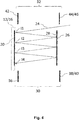
- the first auxiliary reflective element 30 comprises a first mirror 36 arranged laterally next to a first side of the disk laser 16 in a top view on the optical module 14 in the direction of the disk laser 16.
- the first auxiliary reflective element 30 comprises a second mirror 38 and a third mirror 40 arranged laterally next to a first side of the main reflective element 26 in a top view on the optical module 14 in the direction of the disk laser 16.
- the first mirror 36, the second mirror 38 and the third mirror 40 are arranged on a same side of the disk laser 16.
- the first mirror 36, the second mirror 38 and the third mirror 40 are arranged such that they allow redirecting the laser beam 24 from a line to a subsequent line as discussed for the embodiment according to figure 3 .
- redirecting of the laser beam 24 from a line to a subsequent line is performed in that the laser beam 24 is reflected from the disk laser 16 towards the second mirror 38 (tile 7 in figure 3 ) from which the laser beam is reflected towards the first mirror 36.
- the first mirror 36 reflects the laser beam towards the third mirror 40 (tile 8 in figure 3 ) which directs the laser beam towards the disk laser 16.
- the second auxiliary reflective element 32 comprises a fourth mirror 42, a fifth mirror 44 and a sixth mirror 46.
- the fourth mirror 42 is arranged laterally next to a second side of the disk laser 16 in a top view on the optical module 14 in the direction of the disk laser 16, wherein the first side of the disk laser 16 is opposite to the second side of the disk laser 16 with respect to the disk laser 16.
- the fifth mirror 44 and the sixth mirror 46 are arranged laterally next to a second side of the main reflective element 26 in a top view on the optical module 14 in the direction of the disk laser 16.
- the first side of the main reflective element 26 is opposite to the second side of the main reflective element 26 with respect to the main reflective element 16.
- the fourth mirror 42, the fifth mirror 44 and the sixth mirror 46 are arranged at a same side of the disk laser 16. As discussed above for the first mirror 36, the second mirror 38 and the third mirror 40, the fourth mirror 42, the fifth mirror 44 and the sixth mirror 46 are arranged such that they allow redirecting the laser beam 24 from a line to a subsequent line.
- the retroreflective mirror described in the embodiment of figure 3 it is possible to exactly adjust the mirrors allowing to adjust the scanning of the disk laser 16 with the laser beam 24.
- an optical module 14 allow to provide an optical module having a simple setup, i.e. the number of reflective elements is kept low which allows to provide an inexpensive realisation of the optical module.
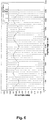
- the main reflective element 26 can be positioned close to the disk laser 16, for example 9cm. Hence, the distance the laser beam 24 travels during an amplifying pass can be kept short as shown in figure 6 whereby the quality of the laser beam 24 improves.
- Figure 6 shows on the abscissa the length of the way the laser beam 24 travels during an amplifying pass and on the ordinate the beam size of the laser beam 24.
- Figure 6 also shows in the X-direction at which length the laser beam impacts on the disk laser 16, the main reflective element 30, the first auxiliary reflective element 30 and the second auxiliary reflective element 32.
Landscapes
- Physics & Mathematics (AREA)
- Electromagnetism (AREA)
- Engineering & Computer Science (AREA)
- Plasma & Fusion (AREA)
- Optics & Photonics (AREA)
- Lasers (AREA)
Abstract
Description
- The invention relates to a method for amplifying a laser beam in a laser amplifier system, a laser amplifier system for amplifying a laser beam and an optical module for use in a laser amplifier system.
- In general, laser amplifier systems are used for amplifying a laser beam to achieve a certain output power of the laser beam. One exemplary approach for amplifying a laser beam involves using a disk laser as a laser active medium providing an excited area, i.e. a pump spot. The excited area and/or the pump spot is usually generated through a pump module, e.g. a laser diode, which excites the laser active medium to store energy within the laser active medium. Further, a laser beam generated by a source laser module is coupled into the laser amplifier system and the laser beam is reflected several times with a suitable optical arrangement to the same position of the pump spot by which the laser beam extracts the energy stored within the laser active medium. Known laser amplifying methods and laser amplifier systems use a laser beam having a beam size, i.e. the beam diameter, which substantially corresponds to the size of the pump spot, i.e. the diameter of the pump spot. For example, the laser beam may have a beam diameter of 8 mm and the pump spot may have a diameter of 9 mm. The number of repetitions the laser beam passes the laser active medium determines among others the level of the laser beam's amplification.
- However, exemplary systems have several drawbacks. For example, the optical arrangement reflecting the laser beam several times to the pump spot requires a complex arrangement of reflectors/mirrors resulting in a bulky and expensive optical arrangement. Further, the laser beam is required to travel a long distance (propagation length of the laser beam) until the laser beam has achieved the desired level of amplification which may cause stability issues of the laser beam and makes the laser beam sensitive to thermal turbulences degrading the performance of the laser beam. Furthermore, when using an exemplary laser amplifier for high energy/peak power applications, deteriorations of the laser beam quality increase with the laser beam's propagation length due to nonlinear optical effects.
- Thus, it is an objective of the present invention to provide a method for amplifying a laser beam, a laser amplifier system and an optical module for use in a laser amplifier system which provide a good and stable amplification of a laser beam, which allow a simple and inexpensive optical arrangement for reflecting the laser beam several times to a laser amplifier module, and which reduce the distance a laser beam has to travel though a laser amplifier system until the laser beam has achieved the desired level of amplification.
- Said objective is achieved by the subject matter of the independent claims. Preferred embodiments are defined in the dependent claims.
- An aspect of the invention relates to a method for amplifying a laser beam in a laser amplifier system including a laser amplifier module and an optical module, the method comprising generating an excited volume in a laser amplifier module so that a surface of the laser amplifier module facing the optical module includes an excited area. The method also comprises coupling the laser beam into the laser amplifier system, conducting a first amplifying pass by reflecting the laser beam multiple times between the optical module and the laser amplifier module. Each time the laser beam is reflected from the optical module to the laser amplifier module, the laser beam impacts on a respective impact area of the surface of the laser amplifier module. Further, the size of each impact area is smaller than the size of the excited area, and a subset of impact areas of all of the impact areas is located on distinct positions of and/or within the excited area.
- Advantageously, the invention enables the laser beam to extract energy from distinct positions of and/or within the excited area so that the laser beam is amplified every time the laser beam is reflected from the optical module to a position within the excited area. Further, the invention allows that the optical module is placed close to the laser amplifier module so that the distance the laser beam must travel between the optical module and the laser amplifier module during the first amplifying pass can be kept short. Consequently, the total length the laser beam travels from coupling the laser beam to the laser amplifier system, performing the first amplifying pass until the laser beam is decoupled from the laser amplifier system can be kept relatively short. Thus, the impact of thermal turbulences to the laser beam can be reduced.
- Preferably, the laser amplifier module may be a laser active medium such as a disk laser. Additionally, the laser amplifier system may comprise a pump module which pumps the laser active medium and/or the disk laser. By pumping the laser active medium and/or the disk laser, the excited volume is generated in the laser active medium. Further, a surface of the laser active medium and/or the disk laser may face the optical module and due to the excited volume of the laser active medium, said surface may include the excited area.
- Preferably, the laser beam is reflected between the optical module and the laser amplifier module such that the laser beam impacts at least two times on the laser amplifier module on a respective impact area within the excited area. Further, the subset of impact areas may comprise all the impact areas so that the all impact areas are located on distinct positions within the excited area. Thus, the laser beam can extract the energy from different locations of the excited medium for amplifying the laser beam.
- Further, the level of amplification of the laser beam is determined by the number of times the laser beam is reflected between the optical module and the laser amplifier module. In particular, the level of amplification of the laser beam is determined by the number of impact areas contained in the subset, i.e. the number of impact areas within the excited area. Preferably, the number of impact areas in the subset may be at least 10, more preferably at least 20. In a further embodiment, the number of impact areas in the subset may be at least 30, more preferably 40. Further, the level of amplification may be increased by increasing the size of the excited area that can be used for amplifying the laser beam at a given size of the impact area. Accordingly, the number of impact areas can be increased. Further, the maximum power intensity of the excited volume is limited so that the maximum power stored in the excited volume can be scaled by the size of the excited area.
- The size of an impact area generated by the laser beam on the surface of the laser amplifier module is substantially determined by the beam diameter and/or the beam size of the laser beam. The beam size may correspond to the expansion of the laser beam perpendicular to the axis of propagation of the laser beam. However, the laser beam may correspond to a Gaussian beam having a bell-shaped intensity curve perpendicular to the axis of propagation. Thus, in theory the laser beam would have an endless expansion perpendicular to the axis of propagation. For the present disclosure, it is considered that the beam size/diameter is finite. In particular, the beam size/diameter may correspond to a finite range of the intensity profile of the laser beam perpendicular to the axis of propagation of the laser beam. For example, the beam size and/or beam diameter and/or beam width may correspond to a range between two points in the intensity profile where the intensity is 1/e2 of the peak value in the intensity profile of the laser beam. Further, the excited area may have a flat-top intensity profile with sharp edges determining the size of the exited area. For example, the excited area is modelled with a high-super gaussian profile.
- Alternatively, the beam size and/or beam diameter and/or beam width may correspond to a full-width, half maximum (FWHM) range of the intensity profile of the laser beam, i.e. the range between the two points in the intensity profile at which the intensity is half the peak value of the intensity profile.
- Alternatively, the beam size and/or beam diameter and/or beam width may correspond to the definition according to ISO 11146, i.e., based on the 2nd of the intensity profile.
- Further, the laser beam may have a substantially circular cross-section in the direction of propagation. Hence, impact areas generated by the laser beam on the surface of the laser amplifier module may also have a substantially circular shape.
- Preferably, the impact areas included in the subset may at most partly overlap. That is, the centres of gravity of the respective impact areas included the subset are different. Thus, every time the laser beam impinges on the excited area, the laser beam may at least partially extract energy from the excited volume that has not been impinged by the laser beam before.
- Preferably, the impact areas of the subset are distributed evenly within the excited area. Advantageously, the even distribution of the impact areas allows a homogeneous extraction of the energy stored in the laser amplifier module. Further, it is possible to provide a simple arrangement of the optical module that allows the even distribution of the impact areas. Preferably, the impact areas are considered even distributed if the distance between adjacent impact areas are substantially the same throughout the subset of impact areas. Further, the distance between adjacent impact areas may be determined by the distance between the centre of gravity of said adjacent impact areas.
- Preferably, a centre of gravity of each impact area of the subset may be located on a different position of the excited area. The centre of gravity may correspond to the center of the substantially circular shaped impact area and may be determined by the peak value in the intensity profile of the laser beam.
- Preferably, the impact areas may be spaced apart from each other on the surface of the laser amplifier module and/or the excited area by at least 1 time the size of the impact area and/or by at least 1 time the size of the beam diameter, and preferably by at least 1,5 times the size of the impact area and/or by at least 1,5 times the size of the beam diameter. Advantageously, by maintaining a space between the impact areas, diffraction losses can be avoided.
- Preferably, a ratio between the size of the excited area and the size of each of the impact areas is substantially at least


- Further, the ratio of 4:1 between the size of the excited area and the size of each of the impact areas allows to have exactly two impact areas on an excited area having a substantially circular shape. In particular, the radius of the excited area having a substantially circular shape may be 2 times of the radius of the impact area.
- Accordingly, the ratio between the size of the excited area and the impact area may be further increased to allow the arrangement of more than two non-overlapping impact areas on the excited area allowing to reach a higher level of amplification of the laser beam. Thus, the ratio needs to be chosen dependent on the required level of laser beam amplification.
- Preferably, the size of the excited area is substantially at least

- Preferably, the impact areas of the surface of the laser amplifier module are successively created in a temporal order and wherein a first number of the impact areas is successively created in a first direction on the surface of the laser amplifier module and a second number of the impact areas is successively created in a second direction on the surface of the laser amplifier module. Thus, in a top view on the excited area the excited area is scanned line wise with the laser beam. That is, the first number of impact areas created along the first direction may correspond to a first line scanned by the laser beam and the second number of the impact areas created along the second direction may correspond to a second line scanned by the laser beam. Preferably, the first direction and second direction may be parallel but opposite to each other. Further, the first direction and second direction may be parallel to the surface of the laser amplifier module.
- Preferably, the number of impact areas created in the first direction may at least be two. Further, the number of impact areas created in the second direction may at least be two. The excited area and/or the surface of the laser amplifier module may include more than two lines scanned by the laser beam, wherein the first line and each second subsequent line are scanned in the first direction and the second line and each second subsequent line are scanned in the second direction. Further, the impact areas per line may be more than two. With the proposed line by line scanning, it is possible to scan substantially the complete excited area with the laser beam to extract the energy stored within the laser amplifier module. Further, it is possible to increase the excited area and consequently the amount of stored energy in the laser amplifier module without increasing the energy density within the laser amplifier module which otherwise would cause warming of the laser amplifier module. It is preferably to reduce warming of the laser amplifier module in order to avoid a decrease of the gain cross section.
- Preferably, the last created impact area of the first number of impact areas is the predecessor of the first created impact area of the second number of impact areas.
- Preferably, the method may further comprise the steps of, after completing the first amplifying pass, conducting a second amplifying pass by reflecting the laser beam multiple times between the optical module and the laser amplifier module, wherein each time the laser beam is reflected from the optical module to the laser amplifier module, the laser beam impacts on a second pass impact area of the surface of the laser amplifier module. The second pass impact area may be located between two successive impact areas of the first amplifying pass. Advantageously, the second amplifying pass allows to scan the excited area a second time with the laser beam to further increase the level of amplification. Further, the second pass impact areas are also different to the impact areas of the first amplifying pass leading allowing to extract energy from positions on the laser amplifier module and/or excited area that have not been scanned with the laser beam during the first amplifying pass. Thus, the energy extraction from the laser amplifier system is maximized.
- The generating an excited volume may include generating the excited area having a substantially circular shape. Preferably, the excited area may have a substantially rectangular shape. The rectangular shape is advantageous as it allows a higher density of impact areas per size of the excited area compared to an excited area having the substantially circular shape.
- A further aspect of the invention relates to a laser amplifier system for amplifying a laser beam, the system comprising: a laser amplifier module and an optical module, wherein the laser amplifier module includes an excited volume having a surface facing the optical module, the surface facing the optical module provides an excited area. The optical module is configured to conduct a first amplifying pass of the laser beam and comprises a reflective element configured to reflect a laser beam coupled into the laser amplifier system multiple times between the reflective element and the laser amplifier module, each time the laser beam is reflected from the reflective element to the laser amplifier module, the laser beam impacts on a respective impact area of the surface of the laser amplifier module. The size of each impact area is smaller than the size of the excited area, and a subset of impact areas of all of the impact areas is located on distinct positions of and/or within the excited area.
- Further, the laser amplifier system may be configured to enable the above described method. Specifically, the laser amplifier module may include a laser active medium such as a disk laser providing the excited volume and the excited area as described above. The reflective element may include a main reflective element, for example a mirror, having a reflective surface which faces the surface of the disk laser and the excited area of the disk laser. In particular, the main reflective element may have a reflective surface facing the surface of the laser amplifier module. Thus, the optical module and the laser amplifier module may be optically coupled. In particular, the main reflective element may be arranged with respect to the laser amplifier module and/or disk laser such that the laser beam can travel between the surface of the laser amplifier module and/or disk laser and the reflective surface of the main reflective element. Preferably, the main reflective element may be arranged with respect to the laser amplifier module and/or disk laser such that the laser beam can travel between the excited area of the laser amplifier module and/or disk laser and the reflective surface of the main reflective element. Preferably, no further elements are arranged between the main reflective element and the laser amplifier system and/or disk laser. Further, a perpendicular in the centre of the excited area may be parallel to a perpendicular in the centre of the main reflective element. Preferably, both perpendiculars may coincide.
- Preferably, the reflective element is configured to create the impact areas of the surface of the laser amplifier module successively in a temporal order, and wherein a first number of the impact areas is successively created in a first direction on the surface of the laser amplifier module and a second number of the impact areas is successively created in a second direction on the surface of the laser amplifier module. Thus, the reflective element enables the above described line wise scanning of the excited area.
- Preferably, the reflective element of the optical module may further comprise an auxiliary reflective element configured to receive the laser beam from the last impact area of the first number of impact areas to reflect the laser beam towards the laser amplifier module and/or disk laser to create the first impact area of the second number of impact areas. That is, the auxiliary reflective element may allow the laser beam to translate from the first line to the second line. With other words, the auxiliary reflective element redirects the laser beam from the last impact area of the first number of impact areas to the first impact area of the second number. For example, the auxiliary reflective element may be provided as a pair of mirrors or as a retroreflective mirror. Further, the optical module may be configured to distribute the impact areas of the subset evenly within the excited area as described above. For example, the reflective surface of the main reflective element may have a substantially planar surface facing the disk laser and/or the excited area.
- A further aspect of the invention relates to an optical module for use in a laser amplifier system including a laser amplifier module, wherein the laser amplifier includes an excited volume having a surface facing the optical module, the surface facing the optical module providing an excited area. The optical module comprises a reflective element configured to reflect a laser beam coupled into the laser amplifier system multiple times between the reflective element and the laser amplifier module, each time the laser beam is reflected from the reflective element to the laser amplifier module, the laser beam impacts on a respective impact area of the surface of the laser amplifier module, wherein the size of each impact area is smaller than the size of the excited area, and wherein a subset of impact areas of all the impact areas is located on distinct positions of and/or within the excited area.
- The optical module may be further configured as discussed above. In particular, the optical module may be optically couplable to the laser amplifier module. The above aspects may be applicable for continuous wave (cw) laser beams and pulsed laser beams, e.g., ultrashort pulse laser beams. The to be amplified laser beam may be generated by a seed laser module. The seed laser module may generate the laser beam as a continuous wave laser beam or ultrashort pulse laser beam. The generated laser beam may be coupled in the laser amplifier system. For example, the generated laser beam may be directed from the seed laser module towards the laser amplifier module from where the laser beam is reflected to the optical module. The seed laser module may be provided as part of the laser amplifier system or may be provided separate from the laser amplifier system.
- These and other objects, features and advantages of the present invention will become more apparent upon reading of the following detailed description of preferred embodiments and accompanying drawings. It should be understood that even though embodiments are separately described, single features thereof may be combined to additional embodiments.
-
Figure 1 depicts an arrangement of a laser amplifier system according to the present disclosure. -
Figure 2 depicts an example of a first amplifying pass of a laser beam. -
Figure 3 depicts an embodiment for scanning of a laser amplifier module with a laser beam. -
Figure 4 and5 depicts a further embodiment for scanning of a laser amplifier module with a laser beam. -
Figure 6 depicts a diagram showing the beam width of the laser beam dependent on the propagation distance of the laser beam. -
Figure 1 depicts an embodiment of alaser amplifier system 10 according to the present disclosure. Thelaser amplifier system 10 comprises alaser amplifier module 12 which is optically coupled and/or coupleable with anoptical module 14 so that alaser beam 24 can be reflected between thelaser amplifier module 12 and theoptical module 14. Preferably, thelaser amplifier module 12 is provided as adisk laser 16 having a substantially disk-shaped laser active medium. Apump module 18 which may be part of thelaser amplifier system 10 or provided separate to thelaser amplifier system 10 is configured to pump and/or excite thelaser amplifier module 12 to create an excited volume in thedisk laser 16. Hence, asurface 19 of thedisk laser 16 facing theoptical module 14 provides anexcited area 20. In the present disclosure, the term "excited area" may also be referred to as pump spot and is denoted by the same reference sign used for theexcited area 20. - Further, a
seed laser module 22 which may be part of thelaser amplifier system 10 or provided separate to thelaser amplifier system 10 generates a (seed)laser beam 24 that is amplified by thelaser amplifier system 10. For amplifying thelaser beam 24, thelaser beam 24 is coupled into thelaser amplifier system 10 and reflected multiple times between thelaser amplifier module 12 and theoptical module 14. Specifically, in a first amplifying pass thelaser beam 24 is reflected multiple times between theoptical module 14 and thelaser amplifier module 12. Each time thelaser beam 24 is reflected from theoptical module 14 to thelaser amplifier module 12, thelaser beam 24 impacts on a respective impact area 11-14 on thepump spot 20 and/or on thesurface 19 of the disk-laser 16. Further, with every impact of thelaser beam 24 on and/or within theexcited area 20, thelaser beam 24 extracts some of the energy stored in thedisk laser 16 by which thelaser beam 24 is amplified. - According to the present disclosure, the size of each impact area 11-14 is substantially smaller than the size of the excited area/
pump spot 20 and a subset of impact areas of all of the impact areas is located on distinct positions of and/or within the excited area/pump spot 20. Thus, thelaser beam 24 extracts some of the energy stored in thedisk laser 16 from different positions of the excited volume. As discussed above, the size of the impact area 11-14 is determined by the beam size/beam width/beam diameter of thelaser beam 24. In the context of the present disclosure, the beam width/size/diameter of thelaser beam 24 may for example correspond to a range between two points in the intensity profile of the laser beam perpendicular to the propagation direction of the laser beam, where the intensity is 1/e2 of the peak value in the intensity profile of the laser beam. Alternatively, the beam size and/or beam diameter and/or beam width may correspond to a full-width, half maximum (FWHM) range of the intensity profile of thelaser beam 24, i.e. the range between the two points in the intensity profile at which the intensity is half the peak value of the intensity profile. Thus, for the present disclosure, the beam width/size/diameter of thelaser beam 24 is considered to be finite. - The
optical module 14 comprises a mainreflective element 26, for example a mirror, which is arranged opposite to thedisk laser 16 such that the mainreflective element 26 faces thesurface 19 of the disk laser and/or thepump spot 20. Further, the mainreflective element 26 has a substantially planarreflective surface 28 facing thedisk laser 16 and/or thepump spot 20 such that thelaser beam 24 may be reflected between thereflective surface 28 and thedisk laser 16. Further, theoptical module 14 may comprise at least one auxiliary reflective element, e.g. first auxiliaryreflective element 30 and second auxiliaryreflective element 32, which are configured to redirect thelaser beam 24 as further explained below. -
Figure 2 depicts an example of the first amplifying pass for amplifying thelaser beam 24. To simplify the presentation,figure 2 merely depicts thedisk laser 16 and the impact areas 11-14 generated on and/or with thepump spot 20 when thelaser beam 24 impacts on thedisk laser 16. As shown infigure 2 , the size of each of the impact areas 11-14 is substantially smaller than the size of thepump spot 20. With other words, the size of thepump spot 20 is substantially larger than the size of each of the impact areas I1-I4.Figure 2 shows that all impact areas 11-14 are positioned within the excited area. Thus, impact areas 11-14 are included in the subset of impact areas. Preferably, the size of thepump spot 20 is substantially at least
- Further, from each impact area 11-14 within the excited area, the
laser beam 24 may extract some of the energy stored in thedisk laser 16. In order to achieve the desired level of amplification of thelaser beam 24, theoptical module 14 is configured such that thelaser beam 24 can scan a plurality of distinct positions within theexcited area 20, wherein at each position an impact area is created. Further, the impact areas 11-14 are distinct from each other and at most partially overlap with each other within theexcited area 20. Preferably, the impact areas 11-14 do not overlap. Hence, from each of the impact areas I1-I4 thelaser beam 24 may extract some energy of the energy stored in thedisk laser 16, wherein the impact areas 11-14 have not been scanned earlier by thelaser beam 24 during the first amplifying pass. - Further, the impact areas 11-14 may be arranged such on and/or within the
pump spot 20, that adjacent impact areas, forexample impact area 11 andimpact area 12 are spaced apart from each other by at least 1 to 1.5 times the size of an impact area. Specifically, the minimum distance between the boundaries of said impact areas are spaced apart from each other by at least 1 to 1.5 times the beam size. Hence, diffraction losses can be reduced. -
Figure 3 schematically shows a configuration of anoptical module 14 in a top view on theoptical module 14 in the direction of thedisk laser 16. Theoptical module 14 comprises a substantially rectangular mainreflective element 26. The mainreflective element 26 opposes thedisk laser 16 and thereflective surface 28 of the mainreflective element 26 faces thedisk laser 16 and/or theexcited area 20. Infigure 3 , the mainreflective element 26 may correspond to a substantially rectangular surface covering tiles 1-6-9-14. Further, theoptical module 14 may comprise the first auxiliaryreflective element 30 on a first side of the mainreflective element 26 and the second auxiliaryreflective element 32 on a second side of the mainreflective element 26 in a top view on theoptical module 14 in the direction of thedisk laser 16. Reflective surfaces of the first auxiliaryreflective element 30 and the second auxiliaryreflective element 32 may also face thedisk laser 16. Infigure 3 , the first auxiliaryreflective element 30 corresponds totiles reflective element 32 corresponds totiles optical module 14 where thelaser beam 24, which is reflected between theoptical module 14 and thedisk laser 16, impinges on theoptical module 14 when reflected from thedisk laser 16 towards theoptical module 14. - For conducting the first amplifying pass of the
laser beam 24, thelaser beam 24 is coupled into thelaser amplifier system 10 and directed towards thedisk laser 16, where thelaser beam 24 impacts at aninitial impact area 11. From theinitial impact area 11, thelaser beam 24 is reflected multiple times between thedisk laser 16 and theoptical module 14. In particular, thelaser beam 24 is reflected from theinitial impact area 11 to a first position on the mainreflective element 26 indicated bytile 1. Further, impact areas I2 - I47 on thedisk laser 14 are created in a temporal order wherein the first number of impact areas indicated by impact areas 11-17 is successively created in a first direction D1 on thedisk laser 16. At least some impact areas (13, 14 and 15) of the first number of impact areas is created within theexcited area 20. Further, the first auxiliaryreflective element 30 is configured to redirect the laser beam so that a second number of impact areas (I11-I13) is successively created in a second direction D2 on thedisk laser 16. The first direction D1 and second direction D2 extend parallel to theexcited area 20 and are parallel to each other. Further, the first direction D1 is opposite to the second direction D2. Hence, theoptical module 14 scans thedisk laser 16 line by line wherein the first auxiliaryreflective element 30 and the second auxiliaryreflective element 32 redirects thelaser beam 14 to the different lines scanned by theoptical module 14. For example, the second auxiliaryreflective element 32 may redirect thelaser beam 24 from the second line indicated bytiles 8 to 15 to a third line indicated by tiles 16-23. - The first auxiliary
reflective element 30 and the second auxiliaryreflective element 32 may be provided as retroreflectors, for example as a mirror pair or triple mirror, wherein a line lying on the centre line CL of the first auxiliaryreflective element 30 extends through the centre of thepump spot 20 in a top view on theoptical module 14 in the direction of thedisk laser 16. Further, the first auxiliaryreflective element 30 is tilted towards the pump spot 20 (seefigure 1 ) so that the first auxiliaryreflective element 30 allows redirecting thelaser beam 24 from the first line to the second line. The centre line of the second auxiliaryreflective element 32 may be shifted by a half line towards the second line allowing to redirect thelaser beam 24 from the second line indicated by tiles 8-15 to the third line indicated by tiles 16-23. Further, the second auxiliaryreflective element 32 may also be tilted towards thepump spot 20. The above pattern of scanning line by line is repeated until thelaser beam 24 impacts on thelast impact area 147 from where thelaser beam 24 is reflected towards theoptical module 14, in particular towards the second auxiliaryreflective element 32. However, the second auxiliaryreflective element 32 may have agap 34 allowing decoupling thelaser beam 24 from thelaser amplifier system 10 when the laser beam is reflected fromimpact area 147 towards the second auxiliaryreflective element 32. - Instead of providing
gap 34 in the second auxiliaryreflective element 32, the second auxiliaryreflective element 32 may be configured to rotate the polarization of thelaser beam 24 and to reflect thelaser beam 24 back to thedisk laser 16 to conduct a second amplifying pass. By the second amplifying pass, thelaser beam 24 traverses the pattern of the first amplifying pass backwards resulting in an additional amplification of thelaser beam 24. - In a further embodiment explained with reference to
figures 4 and5 , the first auxiliaryreflective element 30 and the second auxiliaryreflective element 32 are not provided as retroreflectors. Instead, the first auxiliaryreflective element 30 comprises afirst mirror 36 arranged laterally next to a first side of thedisk laser 16 in a top view on theoptical module 14 in the direction of thedisk laser 16. Further, the first auxiliaryreflective element 30 comprises asecond mirror 38 and athird mirror 40 arranged laterally next to a first side of the mainreflective element 26 in a top view on theoptical module 14 in the direction of thedisk laser 16. Further, thefirst mirror 36, thesecond mirror 38 and thethird mirror 40 are arranged on a same side of thedisk laser 16. Thefirst mirror 36, thesecond mirror 38 and thethird mirror 40 are arranged such that they allow redirecting thelaser beam 24 from a line to a subsequent line as discussed for the embodiment according tofigure 3 . In particular, redirecting of thelaser beam 24 from a line to a subsequent line is performed in that thelaser beam 24 is reflected from thedisk laser 16 towards the second mirror 38 (tile 7 infigure 3 ) from which the laser beam is reflected towards thefirst mirror 36. Afterwards, thefirst mirror 36 reflects the laser beam towards the third mirror 40 (tile 8 infigure 3 ) which directs the laser beam towards thedisk laser 16. - In the same manner, the second auxiliary
reflective element 32 comprises afourth mirror 42, afifth mirror 44 and asixth mirror 46. Thefourth mirror 42 is arranged laterally next to a second side of thedisk laser 16 in a top view on theoptical module 14 in the direction of thedisk laser 16, wherein the first side of thedisk laser 16 is opposite to the second side of thedisk laser 16 with respect to thedisk laser 16. Thefifth mirror 44 and thesixth mirror 46 are arranged laterally next to a second side of the mainreflective element 26 in a top view on theoptical module 14 in the direction of thedisk laser 16. The first side of the mainreflective element 26 is opposite to the second side of the mainreflective element 26 with respect to the mainreflective element 16. Further, thefourth mirror 42, thefifth mirror 44 and thesixth mirror 46 are arranged at a same side of thedisk laser 16. As discussed above for thefirst mirror 36, thesecond mirror 38 and thethird mirror 40, thefourth mirror 42, thefifth mirror 44 and thesixth mirror 46 are arranged such that they allow redirecting thelaser beam 24 from a line to a subsequent line. By providing three single mirrors as compared to the retroreflective mirror described in the embodiment offigure 3 , it is possible to exactly adjust the mirrors allowing to adjust the scanning of thedisk laser 16 with thelaser beam 24. - Further, the above configurations of an
optical module 14 allow to provide an optical module having a simple setup, i.e. the number of reflective elements is kept low which allows to provide an inexpensive realisation of the optical module. Additionally, the mainreflective element 26 can be positioned close to thedisk laser 16, for example 9cm. Hence, the distance thelaser beam 24 travels during an amplifying pass can be kept short as shown infigure 6 whereby the quality of thelaser beam 24 improves. -
Figure 6 shows on the abscissa the length of the way thelaser beam 24 travels during an amplifying pass and on the ordinate the beam size of thelaser beam 24.Figure 6 also shows in the X-direction at which length the laser beam impacts on thedisk laser 16, the mainreflective element 30, the first auxiliaryreflective element 30 and the second auxiliaryreflective element 32. -
- 10
- laser amplifier system
- 12
- laser amplifier module
- 14
- optical module
- 16
- disk laser
- 18
- pump module
- 19
- surface
- 20
- excited area/pump spot
- 22
- seed laser module
- 24
- laser beam
- 26
- main reflective element
- 28
- reflective surface
- 30
- first auxiliary reflective element
- 32
- second auxiliary reflective element
- 34
- gap
- 36
- first mirror
- 38
- second mirror
- 40
- third mirror
- 42
- fourth mirror
- 44
- fifth mirror
- 46
- sixth mirror
- CL
- centre line of first auxiliary reflective element
- D1
- first direction
- D2
- second direction
- 11-147
- impact areas
Claims (15)
- Method for amplifying a laser beam in a laser amplifier system (10) including a laser amplifier module (12) and an optical module (14), the method comprising:- generating an excited volume in a laser amplifier module (12) so that a surface (19) of the laser amplifier module (12) facing the optical module (14) includes an excited area (20);- coupling the laser beam (24) into the laser amplifier system (10);- conducting a first amplifying pass by reflecting the laser beam (24) multiple times between the optical module (14) and the laser amplifier module (12), wherein each time the laser beam (24) is reflected from the optical module (14) to the laser amplifier module (14), the laser beam (14) impacts on a respective impact area (I2-I47) of the surface (19) of the laser amplifier module (12),wherein the size of each impact area (I2-I47) is smaller than the size of the excited area (20), and
wherein a subset of impact areas of all of the impact areas is located on distinct positions of the excited area (20). - The method of claim 1, wherein the size of the impact area is determined by the beam diameter of the laser beam (24).
- The method of claim 1 or 2, wherein the impact areas included in the subset at most partly overlap.
- The method of any one of the preceding claims, wherein the impact areas of the subset are distributed evenly within the excited area (20).
- The method of any one of the preceding claims, wherein a centre of gravity of each impact area of the subset is located on a different position of the excited area (20).
- The method of any one of the preceding claims, wherein the impact areas (I2-I47) are spaced apart from each other on the surface (19) of the laser amplifier module by at least 1 time the size of the impact area and preferably by at least 1,5 time the size of the impact area.
- The method of any one of the preceding claims, wherein a ratio between the size of the excited area (20) and the size of each of the impact areas is at least


- The method of any one of the preceding claims, wherein the impact areas on the surface (19) of the laser amplifier module are successively created in a temporal order and wherein a first number of the impact areas is successively created in a first direction (D1) on the surface (19) of the laser amplifier module (12) and a second number of the impact areas is successively created in a second direction (D2) on the surface of the laser amplifier module (12).
- The method of claim 8, wherein the last created impact area of the first number of impact areas is the predecessor of the first created impact area of the second number of impact areas; and wherein optionally the first direction (D1) is opposite to the second direction (D2).
- The method according to any one of the preceding claims, wherein the generating an excited volume includes generating the excited area (20) having a substantially circular shape or preferably a substantially rectangular shape.
- A laser amplifier system (10) for amplifying a laser beam (24), the system comprising:- a laser amplifier module (12); and- an optical module (14);wherein the laser amplifier module (12) includes an excited volume having a surface (19) facing the optical module (14), the surface (19) facing the optical module (14) providing an excited area (20);
wherein the optical module (14) is configured to conduct a first amplifying pass of the laser beam (24), and wherein the optical module (14) comprises a reflective element (26) configured to reflect a laser beam (24) coupled into the laser amplifier system (10) multiple times between the reflective element (26) and the laser amplifier module (12), each time the laser beam is reflected from the reflective element (26) to the laser amplifier module (12), the laser beam (24) impacts on a respective impact area (I2-I47) of the surface (19) of the laser amplifier module (12),
wherein the size of each impact area is smaller than the size of the excited area (20), and
wherein a subset of impact areas of all of the impact areas is located on distinct positions of the excited area (20). - The laser amplifier system (10) of claim 11, wherein the laser amplifier module (12) includes a disk laser (16); and/or
wherein the reflective element (26) is configured to distribute the impact areas of the subset evenly within the excited area. - The laser amplifier system (10) of claim 11 or 12, wherein the reflective element (26) is configured to create the impact areas of the surface of the laser amplifier module successively in a temporal order, and wherein a first number of the impact areas is successively created in a first direction (D1) on the surface (19) of the laser amplifier module (12) and a second number of the impact areas is successively created in a second direction (D2) on the surface of the laser amplifier module (12).
- The laser amplifier system (10) of claim 13, wherein the optical module (14) further comprises an auxiliary reflective element configured to receive the laser beam from the last impact area of the first number of impact areas to reflect the laser beam towards the laser amplifier (14) module to create the first impact area of the second number of impact areas.
- An optical module (14) for use in a laser amplifier system (10) including a laser amplifier module (12), wherein the laser amplifier module (12) includes an excited volume having a surface (19) for facing the optical module (12), the surface facing the optical module providing an excited area (20), the optical module (14) comprising:a reflective element (26) configured to reflect a laser beam (24) coupled into the laser amplifier system (10) multiple times between the reflective element (26) and the laser amplifier module (12), each time the laser beam (24) is reflected from the reflective element (26) to the laser amplifier module (12), the laser beam (24) impacts on a respective impact area (I2-I47) of the surface (19) of the laser amplifier module (12),wherein the size of each impact area is smaller than the size of the excited area (20),wherein a subset of impact areas of all the impact areas is located on distinct positions of the excited area (20).
Priority Applications (2)
| Application Number | Priority Date | Filing Date | Title |
|---|---|---|---|
| LTEP19209371.4T LT3823111T (en) | 2019-11-15 | 2019-11-15 | Method for amplifying a laser beam, laser amplifier system and optical module for use in a laser amplifier system |
| EP19209371.4A EP3823111B1 (en) | 2019-11-15 | 2019-11-15 | Method for amplifying a laser beam, laser amplifier system and optical module for use in a laser amplifier system |
Applications Claiming Priority (1)
| Application Number | Priority Date | Filing Date | Title |
|---|---|---|---|
| EP19209371.4A EP3823111B1 (en) | 2019-11-15 | 2019-11-15 | Method for amplifying a laser beam, laser amplifier system and optical module for use in a laser amplifier system |
Publications (2)
| Publication Number | Publication Date |
|---|---|
| EP3823111A1 true EP3823111A1 (en) | 2021-05-19 |
| EP3823111B1 EP3823111B1 (en) | 2023-06-07 |
Family
ID=68583147
Family Applications (1)
| Application Number | Title | Priority Date | Filing Date |
|---|---|---|---|
| EP19209371.4A Active EP3823111B1 (en) | 2019-11-15 | 2019-11-15 | Method for amplifying a laser beam, laser amplifier system and optical module for use in a laser amplifier system |
Country Status (2)
| Country | Link |
|---|---|
| EP (1) | EP3823111B1 (en) |
| LT (1) | LT3823111T (en) |
Citations (3)
| Publication number | Priority date | Publication date | Assignee | Title |
|---|---|---|---|---|
| US5546222A (en) * | 1992-11-18 | 1996-08-13 | Lightwave Electronics Corporation | Multi-pass light amplifier |
| US20050195474A1 (en) * | 2002-01-15 | 2005-09-08 | Jds Uniphase Corporation | Three -dimensional optical amplifier structure |
| US20060153257A1 (en) * | 2005-01-10 | 2006-07-13 | Kresimir Franjic | Laser amplifiers with high gain and small thermal aberrations |
-
2019
- 2019-11-15 LT LTEP19209371.4T patent/LT3823111T/en unknown
- 2019-11-15 EP EP19209371.4A patent/EP3823111B1/en active Active
Patent Citations (3)
| Publication number | Priority date | Publication date | Assignee | Title |
|---|---|---|---|---|
| US5546222A (en) * | 1992-11-18 | 1996-08-13 | Lightwave Electronics Corporation | Multi-pass light amplifier |
| US20050195474A1 (en) * | 2002-01-15 | 2005-09-08 | Jds Uniphase Corporation | Three -dimensional optical amplifier structure |
| US20060153257A1 (en) * | 2005-01-10 | 2006-07-13 | Kresimir Franjic | Laser amplifiers with high gain and small thermal aberrations |
Non-Patent Citations (2)
| Title |
|---|
| NEGEL JAN-PHILIPP ET AL: "Thin-disk multipass amplifier for ultrashort laser pulses with kilowatt average output power and mJ pulse energies", PROCEEDINGS OF SPIE/ IS & T,, vol. 9135, 1 May 2014 (2014-05-01), pages 91351D - 91351D, XP060030282, ISBN: 978-1-62841-730-2, DOI: 10.1117/12.2053964 * |
| OLSON T E ET AL: "Multipass diode-pumped Nd:YAG optical amplifiers at 1.06 micro-m and 1.32 micro-m", IEEE PHOTONICS TECHNOLOGY LETTERS, IEEE SERVICE CENTER, PISCATAWAY, NJ, US, vol. 6, no. 5, May 1994 (1994-05-01), pages 605 - 608, XP011411343, ISSN: 1041-1135, DOI: 10.1109/68.285555 * |
Also Published As
| Publication number | Publication date |
|---|---|
| LT3823111T (en) | 2023-09-11 |
| EP3823111B1 (en) | 2023-06-07 |
Similar Documents
| Publication | Publication Date | Title |
|---|---|---|
| Laabs et al. | Excitation of Hermite Gaussian modes in end-pumped solid-state lasers via off-axis pumping | |
| TWI586058B (en) | High power femtosecond laser with variable repetition rate | |
| US6377599B1 (en) | Focusability enhancing optic for a laser diode | |
| US20070229939A1 (en) | Method and apparatus for spectral-beam combining of fiber-amplified laser beams using high-efficiency dielectric diffractive gratings | |
| JP2008522409A (en) | High gain diode pumped laser amplifier. | |
| EP0772901A1 (en) | High-power optical fiber amplifier or laser device | |
| US20030218795A1 (en) | Optical chirped beam amplification and propagation | |
| EP3048678A1 (en) | Laser beam amplification by homogenous pumping of an amplification medium | |
| JP2004515052A (en) | Phase control mechanism of coherent fiber amplifier array | |
| CN106410608A (en) | Laser array and laser beam combining device | |
| US11777272B2 (en) | Multiplexing fiber amplified waveforms | |
| US10411435B2 (en) | Dual-axis adaptive optic (AO) system for high-power lasers | |
| EP0663606B1 (en) | Laser beam scanning radiating apparatus | |
| US9337606B2 (en) | Spectral-temporal multiplexer for pulsed fiber scaling | |
| US20100002743A1 (en) | Laser focusing through turbulent medium | |
| EP0592499A1 (en) | Slab laser resonators | |
| US11269136B1 (en) | Hollow core optical fiber array launcher with sealed lens block | |
| EP0452838A1 (en) | Optical phase conjugation apparatus including light pipe for multiple beam combination | |
| EP0847115B1 (en) | Light amplifier with two incident beams | |
| Goodno et al. | Engineering of Coherently Combined, High‐Power Laser Systems | |
| EP3823111B1 (en) | Method for amplifying a laser beam, laser amplifier system and optical module for use in a laser amplifier system | |
| US9728932B2 (en) | Fiber coupled modular laser system | |
| US7280577B2 (en) | Pumping method for laser equipment | |
| CN117913632B (en) | A slab laser amplifier with multiple spherical aberration optimization | |
| US20160064893A1 (en) | Device For Reducing Optical Feedback Into Laser Amplifier |
Legal Events
| Date | Code | Title | Description |
|---|---|---|---|
| PUAI | Public reference made under article 153(3) epc to a published international application that has entered the european phase |
Free format text: ORIGINAL CODE: 0009012 |
|
| STAA | Information on the status of an ep patent application or granted ep patent |
Free format text: STATUS: THE APPLICATION HAS BEEN PUBLISHED |
|
| AK | Designated contracting states |
Kind code of ref document: A1 Designated state(s): AL AT BE BG CH CY CZ DE DK EE ES FI FR GB GR HR HU IE IS IT LI LT LU LV MC MK MT NL NO PL PT RO RS SE SI SK SM TR |
|
| STAA | Information on the status of an ep patent application or granted ep patent |
Free format text: STATUS: REQUEST FOR EXAMINATION WAS MADE |
|
| 17P | Request for examination filed |
Effective date: 20211118 |
|
| RBV | Designated contracting states (corrected) |
Designated state(s): AL AT BE BG CH CY CZ DE DK EE ES FI FR GB GR HR HU IE IS IT LI LT LU LV MC MK MT NL NO PL PT RO RS SE SI SK SM TR |
|
| GRAP | Despatch of communication of intention to grant a patent |
Free format text: ORIGINAL CODE: EPIDOSNIGR1 |
|
| STAA | Information on the status of an ep patent application or granted ep patent |
Free format text: STATUS: GRANT OF PATENT IS INTENDED |
|
| RIC1 | Information provided on ipc code assigned before grant |
Ipc: H01S 3/06 20060101ALN20220531BHEP Ipc: H01S 3/091 20060101ALI20220531BHEP Ipc: H01S 3/00 20060101ALI20220531BHEP Ipc: H01S 3/23 20060101AFI20220531BHEP |
|
| RIC1 | Information provided on ipc code assigned before grant |
Ipc: H01S 3/06 20060101ALN20220610BHEP Ipc: H01S 3/091 20060101ALI20220610BHEP Ipc: H01S 3/00 20060101ALI20220610BHEP Ipc: H01S 3/23 20060101AFI20220610BHEP |
|
| INTG | Intention to grant announced |
Effective date: 20220704 |
|
| GRAJ | Information related to disapproval of communication of intention to grant by the applicant or resumption of examination proceedings by the epo deleted |
Free format text: ORIGINAL CODE: EPIDOSDIGR1 |
|
| STAA | Information on the status of an ep patent application or granted ep patent |
Free format text: STATUS: REQUEST FOR EXAMINATION WAS MADE |
|
| GRAP | Despatch of communication of intention to grant a patent |
Free format text: ORIGINAL CODE: EPIDOSNIGR1 |
|
| INTC | Intention to grant announced (deleted) | ||
| STAA | Information on the status of an ep patent application or granted ep patent |
Free format text: STATUS: GRANT OF PATENT IS INTENDED |
|
| RIC1 | Information provided on ipc code assigned before grant |
Ipc: H01S 3/06 20060101ALN20221129BHEP Ipc: H01S 3/091 20060101ALI20221129BHEP Ipc: H01S 3/00 20060101ALI20221129BHEP Ipc: H01S 3/23 20060101AFI20221129BHEP |
|
| INTG | Intention to grant announced |
Effective date: 20221215 |
|
| RIC1 | Information provided on ipc code assigned before grant |
Ipc: H01S 3/06 20060101ALN20221202BHEP Ipc: H01S 3/091 20060101ALI20221202BHEP Ipc: H01S 3/00 20060101ALI20221202BHEP Ipc: H01S 3/23 20060101AFI20221202BHEP |
|
| GRAS | Grant fee paid |
Free format text: ORIGINAL CODE: EPIDOSNIGR3 |
|
| GRAA | (expected) grant |
Free format text: ORIGINAL CODE: 0009210 |
|
| STAA | Information on the status of an ep patent application or granted ep patent |
Free format text: STATUS: THE PATENT HAS BEEN GRANTED |
|
| AK | Designated contracting states |
Kind code of ref document: B1 Designated state(s): AL AT BE BG CH CY CZ DE DK EE ES FI FR GB GR HR HU IE IS IT LI LT LU LV MC MK MT NL NO PL PT RO RS SE SI SK SM TR |
|
| REG | Reference to a national code |
Ref country code: GB Ref legal event code: FG4D |
|
| REG | Reference to a national code |
Ref country code: CH Ref legal event code: EP Ref country code: AT Ref legal event code: REF Ref document number: 1577746 Country of ref document: AT Kind code of ref document: T Effective date: 20230615 |
|
| REG | Reference to a national code |
Ref country code: DE Ref legal event code: R096 Ref document number: 602019029937 Country of ref document: DE |
|
| REG | Reference to a national code |
Ref country code: NL Ref legal event code: MP Effective date: 20230607 |
|
| PG25 | Lapsed in a contracting state [announced via postgrant information from national office to epo] |
Ref country code: SE Free format text: LAPSE BECAUSE OF FAILURE TO SUBMIT A TRANSLATION OF THE DESCRIPTION OR TO PAY THE FEE WITHIN THE PRESCRIBED TIME-LIMIT Effective date: 20230607 Ref country code: NO Free format text: LAPSE BECAUSE OF FAILURE TO SUBMIT A TRANSLATION OF THE DESCRIPTION OR TO PAY THE FEE WITHIN THE PRESCRIBED TIME-LIMIT Effective date: 20230907 Ref country code: ES Free format text: LAPSE BECAUSE OF FAILURE TO SUBMIT A TRANSLATION OF THE DESCRIPTION OR TO PAY THE FEE WITHIN THE PRESCRIBED TIME-LIMIT Effective date: 20230607 |
|
| REG | Reference to a national code |
Ref country code: AT Ref legal event code: MK05 Ref document number: 1577746 Country of ref document: AT Kind code of ref document: T Effective date: 20230607 |
|
| PG25 | Lapsed in a contracting state [announced via postgrant information from national office to epo] |
Ref country code: RS Free format text: LAPSE BECAUSE OF FAILURE TO SUBMIT A TRANSLATION OF THE DESCRIPTION OR TO PAY THE FEE WITHIN THE PRESCRIBED TIME-LIMIT Effective date: 20230607 Ref country code: NL Free format text: LAPSE BECAUSE OF FAILURE TO SUBMIT A TRANSLATION OF THE DESCRIPTION OR TO PAY THE FEE WITHIN THE PRESCRIBED TIME-LIMIT Effective date: 20230607 Ref country code: LV Free format text: LAPSE BECAUSE OF FAILURE TO SUBMIT A TRANSLATION OF THE DESCRIPTION OR TO PAY THE FEE WITHIN THE PRESCRIBED TIME-LIMIT Effective date: 20230607 Ref country code: HR Free format text: LAPSE BECAUSE OF FAILURE TO SUBMIT A TRANSLATION OF THE DESCRIPTION OR TO PAY THE FEE WITHIN THE PRESCRIBED TIME-LIMIT Effective date: 20230607 Ref country code: GR Free format text: LAPSE BECAUSE OF FAILURE TO SUBMIT A TRANSLATION OF THE DESCRIPTION OR TO PAY THE FEE WITHIN THE PRESCRIBED TIME-LIMIT Effective date: 20230908 |
|
| PG25 | Lapsed in a contracting state [announced via postgrant information from national office to epo] |
Ref country code: FI Free format text: LAPSE BECAUSE OF FAILURE TO SUBMIT A TRANSLATION OF THE DESCRIPTION OR TO PAY THE FEE WITHIN THE PRESCRIBED TIME-LIMIT Effective date: 20230607 |
|
| PG25 | Lapsed in a contracting state [announced via postgrant information from national office to epo] |
Ref country code: SK Free format text: LAPSE BECAUSE OF FAILURE TO SUBMIT A TRANSLATION OF THE DESCRIPTION OR TO PAY THE FEE WITHIN THE PRESCRIBED TIME-LIMIT Effective date: 20230607 |
|
| PG25 | Lapsed in a contracting state [announced via postgrant information from national office to epo] |
Ref country code: IS Free format text: LAPSE BECAUSE OF FAILURE TO SUBMIT A TRANSLATION OF THE DESCRIPTION OR TO PAY THE FEE WITHIN THE PRESCRIBED TIME-LIMIT Effective date: 20231007 |
|
| PG25 | Lapsed in a contracting state [announced via postgrant information from national office to epo] |
Ref country code: SM Free format text: LAPSE BECAUSE OF FAILURE TO SUBMIT A TRANSLATION OF THE DESCRIPTION OR TO PAY THE FEE WITHIN THE PRESCRIBED TIME-LIMIT Effective date: 20230607 Ref country code: SK Free format text: LAPSE BECAUSE OF FAILURE TO SUBMIT A TRANSLATION OF THE DESCRIPTION OR TO PAY THE FEE WITHIN THE PRESCRIBED TIME-LIMIT Effective date: 20230607 Ref country code: RO Free format text: LAPSE BECAUSE OF FAILURE TO SUBMIT A TRANSLATION OF THE DESCRIPTION OR TO PAY THE FEE WITHIN THE PRESCRIBED TIME-LIMIT Effective date: 20230607 Ref country code: PT Free format text: LAPSE BECAUSE OF FAILURE TO SUBMIT A TRANSLATION OF THE DESCRIPTION OR TO PAY THE FEE WITHIN THE PRESCRIBED TIME-LIMIT Effective date: 20231009 Ref country code: IS Free format text: LAPSE BECAUSE OF FAILURE TO SUBMIT A TRANSLATION OF THE DESCRIPTION OR TO PAY THE FEE WITHIN THE PRESCRIBED TIME-LIMIT Effective date: 20231007 Ref country code: EE Free format text: LAPSE BECAUSE OF FAILURE TO SUBMIT A TRANSLATION OF THE DESCRIPTION OR TO PAY THE FEE WITHIN THE PRESCRIBED TIME-LIMIT Effective date: 20230607 Ref country code: CZ Free format text: LAPSE BECAUSE OF FAILURE TO SUBMIT A TRANSLATION OF THE DESCRIPTION OR TO PAY THE FEE WITHIN THE PRESCRIBED TIME-LIMIT Effective date: 20230607 Ref country code: AT Free format text: LAPSE BECAUSE OF FAILURE TO SUBMIT A TRANSLATION OF THE DESCRIPTION OR TO PAY THE FEE WITHIN THE PRESCRIBED TIME-LIMIT Effective date: 20230607 |
|
| PG25 | Lapsed in a contracting state [announced via postgrant information from national office to epo] |
Ref country code: PL Free format text: LAPSE BECAUSE OF FAILURE TO SUBMIT A TRANSLATION OF THE DESCRIPTION OR TO PAY THE FEE WITHIN THE PRESCRIBED TIME-LIMIT Effective date: 20230607 |
|
| REG | Reference to a national code |
Ref country code: DE Ref legal event code: R097 Ref document number: 602019029937 Country of ref document: DE |
|
| PLBE | No opposition filed within time limit |
Free format text: ORIGINAL CODE: 0009261 |
|
| STAA | Information on the status of an ep patent application or granted ep patent |
Free format text: STATUS: NO OPPOSITION FILED WITHIN TIME LIMIT |
|
| PG25 | Lapsed in a contracting state [announced via postgrant information from national office to epo] |
Ref country code: DK Free format text: LAPSE BECAUSE OF FAILURE TO SUBMIT A TRANSLATION OF THE DESCRIPTION OR TO PAY THE FEE WITHIN THE PRESCRIBED TIME-LIMIT Effective date: 20230607 |
|
| PG25 | Lapsed in a contracting state [announced via postgrant information from national office to epo] |
Ref country code: SI Free format text: LAPSE BECAUSE OF FAILURE TO SUBMIT A TRANSLATION OF THE DESCRIPTION OR TO PAY THE FEE WITHIN THE PRESCRIBED TIME-LIMIT Effective date: 20230607 |
|
| 26N | No opposition filed |
Effective date: 20240308 |
|
| PG25 | Lapsed in a contracting state [announced via postgrant information from national office to epo] |
Ref country code: SI Free format text: LAPSE BECAUSE OF FAILURE TO SUBMIT A TRANSLATION OF THE DESCRIPTION OR TO PAY THE FEE WITHIN THE PRESCRIBED TIME-LIMIT Effective date: 20230607 Ref country code: IT Free format text: LAPSE BECAUSE OF FAILURE TO SUBMIT A TRANSLATION OF THE DESCRIPTION OR TO PAY THE FEE WITHIN THE PRESCRIBED TIME-LIMIT Effective date: 20230607 |
|
| REG | Reference to a national code |
Ref country code: CH Ref legal event code: PL |
|
| PG25 | Lapsed in a contracting state [announced via postgrant information from national office to epo] |
Ref country code: MC Free format text: LAPSE BECAUSE OF FAILURE TO SUBMIT A TRANSLATION OF THE DESCRIPTION OR TO PAY THE FEE WITHIN THE PRESCRIBED TIME-LIMIT Effective date: 20230607 |
|
| PG25 | Lapsed in a contracting state [announced via postgrant information from national office to epo] |
Ref country code: LU Free format text: LAPSE BECAUSE OF NON-PAYMENT OF DUE FEES Effective date: 20231115 |
|
| PG25 | Lapsed in a contracting state [announced via postgrant information from national office to epo] |
Ref country code: CH Free format text: LAPSE BECAUSE OF NON-PAYMENT OF DUE FEES Effective date: 20231130 |
|
| GBPC | Gb: european patent ceased through non-payment of renewal fee |
Effective date: 20231115 |
|
| PG25 | Lapsed in a contracting state [announced via postgrant information from national office to epo] |
Ref country code: MC Free format text: LAPSE BECAUSE OF FAILURE TO SUBMIT A TRANSLATION OF THE DESCRIPTION OR TO PAY THE FEE WITHIN THE PRESCRIBED TIME-LIMIT Effective date: 20230607 Ref country code: LU Free format text: LAPSE BECAUSE OF NON-PAYMENT OF DUE FEES Effective date: 20231115 Ref country code: CH Free format text: LAPSE BECAUSE OF NON-PAYMENT OF DUE FEES Effective date: 20231130 |
|
| REG | Reference to a national code |
Ref country code: BE Ref legal event code: MM Effective date: 20231130 |
|
| REG | Reference to a national code |
Ref country code: IE Ref legal event code: MM4A |
|
| PG25 | Lapsed in a contracting state [announced via postgrant information from national office to epo] |
Ref country code: IE Free format text: LAPSE BECAUSE OF NON-PAYMENT OF DUE FEES Effective date: 20231115 |
|
| PG25 | Lapsed in a contracting state [announced via postgrant information from national office to epo] |
Ref country code: GB Free format text: LAPSE BECAUSE OF NON-PAYMENT OF DUE FEES Effective date: 20231115 |
|
| PG25 | Lapsed in a contracting state [announced via postgrant information from national office to epo] |
Ref country code: BE Free format text: LAPSE BECAUSE OF NON-PAYMENT OF DUE FEES Effective date: 20231130 |
|
| PG25 | Lapsed in a contracting state [announced via postgrant information from national office to epo] |
Ref country code: IE Free format text: LAPSE BECAUSE OF NON-PAYMENT OF DUE FEES Effective date: 20231115 Ref country code: GB Free format text: LAPSE BECAUSE OF NON-PAYMENT OF DUE FEES Effective date: 20231115 Ref country code: BE Free format text: LAPSE BECAUSE OF NON-PAYMENT OF DUE FEES Effective date: 20231130 |
|
| PG25 | Lapsed in a contracting state [announced via postgrant information from national office to epo] |
Ref country code: BG Free format text: LAPSE BECAUSE OF FAILURE TO SUBMIT A TRANSLATION OF THE DESCRIPTION OR TO PAY THE FEE WITHIN THE PRESCRIBED TIME-LIMIT Effective date: 20230607 |
|
| PG25 | Lapsed in a contracting state [announced via postgrant information from national office to epo] |
Ref country code: BG Free format text: LAPSE BECAUSE OF FAILURE TO SUBMIT A TRANSLATION OF THE DESCRIPTION OR TO PAY THE FEE WITHIN THE PRESCRIBED TIME-LIMIT Effective date: 20230607 |
|
| PG25 | Lapsed in a contracting state [announced via postgrant information from national office to epo] |
Ref country code: CY Free format text: LAPSE BECAUSE OF FAILURE TO SUBMIT A TRANSLATION OF THE DESCRIPTION OR TO PAY THE FEE WITHIN THE PRESCRIBED TIME-LIMIT; INVALID AB INITIO Effective date: 20191115 |
|
| PG25 | Lapsed in a contracting state [announced via postgrant information from national office to epo] |
Ref country code: HU Free format text: LAPSE BECAUSE OF FAILURE TO SUBMIT A TRANSLATION OF THE DESCRIPTION OR TO PAY THE FEE WITHIN THE PRESCRIBED TIME-LIMIT; INVALID AB INITIO Effective date: 20191115 |
|
| PG25 | Lapsed in a contracting state [announced via postgrant information from national office to epo] |
Ref country code: TR Free format text: LAPSE BECAUSE OF FAILURE TO SUBMIT A TRANSLATION OF THE DESCRIPTION OR TO PAY THE FEE WITHIN THE PRESCRIBED TIME-LIMIT Effective date: 20230607 |
|
| PGFP | Annual fee paid to national office [announced via postgrant information from national office to epo] |
Ref country code: DE Payment date: 20251126 Year of fee payment: 7 |
|
| PGFP | Annual fee paid to national office [announced via postgrant information from national office to epo] |
Ref country code: LT Payment date: 20251030 Year of fee payment: 7 |
|
| PGFP | Annual fee paid to national office [announced via postgrant information from national office to epo] |
Ref country code: FR Payment date: 20251126 Year of fee payment: 7 |