EP3823107A1 - Telecommunication wall outlet and method for installing the same - Google Patents
Telecommunication wall outlet and method for installing the same Download PDFInfo
- Publication number
- EP3823107A1 EP3823107A1 EP19208928.2A EP19208928A EP3823107A1 EP 3823107 A1 EP3823107 A1 EP 3823107A1 EP 19208928 A EP19208928 A EP 19208928A EP 3823107 A1 EP3823107 A1 EP 3823107A1
- Authority
- EP
- European Patent Office
- Prior art keywords
- telecommunication
- base plate
- modular jack
- wire guide
- opening
- Prior art date
- Legal status (The legal status is an assumption and is not a legal conclusion. Google has not performed a legal analysis and makes no representation as to the accuracy of the status listed.)
- Withdrawn
Links
Images


Classifications
-
- H—ELECTRICITY
- H01—ELECTRIC ELEMENTS
- H01R—ELECTRICALLY-CONDUCTIVE CONNECTIONS; STRUCTURAL ASSOCIATIONS OF A PLURALITY OF MUTUALLY-INSULATED ELECTRICAL CONNECTING ELEMENTS; COUPLING DEVICES; CURRENT COLLECTORS
- H01R13/00—Details of coupling devices of the kinds covered by groups H01R12/70 or H01R24/00 - H01R33/00
- H01R13/73—Means for mounting coupling parts to apparatus or structures, e.g. to a wall
- H01R13/74—Means for mounting coupling parts in openings of a panel
-
- H—ELECTRICITY
- H01—ELECTRIC ELEMENTS
- H01R—ELECTRICALLY-CONDUCTIVE CONNECTIONS; STRUCTURAL ASSOCIATIONS OF A PLURALITY OF MUTUALLY-INSULATED ELECTRICAL CONNECTING ELEMENTS; COUPLING DEVICES; CURRENT COLLECTORS
- H01R24/00—Two-part coupling devices, or either of their cooperating parts, characterised by their overall structure
- H01R24/60—Contacts spaced along planar side wall transverse to longitudinal axis of engagement
- H01R24/62—Sliding engagements with one side only, e.g. modular jack coupling devices
- H01R24/64—Sliding engagements with one side only, e.g. modular jack coupling devices for high frequency, e.g. RJ 45
-
- H—ELECTRICITY
- H01—ELECTRIC ELEMENTS
- H01R—ELECTRICALLY-CONDUCTIVE CONNECTIONS; STRUCTURAL ASSOCIATIONS OF A PLURALITY OF MUTUALLY-INSULATED ELECTRICAL CONNECTING ELEMENTS; COUPLING DEVICES; CURRENT COLLECTORS
- H01R4/00—Electrically-conductive connections between two or more conductive members in direct contact, i.e. touching one another; Means for effecting or maintaining such contact; Electrically-conductive connections having two or more spaced connecting locations for conductors and using contact members penetrating insulation
- H01R4/24—Connections using contact members penetrating or cutting insulation or cable strands
- H01R4/2416—Connections using contact members penetrating or cutting insulation or cable strands the contact members having insulation-cutting edges, e.g. of tuning fork type
- H01R4/242—Connections using contact members penetrating or cutting insulation or cable strands the contact members having insulation-cutting edges, e.g. of tuning fork type the contact members being plates having a single slot
- H01R4/2425—Flat plates, e.g. multi-layered flat plates
- H01R4/2429—Flat plates, e.g. multi-layered flat plates mounted in an insulating base
- H01R4/2433—Flat plates, e.g. multi-layered flat plates mounted in an insulating base one part of the base being movable to push the cable into the slot
-
- H—ELECTRICITY
- H02—GENERATION; CONVERSION OR DISTRIBUTION OF ELECTRIC POWER
- H02G—INSTALLATION OF ELECTRIC CABLES OR LINES, OR OF COMBINED OPTICAL AND ELECTRIC CABLES OR LINES
- H02G3/00—Installations of electric cables or lines or protective tubing therefor in or on buildings, equivalent structures or vehicles
- H02G3/02—Details
- H02G3/08—Distribution boxes; Connection or junction boxes
- H02G3/18—Distribution boxes; Connection or junction boxes providing line outlets
-
- H—ELECTRICITY
- H01—ELECTRIC ELEMENTS
- H01R—ELECTRICALLY-CONDUCTIVE CONNECTIONS; STRUCTURAL ASSOCIATIONS OF A PLURALITY OF MUTUALLY-INSULATED ELECTRICAL CONNECTING ELEMENTS; COUPLING DEVICES; CURRENT COLLECTORS
- H01R13/00—Details of coupling devices of the kinds covered by groups H01R12/70 or H01R24/00 - H01R33/00
- H01R13/46—Bases; Cases
- H01R13/502—Bases; Cases composed of different pieces
- H01R13/512—Bases; Cases composed of different pieces assembled by screw or screws
-
- H—ELECTRICITY
- H01—ELECTRIC ELEMENTS
- H01R—ELECTRICALLY-CONDUCTIVE CONNECTIONS; STRUCTURAL ASSOCIATIONS OF A PLURALITY OF MUTUALLY-INSULATED ELECTRICAL CONNECTING ELEMENTS; COUPLING DEVICES; CURRENT COLLECTORS
- H01R13/00—Details of coupling devices of the kinds covered by groups H01R12/70 or H01R24/00 - H01R33/00
- H01R13/58—Means for relieving strain on wire connection, e.g. cord grip, for avoiding loosening of connections between wires and terminals within a coupling device terminating a cable
-
- H—ELECTRICITY
- H01—ELECTRIC ELEMENTS
- H01R—ELECTRICALLY-CONDUCTIVE CONNECTIONS; STRUCTURAL ASSOCIATIONS OF A PLURALITY OF MUTUALLY-INSULATED ELECTRICAL CONNECTING ELEMENTS; COUPLING DEVICES; CURRENT COLLECTORS
- H01R2201/00—Connectors or connections adapted for particular applications
- H01R2201/04—Connectors or connections adapted for particular applications for network, e.g. LAN connectors
-
- H—ELECTRICITY
- H02—GENERATION; CONVERSION OR DISTRIBUTION OF ELECTRIC POWER
- H02G—INSTALLATION OF ELECTRIC CABLES OR LINES, OR OF COMBINED OPTICAL AND ELECTRIC CABLES OR LINES
- H02G1/00—Methods or apparatus specially adapted for installing, maintaining, repairing or dismantling electric cables or lines
- H02G1/12—Methods or apparatus specially adapted for installing, maintaining, repairing or dismantling electric cables or lines for removing insulation or armouring from cables, e.g. from the end thereof
- H02G1/1202—Methods or apparatus specially adapted for installing, maintaining, repairing or dismantling electric cables or lines for removing insulation or armouring from cables, e.g. from the end thereof by cutting and withdrawing insulation
- H02G1/1204—Hand-held tools
Definitions
- the present patent application relates to a telecommunication wall outlet and method for installing the same.
- Telecommunication wall outlets for telecommunication cables are known from practical use.
- bending of the telecommunication wires is critical with respect to transmission performance.
- the available length of the telecommunication wires may be very limited due to the limited space being available within the telecommunication wall outlet. So, there is a need for a telecommunication wall outlet which does not require a large free length of the telecommunication wires and which minimizes bending of the telecommunication wires.
- EP 1 30 003 B1 and US 2011/0249941 A1 show telecommunication outlets according to the prior art.
- the present application is based on the object to provide a novel telecommunication wall outlet and method for installing the same.
- the telecommunication wall outlet comprises a modular jack, a base plate and a front panel.
- the front panel can also be called front cover.
- the modular jack of the telecommunication wall outlet has a wire guide module.
- the wire guide module is configured to guide telecommunication wires of a telecommunication cable installed in a wall.
- the modular jack of the telecommunication wall outlet has further a socket module with IDC contacts.
- the socket module is configured to receive a telecommunication plug and to connect the telecommunication plug to the telecommunication wires of the telecommunication cable installed in the wall.
- the base plate of the telecommunication wall outlet is configured to be installed at the wall.
- the base plate has an opening for receiving the telecommunication wires being installed in the wall.
- the base plate of the telecommunication wall outlet has further a receptacle for receiving the wire guide module of the modular jack.
- the receptacle of the base plate surrounds or encompasses at least partially the opening of the base plate such that telecommunication wires penetrating through the opening are surrounded by the receptacle and by the wire guide module received by the receptacle.
- the front panel of the telecommunication wall outlet is mounted to the base plate.
- the front panel of the telecommunication wall outlet carries the socket module of the modular jack.
- the IDC contacts of the socket module of the modular jack electrically contact the telecommunication wires of the telecommunication cable guided by the wire guide module.
- the telecommunication wall outlet does not require a large free length of the telecommunication wires and minimizes bending of the telecommunication wires.
- the wire guide module of the modular jack has an opening being axially aligned with the opening of the base plate such that telecommunication wires penetrating through the opening of the base plate also penetrate through the opening of the wire guide module.
- telecommunication wall outlet further minimizes the required free length of the telecommunication wires and further minimizes bending of the telecommunication wires.
- the front panel of the telecommunication wall outlet has an opening for receiving the socket module of the modular jack.
- the opening of the front panel is axially aligned with the opening of the base plate.
- the base plate of the telecommunication wall outlet is provided as one monolithic element, and/or the wire guide module of the modular jack is provided as one monolithic element, and/or the front panel of the telecommunication wall outlet is provided as one monolithic element.
- the socket module of the modular jack comprises a housing and the IDC contacts accommodated by the housing. Such a design of the telecommunication wall outlet is simple and reliable.
- the method for installing the telecommunication wall outlet comprises at least the following steps: Remove a cable jacket form a telecommunication cable being installed in a wall thereby exposing the telecommunication wires of the telecommunication cable. Install the base plate of the telecommunication wall outlet to the wall and feed the telecommunication wires through the opening of the base plate. Insert the wire guide module of the modular jack in the receptacle of the base plate and feeding the telecommunication wires through the opening of the wire guide module. Insert the telecommunication wires into the wire guides of the wire guide module. Mount the front panel together the socket module of the modular jack to the base plate. The method allows a simple installation not requiring a large free length of the telecommunication wires and minimizing bending of the telecommunication wires.
- the present patent application relates to a telecommunication wall outlet and to a method for installing the telecommunication wall outlet.
- the telecommunication wall outlet 10 comprises a modular jack 11, a base plate 12 and a front panel 13.
- the front panel 13 can also be called front cover.
- the modular jack 11 of the telecommunication wall outlet 10 has a wire guide module 11a.
- the wire guide module 11a is configured to guide telecommunication wires of a telecommunication cable.
- the modular jack 11 of the telecommunication wall outlet 10 has further a socket module 11b with IDC contacts 14.
- the socket module 11b is configured to receive a telecommunication plug and to connect the telecommunication plug to the telecommunication wires of the telecommunication cable installed in the wall.
- the base plate 12 of the telecommunication wall outlet 10 is configured to be installed at a wall in which a telecommunication cable is installed.
- the base plate 12 of the telecommunication wall outlet 10 has an opening 15 for receiving the telecommunication wires of the telecommunication cable being installed in the wall.
- the base plate 12 has further a receptacle 16 for receiving the wire guide module 11a of the modular jack 11.
- the receptacle 16 of the base plate 12 surrounds or encompasses at least partially the opening 15 of the base plate 12 such that the telecommunication wires of the telecommunication cable penetrating through the opening 15 are surrounded by the receptacle 16 and by the wire guide module 11a received by the receptacle 16.
- the front panel 13 of the telecommunication wall outlet 10 is mounted to the base plate 12 of the telecommunication wall outlet 10.
- the front panel 13 of the telecommunication wall outlet 10 carries the socket module 11b of the modular jack 11.
- the IDC contacts 14 of the socket module 11b of the modular jack electrically contact the telecommunication wires of the telecommunication cable guided by the wire guide module 11a.
- the wire guide module 11a of the modular jack 11 has an opening 17 being axially aligned with the opening 15 of the base plate 12 such that telecommunication wires penetrating through the opening 15 of the base plate 12 penetrate also through the opening 17 of the wire guide module 11a, namely without bending the telecommunication wires of the telecommunication cable.
- the openings 15 and 17 of the base plate 12 and of the wire guide module 11a of the modular jack 11 are running coaxial when the wire guide module 11a of the modular jack 11 is received by the receptacle 16 of the base plate 12 of the telecommunication wall outlet 10.
- the wire guide module 11a of the modular jack 11 has wire guides 18 for receiving free ends of the telecommunication wires.
- the telecommunication wires are bent once at their free ends when the free ends are positioned with the wire guides 18 wire guide module 11a.
- Each wire guide 18 receives one telecommunication wire.
- the front panel 13 of the telecommunication wall outlet 10 has an opening 19 for receiving the socket module 11b of the modular jack 11.
- the opening 19 of the front panel 13 is axially aligned with the opening 15 of the base plate 12 when the front panel 13 is mounted to the base plate 12.
- the IDC contacts 14 of the socket module 11b of the modular jack 11 cut directly into the telecommunication wires guided by the wire guide module 11a of the modular jack 11 when the front panel 13 is mounted to the base plate 12.
- the base plate 12 of the telecommunication wall outlet 10 may be provided as one monolithic element. Further on, the wire guide module 11a of the modular jack 11 is provided as one monolithic element. Further on, the front panel 13 of the telecommunication wall outlet 10 may be provided as one monolithic element.
- the socket module 11b of the modular jack 11 comprises at least a housing 20 and the IDC contacts 14 accommodated by the housing 20.
- the present application further provides a method for installing the telecommunication wall outlet 10.
- the method for installing the telecommunication wall outlet 10 comprises the step partially removing a cable jacket 21 form a telecommunication cable 22 being installed in a wall 23 thereby exposing the telecommunication wires 24 of the telecommunication cable 22.
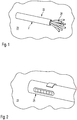
- Figure 1 shows a telecommunication cable 22 having a telecommunication wires 24 and a cable jacket 21.
- Figure 2 shows a tool 25 for removing the cable jacket 21.
- Figure 3 shows the telecommunication cable 22 with the cable jacket 21 being partially removed thereby exposing the telecommunication wires 24.
- the method for installing the telecommunication wall outlet 10 further comprises the step of installing the base plate 12 of the telecommunication wall outlet 10 to the wall 23 and feeding the telecommunication wires 24 through the opening 15 of the base plate 12. See Figure 4 . In this status the telecommunication wires penetrating through the opening 15 of the base plate 12 are at least partially surrounded by the receptacle 16 of the base plate 12.
- the method for installing the telecommunication wall outlet 10 further comprises the step of inserting the wire guide module 11a of the modular jack 11 in the receptacle 16 of the base plate 12 and feeding the telecommunication wires 14 through the opening 17 of the wire guide module 11a. See Figure 5 .
- the telecommunication wires 24 penetrating through the opening 15 of the base plate 12 are at least partially surrounded by the receptacle 16 of the base plate 12 and by the wire guide module 11a of the modular jack 11.
- the method for installing the telecommunication wall outlet 10 further comprises the step of inserting the telecommunication wires 24 into the wire guides 18 of the wire guide module 11a of the modular jack 11. See Figure 6 .
- the telecommunication wires 24 of the cabl3 22 emerging out of the wall 23 are each bent once for inserting the free ends of the same individually in a respective individual wire guide 18 of the wire guide module 11a.
- the method for installing the telecommunication wall outlet 10 further comprises the step of mounting the front panel 13 together the socket module 11b of the modular jack 11 to the base plate 12. See Figure 8 .
- the IDC contacts 14 of the socket module 11b of the modular jack 11 automatically cut into the telecommunication wires 14 positioned within the wire guides 18 of the wire guide module 11a of the modular jack 11.
- the front panel 13 of the telecommunication wall outlet 10 is mounted to the base plate 12 the telecommunication wall outlet 10 by screws 25.
- the method for installing the telecommunication wall outlet 10 may further comprise the step of cutting over-length of the telecommunication wires 24 after the same are inserted into the wire guides 18 of the wire guide module 11a and before mounting the front panel 13 to the base plate 12.
Landscapes
- Engineering & Computer Science (AREA)
- Architecture (AREA)
- Civil Engineering (AREA)
- Structural Engineering (AREA)
- Details Of Connecting Devices For Male And Female Coupling (AREA)
- Connector Housings Or Holding Contact Members (AREA)
Abstract
Description
- The present patent application relates to a telecommunication wall outlet and method for installing the same.
- Telecommunication wall outlets for telecommunication cables are known from practical use. When installing telecommunication wires of a telecommunication cable to such a wall outlet bending of the telecommunication wires is critical with respect to transmission performance. Further on, the available length of the telecommunication wires may be very limited due to the limited space being available within the telecommunication wall outlet. So, there is a need for a telecommunication wall outlet which does not require a large free length of the telecommunication wires and which minimizes bending of the telecommunication wires.
-
EP 1 30 003 B1 US 2011/0249941 A1 show telecommunication outlets according to the prior art. - The present application is based on the object to provide a novel telecommunication wall outlet and method for installing the same.
- The telecommunication wall outlet according to the present patent application is defined in claim 1.
- The telecommunication wall outlet according to the present patent application comprises a modular jack, a base plate and a front panel. The front panel can also be called front cover.
- The modular jack of the telecommunication wall outlet has a wire guide module. The wire guide module is configured to guide telecommunication wires of a telecommunication cable installed in a wall. The modular jack of the telecommunication wall outlet has further a socket module with IDC contacts. The socket module is configured to receive a telecommunication plug and to connect the telecommunication plug to the telecommunication wires of the telecommunication cable installed in the wall.
- The base plate of the telecommunication wall outlet is configured to be installed at the wall. The base plate has an opening for receiving the telecommunication wires being installed in the wall. The base plate of the telecommunication wall outlet has further a receptacle for receiving the wire guide module of the modular jack. The receptacle of the base plate surrounds or encompasses at least partially the opening of the base plate such that telecommunication wires penetrating through the opening are surrounded by the receptacle and by the wire guide module received by the receptacle.
- The front panel of the telecommunication wall outlet is mounted to the base plate. The front panel of the telecommunication wall outlet carries the socket module of the modular jack. The IDC contacts of the socket module of the modular jack electrically contact the telecommunication wires of the telecommunication cable guided by the wire guide module.
- The telecommunication wall outlet does not require a large free length of the telecommunication wires and minimizes bending of the telecommunication wires.
- Preferably, the wire guide module of the modular jack has an opening being axially aligned with the opening of the base plate such that telecommunication wires penetrating through the opening of the base plate also penetrate through the opening of the wire guide module. Such a design of the telecommunication wall outlet further minimizes the required free length of the telecommunication wires and further minimizes bending of the telecommunication wires.
- Preferably, the front panel of the telecommunication wall outlet has an opening for receiving the socket module of the modular jack. The opening of the front panel is axially aligned with the opening of the base plate. Such a design of the telecommunication wall outlet further minimizes the required free length of the telecommunication wires and further minimizes bending of the telecommunication wires.
- Preferably, the base plate of the telecommunication wall outlet is provided as one monolithic element, and/or the wire guide module of the modular jack is provided as one monolithic element, and/or the front panel of the telecommunication wall outlet is provided as one monolithic element. The socket module of the modular jack comprises a housing and the IDC contacts accommodated by the housing. Such a design of the telecommunication wall outlet is simple and reliable.
- The method for installing the telecommunication wall outlet is defined in claim 9. The method comprises at least the following steps: Remove a cable jacket form a telecommunication cable being installed in a wall thereby exposing the telecommunication wires of the telecommunication cable. Install the base plate of the telecommunication wall outlet to the wall and feed the telecommunication wires through the opening of the base plate. Insert the wire guide module of the modular jack in the receptacle of the base plate and feeding the telecommunication wires through the opening of the wire guide module. Insert the telecommunication wires into the wire guides of the wire guide module. Mount the front panel together the socket module of the modular jack to the base plate. The method allows a simple installation not requiring a large free length of the telecommunication wires and minimizing bending of the telecommunication wires.
- Embodiments of the telecommunication wall outlet and of the method for installing the same are given in the dependent claims and the description below. Exemplary embodiments will be explained in more detail with reference to the drawing, in which:
- Figure 1
- shows a telecommunication cable installed in a wall;
- Figure 2
- shows a tool for removing the cable jacket;
- Figure 3
- shows the telecommunication cable with the cable jacked being removed thereby exposing the telecommunication wires of the telecommunication cable;
- Figure 4
- shows a base plate of the telecommunication wall outlet mounted to a wall;
- Figure 5
- shows a wire guide module of a modular jack of the telecommunication wall outlet mounted to the base plate;
- Figure 6
- shows the arrangement of
Figure 5 with free ends of the telecommunication wires being bent and inserted into wire guides of the wire guide module; - Figure 7
- shows a front plate of the telecommunication wall outlet togther with a socket module of the modular jack; and
- Figure 8
- shows the front plate mounted to the base plate.
- The present patent application relates to a telecommunication wall outlet and to a method for installing the telecommunication wall outlet.
- The
telecommunication wall outlet 10 comprises amodular jack 11, abase plate 12 and afront panel 13. Thefront panel 13 can also be called front cover. - The
modular jack 11 of thetelecommunication wall outlet 10 has awire guide module 11a. Thewire guide module 11a is configured to guide telecommunication wires of a telecommunication cable. - The
modular jack 11 of thetelecommunication wall outlet 10 has further asocket module 11b withIDC contacts 14. Thesocket module 11b is configured to receive a telecommunication plug and to connect the telecommunication plug to the telecommunication wires of the telecommunication cable installed in the wall. - The
base plate 12 of thetelecommunication wall outlet 10 is configured to be installed at a wall in which a telecommunication cable is installed. - The
base plate 12 of thetelecommunication wall outlet 10 has anopening 15 for receiving the telecommunication wires of the telecommunication cable being installed in the wall. Thebase plate 12 has further areceptacle 16 for receiving thewire guide module 11a of themodular jack 11. Thereceptacle 16 of thebase plate 12 surrounds or encompasses at least partially theopening 15 of thebase plate 12 such that the telecommunication wires of the telecommunication cable penetrating through theopening 15 are surrounded by thereceptacle 16 and by thewire guide module 11a received by thereceptacle 16. - The
front panel 13 of thetelecommunication wall outlet 10 is mounted to thebase plate 12 of thetelecommunication wall outlet 10. Thefront panel 13 of thetelecommunication wall outlet 10 carries thesocket module 11b of themodular jack 11. TheIDC contacts 14 of thesocket module 11b of the modular jack electrically contact the telecommunication wires of the telecommunication cable guided by thewire guide module 11a. - The
wire guide module 11a of themodular jack 11 has anopening 17 being axially aligned with theopening 15 of thebase plate 12 such that telecommunication wires penetrating through theopening 15 of thebase plate 12 penetrate also through theopening 17 of thewire guide module 11a, namely without bending the telecommunication wires of the telecommunication cable. - The
openings base plate 12 and of thewire guide module 11a of themodular jack 11 are running coaxial when thewire guide module 11a of themodular jack 11 is received by thereceptacle 16 of thebase plate 12 of thetelecommunication wall outlet 10. - The
wire guide module 11a of themodular jack 11 has wire guides 18 for receiving free ends of the telecommunication wires. The telecommunication wires are bent once at their free ends when the free ends are positioned with the wire guides 18wire guide module 11a. Eachwire guide 18 receives one telecommunication wire. - The
front panel 13 of thetelecommunication wall outlet 10 has anopening 19 for receiving thesocket module 11b of themodular jack 11. Theopening 19 of thefront panel 13 is axially aligned with theopening 15 of thebase plate 12 when thefront panel 13 is mounted to thebase plate 12. TheIDC contacts 14 of thesocket module 11b of themodular jack 11 cut directly into the telecommunication wires guided by thewire guide module 11a of themodular jack 11 when thefront panel 13 is mounted to thebase plate 12. - The
base plate 12 of thetelecommunication wall outlet 10 may be provided as one monolithic element. Further on, thewire guide module 11a of themodular jack 11 is provided as one monolithic element. Further on, thefront panel 13 of thetelecommunication wall outlet 10 may be provided as one monolithic element. Thesocket module 11b of themodular jack 11 comprises at least ahousing 20 and theIDC contacts 14 accommodated by thehousing 20. - The present application further provides a method for installing the
telecommunication wall outlet 10. - The method for installing the
telecommunication wall outlet 10 comprises the step partially removing acable jacket 21 form atelecommunication cable 22 being installed in awall 23 thereby exposing thetelecommunication wires 24 of thetelecommunication cable 22.Figure 1 shows atelecommunication cable 22 having atelecommunication wires 24 and acable jacket 21.Figure 2 shows atool 25 for removing thecable jacket 21.Figure 3 shows thetelecommunication cable 22 with thecable jacket 21 being partially removed thereby exposing thetelecommunication wires 24. - The method for installing the
telecommunication wall outlet 10 further comprises the step of installing thebase plate 12 of thetelecommunication wall outlet 10 to thewall 23 and feeding thetelecommunication wires 24 through theopening 15 of thebase plate 12. SeeFigure 4 . In this status the telecommunication wires penetrating through theopening 15 of thebase plate 12 are at least partially surrounded by thereceptacle 16 of thebase plate 12. - The method for installing the
telecommunication wall outlet 10 further comprises the step of inserting thewire guide module 11a of themodular jack 11 in thereceptacle 16 of thebase plate 12 and feeding thetelecommunication wires 14 through theopening 17 of thewire guide module 11a. SeeFigure 5 . In this status thetelecommunication wires 24 penetrating through theopening 15 of thebase plate 12 are at least partially surrounded by thereceptacle 16 of thebase plate 12 and by thewire guide module 11a of themodular jack 11. - It is possible to install first the
base plate 12 of thetelecommunication wall outlet 10 to thewall 23 and then subsequently to install thewire guide module 11a of themodular jack 11 in thereceptacle 16 of thebase plate 12. It is also possible to install first thewire guide module 11a of themodular jack 11 in thereceptacle 16 of thebase plate 12 and then to install the base plate to thewall 23. - The method for installing the
telecommunication wall outlet 10 further comprises the step of inserting thetelecommunication wires 24 into the wire guides 18 of thewire guide module 11a of themodular jack 11. SeeFigure 6 . Thetelecommunication wires 24 of thecabl3 22 emerging out of thewall 23 are each bent once for inserting the free ends of the same individually in a respectiveindividual wire guide 18 of thewire guide module 11a. - The method for installing the
telecommunication wall outlet 10 further comprises the step of mounting thefront panel 13 together thesocket module 11b of themodular jack 11 to thebase plate 12. SeeFigure 8 . When thefront panel 13 becomes mounted to thebase plate 12, theIDC contacts 14 of thesocket module 11b of themodular jack 11 automatically cut into thetelecommunication wires 14 positioned within the wire guides 18 of thewire guide module 11a of themodular jack 11. - The
front panel 13 of thetelecommunication wall outlet 10 is mounted to thebase plate 12 thetelecommunication wall outlet 10 byscrews 25. - The method for installing the
telecommunication wall outlet 10 may further comprise the step of cutting over-length of thetelecommunication wires 24 after the same are inserted into the wire guides 18 of thewire guide module 11a and before mounting thefront panel 13 to thebase plate 12. -
- 10
- telecommunication wall outlet
- 11
- modular jack
- 11a
- wire guide module
- 11b
- socket module
- 12
- base plate
- 13
- front panel
- 14
- IDC contacts
- 15
- opening
- 16
- receptacle
- 17
- opening
- 18
- wire guide
- 19
- opening
- 20
- housing
- 21
- cable jacket
- 22
- telecommunication cable
- 23
- wall
- 24
- telecommunication wires
- 25
- screw
Claims (10)
- A telecommunication wall outlet (10), comprising:a modular jack (11),wherein the modular jack (11) has a wire guide module (11a), the wire guide module (11a) being configured to guide telecommunication wires of a telecommunication cable installed in a wall,wherein the modular jack (11) has a socket module (11b) with IDC contacts (14), the socket module (11b) being configured to receive a telecommunication plug;a base plate (12), the base plate (12) being configured to be installed at the wall,wherein the base plate (12) has an opening (15) for receiving the telecommunication wires of the telecommunication cable,wherein the base plate (12) has a receptacle (16) for receiving the wire guide module (11a) of the modular jack (11),wherein the receptacle (16) of the base plate (11) surrounds or encompasses at least partially the opening (15) of the base plate (12) such that telecommunication wires penetrating through the opening (15) are at least partially surrounded by the receptacle (16) and by the wire guide module (11a) received by the receptacle (16);a front panel (13), the front panel (13) being mounted to the base plate (12),wherein the front panel (13) carries the socket module (11b) of the modular jack (11),wherein the IDC contacts (14) of the socket module (11b) of the modular jack (11) electrically contact the telecommunication wires guided by the wire guide module (11a).
- The telecommunication wall outlet of claim 1, characterized in that
the wire guide module (11a) of the modular jack (11) has an opening (17) being axially aligned with the opening (15) of the base plate (12) such that telecommunication wires penetrating through the opening (15) of the base plate (11a) penetrate also through the opening (17) of the wire guide module (11a). - The telecommunication wall outlet of claim 1 or 2, characterized in that
the wire guide module (11a) of the modular jack (11) has wire guides (18) for receiving bent ends of the telecommunication wires. - The telecommunication wall outlet of claim 3, characterized in that
the front panel (13) has an opening (19) for receiving the socket module (11b) of the modular jack (11). - The telecommunication wall outlet of claim 4, characterized in
the opening (19) of the front panel (13) is axially aligned with the opening (15) of the base plate (12). - The telecommunication wall outlet of claim 5, characterized in that
the IDC contacts (14) of the socket module (11b) of the modular jack (11) cut directly into the telecommunication wires guided by the wire guide module (11a) of the modular jack (11) when the front panel (13) is mounted to the base plate (12). - The telecommunication wall outlet of one of claims 1 to 6, characterized in thatthe base plate (12) is provided as one monolithic element, and/or the wire guide module (11a) of the modular jack (11) is provided as one monolithic element, and/orthe front panel (13) is provided as one monolithic element.
- The telecommunication wall outlet of one of claims 1 to 7, characterized in that
the socket module (11b) of the modular jack (11) comprises at least a housing (20) and the IDC contacts (14) accommodated by the housing (20). - A method for installing the telecommunication wall outlet (10) of one of claims 1 to 8, comprising at least the following steps:removing partially a cable jacket (21) form a telecommunication cable (22) being installed in a wall (23) thereby exposing the telecommunication wires (24) of the telecommunication cable (22),installing the base plate (12) of the telecommunication wall outlet (10) to the wall (23) and feeding the telecommunication wires (24) through the opening (15) of the base plate (12),inserting the wire guide module (11b) of the modular jack (11) in the receptacle (16) of the base plate (12) and feeding the telecommunication wires (24) through the opening (17) of the wire guide module (11b),inserting the telecommunication wires (24) into the wire guides (18) of the wire guide module (11b),mounting the front panel (13) together the socket module (11b) of the modular jack (11) to the base plate (12).
- The method of claim 9, characterized by
cutting over-length of the telecommunication wires (24) after the same are inserted into the wire guides (18) of the wire guide module (11a) and before mounting the front panel (13) to the base plate (12).
Priority Applications (1)
| Application Number | Priority Date | Filing Date | Title |
|---|---|---|---|
| EP19208928.2A EP3823107A1 (en) | 2019-11-13 | 2019-11-13 | Telecommunication wall outlet and method for installing the same |
Applications Claiming Priority (1)
| Application Number | Priority Date | Filing Date | Title |
|---|---|---|---|
| EP19208928.2A EP3823107A1 (en) | 2019-11-13 | 2019-11-13 | Telecommunication wall outlet and method for installing the same |
Publications (1)
| Publication Number | Publication Date |
|---|---|
| EP3823107A1 true EP3823107A1 (en) | 2021-05-19 |
Family
ID=68581452
Family Applications (1)
| Application Number | Title | Priority Date | Filing Date |
|---|---|---|---|
| EP19208928.2A Withdrawn EP3823107A1 (en) | 2019-11-13 | 2019-11-13 | Telecommunication wall outlet and method for installing the same |
Country Status (1)
| Country | Link |
|---|---|
| EP (1) | EP3823107A1 (en) |
Citations (5)
| Publication number | Priority date | Publication date | Assignee | Title |
|---|---|---|---|---|
| EP1300703A2 (en) | 2001-09-28 | 2003-04-09 | The Furukawa Electric Co., Ltd. | Semiconductor laser module and method for simultaneously reducing relative intensity noise and stimulated Brillouin scattering |
| US20110249941A1 (en) | 2008-09-25 | 2011-10-13 | Adc Gmbh | Telecommunication socket outlet |
| US20120052716A1 (en) * | 2010-09-01 | 2012-03-01 | Hon Hai Precision Industry Co., Ltd. | Wall plate assembly |
| US20120196472A1 (en) * | 2011-01-27 | 2012-08-02 | Fitzpatrick Brian J | Modular Communications Jack With User-Selectable Mounting |
| EP2806653A1 (en) * | 2013-05-20 | 2014-11-26 | Konstantinos Ikonomou | Patch panel arrangements, cable terminating devices and methods |
-
2019
- 2019-11-13 EP EP19208928.2A patent/EP3823107A1/en not_active Withdrawn
Patent Citations (5)
| Publication number | Priority date | Publication date | Assignee | Title |
|---|---|---|---|---|
| EP1300703A2 (en) | 2001-09-28 | 2003-04-09 | The Furukawa Electric Co., Ltd. | Semiconductor laser module and method for simultaneously reducing relative intensity noise and stimulated Brillouin scattering |
| US20110249941A1 (en) | 2008-09-25 | 2011-10-13 | Adc Gmbh | Telecommunication socket outlet |
| US20120052716A1 (en) * | 2010-09-01 | 2012-03-01 | Hon Hai Precision Industry Co., Ltd. | Wall plate assembly |
| US20120196472A1 (en) * | 2011-01-27 | 2012-08-02 | Fitzpatrick Brian J | Modular Communications Jack With User-Selectable Mounting |
| EP2806653A1 (en) * | 2013-05-20 | 2014-11-26 | Konstantinos Ikonomou | Patch panel arrangements, cable terminating devices and methods |
Similar Documents
| Publication | Publication Date | Title |
|---|---|---|
| US6350135B1 (en) | Power outlet for divided channel raceway | |
| US6774307B2 (en) | Through-wall electrical system | |
| US4261633A (en) | Wiring module for telephone jack | |
| US5007860A (en) | Modular higher density communications coupling system | |
| US5106325A (en) | Modular higher density communications coupling system | |
| US3989333A (en) | Cable television tap connector box | |
| US5366388A (en) | Wiring distribution system and devices for building wiring | |
| US5658166A (en) | Modular coupler arrangement for use in a building wiring distribution system | |
| WO2020051340A1 (en) | Field terminable single pair ethernet connector | |
| US8650750B2 (en) | Process for assembling a data cable connector module | |
| MXPA02000940A (en) | Shielded telecommunications connector. | |
| CA1209237A (en) | Junction box for poke-thru floor fittings | |
| CN1009235B (en) | Connector bank for cable wires, in particular of telephone cables | |
| US7804026B2 (en) | Enclosure for wiring devices | |
| US5201678A (en) | Set screw bus connector | |
| IL43381A (en) | Multi-conductor cable connector apparatus for telephone and other data transmission systems | |
| US20210021076A1 (en) | Single Pair Ethernet Connector | |
| AU2022209270A1 (en) | Patch panel arrangements cable terminating devices & methods | |
| US5752849A (en) | Tool-less phone jack-to-cable connector | |
| US6007367A (en) | Apparatus for connecting cable cores | |
| US5908326A (en) | Electrical connector | |
| EP0448321A1 (en) | Wiring harness for wall structures | |
| EP4561263A2 (en) | Modular connection system and method | |
| EP0557260A1 (en) | Screwless clamp for connection of conductors | |
| US5382178A (en) | Process and apparatus for the termination of electric cables installed in a building for subsequent connection |
Legal Events
| Date | Code | Title | Description |
|---|---|---|---|
| PUAI | Public reference made under article 153(3) epc to a published international application that has entered the european phase |
Free format text: ORIGINAL CODE: 0009012 |
|
| STAA | Information on the status of an ep patent application or granted ep patent |
Free format text: STATUS: THE APPLICATION HAS BEEN PUBLISHED |
|
| AK | Designated contracting states |
Kind code of ref document: A1 Designated state(s): AL AT BE BG CH CY CZ DE DK EE ES FI FR GB GR HR HU IE IS IT LI LT LU LV MC MK MT NL NO PL PT RO RS SE SI SK SM TR |
|
| STAA | Information on the status of an ep patent application or granted ep patent |
Free format text: STATUS: REQUEST FOR EXAMINATION WAS MADE |
|
| 17P | Request for examination filed |
Effective date: 20211110 |
|
| RBV | Designated contracting states (corrected) |
Designated state(s): AL AT BE BG CH CY CZ DE DK EE ES FI FR GB GR HR HU IE IS IT LI LT LU LV MC MK MT NL NO PL PT RO RS SE SI SK SM TR |
|
| STAA | Information on the status of an ep patent application or granted ep patent |
Free format text: STATUS: THE APPLICATION HAS BEEN WITHDRAWN |
|
| 18W | Application withdrawn |
Effective date: 20220811 |