EP3823087A1 - Over-temperature battery protection - Google Patents
Over-temperature battery protection Download PDFInfo
- Publication number
- EP3823087A1 EP3823087A1 EP20204021.8A EP20204021A EP3823087A1 EP 3823087 A1 EP3823087 A1 EP 3823087A1 EP 20204021 A EP20204021 A EP 20204021A EP 3823087 A1 EP3823087 A1 EP 3823087A1
- Authority
- EP
- European Patent Office
- Prior art keywords
- component
- battery
- temperature
- battery pack
- cells
- Prior art date
- Legal status (The legal status is an assumption and is not a legal conclusion. Google has not performed a legal analysis and makes no representation as to the accuracy of the status listed.)
- Withdrawn
Links
Images






Classifications
-
- H—ELECTRICITY
- H01—ELECTRIC ELEMENTS
- H01M—PROCESSES OR MEANS, e.g. BATTERIES, FOR THE DIRECT CONVERSION OF CHEMICAL ENERGY INTO ELECTRICAL ENERGY
- H01M50/00—Constructional details or processes of manufacture of the non-active parts of electrochemical cells other than fuel cells, e.g. hybrid cells
- H01M50/50—Current conducting connections for cells or batteries
- H01M50/572—Means for preventing undesired use or discharge
- H01M50/574—Devices or arrangements for the interruption of current
- H01M50/583—Devices or arrangements for the interruption of current in response to current, e.g. fuses
-
- H—ELECTRICITY
- H01—ELECTRIC ELEMENTS
- H01M—PROCESSES OR MEANS, e.g. BATTERIES, FOR THE DIRECT CONVERSION OF CHEMICAL ENERGY INTO ELECTRICAL ENERGY
- H01M10/00—Secondary cells; Manufacture thereof
- H01M10/42—Methods or arrangements for servicing or maintenance of secondary cells or secondary half-cells
-
- B—PERFORMING OPERATIONS; TRANSPORTING
- B64—AIRCRAFT; AVIATION; COSMONAUTICS
- B64D—EQUIPMENT FOR FITTING IN OR TO AIRCRAFT; FLIGHT SUITS; PARACHUTES; ARRANGEMENT OR MOUNTING OF POWER PLANTS OR PROPULSION TRANSMISSIONS IN AIRCRAFT
- B64D27/00—Arrangement or mounting of power plants in aircraft; Aircraft characterised by the type or position of power plants
- B64D27/02—Aircraft characterised by the type or position of power plants
- B64D27/24—Aircraft characterised by the type or position of power plants using steam or spring force
-
- B—PERFORMING OPERATIONS; TRANSPORTING
- B64—AIRCRAFT; AVIATION; COSMONAUTICS
- B64D—EQUIPMENT FOR FITTING IN OR TO AIRCRAFT; FLIGHT SUITS; PARACHUTES; ARRANGEMENT OR MOUNTING OF POWER PLANTS OR PROPULSION TRANSMISSIONS IN AIRCRAFT
- B64D27/00—Arrangement or mounting of power plants in aircraft; Aircraft characterised by the type or position of power plants
- B64D27/02—Aircraft characterised by the type or position of power plants
- B64D27/30—Aircraft characterised by electric power plants
- B64D27/33—Hybrid electric aircraft
-
- B—PERFORMING OPERATIONS; TRANSPORTING
- B64—AIRCRAFT; AVIATION; COSMONAUTICS
- B64D—EQUIPMENT FOR FITTING IN OR TO AIRCRAFT; FLIGHT SUITS; PARACHUTES; ARRANGEMENT OR MOUNTING OF POWER PLANTS OR PROPULSION TRANSMISSIONS IN AIRCRAFT
- B64D27/00—Arrangement or mounting of power plants in aircraft; Aircraft characterised by the type or position of power plants
- B64D27/02—Aircraft characterised by the type or position of power plants
- B64D27/30—Aircraft characterised by electric power plants
- B64D27/35—Arrangements for on-board electric energy production, distribution, recovery or storage
- B64D27/357—Arrangements for on-board electric energy production, distribution, recovery or storage using batteries
-
- H—ELECTRICITY
- H01—ELECTRIC ELEMENTS
- H01M—PROCESSES OR MEANS, e.g. BATTERIES, FOR THE DIRECT CONVERSION OF CHEMICAL ENERGY INTO ELECTRICAL ENERGY
- H01M10/00—Secondary cells; Manufacture thereof
- H01M10/42—Methods or arrangements for servicing or maintenance of secondary cells or secondary half-cells
- H01M10/4285—Testing apparatus
-
- H—ELECTRICITY
- H01—ELECTRIC ELEMENTS
- H01M—PROCESSES OR MEANS, e.g. BATTERIES, FOR THE DIRECT CONVERSION OF CHEMICAL ENERGY INTO ELECTRICAL ENERGY
- H01M50/00—Constructional details or processes of manufacture of the non-active parts of electrochemical cells other than fuel cells, e.g. hybrid cells
- H01M50/50—Current conducting connections for cells or batteries
- H01M50/572—Means for preventing undesired use or discharge
- H01M50/574—Devices or arrangements for the interruption of current
- H01M50/581—Devices or arrangements for the interruption of current in response to temperature
-
- H—ELECTRICITY
- H02—GENERATION; CONVERSION OR DISTRIBUTION OF ELECTRIC POWER
- H02J—ELECTRIC POWER NETWORKS; CIRCUIT ARRANGEMENTS OR SYSTEMS FOR SUPPLYING OR DISTRIBUTING ELECTRIC POWER; SYSTEMS FOR STORING ELECTRIC ENERGY
- H02J7/00—Circuit arrangements for charging or discharging batteries or for supplying loads from batteries
- H02J7/60—Circuit arrangements for charging or discharging batteries or for supplying loads from batteries including safety or protection arrangements
- H02J7/65—Circuit arrangements for charging or discharging batteries or for supplying loads from batteries including safety or protection arrangements against overtemperature
-
- H—ELECTRICITY
- H02—GENERATION; CONVERSION OR DISTRIBUTION OF ELECTRIC POWER
- H02J—ELECTRIC POWER NETWORKS; CIRCUIT ARRANGEMENTS OR SYSTEMS FOR SUPPLYING OR DISTRIBUTING ELECTRIC POWER; SYSTEMS FOR STORING ELECTRIC ENERGY
- H02J7/00—Circuit arrangements for charging or discharging batteries or for supplying loads from batteries
- H02J7/60—Circuit arrangements for charging or discharging batteries or for supplying loads from batteries including safety or protection arrangements
- H02J7/663—Circuit arrangements for charging or discharging batteries or for supplying loads from batteries including safety or protection arrangements using battery or load disconnect circuits
-
- H—ELECTRICITY
- H01—ELECTRIC ELEMENTS
- H01M—PROCESSES OR MEANS, e.g. BATTERIES, FOR THE DIRECT CONVERSION OF CHEMICAL ENERGY INTO ELECTRICAL ENERGY
- H01M2200/00—Safety devices for primary or secondary batteries
- H01M2200/10—Temperature sensitive devices
-
- H—ELECTRICITY
- H01—ELECTRIC ELEMENTS
- H01M—PROCESSES OR MEANS, e.g. BATTERIES, FOR THE DIRECT CONVERSION OF CHEMICAL ENERGY INTO ELECTRICAL ENERGY
- H01M2200/00—Safety devices for primary or secondary batteries
- H01M2200/10—Temperature sensitive devices
- H01M2200/103—Fuse
-
- H—ELECTRICITY
- H01—ELECTRIC ELEMENTS
- H01M—PROCESSES OR MEANS, e.g. BATTERIES, FOR THE DIRECT CONVERSION OF CHEMICAL ENERGY INTO ELECTRICAL ENERGY
- H01M2220/00—Batteries for particular applications
- H01M2220/20—Batteries in motive systems, e.g. vehicle, ship, plane
-
- H—ELECTRICITY
- H02—GENERATION; CONVERSION OR DISTRIBUTION OF ELECTRIC POWER
- H02H—EMERGENCY PROTECTIVE CIRCUIT ARRANGEMENTS
- H02H7/00—Emergency protective circuit arrangements specially adapted for specific types of electric machines or apparatus or for sectionalised protection of cable or line systems, and effecting automatic switching in the event of an undesired change from normal working conditions
- H02H7/18—Emergency protective circuit arrangements specially adapted for specific types of electric machines or apparatus or for sectionalised protection of cable or line systems, and effecting automatic switching in the event of an undesired change from normal working conditions for batteries; for accumulators
-
- H—ELECTRICITY
- H02—GENERATION; CONVERSION OR DISTRIBUTION OF ELECTRIC POWER
- H02J—ELECTRIC POWER NETWORKS; CIRCUIT ARRANGEMENTS OR SYSTEMS FOR SUPPLYING OR DISTRIBUTING ELECTRIC POWER; SYSTEMS FOR STORING ELECTRIC ENERGY
- H02J2105/00—Networks for supplying or distributing electric power characterised by their spatial reach or by the load
- H02J2105/30—Networks for supplying or distributing electric power characterised by their spatial reach or by the load the load networks being external to vehicles, i.e. exchanging power with vehicles
- H02J2105/32—Networks for supplying or distributing electric power characterised by their spatial reach or by the load the load networks being external to vehicles, i.e. exchanging power with vehicles for aircrafts
-
- Y—GENERAL TAGGING OF NEW TECHNOLOGICAL DEVELOPMENTS; GENERAL TAGGING OF CROSS-SECTIONAL TECHNOLOGIES SPANNING OVER SEVERAL SECTIONS OF THE IPC; TECHNICAL SUBJECTS COVERED BY FORMER USPC CROSS-REFERENCE ART COLLECTIONS [XRACs] AND DIGESTS
- Y02—TECHNOLOGIES OR APPLICATIONS FOR MITIGATION OR ADAPTATION AGAINST CLIMATE CHANGE
- Y02E—REDUCTION OF GREENHOUSE GAS [GHG] EMISSIONS, RELATED TO ENERGY GENERATION, TRANSMISSION OR DISTRIBUTION
- Y02E60/00—Enabling technologies; Technologies with a potential or indirect contribution to GHG emissions mitigation
- Y02E60/10—Energy storage using batteries
Definitions
- the present disclosure concerns a device for providing over-temperature protection to battery modules, and to battery packs having a number of such battery modules.
- battery packs made up of a number of series-connected battery modules. These battery packs may be used to power one or more motors used to propel the aircraft and/or to provide power to one or more ancillary systems.
- Heating of battery cells beyond their normal operating range can occur for various reasons. For example, a fault may develop in one or more of the modules, or the modules could be exposed to an external source of heat such as a fire, direct sunshine or exhaust gas from a gas turbine engine. Heat from one battery module can spread to others, which could lead to thermal runaway of an entire battery pack. Heating also creates a risk of electric shock, for example by causing damage to electrical insulation and structures that support the cells and bus bars.
- battery packs may be associated with a Battery Management System (BMS) which monitors the temperatures of the battery cells and, for example, controls a breaker to isolate modules that are overheating.
- BMS Battery Management System
- a BMS is typically a complex microprocessor-based system that is vulnerable to failure or loss of power.
- a battery pack protected against thermal runaway comprises a plurality of series-connected battery modules each of which comprises: one or more cells; a circuit breaking component such as a fuse connected in series with the one or more cells; and a temperature activated protection device connected in parallel across the one or more cells and the circuit breaking component.
- the temperature activated protection device comprises a thermally responsive component sensitive to a temperature of the battery module.
- Each protection device is configured, responsive to a temperature sensed by its thermally responsive component exceeding a temperature threshold, to automatically create a short circuit across the one or more cells across which it is connected and to activate the circuit breaking component across which it is connected, thereby isolating its battery module from the other battery modules of the battery pack.
- the thermally responsive component has a first state and a second state.
- the thermally responsive component may be configured, responsive to the temperature exceeding the temperature threshold, to automatically change from the first state to the second state and thereby cause the protection device to create the short circuit and activate the circuit breaking component.
- each protection device further comprises a semiconductor switching device having a normally non-conductive state and a conductive state.
- the temperature sensitive component may be configured, responsive to the temperature exceeding the temperature threshold, to automatically switch the semiconductor switching device from the non-conductive state to the conductive state to create the short circuit across the one or more cells and activate the circuit breaking component.
- the thermally responsive component is connected to a gate terminal of the semiconductor switching device.
- the thermally responsive component may, responsive to the temperature exceeding the temperature threshold, automatically switch the semiconductor switching device from the non-conductive state to the conductive state.
- each protection device further comprises a bypass current path connected in parallel across the one or more cells and the fuse so that current can bypass the cells and fuse of the module if the fuse is blown.
- the bypass current path may include a diode arranged so that the battery pack can discharge through the bypass path but cannot recharge through the bypass path.
- each of the temperature activated protection devices comprises: a first circuit branch comprising a semiconductor switching device having a gate terminal and a normally non-conducting state; and a second circuit branch comprising the thermally responsive component.
- the thermally responsive component may be a thermally actuated switch and may be connected to the gate terminal of the semiconductor switching device.
- the thermally actuated switch may, responsive to the temperature exceeding the temperature threshold, automatically switch from a first state to a second state and thereby switch the semiconductor switching device from its normally non-conducting state to its conducting state in which the semiconductor switching device creates the short circuit and activates the circuit breaking component.
- the second circuit branch further comprises, in series with the thermally actuated switch and the gate terminal of the semiconductor switching device, a resistor and/or a diode.
- the first circuit branch further comprises, connected in parallel across the semiconductor switching device, a component for preventing accidental turn-on of the semiconductor switching device.
- the component may act as a dv/dt filter.
- the component may comprise a resistor in series with a capacitor.
- the first circuit branch further comprises an inductive component for limiting current rise in the semiconductor switching device.
- the second circuit branch further comprises, between the thermally actuated switch and the gate terminal of the semiconductor switching device, a component for conditioning a voltage at the gate terminal for preventing false turn-on of the semiconductor switching device.
- the component may comprise a capacitor and a resistor connected in parallel.
- the second circuit branch further comprises, between the thermally actuated switch and the gate terminal of the semiconductor switching device, a component for providing overvoltage and/or reverse polarity protection to the gate terminal.
- the component may comprise a diode or a Zener diode.
- the first circuit branch further comprises, in series with the semiconductor switching device, a resistor for limiting a current flowing through the semiconductor switching device.
- the first circuit branch comprises a diode in series with the semiconductor switching device.
- the semiconductor switching device comprises a thyristor, a silicon controlled rectifier or a transistor.
- the transistor may be an Insulated Gate Bipolar Transistor (IGBT).
- the thermally responsive component sensitive to the temperature of the battery module is a first thermally responsive component.
- Each of the temperature activated protection devices may further comprise a second thermally responsive component configured sensitive to a temperature of a neighbouring battery module.
- Each protection device may be further configured, responsive to a temperature sensed by its second thermally responsive component exceeding a temperature threshold, to automatically create a short circuit across the one or more cells across which the protection device is connected and to activate the circuit breaking component across which it is connected, thereby isolating its battery module from the other battery modules of the battery pack.
- the neighbouring battery module is an immediately neighbouring battery module.
- the second thermally responsive component is connected in parallel across the first thermally responsive component.
- each of the thermally actuated protection devices is triggerable by a Battery Management System (BMS).
- BMS Battery Management System
- a battery module protected against thermal runaway comprising: one or more cells; a circuit breaking component connected in series with the one or more cells; and a temperature activated protection device connected in parallel across the one or more cells and the circuit breaking component.
- the temperature actuated protection device comprises a thermally responsive component sensitive to a temperature of the battery module.
- the protection device is configured, responsive to a temperature sensed by its thermally responsive component exceeding a temperature threshold, to automatically create a short circuit across the one or more cells and to activate the circuit breaking component.
- a temperature actuated protection device for protecting a battery module against thermal runaway.
- the protection device comprises a thermally responsive component for sensing a temperature of the battery module.
- the protection device is configured, responsive to a temperature sensed by its thermally responsive component exceeding a temperature threshold, to automatically create a short circuit across one or more cells of the battery module across which it is connected and to activate a circuit breaking component across which it is connected.
- an aircraft comprising a battery pack according to the first aspect, a battery module according to the second aspect, or a temperature actuated protection device according to the third aspect.
- a method of protecting a battery pack comprising a plurality of series-connected battery modules against thermal runaway.
- the method comprises: for each of the plurality of battery modules, electrically connecting one or more cells of the battery module to a circuit breaking component in series.
- the method further comprises: for each of the plurality of battery modules, electrically connecting a temperature actuated protection device in parallel with the one or more cells and the circuit breaking component, wherein the protection device comprises a thermally responsive component sensitive to a temperature of the battery module.
- the method further comprises: for at least one of the plurality of battery modules, automatically creating, by the protection device, responsive to a temperature sensed by the thermally responsive component exceeding a predetermined temperature threshold, a short circuit across the one or more cells across which it is connected and activating the circuit breaking component across which it is connected, thereby isolating its battery module from the other battery modules of the battery pack.
- a gas turbine engine is generally indicated at 10, having a principal and rotational axis 11.
- the engine 10 comprises, in axial flow series, an air intake 12, a propulsive fan 13, an intermediate pressure compressor 14, a high-pressure compressor 15, combustion equipment 16, a high-pressure turbine 17, an intermediate pressure turbine 18, a low-pressure turbine 19 and an exhaust nozzle 20.
- a nacelle 21 generally surrounds the engine 10 and defines both the intake 12 and the exhaust nozzle 20.
- the gas turbine engine 10 works in the conventional manner so that air entering the intake 12 is accelerated by the fan 13 to produce two air flows: a first air flow into the intermediate pressure compressor 14 and a second air flow which passes through a bypass duct 22 to provide propulsive thrust.
- the intermediate pressure compressor 14 compresses the air flow directed into it before delivering that air to the high pressure compressor 15 where further compression takes place.
- the compressed air exhausted from the high-pressure compressor 15 is directed into the combustion equipment 16 where it is mixed with fuel and the mixture combusted.
- the resultant hot combustion products then expand through, and thereby drive the high, intermediate and low-pressure turbines 17, 18, 19 before being exhausted through the nozzle 20 to provide additional propulsive thrust.
- the high 17, intermediate 18 and low 19 pressure turbines drive respectively the high pressure compressor 15, intermediate pressure compressor 14 and fan 13, each by suitable interconnecting shaft.
- gas turbine engines to which the present disclosure may be applied may have alternative configurations.
- such engines may have an alternative number of interconnecting shafts (e.g. two) and/or an alternative number of compressors and/or turbines.
- the engine may comprise a gearbox provided in the drive train from a turbine to a compressor and/or fan.
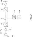
- the propulsion system of a hybrid electric aircraft is generally indicated 200 and incorporates both an engine 210, such as the gas turbine engine 10 described above with reference to Figure 1 , and a battery pack 230. Both the engine 210 and the battery pack 230 are used as energy sources to power a motor-driven propeller 216, as well as ancillary electrical systems (not shown).
- the propulsion system 200 of the hybrid electric aircraft will typically further comprise a generator 211, an AC/DC converter 212, a high voltage DC (HVDC) distribution bus 213, a DC/AC converter 214, a motor 215 that drives the propeller 216, and a DC/DC converter 217.
- a generator 211 an AC/DC converter 212
- HVDC high voltage DC
- DC/AC converter 214 a DC/AC converter 214
- motor 215 that drives the propeller 216
- DC/DC converter 217 DC/DC converter
- a shaft of the engine 210 is coupled to and drives the rotation of a shaft of the generator 211 which thereby produces alternating current.
- the AC/DC converter 212 which faces the generator 211, converts the alternating current into direct current which is fed to various electrical systems via the HVDC distribution bus 213. These electrical systems include the motor 215 that drives the propeller 216.
- the motor 215 will typically be a synchronous motor that interfaces with the HVDC distribution bus 213 via the DC/AC converter 214.
- the battery pack 230 which may be made up of a number of lithium ion battery modules connected in series, is connected to the HVDC distribution bus 213 via the DC/DC converter 217.
- the DC/DC converter 217 converts between a voltage of the battery pack 230 and a voltage of the HVDC distribution bus 213. In this way, the battery pack 230 can replace or supplement the power provided by the engine 210 (by discharging and thereby feeding the HVDC distribution bus 213) or can be charged using the power provided by the engine 210 (by being fed by the HVDC distribution bus 213).
- a battery pack will also appear in the propulsion system of a purely electric aircraft, generally indicated as 300 in Figure 3 .
- the battery pack 330 feeds a HVDC distribution bus 313, possibly via DC/DC converter (not shown), which delivers power to one or more synchronous motors 315 via a DC/AC converter 314.
- the one or more motors 315 drive the one or more propellers 316 that propel that aircraft.
- Battery packs used in these applications may have high terminal voltages, for example 1kV to 3kV.
- the use of high voltages advantageously allows for a reduction in the weight of the power distribution cabling, but it does create risk factors.
- a fault within one or more of the battery modules could lead to cell overheating, which in turn creates a risk of thermal runaway and electric shock.
- Some exemplary reasons for cell heating and thermal runaway include:
- BMS Battery Management System
- a BMS is a complex microprocessor-based system that is vulnerable to failure (including measurement failures) or loss of power, leading to unsafe operation or failure to report errors.
- Systems may also utilize a main fuse and breaker to protect against external short circuits.
- a main fuse or breaker is only able to isolate the battery stack as a whole, and not individual modules.
- the fuse or breaker may take a very long time to blow or trip. Such a delay may mean the effect of the fuse or breaker is too late to avert thermal runaway.
- the present disclosure provides a battery protection device that automatically isolates battery modules that experience or are vulnerable to heating and thermal runaway.
- the protection device is autonomous in that it does not rely on the operation of others system such as a BMS or a separate source of power, so provides a hardware-based layer or protection that can be relied upon if other systems fail. It is also lightweight, which is an important consideration in aerospace applications.
- a battery module protected against thermal runaway is generally indicated at 400.
- the battery module has one or more cells 430 1 , 430 2 ...430 n , which in this arrangement are connected in series but could also be connected in parallel or a mixture of series and parallel.
- the battery module 400 has a positive terminal 401 and a negative terminal 402, allowing the battery module 400 to be connected to other similar battery modules to form a battery pack and/or to be connected to a load.
- the battery module 400 also includes a circuit breaking component 431 which is connected, in series, to the battery cells 430 1-n .
- the circuit breaking component 431 is a fuse, but it could be another component such as a breaker.
- the circuit breaking component 431 is configured to interrupt the flow of current to the battery cells 430 1-n when it subject to an overcurrent condition, for example by blowing (in the case of a fuse) or opening (in the case of a breaker switch) as is well understood by those skilled in the art.
- the rating of the fuse will be selected according to the system requirements, for example taking into account the preferred charge and discharge current of the battery module 400.
- the battery module 400 is protected against thermal runaway by a temperature actuated protection device 432, which is generally indicated in Figure 4 by the box 432 with dashed lines.
- the protection device 432 is connected in parallel across the cells 430 1-n and the fuse 431 at points 403 and 404.
- the protection device 432 and its operation will be described in more detail below but, in brief, if the battery module 400 experiences an over-temperature condition, the protection device 432 automatically creates a short circuit across the cells 430 1-n and the fuse 431 and delivers a current that causes the fuse 431 to blow.
- the thermally actuated protection device 432 includes a thermally responsive component 433 which is sensitive to the temperature of the module 400, and automatically causes the protection device 432 to create the short circuit if the temperature exceeds a temperature threshold.
- the thermally actuated protection device 432 includes the thermally responsive component 433 which is in thermal contact with the module 400.
- the thermally responsive component 433 has at least two states, and transitions from a first state to a second state in the event that its temperature exceeds a threshold.
- the threshold will be chosen according to the system requirements, such as an acceptable range of operating temperatures and on the level of thermal contact between the thermally responsive component 433 and the module.
- the thermally responsive component 433 is a thermal switch, for example a bimetallic switch or a thermistor.
- the thermal switch is normally open, as shown in Figure 4 , and no (or substantially no) current can flow through the protection device 432. However, the thermal switch closes above the threshold temperature, causing the protection device 432 to provide a short circuit across the cells 430 1-n and the fuse 431.
- the protection device 432 typically also includes a semiconductor switching device 434.
- the semiconductor switching device 434 which in Figure 4 is a silicon controlled rectifier (SCR) or thyristor, only conducts current after it has been triggered by injection of a sufficiently high current to its gate terminal 435.
- the thermally responsive component 433 is connected to the gate terminal 435. Below the temperature threshold the gate current is zero so the SCR 434 does not conduct. Above the temperature threshold, however, the thermally responsive component 433 allows sufficient current to pass through the gate 435 so as to trigger the SCR 434 to conduct.
- the SCR has a high current carrying capability, so shorts out the cells 430 1-n across the fuse with a sufficient current to blow the fuse 431.
- the semiconductor switching device 434 will be selected so as to have a gate current trigger threshold appropriate to the system. Likewise, the semiconductor switching device 434 will be selected to provide a sufficiently large l 2 t to blow the fuse 431. While an SCR or thyristor 434 is shown in the arrangement of Figure 4 , other semiconductor switching devices, including a transistor, could be used. For example, as shown in Figure 6 , an Insulated Gate Bipolar Transistor (IGBT) 634 could be used instead of an SCR or thyristor.
- IGBT Insulated Gate Bipolar Transistor
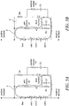
- FIGS 5A-5B The operation of the protection device 432 when the temperature of the battery module 400 sensed by the thermally responsive component 433 has exceeded the temperature threshold is illustrated in Figures 5A-5B .
- normally-open thermal switch 433 has closed because the temperature of the module 433 has exceeded the temperature threshold. Consequently, current can flow along the path generally indicated by line 'X' in Figure 5A .
- the current through path X is not large enough to blow the fuse 431, but the resulting current injected into the gate 435 of the semiconductor switching device 434 is sufficient to trigger the semiconductor switching device 434 to conduct current. Consequently, referring to Figure 5B , current can also flow along the path generally indicated by line 'Y'.
- the current through path Y is large enough to blow the fuse 431, which isolates the cells 430 1-n of the battery module 400 from other battery modules and/or loads that may be connected to the positive and negative terminals 401, 402.
- thermally actuated protection device 432 is shown to include some optional additional components:
- FIG. 6 shows a battery module 600 protected by a thermally actuated protection devices 632 having an alternative arrangement.
- This module 600 and its protection device 632 has many of the same components as, and works in substantially the same way as, the module 400 and protection device 432 of Figure 4 . Only the additional and alternative components not shown in Figure 4 will now be described.
- thermally actuated protection device 432, 632 described above with reference to Figures 4-6 may be used and will occur to those skilled in the art.
- a battery pack comprising a plurality of series-connected battery modules is generally indicated at 700.
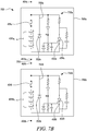
- the battery pack 700 is illustrated as including only two series-connected battery modules 700a, 700b connected at 705, but it will be understood that the battery pack could have any number of modules.
- Each module 700a, 700b has cells 430a 1-n , 430b 1-n in series with a fuse 431a, 431b, and also has a protection device 732a, 732b connected in parallel across the cells and fuse.
- thermally actuated protection devices 732a, 732b of Figures 7A-D are illustrated as having an SCR or thyristor 434 as in Figure 4 , they could equally have an IGBT 634 as in Figure 6 .
- the thermally actuated protection devices 732a, 732b may be the same as or differ from the specific examples described herein.
- the protection devices 732a, 732b each comprise a path 750a, 750b connected in parallel with their semiconductor switching device 434a, 434b and thermal switch 433a, 433b.
- discharge current will flow between the positive and negative terminals 401a, 402a along path W as shown in Figure 7C .
- the module 700a overheats such that the thermal switch 433a closes and the fuse 431a blows, current will flow between the positive and negative terminals 401a, 402a along path Z as shown in Figure 7D .
- the use of a separate path may be desirable to prevent the load current passing through the thermal switch 433 and the current limiting resistor 436, which could cause further heating. It may also be necessary if other paths through the protection device are closed off by diodes, for example.
- bypass paths 750a, 750b are shown to include bypass diodes 752, 752b. This is preferable because it will allow the battery pack 700 to be discharged following the isolation of one or more battery modules, but will block negative current flow through the pack and therefore prevent recharging. In this way, continuity of the power supply during critical situations such as take-off is maintained, but a subsequent recharge is prevented until the battery pack is fixed or replaced.
- the battery pack 700 can also be associated with a BMS (not shown).
- the BMS may be capable of intentionally triggering the protection devices 732a, 732b so that one or more of the modules 700a, 700b can be isolated from the other modules as desired. For example, if the BMS detects an overcharging condition but the main contactor or breaker fails to open, the BMS may force trip a fuse in one or more of the modules by activating the associated semiconductor switching devices.
- a BMS may detect that the temperature of a module 700a, while below the temperature threshold required to trigger its protection device 732a, is increasing. The BMS may therefore intentionally trigger the semiconductor switching device 434a to isolate the module 700a before the temperature rise develops any further. This could be achieved by, for example, providing a BMS-controlled relay in parallel with the thermal switch 433.
- one battery module experiences an over-temperature condition, it may be preferable to isolate not just the over-temperature module but also one or more neighbouring modules as a precaution. For example, even if a given battery module is functioning normally at a normal temperature, it may be vulnerable to heat spread from an overheating battery module. This could, eventually, lead to thermal runaway of a larger part or even the entire battery pack. Isolating the neighbouring modules can therefore help contain a local problem and prevent it developing into a wider problem. As another example, if an over-temperature module enters into thermal runaway resulting in insulation damage and a short circuit to ground, it may be desirable to isolate the neighbouring module so that is not capable of contributing current to this fault.
- FIG 8 illustrates a battery pack 800 made up of battery modules 800a, 800b, 800c that incorporate thermally actuated protection devices 832a, 832b, 832c to protect against such an occurrence. It is noted that only a portion of the protection device 832a of module 800a is visible in Figure 8 , and that module 800c is not visible at all except a portion of its protection device 832c. The arrangement will be described with reference to module 800b and its protection device 832b which are clearly visible in Figure 8 .
- the protection device 832b is generally indicated by dashed lines, which can be seen to partially extend outside of the battery module 800b into neighbouring module 800a.
- the protection device 832b of battery module 800b includes a second thermally responsive component 842b.
- the second thermally responsive component 842b is in thermal contact with one of the battery modules that neighbours module 800b. In this case it is in thermal contact with the immediately neighbouring and above module 800a. Since the second thermally responsive component 842b is in thermal contact with neighbouring module 800a, it is sensitive to the temperature of the neighbouring module 800a.
- the second thermally responsive component 842b which in this case is a normally-open thermal switch like the thermal switch 833 described above, is connected in parallel across the first thermally responsive component 833b.
- the thermal switch 842b closes. This provides a current path around the first thermal switch 833b so that current is provided at the gate 835b of the semiconductor switching device 834b even if the battery module 800b is itself below the temperature threshold associated with the first thermal switch 833b.
- the current at the gate 835b triggers the semiconductor switching device 834b to conduct current, which short circuits the cells 830b 1-n across the fuse 830b and blows the fuse, thus isolating the cells 830b 1-n of battery 800b.
- an over-temperature condition in a neighbouring battery module 800a triggers the thermally actuated protection device 832b of battery module 800b.
- the second thermally responsive component 842b of the protection device 832b is thermally coupled to the immediately neighbouring and above module 800a, it could equally have been thermally coupled with immediately neighbouring and below module 800c.
- the second thermally responsive component 842b could also be thermally coupled to a next nearest neighbour, or even a battery module further away than the next nearest neighbour if, for example, there is a particularly strong thermal path between two relatively electrically distant modules.
- the protection device 832b of the battery module 800b could include more than two thermally responsive components 433b, 842b.
- the protection device 832b could include a third thermally responsive component in parallel with the first and second thermally responsive components 833b, 842b and thermally coupled to a different neighbouring module, for example module 800c.
- the protection device 832b could be configured to create a short circuit across the cells 430b 1-n and fuse 431b of its module 800b if its temperature or the temperature of any of its neighbouring modules 800a, 800c experience an over-temperate condition.
- the temperature threshold associated with the second thermally responsive component 842b may be the same or different from the temperature threshold associated with the first thermally responsive component 433b.
- the temperature threshold associated with the second thermally responsive component 842b is higher than the temperature threshold associated with the first thermally responsive component 433b because an over-temperature condition in a neighbouring module 800a may only be a concern if the neighbouring module 800a is particularly high.
- thermally actuated protection devices 832a-c of Figure 8 are illustrated as the same as, other than the second thermally responsive component 842a-c, 432 of Figure 4 , they could equally correspond to the protection device 632 of Figure 6 . They could also differ from the specific examples described herein.
Landscapes
- Engineering & Computer Science (AREA)
- Aviation & Aerospace Engineering (AREA)
- Chemical & Material Sciences (AREA)
- Chemical Kinetics & Catalysis (AREA)
- Electrochemistry (AREA)
- General Chemical & Material Sciences (AREA)
- Power Engineering (AREA)
- Manufacturing & Machinery (AREA)
- Protection Of Static Devices (AREA)
Abstract
Description
- The present disclosure concerns a device for providing over-temperature protection to battery modules, and to battery packs having a number of such battery modules.
- Future aerospace applications such as electric and hybrid electric aircraft will likely use high voltage battery packs made up of a number of series-connected battery modules. These battery packs may be used to power one or more motors used to propel the aircraft and/or to provide power to one or more ancillary systems.
- Heating of battery cells beyond their normal operating range can occur for various reasons. For example, a fault may develop in one or more of the modules, or the modules could be exposed to an external source of heat such as a fire, direct sunshine or exhaust gas from a gas turbine engine. Heat from one battery module can spread to others, which could lead to thermal runaway of an entire battery pack. Heating also creates a risk of electric shock, for example by causing damage to electrical insulation and structures that support the cells and bus bars.
- Clearly it is desirable to protect against the consequences of excessive cell heating. To this end, battery packs may be associated with a Battery Management System (BMS) which monitors the temperatures of the battery cells and, for example, controls a breaker to isolate modules that are overheating. However, a BMS is typically a complex microprocessor-based system that is vulnerable to failure or loss of power.
- It would be desirable for batteries to have a hardware-based second layer of protection, especially for aerospace applications where functional design assurance is necessary.
- Furthermore, it would be desirable for such a hardware-based layer of protection to isolate overheating battery modules, or battery modules which are vulnerable to thermal runaway.
- According to a first aspect there is provided a battery pack protected against thermal runaway. The battery pack comprises a plurality of series-connected battery modules each of which comprises: one or more cells; a circuit breaking component such as a fuse connected in series with the one or more cells; and a temperature activated protection device connected in parallel across the one or more cells and the circuit breaking component. The temperature activated protection device comprises a thermally responsive component sensitive to a temperature of the battery module. Each protection device is configured, responsive to a temperature sensed by its thermally responsive component exceeding a temperature threshold, to automatically create a short circuit across the one or more cells across which it is connected and to activate the circuit breaking component across which it is connected, thereby isolating its battery module from the other battery modules of the battery pack.
- In an arrangement, the thermally responsive component has a first state and a second state. The thermally responsive component may be configured, responsive to the temperature exceeding the temperature threshold, to automatically change from the first state to the second state and thereby cause the protection device to create the short circuit and activate the circuit breaking component.
- In an arrangement, each protection device further comprises a semiconductor switching device having a normally non-conductive state and a conductive state. The temperature sensitive component may be configured, responsive to the temperature exceeding the temperature threshold, to automatically switch the semiconductor switching device from the non-conductive state to the conductive state to create the short circuit across the one or more cells and activate the circuit breaking component.
- In an arrangement, the thermally responsive component is connected to a gate terminal of the semiconductor switching device. The thermally responsive component may, responsive to the temperature exceeding the temperature threshold, automatically switch the semiconductor switching device from the non-conductive state to the conductive state.
- In an arrangement, each protection device further comprises a bypass current path connected in parallel across the one or more cells and the fuse so that current can bypass the cells and fuse of the module if the fuse is blown. The bypass current path may include a diode arranged so that the battery pack can discharge through the bypass path but cannot recharge through the bypass path.
- In an arrangement, each of the temperature activated protection devices comprises: a first circuit branch comprising a semiconductor switching device having a gate terminal and a normally non-conducting state; and a second circuit branch comprising the thermally responsive component. The thermally responsive component may be a thermally actuated switch and may be connected to the gate terminal of the semiconductor switching device. The thermally actuated switch may, responsive to the temperature exceeding the temperature threshold, automatically switch from a first state to a second state and thereby switch the semiconductor switching device from its normally non-conducting state to its conducting state in which the semiconductor switching device creates the short circuit and activates the circuit breaking component.
- In an arrangement, the second circuit branch further comprises, in series with the thermally actuated switch and the gate terminal of the semiconductor switching device, a resistor and/or a diode.
- In an arrangement, the first circuit branch further comprises, connected in parallel across the semiconductor switching device, a component for preventing accidental turn-on of the semiconductor switching device. The component may act as a dv/dt filter. The component may comprise a resistor in series with a capacitor.
- In an arrangement, the first circuit branch further comprises an inductive component for limiting current rise in the semiconductor switching device.
- In an arrangement, the second circuit branch further comprises, between the thermally actuated switch and the gate terminal of the semiconductor switching device, a component for conditioning a voltage at the gate terminal for preventing false turn-on of the semiconductor switching device. The component may comprise a capacitor and a resistor connected in parallel.
- In an arrangement, the second circuit branch further comprises, between the thermally actuated switch and the gate terminal of the semiconductor switching device, a component for providing overvoltage and/or reverse polarity protection to the gate terminal. The component may comprise a diode or a Zener diode.
- In an arrangement, the first circuit branch further comprises, in series with the semiconductor switching device, a resistor for limiting a current flowing through the semiconductor switching device.
- In an arrangement, the first circuit branch comprises a diode in series with the semiconductor switching device.
- In an arrangement, the semiconductor switching device comprises a thyristor, a silicon controlled rectifier or a transistor. The transistor may be an Insulated Gate Bipolar Transistor (IGBT).
- In an arrangement, the thermally responsive component sensitive to the temperature of the battery module is a first thermally responsive component. Each of the temperature activated protection devices may further comprise a second thermally responsive component configured sensitive to a temperature of a neighbouring battery module. Each protection device may be further configured, responsive to a temperature sensed by its second thermally responsive component exceeding a temperature threshold, to automatically create a short circuit across the one or more cells across which the protection device is connected and to activate the circuit breaking component across which it is connected, thereby isolating its battery module from the other battery modules of the battery pack.
- In an arrangement, the neighbouring battery module is an immediately neighbouring battery module.
- In an arrangement, the second thermally responsive component is connected in parallel across the first thermally responsive component.
- In an arrangement, each of the thermally actuated protection devices is triggerable by a Battery Management System (BMS).
- According to a second aspect, there is provided a battery module protected against thermal runaway. The battery module comprises: one or more cells; a circuit breaking component connected in series with the one or more cells; and a temperature activated protection device connected in parallel across the one or more cells and the circuit breaking component. The temperature actuated protection device comprises a thermally responsive component sensitive to a temperature of the battery module. The protection device is configured, responsive to a temperature sensed by its thermally responsive component exceeding a temperature threshold, to automatically create a short circuit across the one or more cells and to activate the circuit breaking component.
- According to a third aspect, there is provided a temperature actuated protection device for protecting a battery module against thermal runaway. The protection device comprises a thermally responsive component for sensing a temperature of the battery module. The protection device is configured, responsive to a temperature sensed by its thermally responsive component exceeding a temperature threshold, to automatically create a short circuit across one or more cells of the battery module across which it is connected and to activate a circuit breaking component across which it is connected.
- According to a fourth aspect, there is provided an aircraft comprising a battery pack according to the first aspect, a battery module according to the second aspect, or a temperature actuated protection device according to the third aspect.
- According to a fifth aspect, there is provided a method of protecting a battery pack comprising a plurality of series-connected battery modules against thermal runaway. The method comprises: for each of the plurality of battery modules, electrically connecting one or more cells of the battery module to a circuit breaking component in series. The method further comprises: for each of the plurality of battery modules, electrically connecting a temperature actuated protection device in parallel with the one or more cells and the circuit breaking component, wherein the protection device comprises a thermally responsive component sensitive to a temperature of the battery module. The method further comprises: for at least one of the plurality of battery modules, automatically creating, by the protection device, responsive to a temperature sensed by the thermally responsive component exceeding a predetermined temperature threshold, a short circuit across the one or more cells across which it is connected and activating the circuit breaking component across which it is connected, thereby isolating its battery module from the other battery modules of the battery pack.
- The skilled person will appreciate that except where mutually exclusive, a feature described in relation to any one of the above aspects may be applied mutatis mutandis to any other aspect. Specifically, the optional features described above for the first aspect could equally be applied to each of the second, third, fourth and fifth aspect but are not repeated for brevity. Furthermore except where mutually exclusive any feature described herein may be applied to any aspect and/or combined with any other feature described herein.
- Embodiments will now be described by way of example only, with reference to the Figures, in which:
-
Figure 1 is a sectional side view of a gas turbine engine; -
Figure 2 is a schematic illustration of a hybrid electric aircraft propulsion system; -
Figure 3 is a schematic illustration of a purely electric aircraft propulsion system; -
Figure 4 is a circuit diagram of a battery module incorporating a temperature actuated protection device according to the present disclosure; -
Figures 5A and 5B are circuit diagrams illustrating the operation of the protection device ofFigure 4 ; -
Figure 6 is a circuit diagram illustrating another arrangement of the thermally actuated protection device according to the present disclosure; -
Figure 7A is a circuit diagram illustrating a battery pack comprising a plurality of series-connected battery modules according to the present disclosure; -
Figure 7B is a circuit diagram illustrating a battery pack comprising a plurality of series-connected battery modules according to the present disclosure, including a bypass circuit path; -
Figures 7C and 7D are circuit diagrams illustrating the operation of the bypass circuit path; and -
Figure 8 is a circuit diagram illustrating an arrangement for isolating a battery module and its neighbouring battery modules in the event of thermal runaway according to the present disclosure. - With reference to
Figure 1 , a gas turbine engine is generally indicated at 10, having a principal androtational axis 11. Theengine 10 comprises, in axial flow series, anair intake 12, apropulsive fan 13, anintermediate pressure compressor 14, a high-pressure compressor 15,combustion equipment 16, a high-pressure turbine 17, anintermediate pressure turbine 18, a low-pressure turbine 19 and anexhaust nozzle 20. Anacelle 21 generally surrounds theengine 10 and defines both theintake 12 and theexhaust nozzle 20. - The
gas turbine engine 10 works in the conventional manner so that air entering theintake 12 is accelerated by thefan 13 to produce two air flows: a first air flow into theintermediate pressure compressor 14 and a second air flow which passes through abypass duct 22 to provide propulsive thrust. Theintermediate pressure compressor 14 compresses the air flow directed into it before delivering that air to thehigh pressure compressor 15 where further compression takes place. - The compressed air exhausted from the high-
pressure compressor 15 is directed into thecombustion equipment 16 where it is mixed with fuel and the mixture combusted. The resultant hot combustion products then expand through, and thereby drive the high, intermediate and low-pressure turbines nozzle 20 to provide additional propulsive thrust. The high 17, intermediate 18 and low 19 pressure turbines drive respectively thehigh pressure compressor 15,intermediate pressure compressor 14 andfan 13, each by suitable interconnecting shaft. - Other gas turbine engines to which the present disclosure may be applied may have alternative configurations. By way of example such engines may have an alternative number of interconnecting shafts (e.g. two) and/or an alternative number of compressors and/or turbines. Further the engine may comprise a gearbox provided in the drive train from a turbine to a compressor and/or fan. Now referring to
Figure 2 , the propulsion system of a hybrid electric aircraft is generally indicated 200 and incorporates both anengine 210, such as thegas turbine engine 10 described above with reference toFigure 1 , and abattery pack 230. Both theengine 210 and thebattery pack 230 are used as energy sources to power a motor-drivenpropeller 216, as well as ancillary electrical systems (not shown). - The
propulsion system 200 of the hybrid electric aircraft will typically further comprise agenerator 211, an AC/DC converter 212, a high voltage DC (HVDC)distribution bus 213, a DC/AC converter 214, amotor 215 that drives thepropeller 216, and a DC/DC converter 217. - A shaft of the
engine 210 is coupled to and drives the rotation of a shaft of thegenerator 211 which thereby produces alternating current. The AC/DC converter 212, which faces thegenerator 211, converts the alternating current into direct current which is fed to various electrical systems via theHVDC distribution bus 213. These electrical systems include themotor 215 that drives thepropeller 216. Themotor 215 will typically be a synchronous motor that interfaces with theHVDC distribution bus 213 via the DC/AC converter 214. - The
battery pack 230, which may be made up of a number of lithium ion battery modules connected in series, is connected to theHVDC distribution bus 213 via the DC/DC converter 217. The DC/DC converter 217 converts between a voltage of thebattery pack 230 and a voltage of theHVDC distribution bus 213. In this way, thebattery pack 230 can replace or supplement the power provided by the engine 210 (by discharging and thereby feeding the HVDC distribution bus 213) or can be charged using the power provided by the engine 210 (by being fed by the HVDC distribution bus 213). - A battery pack will also appear in the propulsion system of a purely electric aircraft, generally indicated as 300 in
Figure 3 . Thebattery pack 330 feeds aHVDC distribution bus 313, possibly via DC/DC converter (not shown), which delivers power to one or moresynchronous motors 315 via a DC/AC converter 314. The one ormore motors 315 drive the one ormore propellers 316 that propel that aircraft. - Battery packs used in these applications may have high terminal voltages, for example 1kV to 3kV. The use of high voltages advantageously allows for a reduction in the weight of the power distribution cabling, but it does create risk factors. For example, a fault within one or more of the battery modules could lead to cell overheating, which in turn creates a risk of thermal runaway and electric shock. Some exemplary reasons for cell heating and thermal runaway include:
- Exposure to an external source of heat such as fire, direct sunshine or exhaust gas from a gas turbine.
- Loss of normal cooling to a battery module, for example a loss of cooling air flow due to a vent blockage; a loss of cooling liquid flow due to a pipe blockage; or a loss of thermal contact between a cell and its heatsink.
- Over-charging of cells, even at low current levels, or the use of an excessively high charging current, which could generate heat at a greater rate than the system is able to cool the cells.
- Abnormally high discharge current, which could generate heat at a greater rate than the system is able to cool the cells.
- Internal short circuit. An internal short circuit can be caused by dendrite formation, which can happen if the module is subject to over-discharging or charging at cold temperatures.
- External short circuit.
- Mechanical damage to a cell, which could cause internal short circuit.
- Poor electrical contact leading to localized heating. For example, loosening of the tab screws, insufficient torque on connectors, a faulty separator, poorly welded tabs and tab corrosion can all cause poor electrical contact to one or more cells of a battery module.
- Manufacturing or material defects.
- It is clearly desirable to reduce the risks associated with cell heating. Detecting and isolating faulty battery modules early enough may avert thermal runaway. Even if thermal runaway cannot be averted, isolating faulty modules reduces the risk of electric shock, which is important for passengers, crew and first responders following an incident.
- Systems may utilize a Battery Management System (BMS) that monitors the temperatures of the battery cells and, for example, controls a breaker to isolate modules that are overheating. However, a BMS is a complex microprocessor-based system that is vulnerable to failure (including measurement failures) or loss of power, leading to unsafe operation or failure to report errors.
- Systems may also utilize a main fuse and breaker to protect against external short circuits. However, a main fuse or breaker is only able to isolate the battery stack as a whole, and not individual modules. Furthermore, if the short circuit current is low, as in the case of a high impedance fault, the fuse or breaker may take a very long time to blow or trip. Such a delay may mean the effect of the fuse or breaker is too late to avert thermal runaway.
- To address these and/or other problems, the present disclosure provides a battery protection device that automatically isolates battery modules that experience or are vulnerable to heating and thermal runaway. The protection device is autonomous in that it does not rely on the operation of others system such as a BMS or a separate source of power, so provides a hardware-based layer or protection that can be relied upon if other systems fail. It is also lightweight, which is an important consideration in aerospace applications.
- With reference to
Figure 4 , a battery module protected against thermal runaway is generally indicated at 400. The battery module has one or more cells 4301, 4302...430n, which in this arrangement are connected in series but could also be connected in parallel or a mixture of series and parallel. Thebattery module 400 has apositive terminal 401 and anegative terminal 402, allowing thebattery module 400 to be connected to other similar battery modules to form a battery pack and/or to be connected to a load. - The
battery module 400 also includes acircuit breaking component 431 which is connected, in series, to the battery cells 4301-n. InFigure 4 thecircuit breaking component 431 is a fuse, but it could be another component such as a breaker. Thecircuit breaking component 431 is configured to interrupt the flow of current to the battery cells 4301-n when it subject to an overcurrent condition, for example by blowing (in the case of a fuse) or opening (in the case of a breaker switch) as is well understood by those skilled in the art. The rating of the fuse will be selected according to the system requirements, for example taking into account the preferred charge and discharge current of thebattery module 400. - The
battery module 400 is protected against thermal runaway by a temperature actuatedprotection device 432, which is generally indicated inFigure 4 by thebox 432 with dashed lines. Theprotection device 432 is connected in parallel across the cells 4301-n and thefuse 431 atpoints protection device 432 and its operation will be described in more detail below but, in brief, if thebattery module 400 experiences an over-temperature condition, theprotection device 432 automatically creates a short circuit across the cells 4301-n and thefuse 431 and delivers a current that causes thefuse 431 to blow. To this end, the thermally actuatedprotection device 432 includes a thermallyresponsive component 433 which is sensitive to the temperature of themodule 400, and automatically causes theprotection device 432 to create the short circuit if the temperature exceeds a temperature threshold. - In more detail, the thermally actuated
protection device 432 includes the thermallyresponsive component 433 which is in thermal contact with themodule 400. The thermallyresponsive component 433 has at least two states, and transitions from a first state to a second state in the event that its temperature exceeds a threshold. The threshold will be chosen according to the system requirements, such as an acceptable range of operating temperatures and on the level of thermal contact between the thermallyresponsive component 433 and the module. - In the arrangement of
Figure 4 the thermallyresponsive component 433 is a thermal switch, for example a bimetallic switch or a thermistor. The thermal switch is normally open, as shown inFigure 4 , and no (or substantially no) current can flow through theprotection device 432. However, the thermal switch closes above the threshold temperature, causing theprotection device 432 to provide a short circuit across the cells 4301-n and thefuse 431. - In order to provide a current that is sufficiently large to blow the
fuse 431, theprotection device 432 typically also includes asemiconductor switching device 434. Thesemiconductor switching device 434, which inFigure 4 is a silicon controlled rectifier (SCR) or thyristor, only conducts current after it has been triggered by injection of a sufficiently high current to itsgate terminal 435. To this end, the thermallyresponsive component 433 is connected to thegate terminal 435. Below the temperature threshold the gate current is zero so theSCR 434 does not conduct. Above the temperature threshold, however, the thermallyresponsive component 433 allows sufficient current to pass through thegate 435 so as to trigger theSCR 434 to conduct. The SCR has a high current carrying capability, so shorts out the cells 4301-n across the fuse with a sufficient current to blow thefuse 431. - The
semiconductor switching device 434 will be selected so as to have a gate current trigger threshold appropriate to the system. Likewise, thesemiconductor switching device 434 will be selected to provide a sufficiently large l2t to blow thefuse 431. While an SCR orthyristor 434 is shown in the arrangement ofFigure 4 , other semiconductor switching devices, including a transistor, could be used. For example, as shown inFigure 6 , an Insulated Gate Bipolar Transistor (IGBT) 634 could be used instead of an SCR or thyristor. - The operation of the
protection device 432 when the temperature of thebattery module 400 sensed by the thermallyresponsive component 433 has exceeded the temperature threshold is illustrated inFigures 5A-5B . Referring first toFigure 5A , normally-openthermal switch 433 has closed because the temperature of themodule 433 has exceeded the temperature threshold. Consequently, current can flow along the path generally indicated by line 'X' inFigure 5A . The current through path X is not large enough to blow thefuse 431, but the resulting current injected into thegate 435 of thesemiconductor switching device 434 is sufficient to trigger thesemiconductor switching device 434 to conduct current. Consequently, referring toFigure 5B , current can also flow along the path generally indicated by line 'Y'. Due to the high current carrying capability of thesemiconductor switching device 434, the current through path Y is large enough to blow thefuse 431, which isolates the cells 4301-n of thebattery module 400 from other battery modules and/or loads that may be connected to the positive andnegative terminals - Returning to
Figure 4 , the thermally actuatedprotection device 432 is shown to include some optional additional components: - A
resistor 436 may be provided in series with the thermallyresponsive component 433 and its connection to thegate 435 of thesemiconductor switching device 434 to adjust the level of current used to trigger thesemiconductor switching device 434. - Components may be provided to reduce the likelihood of an accidental turn-on of the
semiconductor switching device 434 in the event of voltage transients. A dv/dt filter, which inFigure 4 takes the form of a snubber (a series-connectedresistor 437 andcapacitor 438 connected in parallel across the SCR 434), may be provided. - The thermally actuated
protection device 432 may include components to prevent accidental turn-on of thesemiconductor switching device 434. InFigure 4 acapacitor 439 and aresistor 440 connected in parallel between the input to thegate terminal 435 and thenegative terminal 402 for this purpose. - The thermally actuated
protection device 432 may include a current limitingresistor 441 to limit the short circuit current level. An inductor (not shown) may be connected in series with theresistor 441 to provide di/dt protection of the SCR, limiting the rate of rise of current in the device during turn on. - The thermally actuated
protection device 432 may include a diode (not shown inFigure 4 but shown inFigures 7B-7D ) to protect the gate against reverse polarity across the gate-cathode junction of the SCR. - Components may be provided to reduce the likelihood of an accidental turn-on of the
semiconductor switching device 434 in the event of current transients. - If the
semiconductor switching device 434 does not possess substantial reverse blocking capability then this capability may be introduced by adding a diode in series with the switching device. InFigure 4 theSCR 434 possesses reverse blocking capability and therefore a reverse blocking diode is not required, and so none is shown. Reverse blocking may be required to prevent the reverse flow of current from thenegative terminal 402 to thepositive terminal 401 bypassing the blownfuse 431. - Similar reverse blocking functionality may be provided by a diode (not shown) in series with the thermally
responsive component 433 and, if the present, theresistor 436. -
Figure 6 shows abattery module 600 protected by a thermally actuatedprotection devices 632 having an alternative arrangement. Thismodule 600 and itsprotection device 632 has many of the same components as, and works in substantially the same way as, themodule 400 andprotection device 432 ofFigure 4 . Only the additional and alternative components not shown inFigure 4 will now be described. - As mentioned above and as shown in
Figure 6 , the semiconductor switching device may be anIGBT 634 instead of an SCR orthyristor 434. In this case, althoughFigure 6 shows aresistor 437 and acapacitor 438 for accidental turn-on protection, different turn-on protection may be used. -
Protection device 632 includes a component for providing overvoltage and reverse polarity protection between the gate and emitter, in this case aZener diode 642 connected between the input to thegate terminal 435 and thenegative terminal 402. - Alternative and additional components for implementing the thermally actuated
protection device Figures 4-6 may be used and will occur to those skilled in the art. - Referring to
Figures 7A-D , a battery pack comprising a plurality of series-connected battery modules is generally indicated at 700. For simplicity thebattery pack 700 is illustrated as including only two series-connectedbattery modules 700a, 700b connected at 705, but it will be understood that the battery pack could have any number of modules. Eachmodule 700a, 700b hascells 430a1-n, 430b1-n in series with afuse 431a, 431b, and also has aprotection device 732a, 732b connected in parallel across the cells and fuse. - While the thermally actuated
protection devices 732a, 732b ofFigures 7A-D are illustrated as having an SCR orthyristor 434 as inFigure 4 , they could equally have anIGBT 634 as inFigure 6 . The thermally actuatedprotection devices 732a, 732b may be the same as or differ from the specific examples described herein. - It should be appreciated from
Figures 7A-D that in the event that thecells 430a1-n of onebattery module 700a are isolated due an over-temperature condition inmodule 700a, there may still be a current path between thepositive terminal 401a and the negative terminal 402a of thebattery module 700a. This means that the loss of one ormore battery modules 700a of thebattery pack 700 may not result in the complete loss of function of theentire battery pack 700, as the remaining, working, battery modules 700b may not be totally isolated from each other. This may be of critical importance in situations where the continuity of the power supply is required for safety. For example, sudden loss of power during take-off could have dire consequences and so it is important that when one module is isolated, the remaining modules remain connected. While the loss of a series connected module will result in a reduction in the terminal voltage of the battery pack, the DC/DC converter 217 can accommodate this. - First referring to
Figure 7A , current may still be able to flow between thepositive terminal 401a and thenegative terminal 402a via an available path in theprotection device 732a. - Now referring to
Figures 7B-D , it may be preferable to provide an additional separate current path for module bypass. Specifically, inFigure 7B theprotection devices 732a, 732b each comprise apath 750a, 750b connected in parallel with theirsemiconductor switching device thermal switch 433a, 433b. In normal operation discharge current will flow between the positive andnegative terminals Figure 7C . However, if themodule 700a overheats such that thethermal switch 433a closes and thefuse 431a blows, current will flow between the positive andnegative terminals Figure 7D . The use of a separate path may be desirable to prevent the load current passing through thethermal switch 433 and the current limitingresistor 436, which could cause further heating. It may also be necessary if other paths through the protection device are closed off by diodes, for example. - The
bypass paths 750a, 750b are shown to includebypass diodes 752, 752b. This is preferable because it will allow thebattery pack 700 to be discharged following the isolation of one or more battery modules, but will block negative current flow through the pack and therefore prevent recharging. In this way, continuity of the power supply during critical situations such as take-off is maintained, but a subsequent recharge is prevented until the battery pack is fixed or replaced. - The
battery pack 700 can also be associated with a BMS (not shown). In this case the BMS may be capable of intentionally triggering theprotection devices 732a, 732b so that one or more of themodules 700a, 700b can be isolated from the other modules as desired. For example, if the BMS detects an overcharging condition but the main contactor or breaker fails to open, the BMS may force trip a fuse in one or more of the modules by activating the associated semiconductor switching devices. As another example, a BMS may detect that the temperature of amodule 700a, while below the temperature threshold required to trigger itsprotection device 732a, is increasing. The BMS may therefore intentionally trigger thesemiconductor switching device 434a to isolate themodule 700a before the temperature rise develops any further. This could be achieved by, for example, providing a BMS-controlled relay in parallel with thethermal switch 433. - In the event that one battery module experiences an over-temperature condition, it may be preferable to isolate not just the over-temperature module but also one or more neighbouring modules as a precaution. For example, even if a given battery module is functioning normally at a normal temperature, it may be vulnerable to heat spread from an overheating battery module. This could, eventually, lead to thermal runaway of a larger part or even the entire battery pack. Isolating the neighbouring modules can therefore help contain a local problem and prevent it developing into a wider problem. As another example, if an over-temperature module enters into thermal runaway resulting in insulation damage and a short circuit to ground, it may be desirable to isolate the neighbouring module so that is not capable of contributing current to this fault.
-
Figure 8 illustrates abattery pack 800 made up ofbattery modules protection devices protection device 832a ofmodule 800a is visible inFigure 8 , and thatmodule 800c is not visible at all except a portion of itsprotection device 832c. The arrangement will be described with reference tomodule 800b and its protection device 832b which are clearly visible inFigure 8 . The protection device 832b is generally indicated by dashed lines, which can be seen to partially extend outside of thebattery module 800b into neighbouringmodule 800a. - As can be seen, the protection device 832b of
battery module 800b includes a second thermally responsive component 842b. The second thermally responsive component 842b is in thermal contact with one of the battery modules thatneighbours module 800b. In this case it is in thermal contact with the immediately neighbouring and abovemodule 800a. Since the second thermally responsive component 842b is in thermal contact withneighbouring module 800a, it is sensitive to the temperature of the neighbouringmodule 800a. - The second thermally responsive component 842b, which in this case is a normally-open thermal switch like the thermal switch 833 described above, is connected in parallel across the first thermally responsive component 833b. In the event that the temperature of the neighbouring
module 800a exceeds a temperature threshold associated with the thermal switch 842b, the thermal switch 842b closes. This provides a current path around the first thermal switch 833b so that current is provided at the gate 835b of the semiconductor switching device 834b even if thebattery module 800b is itself below the temperature threshold associated with the first thermal switch 833b. The current at the gate 835b triggers the semiconductor switching device 834b to conduct current, which short circuits the cells 830b1-n across the fuse 830b and blows the fuse, thus isolating the cells 830b1-n ofbattery 800b. In this way, an over-temperature condition in a neighbouringbattery module 800a triggers the thermally actuated protection device 832b ofbattery module 800b. - While in this example the second thermally responsive component 842b of the protection device 832b is thermally coupled to the immediately neighbouring and above
module 800a, it could equally have been thermally coupled with immediately neighbouring and belowmodule 800c. The second thermally responsive component 842b could also be thermally coupled to a next nearest neighbour, or even a battery module further away than the next nearest neighbour if, for example, there is a particularly strong thermal path between two relatively electrically distant modules. - The protection device 832b of the
battery module 800b could include more than two thermally responsive components 433b, 842b. For example, the protection device 832b could include a third thermally responsive component in parallel with the first and second thermally responsive components 833b, 842b and thermally coupled to a different neighbouring module, forexample module 800c. In this way, the protection device 832b could be configured to create a short circuit across the cells 430b1-n and fuse 431b of itsmodule 800b if its temperature or the temperature of any of its neighbouringmodules - The temperature threshold associated with the second thermally responsive component 842b (and indeed the third, fourth etc. thermally responsive component) may be the same or different from the temperature threshold associated with the first thermally responsive component 433b. In one example the temperature threshold associated with the second thermally responsive component 842b is higher than the temperature threshold associated with the first thermally responsive component 433b because an over-temperature condition in a neighbouring
module 800a may only be a concern if the neighbouringmodule 800a is particularly high. - It is noted that while the thermally actuated
protection devices 832a-c ofFigure 8 are illustrated as the same as, other than the second thermally responsive component 842a-c, 432 ofFigure 4 , they could equally correspond to theprotection device 632 ofFigure 6 . They could also differ from the specific examples described herein. - It will be understood that the invention is not limited to the embodiments above-described and various modifications and improvements can be made without departing from the concepts described herein. Except where mutually exclusive, any of the features may be employed separately or in combination with any other features and the disclosure extends to and includes all combinations and subcombinations of one or more features described herein.
Claims (15)
- A battery pack (700; 800) protected against thermal runaway, the battery pack comprising a plurality of series-connected battery modules (700a, 700b; 800a, 800b) each of which comprises:one or more cells (4301-n);a circuit breaking component (431) connected in series with the one or more cells; anda temperature activated protection device (732a, 732b; 832a, 832b) connected in parallel across the one or more cells and the circuit breaking component and comprising a thermally responsive component (433) sensitive to a temperature of the battery module,wherein each protection device is configured, responsive to a temperature sensed by its thermally responsive component exceeding a temperature threshold, to automatically create a short circuit across the one or more cells across which it is connected and to activate the circuit breaking component across which it is connected, thereby isolating its battery module from the other battery modules of the battery pack.
- The battery pack (700; 800) of claim 1, wherein the thermally responsive component (433) has a first state and a second state and is configured, responsive to the temperature exceeding the temperature threshold, to automatically change from the first state to the second state and thereby cause the protection device to create the short circuit and activate the circuit breaking component.
- The battery pack (700; 800) of claim 1 or claim 2, wherein each protection device (732a, 732b; 832a, 832b) further comprises a semiconductor switching device (434; 634) having a normally non-conductive state and a conductive state, and wherein the thermally responsive component (433) is configured, responsive to the temperature exceeding the temperature threshold, to automatically switch the semiconductor switching device from the non-conductive state to the conductive state to create the short circuit across the one or more cells (4301-n) and activate the circuit breaking component (431).
- The battery pack (700; 800) of any one of the preceding claims, wherein each protection device (732a, 732b; 832a, 832b) further comprises a bypass current path (750) connected in parallel across the one or more cells (4301-n) and the circuit breaking component (431) so that current can bypass the cells and circuit breaking component of the module if the circuit breaking component is activated.
- The battery pack (700; 800) of claim 4, wherein the bypass current path (750) includes a diode (752) arranged so that the battery pack can discharge through the bypass path but cannot recharge through the bypass path.
- The battery pack (700; 800) of any one of the preceding claims, wherein each of the temperature activated protection devices (732a, 732b; 832a, 832b) comprises:a first circuit branch comprising a semiconductor switching device (434; 634) having a gate terminal (435) and a normally non-conducting state; anda second circuit branch comprising the thermally responsive component (433), the thermally responsive component being a thermally actuated switch connected to the gate terminal of the semiconductor switching device,wherein, responsive to the temperature exceeding the temperature threshold, the thermally actuated switch automatically switches from a first state to a second state and thereby switches the semiconductor switching device from its normally non-conducting state to its conducting state in which the semiconductor switching device creates the short circuit and activates the circuit breaking component (431).
- The battery pack (700; 800) of claim 6, wherein the first circuit branch further comprises, connected in parallel across the semiconductor switching device (434; 634), a component (437, 438) for preventing accidental turn-on of the semiconductor switching device.
- The battery pack (700; 800) of claim 6 or claim 7, wherein the second circuit branch further comprises, between the thermally actuated switch (433) and the gate terminal (435) of the semiconductor switching device (434; 634), a component (439, 440) for preventing false turn-on of the semiconductor switching device.
- The battery pack (700; 800) of any one of the preceding claims, wherein each of the thermally actuated protection devices (732a, 732b; 832a, 832b) is triggerable by a Battery Management System.
- The battery pack (800) of any one of the preceding claims, wherein the thermally responsive component (433) sensitive to the temperature of the battery module (800a, 800b) is a first thermally responsive component (433), wherein each of the temperature activated protection devices (832a, 832b) further comprises a second thermally responsive component (842b) sensitive to a temperature of a neighbouring battery module, and wherein each protection device is further configured, responsive to a temperature sensed by its second thermally responsive component exceeding a temperature threshold, to automatically create a short circuit across the one or more cells across (4301-n) which the protection device is connected and to activate the circuit breaking component (431) across which it is connected, thereby isolating its battery module from the other battery modules of the battery pack.
- The battery pack (800) of claim 10, wherein the neighbouring battery module is an immediately neighbouring battery module.
- The battery pack (800) of claim 10 or claim 11, wherein the second thermally responsive component (842) is connected in parallel across the first thermally responsive component (433).
- An aircraft propulsion system (10, 200, 300) comprising the battery pack (700; 800) of any one of the preceding claims.
- An aircraft comprising the battery pack (700; 800) of any one of claims 1 to 12.
- A method of protecting a battery pack (700, 800) comprising a plurality of series-connected battery modules (700a, 700b; 800a, 800b) against thermal runaway, the method comprising:for each of the plurality of battery modules, electrically connecting one or more cells (4301-n) of the battery module to a circuit breaking component (431) in series;for each of the plurality of battery modules, electrically connecting a temperature actuated protection device (432; 632) in parallel with the one or more cells and the circuit breaking component, wherein the protection device comprises a thermally responsive component (433) sensitive to a temperature of the battery module; andfor at least one of the plurality of battery modules, automatically creating, by the protection device, responsive to a temperature sensed by the thermally responsive component exceeding a predetermined temperature threshold, a short circuit across the one or more cells across which it is connected and activate the circuit breaking component across which it is connected, thereby isolating its battery module from the other battery modules of the battery pack.
Applications Claiming Priority (2)
| Application Number | Priority Date | Filing Date | Title |
|---|---|---|---|
| SG10201910161T | 2019-10-31 | ||
| GBGB1916492.0A GB201916492D0 (en) | 2019-11-13 | 2019-11-13 | Over-temperature battery protection |
Publications (1)
| Publication Number | Publication Date |
|---|---|
| EP3823087A1 true EP3823087A1 (en) | 2021-05-19 |
Family
ID=73029879
Family Applications (1)
| Application Number | Title | Priority Date | Filing Date |
|---|---|---|---|
| EP20204021.8A Withdrawn EP3823087A1 (en) | 2019-10-31 | 2020-10-27 | Over-temperature battery protection |
Country Status (3)
| Country | Link |
|---|---|
| US (1) | US20210226468A1 (en) |
| EP (1) | EP3823087A1 (en) |
| CN (1) | CN112820953A (en) |
Cited By (2)
| Publication number | Priority date | Publication date | Assignee | Title |
|---|---|---|---|---|
| CN115810811A (en) * | 2022-01-07 | 2023-03-17 | 宁德时代新能源科技股份有限公司 | Battery pack active fuse control device |
| SE2350042A1 (en) * | 2023-01-19 | 2024-07-20 | Northvolt Systems Ab | Protection device for a battery pack |
Families Citing this family (9)
| Publication number | Priority date | Publication date | Assignee | Title |
|---|---|---|---|---|
| JP7374948B2 (en) * | 2021-03-23 | 2023-11-07 | 株式会社東芝 | semiconductor relay device |
| US20220363404A1 (en) * | 2021-05-14 | 2022-11-17 | Beta Air, Llc | Systems and methods for monitoring health of an electric vertical take-off and landing vehicle |
| KR20230056280A (en) | 2021-10-20 | 2023-04-27 | 주식회사 엘지에너지솔루션 | Fire protection apparatus and operating method of the same |
| GB202115513D0 (en) * | 2021-10-28 | 2021-12-15 | Rolls Royce Plc | Electrical power system |
| US12081050B2 (en) | 2021-10-31 | 2024-09-03 | Beta Air, Llc | System for overvoltage protection in an electric aircraft and a method for its use |
| US11424630B1 (en) | 2021-10-31 | 2022-08-23 | Beta Air, Llc | System for overvoltage protection in an electric aircraft and a method for its use |
| US11784500B1 (en) | 2022-04-28 | 2023-10-10 | Beta Air, Llc | Systems and methods for overvoltage protection on loads for use in an electric aircraft |
| EP4439913A4 (en) * | 2022-06-22 | 2025-01-22 | Contemporary Amperex Technology Co., Limited | Battery pack and safety control method therefor, and electric device |
| FR3149434B1 (en) * | 2023-05-31 | 2025-09-26 | Commissariat Energie Atomique | Electrical energy storage unit |
Citations (3)
| Publication number | Priority date | Publication date | Assignee | Title |
|---|---|---|---|---|
| US20070273328A1 (en) * | 2006-05-24 | 2007-11-29 | Kwangwoo Nam | Battery pack |
| US20160301224A1 (en) * | 2015-04-10 | 2016-10-13 | Samsung Sdi Co., Ltd. | Battery protection circuit |
| US20180366791A1 (en) * | 2016-03-15 | 2018-12-20 | Kabushiki Kaisha Toshiba | Storage battery apparatus and vehicle |
Family Cites Families (1)
| Publication number | Priority date | Publication date | Assignee | Title |
|---|---|---|---|---|
| GB2559793B (en) * | 2017-02-20 | 2020-07-08 | Ge Aviat Systems Ltd | Battery pack with reduced voltage variance |
-
2020
- 2020-10-16 US US17/072,570 patent/US20210226468A1/en not_active Abandoned
- 2020-10-23 CN CN202011151860.7A patent/CN112820953A/en active Pending
- 2020-10-27 EP EP20204021.8A patent/EP3823087A1/en not_active Withdrawn
Patent Citations (3)
| Publication number | Priority date | Publication date | Assignee | Title |
|---|---|---|---|---|
| US20070273328A1 (en) * | 2006-05-24 | 2007-11-29 | Kwangwoo Nam | Battery pack |
| US20160301224A1 (en) * | 2015-04-10 | 2016-10-13 | Samsung Sdi Co., Ltd. | Battery protection circuit |
| US20180366791A1 (en) * | 2016-03-15 | 2018-12-20 | Kabushiki Kaisha Toshiba | Storage battery apparatus and vehicle |
Cited By (4)
| Publication number | Priority date | Publication date | Assignee | Title |
|---|---|---|---|---|
| CN115810811A (en) * | 2022-01-07 | 2023-03-17 | 宁德时代新能源科技股份有限公司 | Battery pack active fuse control device |
| CN115810811B (en) * | 2022-01-07 | 2023-08-18 | 宁德时代新能源科技股份有限公司 | Battery pack active fuse control device |
| US12609524B2 (en) | 2022-01-07 | 2026-04-21 | Contemporary Amperex Technology (Hong Kong) Limited | Battery pack active fuse control apparatus |
| SE2350042A1 (en) * | 2023-01-19 | 2024-07-20 | Northvolt Systems Ab | Protection device for a battery pack |
Also Published As
| Publication number | Publication date |
|---|---|
| US20210226468A1 (en) | 2021-07-22 |
| CN112820953A (en) | 2021-05-18 |
Similar Documents
| Publication | Publication Date | Title |
|---|---|---|
| EP3823087A1 (en) | Over-temperature battery protection | |
| US11967842B2 (en) | Smart battery disconnect and protection architecture for airborne high-power modular multi-string battery pack | |
| US9130383B2 (en) | Charging/discharging control device, battery pack, electrical equipment, and charging/discharging control method | |
| US9735573B2 (en) | DC-power system with system protection capabilities | |
| CN102474122B (en) | Battery system | |
| US10464507B2 (en) | Battery management system and switching method thereof | |
| EP2448081B1 (en) | Battery pack overcharge protection system | |
| US11962142B2 (en) | Power distribution system for moving body | |
| JP6277057B2 (en) | Battery pack, battery system, and discharging method | |
| US9478996B2 (en) | Battery cell unit comprising a battery cell and a monitoring and actuation unit for monitoring the battery cell and method for monitoring a battery cell | |
| US20200144807A1 (en) | Redundant protection system for a hybrid electrical system | |
| US10367187B2 (en) | Storage battery including a disconnector having a fuse and an explosive with a heat bridge providing continuity of service in the event of a malfunction | |
| GB2129237A (en) | Fuel cell protection circuits | |
| CN110574253B (en) | energy storage system | |
| CN114825417A (en) | Control circuit and control method of direct current power transmission system and direct current power transmission system | |
| US11673679B2 (en) | Aircraft with electric or hybrid propulsion comprising a suitable electrical installation | |
| JP5564770B2 (en) | Protecting method of electric propulsion system | |
| Bakhshi et al. | More electric aircraft fault current protection: A review | |
| CN115733117A (en) | A system and method for comprehensive protection against TRU faults in an aviation power distribution system | |
| JP2009159713A (en) | Power supply circuit protection method | |
| JP2021121166A (en) | Current protection system for energy storage apparatus | |
| JP7412055B2 (en) | Charging control circuit | |
| US20250392117A1 (en) | Aircraft electrical-fault protection | |
| CN120693767A (en) | Energy storage segmentation for an energy storage system and method of controlling an energy storage system | |
| WO2025238168A1 (en) | A battery assembly and a method for controlling a battery assembly |
Legal Events
| Date | Code | Title | Description |
|---|---|---|---|
| PUAI | Public reference made under article 153(3) epc to a published international application that has entered the european phase |
Free format text: ORIGINAL CODE: 0009012 |
|
| STAA | Information on the status of an ep patent application or granted ep patent |
Free format text: STATUS: THE APPLICATION HAS BEEN PUBLISHED |
|
| AK | Designated contracting states |
Kind code of ref document: A1 Designated state(s): AL AT BE BG CH CY CZ DE DK EE ES FI FR GB GR HR HU IE IS IT LI LT LU LV MC MK MT NL NO PL PT RO RS SE SI SK SM TR |
|
| STAA | Information on the status of an ep patent application or granted ep patent |
Free format text: STATUS: REQUEST FOR EXAMINATION WAS MADE |
|
| 17P | Request for examination filed |
Effective date: 20210927 |
|
| RBV | Designated contracting states (corrected) |
Designated state(s): AL AT BE BG CH CY CZ DE DK EE ES FI FR GB GR HR HU IE IS IT LI LT LU LV MC MK MT NL NO PL PT RO RS SE SI SK SM TR |
|
| STAA | Information on the status of an ep patent application or granted ep patent |
Free format text: STATUS: THE APPLICATION HAS BEEN WITHDRAWN |
|
| 18W | Application withdrawn |
Effective date: 20230131 |