EP3822937A1 - Alarm with enhanced radio performance by isolation of radio from alarm components - Google Patents
Alarm with enhanced radio performance by isolation of radio from alarm components Download PDFInfo
- Publication number
- EP3822937A1 EP3822937A1 EP20207256.7A EP20207256A EP3822937A1 EP 3822937 A1 EP3822937 A1 EP 3822937A1 EP 20207256 A EP20207256 A EP 20207256A EP 3822937 A1 EP3822937 A1 EP 3822937A1
- Authority
- EP
- European Patent Office
- Prior art keywords
- alarm
- communication module
- ground
- antenna
- communication
- Prior art date
- Legal status (The legal status is an assumption and is not a legal conclusion. Google has not performed a legal analysis and makes no representation as to the accuracy of the status listed.)
- Pending
Links
Images



Classifications
-
- G—PHYSICS
- G08—SIGNALLING
- G08B—SIGNALLING SYSTEMS, e.g. PERSONAL CALLING SYSTEMS; ORDER TELEGRAPHS; ALARM SYSTEMS
- G08B21/00—Alarms responsive to a single specified undesired or abnormal condition and not otherwise provided for
- G08B21/18—Status alarms
-
- H—ELECTRICITY
- H01—ELECTRIC ELEMENTS
- H01Q—ANTENNAS, i.e. RADIO AERIALS
- H01Q1/00—Details of, or arrangements associated with, antennas
- H01Q1/52—Means for reducing coupling between antennas; Means for reducing coupling between an antenna and another structure
-
- G—PHYSICS
- G08—SIGNALLING
- G08B—SIGNALLING SYSTEMS, e.g. PERSONAL CALLING SYSTEMS; ORDER TELEGRAPHS; ALARM SYSTEMS
- G08B25/00—Alarm systems in which the location of the alarm condition is signalled to a central station, e.g. fire or police telegraphic systems
- G08B25/01—Alarm systems in which the location of the alarm condition is signalled to a central station, e.g. fire or police telegraphic systems characterised by the transmission medium
- G08B25/10—Alarm systems in which the location of the alarm condition is signalled to a central station, e.g. fire or police telegraphic systems characterised by the transmission medium using wireless transmission systems
-
- G—PHYSICS
- G08—SIGNALLING
- G08B—SIGNALLING SYSTEMS, e.g. PERSONAL CALLING SYSTEMS; ORDER TELEGRAPHS; ALARM SYSTEMS
- G08B29/00—Checking or monitoring of signalling or alarm systems; Prevention or correction of operating errors, e.g. preventing unauthorised operation
- G08B29/18—Prevention or correction of operating errors
-
- H—ELECTRICITY
- H01—ELECTRIC ELEMENTS
- H01Q—ANTENNAS, i.e. RADIO AERIALS
- H01Q1/00—Details of, or arrangements associated with, antennas
- H01Q1/002—Protection against seismic waves, thermal radiation or other disturbances, e.g. nuclear explosion; Arrangements for improving the power handling capability of an antenna
-
- H—ELECTRICITY
- H01—ELECTRIC ELEMENTS
- H01Q—ANTENNAS, i.e. RADIO AERIALS
- H01Q1/00—Details of, or arrangements associated with, antennas
- H01Q1/48—Earthing means; Earth screens; Counterpoises
-
- H—ELECTRICITY
- H01—ELECTRIC ELEMENTS
- H01Q—ANTENNAS, i.e. RADIO AERIALS
- H01Q5/00—Arrangements for simultaneous operation of antennas on two or more different wavebands, e.g. dual-band or multi-band arrangements
- H01Q5/30—Arrangements for providing operation on different wavebands
- H01Q5/307—Individual or coupled radiating elements, each element being fed in an unspecified way
- H01Q5/314—Individual or coupled radiating elements, each element being fed in an unspecified way using frequency dependent circuits or components, e.g. trap circuits or capacitors
- H01Q5/328—Individual or coupled radiating elements, each element being fed in an unspecified way using frequency dependent circuits or components, e.g. trap circuits or capacitors between a radiating element and ground
Definitions
- the following description relates to alarms and, more specifically, to an alarm with enhanced radio performance by isolation of a radio from alarm components.
- Alarms and detectors usually have various electrical components like sensors, batteries, power supply circuitry, sounders, speakers, etc.
- alarms also have communication devices, such as radio communicators or modules with antennae that operate in sub-GHz frequencies. These communications devices allow groups of alarms to communicate with one another in a wireless manner. For such a grouping of alarms to conduct such wireless communications, each alarm has to be within range of at least one other alarm. It has been found, however, that the various electrical components can impede the performance of the communications devices and thus reduce the effective range of some alarms.
- the radio antenna helps in achieving an effective range of wireless communication for the alarm. Nevertheless, the range is still affected at certain orientations of the alarm (this is depicted on polar plots referenced below). These dips in range can result in the alarm being unable to meet communications range requirements that are set by local standards.
- an alarm or detector includes an alarm board assembly configured to perform one or more of alarm and detection operations and a communication module including an antenna configured to communicate with one or more other alarms and detectors. At least one of the alarm board and an alarm ground are isolated from a communication ground and the communication module and the communication module is isolated from a power source.
- the communication module and the antenna operate in a sub-GHz radio frequency.
- only the alarm board and the alarm ground are isolated from the communication ground and the communication module.
- the alarm board and the alarm ground are isolated from the communication ground and the communication module and the communication module is isolated from the power source.
- isolation of the alarm board and the alarm ground from the communication ground and the communication module is provided by a first filter
- isolation between the communication module and the power source is provided by a second filter
- at least one of the first and second filters has one or more of a reflection coefficient parameter close to about -100dB and an insertion loss parameter of about 0db across a bandwidth of an operating frequency of the communication module and the antenna and a cut-off frequency of the filter nearly equal to or slightly less than the operating frequency of the communication module and the antenna.
- the alarm or detector of the first aspect of the invention may comprise any of the features described herein with reference to the second aspect of the invention and/or the third aspect of the invention.
- an alarm or detector includes a first board on which electrical components are disposed, a communication module including an antenna, a power source, a first ground, a communication ground and first and second buses, each of which is electrically communicative with the first board and the communication module.
- the first bus is tied to the first ground and the communication ground and the second bus is tied to the power source.
- the alarm or detector further includes at least one of a first isolation element disposed on the first bus to isolate the first board and the first ground from the communication ground and the communication module and a second isolation element disposed on the second bus to isolate the power source from the communication module.
- the electrical components are configured to execute one or more of alarm and detection operations and the communication module is configured to communicate with one or more other alarms and detectors and the antenna is configured to increase a range of the communication module.
- the communication module and the antenna operate in a sub-GHz radio frequency.
- the alarm or detector includes the first isolation element.
- the alarm or detector includes the first and second isolation elements.
- the first and second isolation elements each include a filter.
- the filter has a reflection coefficient parameter close to about - 100dB and an insertion loss parameter of about 0db across a bandwidth of an operating frequency of the communication module and the antenna.
- a cut-off frequency of the filter is nearly equal to or slightly less than an operating frequency of the communication module and the antenna.
- the filter includes a series of one or more of ferrite beads and low pass filters.
- the alarm or detector of the second aspect of the invention may comprise any of the features described herein with reference to the first aspect of the invention and/or the third aspect of the invention.
- an alarm or detector includes an alarm board assembly configured to perform one or more of alarm and detection operations, a communication module including an antenna configured to communicate with one or more other alarms and detectors, a power source, an alarm ground, a communication ground and first and second buses, each of which is electrically communicative with the alarm board assembly and the communication module.
- the first bus is tied to the alarm ground and the communication ground and the second bus is tied to the power source.
- the alarm or detector further includes one of a first isolation element disposed on the first bus to isolate the alarm board assembly and the alarm ground from the communication ground and the communication module or the first isolation element and a second isolation element disposed on the second bus to isolate the power source from the communication module.
- the communication module and the antenna operate in a sub-GHz radio frequency.
- the first and second isolation elements each include a filter.
- the filter has a reflection coefficient parameter close to about - 100dB and an insertion loss parameter of about 0db across a bandwidth of an operating frequency of the communication module and the antenna.
- a cut-off frequency of the filter is nearly equal to or slightly less than an operating frequency of the communication module and the antenna.
- the filter includes a series of one or more of ferrite beads and low pass filters.
- the alarm or detector of the third aspect of the invention may comprise any of the features described herein with reference to the first aspect of the invention and/or the second aspect of the invention.
- the alarm includes a radio module where the alarm board and the radio module share power lines, ground lines (or planes) and communication lines (or communication signal lines).
- the ground on the alarm board which is common to a smoke sensor, a carbon monoxide sensor, batteries and other similar electrical components, is separated from a radio ground using filter circuits and ferrite beads.
- low pass filter circuit in series with a ferrite bead are tuned to operate at appropriate frequencies with an insertion loss/gain of the filter circuits, an S21/S12 parameter, equal to 0dB and a reflection coefficient of the filter circuits, an S11/S22 parameter, in a range of about -40dB to -60dB or about -40dB to -100dB between the radio ground and the ground of the smoke and carbon monoxide sensors, the batteries and the other similar electrical components (i.e., the "alarm ground").
- the ferrite bead is chosen to have a high reactance in the range of 150 ohms to 200 ohms at the operating frequency of the radio module.
- a similar filter can be implemented between the power lines from the alarm board to the radio board to improve the radio performance.
- an alarm or detector 101 includes a structural backplane 110, a cover 120 that is connectable to the structural backplane 110 by guide bosses 111, an alarm board assembly 130 that is supported on the structural backplane 110 and a communication module 140 that is indirectly supported on the structural backplane 110 and includes an antenna 145.
- the alarm board assembly 130 configured to perform one or more of alarm and detection operations and includes an alarm or first board (hereinafter referred to as a "first board") 131 and electrical components 132 that are operably disposed on the first board 131 to execute the one or more of the alarm and detection operations.
- the electrical components 132 can include smoke, carbon monoxide or other sensors, power supply circuitry, sounders, speakers, etc., as may be present in a detection and alarm device.
- the communication module 140 is configured to wirelessly communicate with one or more other alarms, detectors and related devices via the antenna 145.
- the antenna 145 can include or be provided as a monopole antenna and the communication module 140 and the antenna 145 operate in a sub-GHz radio frequency (RF).
- RF radio frequency
- the alarm or detector 101 also includes a power source 210, an alarm or first ground (hereinafter referred to as a "first ground") 220, a communication ground 230, a first bus 240 and a second bus 250.
- the first bus 240 is electrically communicative with the alarm board assembly 130 (i.e., with the first board 131) and with the communication module 140.
- the second bus 250 is electrically communicative with the alarm board assembly 130 (i.e., with the first board 131) and with the communication module 140.
- the first bus 240 is tied to the first ground 220 and the communication ground 230.
- the second bus 250 is tied to the power source 210.
- the alarm or detector 101 further includes isolation to improve a performance of the communication module 140 and the antenna 145.
- the isolation can be provided by a first isolation element 260 that is disposed on the first bus 240 to isolate the alarm board assembly 130 and the first ground 220 from the communication ground 230 and the communication module 140.
- the isolation can alternatively be provided by a combination of the first isolation element 260 and a second isolation element 270 that is disposed on the second bus 250 to isolate the power source 210 from the communication module 140.
- the alarm or detector 101 is configured such that at least one of the alarm board assembly 130 or the first board 131 and the first ground 220 are isolated from the communication ground 230 and the communication module 140 and the communication module 140 is isolated from the power source 210.
- the first and second isolation elements 260 and 270 can each include a filter 301.
- the filter 301 has a reflection coefficient parameter of the filter, S11/S22 should be in the range of -40dB to -60dB or -40dB to -100dB and an insertion loss parameter, S12/S21 of about 0db across a bandwidth of an operating frequency of the communication module 140 and the antenna 145.
- a cut-off frequency of the filter 301 is or should be slightly less than an operating frequency of the communication module 140 and the antenna 145 and, in a case of a low-pass filter, is or should be nearly equal to or slightly higher than the operating frequency of the communication module 140.
- the filter is designed to pass all lower frequency signals between the first ground 220 and the communication ground 230 and any signal at the operating frequency is eliminated.
- the communication ground 230 also radiates to imitate a perfect dipole antenna. Since the radiation of a ground plane plays a major role in the performance of the monopole antenna, an isolated communication ground 230 is provided to aid in the performance of the antenna.
- the filter element 260 helps to isolate the first ground 220 so the communication ground 230 can act as a perfect monopole antenna ground and help in providing for better or improved radiation performance.
- the filter 301 is disposed between the first ground 220 and the communication ground 230 and is thus positioned as the first isolation element 260.
- the following description will refer to this case. This is done for purposes of clarity and brevity and it is to be understood that the second isolation element 270 may have a similar configuration.
- the filter 301 can include a series of one or more of ferrite beads and low pass filters.
- the filter 301 can include first and second impedance elements L1 and L2 disposed in series between the first ground 220 and the communication ground 230 as well as a first capacitor C1 in parallel with the first impedance element L1 and a second capacitor C2 in parallel with the second impedance element L2.
- first and second impedance elements L1 and L2 disposed in series between the first ground 220 and the communication ground 230 as well as a first capacitor C1 in parallel with the first impedance element L1 and a second capacitor C2 in parallel with the second impedance element L2.
- the filter 301 can include first and second impedance elements L1 and L2 disposed in series between the first ground 220 and the communication ground 230 as well as a first capacitor C1 and a resistor R1 in parallel with the first impedance element L1 to form a first circuit element 410 and a second capacitor C2 in parallel with the first circuit element 410.
- the ferrite bead is chosen to have high impedance in the range of 500 ohms to 1 kohms with high reactance in the range of 150 ohms to 200 ohms as this provides the high impedance isolation between the communication ground 230 and the first ground 220.
- the filter is designed to be either a low pass filter with the cut-off frequency slightly lower than the cut-off frequency and for a high pass filter with the cut-off frequency slightly higher than the cut-off frequency.
- a low pass filter passes all signals lower than the cut-off frequency and blocks higher frequency signals.
- a high pass filter passes all signals higher than the cut-off frequency and blocks lower frequency signals. So it is essential to design the filter accordingly with the operating frequency of the radio in mind.
- enhancement of communication performance of the alarm or detector 101 is illustrated in comparison to an alarm or detector without an antenna or isolation and in comparison to an alarm or detector with an antenna but without isolation.
- the alarm or detector 101 is provided with isolation (i.e., isolation provided by the first isolation element 260 and the second isolation element 270)
- the alarm or detector 101 exhibits substantially improved communication performance as compared to the non-antenna and non-isolation case in terms of substantially increased range and improved power output on the radiation pattern and exhibits more improved communication performance as compared to the antenna without isolation case in terms of further increased range and substantial decreases in polar lobe effects.
- enhancement of radiation patterns of the alarm or detector 101 is illustrated in comparison to an alarm or detector without any isolation.
- the alarm or detector 101 is provided with only the first isolation element 260 (HH - FB on GND)
- the alarm or detector 101 exhibits improved radiation patterns as compared to the non-isolation case (HH - existing) in terms of decreased polar lobe effects
- the alarm or detector 101 is provided with the first and second isolation elements 260 and 270 (HH - FB on GND and PWR)
- the alarm or detector 101 exhibits more improved radiation patterns as compared to the single-isolation case (HH - FB on GND) in terms of at least further decreases in polar lobe effects.
- a radiation pattern is a polar plot of power output from the radio received at a given distance.
- the radiation pattern shown is measured at every 10 degree increments, higher the power output better communication range, lower the power output lower communication range.
- the rule of thumb is that 6dB increase in radiated power out will yield twice the communication distance.
- FIG. 7 illustrates that the power out of the antenna is improved as the reflection coefficient decreases and becomes more negative in number.
Landscapes
- Physics & Mathematics (AREA)
- General Physics & Mathematics (AREA)
- Business, Economics & Management (AREA)
- Emergency Management (AREA)
- Engineering & Computer Science (AREA)
- Computer Networks & Wireless Communication (AREA)
- Computer Security & Cryptography (AREA)
- Transceivers (AREA)
- Fire Alarms (AREA)
Abstract
Description
- The following description relates to alarms and, more specifically, to an alarm with enhanced radio performance by isolation of a radio from alarm components.
- Alarms and detectors (hereinafter referred to as "alarms" for clarity and brevity) usually have various electrical components like sensors, batteries, power supply circuitry, sounders, speakers, etc. In some cases, alarms also have communication devices, such as radio communicators or modules with antennae that operate in sub-GHz frequencies. These communications devices allow groups of alarms to communicate with one another in a wireless manner. For such a grouping of alarms to conduct such wireless communications, each alarm has to be within range of at least one other alarm. It has been found, however, that the various electrical components can impede the performance of the communications devices and thus reduce the effective range of some alarms.
- In particular cases in which an alarm is equipped with a radio module with an antenna, the radio antenna helps in achieving an effective range of wireless communication for the alarm. Nevertheless, the range is still affected at certain orientations of the alarm (this is depicted on polar plots referenced below). These dips in range can result in the alarm being unable to meet communications range requirements that are set by local standards.
- According to a first aspect of the invention, an alarm or detector is provided and includes an alarm board assembly configured to perform one or more of alarm and detection operations and a communication module including an antenna configured to communicate with one or more other alarms and detectors. At least one of the alarm board and an alarm ground are isolated from a communication ground and the communication module and the communication module is isolated from a power source.
- Optionally, the communication module and the antenna operate in a sub-GHz radio frequency.
- Optionally, only the alarm board and the alarm ground are isolated from the communication ground and the communication module.
- Optionally, the alarm board and the alarm ground are isolated from the communication ground and the communication module and the communication module is isolated from the power source.
- Optionally, isolation of the alarm board and the alarm ground from the communication ground and the communication module is provided by a first filter, isolation between the communication module and the power source is provided by a second filter and at least one of the first and second filters has one or more of a reflection coefficient parameter close to about -100dB and an insertion loss parameter of about 0db across a bandwidth of an operating frequency of the communication module and the antenna and a cut-off frequency of the filter nearly equal to or slightly less than the operating frequency of the communication module and the antenna.
- The alarm or detector of the first aspect of the invention may comprise any of the features described herein with reference to the second aspect of the invention and/or the third aspect of the invention.
- According to a second aspect of the invention, an alarm or detector is provided and includes a first board on which electrical components are disposed, a communication module including an antenna, a power source, a first ground, a communication ground and first and second buses, each of which is electrically communicative with the first board and the communication module. The first bus is tied to the first ground and the communication ground and the second bus is tied to the power source. The alarm or detector further includes at least one of a first isolation element disposed on the first bus to isolate the first board and the first ground from the communication ground and the communication module and a second isolation element disposed on the second bus to isolate the power source from the communication module.
- Optionally, the electrical components are configured to execute one or more of alarm and detection operations and the communication module is configured to communicate with one or more other alarms and detectors and the antenna is configured to increase a range of the communication module.
- Optionally, the communication module and the antenna operate in a sub-GHz radio frequency.
- Optionally, the alarm or detector includes the first isolation element.
- Optionally, the alarm or detector includes the first and second isolation elements.
- Optionally, the first and second isolation elements each include a filter.
- Optionally, the filter has a reflection coefficient parameter close to about - 100dB and an insertion loss parameter of about 0db across a bandwidth of an operating frequency of the communication module and the antenna.
- Optionally, a cut-off frequency of the filter is nearly equal to or slightly less than an operating frequency of the communication module and the antenna.
- Optionally, the filter includes a series of one or more of ferrite beads and low pass filters.
- The alarm or detector of the second aspect of the invention may comprise any of the features described herein with reference to the first aspect of the invention and/or the third aspect of the invention.
- According to a third aspect of the invention, an alarm or detector is provided and includes an alarm board assembly configured to perform one or more of alarm and detection operations, a communication module including an antenna configured to communicate with one or more other alarms and detectors, a power source, an alarm ground, a communication ground and first and second buses, each of which is electrically communicative with the alarm board assembly and the communication module. The first bus is tied to the alarm ground and the communication ground and the second bus is tied to the power source. The alarm or detector further includes one of a first isolation element disposed on the first bus to isolate the alarm board assembly and the alarm ground from the communication ground and the communication module or the first isolation element and a second isolation element disposed on the second bus to isolate the power source from the communication module.
- Optionally, the communication module and the antenna operate in a sub-GHz radio frequency.
- Optionally, the first and second isolation elements each include a filter.
- Optionally, the filter has a reflection coefficient parameter close to about - 100dB and an insertion loss parameter of about 0db across a bandwidth of an operating frequency of the communication module and the antenna.
- Optionally, a cut-off frequency of the filter is nearly equal to or slightly less than an operating frequency of the communication module and the antenna.
- Optionally, the filter includes a series of one or more of ferrite beads and low pass filters.
- The alarm or detector of the third aspect of the invention may comprise any of the features described herein with reference to the first aspect of the invention and/or the second aspect of the invention.
- These and other advantages and features will become more apparent from the following description taken in conjunction with the drawings.
- The subject matter, which is regarded as the disclosure, is particularly pointed out and distinctly claimed in the claims at the conclusion of the specification. The foregoing and other features and advantages of the disclosure are apparent from the following detailed description taken in conjunction with the accompanying drawings which are provided by way of example only and in which:
-
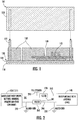
FIG. 1 is an exploded, side schematic view of an alarm; -
FIG. 2 is a schematic diagram of an isolation of a radio module in an alarm from electrical components of the alarm; -
FIG. 3 is a schematic circuit diagram of a filter for use in the isolation ofFIG. 2 ; -
FIG. 4 is a schematic circuit diagram of a filter for use in the isolation ofFIG. 2 ; -
FIG. 5 is a graphical depiction of communication performance of an alarm without an antenna, with an antenna but without isolation and with an antenna and isolation; -
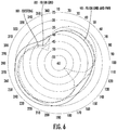
FIG. 6 is a graphical depiction of radiation patterns of an alarm with an antenna but without isolation, with an antenna and ground line filtering only and with an antenna and filtering on ground and power lines; and -
FIG. 7 is a graphical depiction of radiation patterns of an alarm with low pass filters of different reflection coefficients. - These and other advantages and features will become more apparent from the following description taken in conjunction with the drawings.
- As will be described below, an alarm is provided. The alarm includes a radio module where the alarm board and the radio module share power lines, ground lines (or planes) and communication lines (or communication signal lines). The ground on the alarm board, which is common to a smoke sensor, a carbon monoxide sensor, batteries and other similar electrical components, is separated from a radio ground using filter circuits and ferrite beads. In order to isolate the alarm ground and the radio ground only at the required frequency of operation while maintaining direct current (DC) continuity, low pass filter circuit in series with a ferrite bead are tuned to operate at appropriate frequencies with an insertion loss/gain of the filter circuits, an S21/S12 parameter, equal to 0dB and a reflection coefficient of the filter circuits, an S11/S22 parameter, in a range of about -40dB to -60dB or about -40dB to -100dB between the radio ground and the ground of the smoke and carbon monoxide sensors, the batteries and the other similar electrical components (i.e., the "alarm ground"). The ferrite bead is chosen to have a high reactance in the range of 150 ohms to 200 ohms at the operating frequency of the radio module. A similar filter can be implemented between the power lines from the alarm board to the radio board to improve the radio performance.
- With reference to
FIGS. 1 and 2 , an alarm ordetector 101 is provided and includes astructural backplane 110, acover 120 that is connectable to thestructural backplane 110 byguide bosses 111, analarm board assembly 130 that is supported on thestructural backplane 110 and acommunication module 140 that is indirectly supported on thestructural backplane 110 and includes anantenna 145. Thealarm board assembly 130 configured to perform one or more of alarm and detection operations and includes an alarm or first board (hereinafter referred to as a "first board") 131 andelectrical components 132 that are operably disposed on thefirst board 131 to execute the one or more of the alarm and detection operations. Theelectrical components 132 can include smoke, carbon monoxide or other sensors, power supply circuitry, sounders, speakers, etc., as may be present in a detection and alarm device. Thecommunication module 140 is configured to wirelessly communicate with one or more other alarms, detectors and related devices via theantenna 145. Theantenna 145 can include or be provided as a monopole antenna and thecommunication module 140 and theantenna 145 operate in a sub-GHz radio frequency (RF). - As shown in
FIG. 2 , the alarm ordetector 101 also includes apower source 210, an alarm or first ground (hereinafter referred to as a "first ground") 220, acommunication ground 230, afirst bus 240 and asecond bus 250. Thefirst bus 240 is electrically communicative with the alarm board assembly 130 (i.e., with the first board 131) and with thecommunication module 140. Thesecond bus 250 is electrically communicative with the alarm board assembly 130 (i.e., with the first board 131) and with thecommunication module 140. Thefirst bus 240 is tied to thefirst ground 220 and thecommunication ground 230. Thesecond bus 250 is tied to thepower source 210. - As shown in
FIG. 2 , the alarm ordetector 101 further includes isolation to improve a performance of thecommunication module 140 and theantenna 145. The isolation can be provided by afirst isolation element 260 that is disposed on thefirst bus 240 to isolate thealarm board assembly 130 and thefirst ground 220 from thecommunication ground 230 and thecommunication module 140. The isolation can alternatively be provided by a combination of thefirst isolation element 260 and asecond isolation element 270 that is disposed on thesecond bus 250 to isolate thepower source 210 from thecommunication module 140. - Explained differently, the alarm or
detector 101 is configured such that at least one of thealarm board assembly 130 or thefirst board 131 and thefirst ground 220 are isolated from thecommunication ground 230 and thecommunication module 140 and thecommunication module 140 is isolated from thepower source 210. - With continued reference to
FIG. 2 and with additional reference toFIGS. 3 and 4 , the first andsecond isolation elements 260 and 270 (seeFIG. 2 ) can each include afilter 301. Thefilter 301 has a reflection coefficient parameter of the filter, S11/S22 should be in the range of -40dB to -60dB or -40dB to -100dB and an insertion loss parameter, S12/S21 of about 0db across a bandwidth of an operating frequency of thecommunication module 140 and theantenna 145. For a low pass filter, a cut-off frequency of thefilter 301 is or should be slightly less than an operating frequency of thecommunication module 140 and theantenna 145 and, in a case of a low-pass filter, is or should be nearly equal to or slightly higher than the operating frequency of thecommunication module 140. By doing so, the filter is designed to pass all lower frequency signals between thefirst ground 220 and thecommunication ground 230 and any signal at the operating frequency is eliminated. When the monopole antenna radiates, thecommunication ground 230 also radiates to imitate a perfect dipole antenna. Since the radiation of a ground plane plays a major role in the performance of the monopole antenna, anisolated communication ground 230 is provided to aid in the performance of the antenna. Since thefirst ground 220 is shared by sensors, sounders and other components, they impact the radiation of the antenna negatively. Thefilter element 260 helps to isolate thefirst ground 220 so thecommunication ground 230 can act as a perfect monopole antenna ground and help in providing for better or improved radiation performance. - As shown in
FIGS. 3 and 4 , thefilter 301 is disposed between thefirst ground 220 and thecommunication ground 230 and is thus positioned as thefirst isolation element 260. The following description will refer to this case. This is done for purposes of clarity and brevity and it is to be understood that thesecond isolation element 270 may have a similar configuration. - The
filter 301 can include a series of one or more of ferrite beads and low pass filters. For example, as shown inFIG. 3 , thefilter 301 can include first and second impedance elements L1 and L2 disposed in series between thefirst ground 220 and thecommunication ground 230 as well as a first capacitor C1 in parallel with the first impedance element L1 and a second capacitor C2 in parallel with the second impedance element L2. As another example, as shown inFIG. 4 , thefilter 301 can include first and second impedance elements L1 and L2 disposed in series between thefirst ground 220 and thecommunication ground 230 as well as a first capacitor C1 and a resistor R1 in parallel with the first impedance element L1 to form afirst circuit element 410 and a second capacitor C2 in parallel with thefirst circuit element 410. - The ferrite bead is chosen to have high impedance in the range of 500 ohms to 1 kohms with high reactance in the range of 150 ohms to 200 ohms as this provides the high impedance isolation between the
communication ground 230 and thefirst ground 220. The filter is designed to be either a low pass filter with the cut-off frequency slightly lower than the cut-off frequency and for a high pass filter with the cut-off frequency slightly higher than the cut-off frequency. A low pass filter passes all signals lower than the cut-off frequency and blocks higher frequency signals. A high pass filter passes all signals higher than the cut-off frequency and blocks lower frequency signals. So it is essential to design the filter accordingly with the operating frequency of the radio in mind. - With reference to
FIG. 5 , enhancement of communication performance of the alarm ordetector 101 is illustrated in comparison to an alarm or detector without an antenna or isolation and in comparison to an alarm or detector with an antenna but without isolation. As shown inFIG. 5 , where the alarm ordetector 101 is provided with isolation (i.e., isolation provided by thefirst isolation element 260 and the second isolation element 270), the alarm ordetector 101 exhibits substantially improved communication performance as compared to the non-antenna and non-isolation case in terms of substantially increased range and improved power output on the radiation pattern and exhibits more improved communication performance as compared to the antenna without isolation case in terms of further increased range and substantial decreases in polar lobe effects. - With reference to
FIG. 6 , enhancement of radiation patterns of the alarm ordetector 101 is illustrated in comparison to an alarm or detector without any isolation. As shown inFIG. 6 , where the alarm ordetector 101 is provided with only the first isolation element 260 (HH - FB on GND), the alarm ordetector 101 exhibits improved radiation patterns as compared to the non-isolation case (HH - existing) in terms of decreased polar lobe effects and, where the alarm ordetector 101 is provided with the first andsecond isolation elements 260 and 270 (HH - FB on GND and PWR), the alarm ordetector 101 exhibits more improved radiation patterns as compared to the single-isolation case (HH - FB on GND) in terms of at least further decreases in polar lobe effects. - As shown in
FIG. 6 , the radiation pattern with and without isolation is shown. A radiation pattern is a polar plot of power output from the radio received at a given distance. The radiation pattern shown is measured at every 10 degree increments, higher the power output better communication range, lower the power output lower communication range. Ideally, for a Line of Sight communication where an alarm with a radio is communicating with another alarm with a radio without any obstruction in between them, thereby line of sight communication, the rule of thumb is that 6dB increase in radiated power out will yield twice the communication distance. - With reference to
FIG 7 , the radiation pattern of a radio operating at 926MHz with low pass filters of different reflection coefficients, S11 parameters is shown.FIG. 7 illustrates that the power out of the antenna is improved as the reflection coefficient decreases and becomes more negative in number. - Technical effects and benefits of the present disclosure are the provision of an alarm that uses a monopole antenna with improved or enhanced performance owing to isolation between the alarm ground and the radio ground so that the alarm meets specified range requirements (i.e., 100 meter open air range requirements).
- While the disclosure is provided in detail in connection with only a limited number of embodiments, it should be readily understood that the disclosure is not limited to such disclosed embodiments. Rather, the disclosure can be modified to incorporate any number of variations, alterations, substitutions or equivalent arrangements not heretofore described, but which are commensurate with the scope of the disclosure. Additionally, while various embodiments of the disclosure have been described, it is to be understood that the exemplary embodiment(s) may include only some of the described exemplary aspects. Accordingly, the disclosure is not to be seen as limited by the foregoing description, but is only limited by the scope of the appended claims.
Claims (15)
- An alarm or detector, comprising:an alarm board assembly (130) configured to perform one or more of alarm and detection operations; anda communication module (140) including an antenna (145) configured to communicate with one or more other alarms and detectors,wherein at least one of:the alarm board (130) and an alarm ground (220) are isolated from a communication ground (230) and the communication module (140); andthe communication module (140) is isolated from a power source (210).
- The alarm or detector according to claim 1, wherein the communication module (140) and the antenna (145) operate in a sub-GHz radio frequency.
- The alarm or detector according to claim 1 or 2, wherein only the alarm board (130) and the alarm ground (220) are isolated from the communication ground (230) and the communication module (140).
- The alarm or detector according to claim 1 or 2, wherein:the alarm board (130) and the alarm ground (220) are isolated from the communication ground (230) and the communication module (140), andthe communication module (140) is isolated from the power source (210).
- The alarm or detector according to any preceding claim, wherein:isolation of the alarm board (130) and the alarm ground (220) from the communication ground (230) and the communication module (140) is provided by a first filter,isolation between the communication module (140) and the power source (210) is provided by a second filter, andat least one of the first and second filters has one or more of:a reflection coefficient parameter close to about -100dB and an insertion loss parameter of about 0db across a bandwidth of an operating frequency of the communication module (140) and the antenna (145), anda cut-off frequency of the filter nearly equal to or slightly less than the operating frequency of the communication module (140) and the antenna (145).
- An alarm or detector, comprising:a first board (131) on which electrical components (132) are disposed;a communication module (140) including an antenna (145);a power source (210);a first ground (220);a communication ground (230);first and second buses (240, 250), each of which is electrically communicative with the first board (131) and the communication module (140), the first bus (240) being tied to the first ground (220) and the communication ground (230) and the second bus (250) being tied to the power source (210); andat least one of:a first isolation element (260) disposed on the first bus (240) to isolate the first board (131) and the first ground (220) from the communication ground (230) and the communication module (140); anda second isolation element (270) disposed on the second bus (250) to isolate the power source (210) from the communication module (140).
- The alarm or detector according to claim 6, wherein:the electrical components (132) are configured to execute one or more of alarm and detection operations, andthe communication module (140) is configured to communicate with one or more other alarms and detectors and the antenna (145) is configured to increase a range of the communication module (140).
- The alarm or detector according to claim 6 or 7, wherein the communication module (140) and the antenna (145) operate in a sub-GHz radio frequency.
- The alarm or detector according to claim 6, 7 or 8, wherein the alarm or detector comprises the first isolation element (260); and/or
wherein the alarm or detector comprises the first and second isolation elements (260, 270). - The alarm or detector according to any of claims 6 to 9, wherein the first and second isolation elements (260, 270) each comprise a filter (301).
- The alarm or detector according to claim 10, wherein the filter (301) has a reflection coefficient parameter close to about -100dB and an insertion loss parameter of about 0db across a bandwidth of an operating frequency of the communication module (140) and the antenna (145); and/or.
wherein a cut-off frequency of the filter (301) is nearly equal to or slightly less than an operating frequency of the communication module (140) and the antenna (145); and/or
wherein the filter (301) comprises a series of one or more of ferrite beads and low pass filters. - An alarm or detector, comprising:an alarm board assembly (130) configured to perform one or more of alarm and detection operations;a communication module (140) including an antenna (145) configured to communicate with one or more other alarms and detectors;a power source (210);an alarm ground (220);a communication ground (230);first and second buses (240, 250), each of which is electrically communicative with the alarm board assembly (130) and the communication module (140), the first bus (240) being tied to the alarm ground (220) and the communication ground (230) and the second bus (250) being tied to the power source (210); andone of:a first isolation element (260) disposed on the first bus (240) to isolate the alarm board assembly (130) and the alarm ground (220) from the communication ground (230) and the communication module (140), orthe first isolation element (260) and a second isolation element (270) disposed on the second bus (250) to isolate the power source (210) from the communication module (140).
- The alarm or detector according to claim 12, wherein the communication module (140) and the antenna (145) operate in a sub-GHz radio frequency.
- The alarm or detector according to claim 12 or 13, wherein the first and second isolation elements (260, 270) each comprise a filter (301).
- The alarm or detector according to claim 14, wherein the filter (301) has a reflection coefficient parameter close to about -100dB and an insertion loss parameter of about 0db across a bandwidth of an operating frequency of the communication module (140) and the antenna (145); and/or
wherein a cut-off frequency of the filter (301) is nearly equal to or slightly less than an operating frequency of the communication module (140) and the antenna (145); and/or
wherein the filter (301) comprises a series of one or more of ferrite beads and low pass filters.
Applications Claiming Priority (1)
| Application Number | Priority Date | Filing Date | Title |
|---|---|---|---|
| US201962934789P | 2019-11-13 | 2019-11-13 |
Publications (1)
| Publication Number | Publication Date |
|---|---|
| EP3822937A1 true EP3822937A1 (en) | 2021-05-19 |
Family
ID=73401428
Family Applications (1)
| Application Number | Title | Priority Date | Filing Date |
|---|---|---|---|
| EP20207256.7A Pending EP3822937A1 (en) | 2019-11-13 | 2020-11-12 | Alarm with enhanced radio performance by isolation of radio from alarm components |
Country Status (5)
| Country | Link |
|---|---|
| US (1) | US11514770B2 (en) |
| EP (1) | EP3822937A1 (en) |
| CN (1) | CN112803160A (en) |
| CA (1) | CA3098236A1 (en) |
| MX (1) | MX2020012110A (en) |
Citations (3)
| Publication number | Priority date | Publication date | Assignee | Title |
|---|---|---|---|---|
| US20080100463A1 (en) * | 2005-03-31 | 2008-05-01 | Harold Shirlee | Alarm shut off system |
| US20150083810A1 (en) * | 2013-09-22 | 2015-03-26 | Larry Ching | Rfid sensor tag and system for small output transducers,and related methods |
| WO2017196752A1 (en) * | 2016-05-12 | 2017-11-16 | Roost, Inc. | Controlling a smoke detector by regulating battery voltage |
Family Cites Families (29)
| Publication number | Priority date | Publication date | Assignee | Title |
|---|---|---|---|---|
| US3657714A (en) | 1970-06-10 | 1972-04-18 | Electro Devices Inc | Ground eliminator system |
| US4331952A (en) | 1980-09-22 | 1982-05-25 | American District Telegraph Company | Redundant sensor adapter |
| US5598169A (en) * | 1995-03-24 | 1997-01-28 | Lucent Technologies Inc. | Detector and modulator circuits for passive microwave links |
| US5933077A (en) | 1997-06-20 | 1999-08-03 | Wells Fargo Alarm Services, Inc. | Apparatus and method for detecting undesirable connections in a system |
| US6952165B2 (en) * | 2003-12-19 | 2005-10-04 | Honeywell International, Inc. | Concealed wireless sensor with external antenna |
| US7629880B2 (en) | 2004-03-09 | 2009-12-08 | Ingrid, Inc. | System, method and device for detecting a siren |
| US7561055B2 (en) | 2006-01-10 | 2009-07-14 | Guardian Industries Corp. | Rain sensor with capacitive-inclusive circuit |
| US9433750B2 (en) * | 2009-06-16 | 2016-09-06 | The Board Of Trustees Of The Leland Stanford Junior University | Method of making and using an apparatus for a locomotive micro-implant using active electromagnetic propulsion |
| WO2011114204A1 (en) | 2010-03-19 | 2011-09-22 | パナソニック電工株式会社 | Wireless apparatus, wireless abnormality notification system using same, and wireless remote control system |
| NL2006494C2 (en) | 2011-03-25 | 2012-09-26 | Astrea Intellectueel Eigendomsrecht B V | Isolator device for passing through a signal. |
| US9704360B2 (en) | 2013-03-15 | 2017-07-11 | OWL Enterprises, LLC | Occupancy-sensor wireless-security and lighting-control |
| US9685699B2 (en) * | 2013-05-21 | 2017-06-20 | Microsoft Technology Licensing, Llc | Integrated antenna for wireless communications and wireless charging |
| US9581342B2 (en) | 2014-03-28 | 2017-02-28 | Google Inc. | Mounting stand for multi-sensing environmental control device |
| US9609462B2 (en) | 2014-03-28 | 2017-03-28 | Google Inc. | Facilitating radio frequency communications among environmental control system components |
| US9865920B1 (en) * | 2014-08-27 | 2018-01-09 | Amazon Technologies, Inc. | Antenna isolation in a multi-band antenna system |
| CN204238786U (en) | 2014-11-12 | 2015-04-01 | 重庆宁来科贸有限公司 | A kind of touch early warning security security door |
| CN204238787U (en) | 2014-11-12 | 2015-04-01 | 重庆宁来科贸有限公司 | A kind of early warning guarding door of having electronic monitor |
| US9794522B2 (en) | 2015-02-06 | 2017-10-17 | Google Inc. | Systems, methods, and devices for managing coexistence of multiple transceiver devices by optimizing component layout |
| US9396633B1 (en) | 2015-06-14 | 2016-07-19 | Google Inc. | Systems, methods, and devices for managing coexistence of multiple transceiver devices by optimizing component layout |
| TWI549362B (en) * | 2015-06-15 | 2016-09-11 | 泓博無線通訊技術有限公司 | A slot antenna with reducing electromagnetic wave absorption ratio |
| CN204926359U (en) | 2015-09-20 | 2015-12-30 | 重庆宁来科贸有限公司 | Anti -theft device of self -checking type area early warning |
| CN106781175A (en) | 2015-11-25 | 2017-05-31 | 李福霞 | A kind of video image fire detection device based on SoPC |
| CN107124098A (en) * | 2016-02-24 | 2017-09-01 | 张生兰 | Isolated from power device and TD-SCDMA terminals |
| CN206773904U (en) * | 2017-05-23 | 2017-12-19 | 武汉拓宝科技股份有限公司 | A kind of general detector base based on wireless internet of things communication |
| WO2019107081A1 (en) * | 2017-11-30 | 2019-06-06 | 株式会社村田製作所 | Filter circuit, filter circuit element, and multiplexer/demultiplexer |
| US10319213B1 (en) | 2018-06-27 | 2019-06-11 | Google Llc | Thermal management in smart doorbells |
| FR3083859B1 (en) * | 2018-07-12 | 2020-06-12 | Continental Automotive France | RADIOELECTRIC TRANSMISSION SENSOR FOR VEHICLE WHEEL COMPRISING A TWO-MODE ANTENNA CIRCUIT |
| US20200076488A1 (en) * | 2018-08-30 | 2020-03-05 | Skyworks Solutions, Inc. | Beamforming communication systems with sensor aided beam management |
| CA3145860A1 (en) * | 2019-07-03 | 2021-01-07 | Earth Networks, Inc. | Antenna for use with lightning detection sensor |
-
2020
- 2020-10-29 US US17/084,063 patent/US11514770B2/en active Active
- 2020-11-06 CA CA3098236A patent/CA3098236A1/en active Pending
- 2020-11-12 MX MX2020012110A patent/MX2020012110A/en unknown
- 2020-11-12 EP EP20207256.7A patent/EP3822937A1/en active Pending
- 2020-11-12 CN CN202011261470.5A patent/CN112803160A/en active Pending
Patent Citations (3)
| Publication number | Priority date | Publication date | Assignee | Title |
|---|---|---|---|---|
| US20080100463A1 (en) * | 2005-03-31 | 2008-05-01 | Harold Shirlee | Alarm shut off system |
| US20150083810A1 (en) * | 2013-09-22 | 2015-03-26 | Larry Ching | Rfid sensor tag and system for small output transducers,and related methods |
| WO2017196752A1 (en) * | 2016-05-12 | 2017-11-16 | Roost, Inc. | Controlling a smoke detector by regulating battery voltage |
Also Published As
| Publication number | Publication date |
|---|---|
| CA3098236A1 (en) | 2021-05-13 |
| US11514770B2 (en) | 2022-11-29 |
| MX2020012110A (en) | 2021-05-14 |
| US20210142647A1 (en) | 2021-05-13 |
| CN112803160A (en) | 2021-05-14 |
Similar Documents
| Publication | Publication Date | Title |
|---|---|---|
| US10033113B2 (en) | Antenna device and electronic apparatus | |
| EP3767742B1 (en) | Antenna device and mobile terminal | |
| CN209860131U (en) | Electronic device | |
| US10741908B2 (en) | Antenna system and antenna module with reduced interference between radiating patterns | |
| KR101634274B1 (en) | Antenna structrure | |
| US20150042524A1 (en) | Antenna | |
| EP2190057B1 (en) | Glass antenna and window glass for vehicle | |
| WO2019071848A1 (en) | Antenna device and mobile terminal | |
| US20080287084A1 (en) | Antenna Device and Portable Radio Communication Device Comprising Such Antenna Device | |
| US20190312340A1 (en) | Wearable apparatus and antenna control method thereof | |
| EP3220478B1 (en) | Diversity antenna | |
| EP3185354A1 (en) | Antenna component and electronic device | |
| US20040053635A1 (en) | System for controlling transmitting power of antenna | |
| EP3709441A1 (en) | Multi-frequency antenna and mobile terminal | |
| KR102527871B1 (en) | Antenna assembly | |
| US11514770B2 (en) | Alarm with enhanced radio performance by isolation of radio from alarm components | |
| US11627420B2 (en) | Loop antenna for hearing aid | |
| US20200014108A1 (en) | Antenna device | |
| EP3361563B1 (en) | Glass antenna and window glass for vehicle | |
| WO2017185493A1 (en) | Antenna apparatus and mobile terminal | |
| EP1973196A1 (en) | Antenna device and portable radio communication device comprising such antenna device | |
| CN110459860B (en) | Rear shell assembly and electronic equipment | |
| CN112751195A (en) | Terminal antenna system and mobile terminal | |
| US10326536B2 (en) | Electromagnetic device for damping a first circuit with respect to a second circuit | |
| EP3796565B1 (en) | Electronic device |
Legal Events
| Date | Code | Title | Description |
|---|---|---|---|
| PUAI | Public reference made under article 153(3) epc to a published international application that has entered the european phase |
Free format text: ORIGINAL CODE: 0009012 |
|
| STAA | Information on the status of an ep patent application or granted ep patent |
Free format text: STATUS: THE APPLICATION HAS BEEN PUBLISHED |
|
| AK | Designated contracting states |
Kind code of ref document: A1 Designated state(s): AL AT BE BG CH CY CZ DE DK EE ES FI FR GB GR HR HU IE IS IT LI LT LU LV MC MK MT NL NO PL PT RO RS SE SI SK SM TR |
|
| STAA | Information on the status of an ep patent application or granted ep patent |
Free format text: STATUS: REQUEST FOR EXAMINATION WAS MADE |
|
| 17P | Request for examination filed |
Effective date: 20211119 |
|
| RBV | Designated contracting states (corrected) |
Designated state(s): AL AT BE BG CH CY CZ DE DK EE ES FI FR GB GR HR HU IE IS IT LI LT LU LV MC MK MT NL NO PL PT RO RS SE SI SK SM TR |
|
| STAA | Information on the status of an ep patent application or granted ep patent |
Free format text: STATUS: EXAMINATION IS IN PROGRESS |
|
| 17Q | First examination report despatched |
Effective date: 20220517 |
|
| P01 | Opt-out of the competence of the unified patent court (upc) registered |
Effective date: 20230527 |