EP3822916A1 - Image compression using normalizing flows - Google Patents
Image compression using normalizing flows Download PDFInfo
- Publication number
- EP3822916A1 EP3822916A1 EP20198064.6A EP20198064A EP3822916A1 EP 3822916 A1 EP3822916 A1 EP 3822916A1 EP 20198064 A EP20198064 A EP 20198064A EP 3822916 A1 EP3822916 A1 EP 3822916A1
- Authority
- EP
- European Patent Office
- Prior art keywords
- input image
- latent space
- space representation
- image
- software code
- Prior art date
- Legal status (The legal status is an assumption and is not a legal conclusion. Google has not performed a legal analysis and makes no representation as to the accuracy of the status listed.)
- Pending
Links
Images



Classifications
-
- G—PHYSICS
- G06—COMPUTING OR CALCULATING; COUNTING
- G06T—IMAGE DATA PROCESSING OR GENERATION, IN GENERAL
- G06T9/00—Image coding
- G06T9/002—Image coding using neural networks
-
- H—ELECTRICITY
- H04—ELECTRIC COMMUNICATION TECHNIQUE
- H04N—PICTORIAL COMMUNICATION, e.g. TELEVISION
- H04N19/00—Methods or arrangements for coding, decoding, compressing or decompressing digital video signals
- H04N19/10—Methods or arrangements for coding, decoding, compressing or decompressing digital video signals using adaptive coding
- H04N19/102—Methods or arrangements for coding, decoding, compressing or decompressing digital video signals using adaptive coding characterised by the element, parameter or selection affected or controlled by the adaptive coding
- H04N19/124—Quantisation
- H04N19/126—Details of normalisation or weighting functions, e.g. normalisation matrices or variable uniform quantisers
-
- H—ELECTRICITY
- H04—ELECTRIC COMMUNICATION TECHNIQUE
- H04N—PICTORIAL COMMUNICATION, e.g. TELEVISION
- H04N19/00—Methods or arrangements for coding, decoding, compressing or decompressing digital video signals
- H04N19/60—Methods or arrangements for coding, decoding, compressing or decompressing digital video signals using transform coding
-
- H—ELECTRICITY
- H04—ELECTRIC COMMUNICATION TECHNIQUE
- H04N—PICTORIAL COMMUNICATION, e.g. TELEVISION
- H04N19/00—Methods or arrangements for coding, decoding, compressing or decompressing digital video signals
- H04N19/90—Methods or arrangements for coding, decoding, compressing or decompressing digital video signals using coding techniques not provided for in groups H04N19/10-H04N19/85, e.g. fractals
-
- H—ELECTRICITY
- H04—ELECTRIC COMMUNICATION TECHNIQUE
- H04N—PICTORIAL COMMUNICATION, e.g. TELEVISION
- H04N19/00—Methods or arrangements for coding, decoding, compressing or decompressing digital video signals
- H04N19/90—Methods or arrangements for coding, decoding, compressing or decompressing digital video signals using coding techniques not provided for in groups H04N19/10-H04N19/85, e.g. fractals
- H04N19/91—Entropy coding, e.g. variable length coding [VLC] or arithmetic coding
Definitions
- neural image compression has made significant progress with deep learning based approaches. There are two key aspects in neural based image compression. First a mapping from image space to a latent space must be learned. Second, a probability needs to be learned in this new space to allow entropy coding of the latents.
- the invention comprises: A method comprising:
- the method wherein the probability density function is obtained based on the normalizing flow mapping of the latent space representation of the input image, and wherein the normalizing flow mapping comprises a bijective mapping of the latent space representation of the input image.
- the method further comprising: transforming, using a neural network (NN) encoder, the input image to the latent space representation of the input image.
- NN neural network
- the method wherein the normalizing flow mapping of the latent space representation of the input image maps the latent space representation onto a constrained probability density distribution.
- the method wherein the constrained probability density distribution comprises a Gaussian distribution.
- the method further comprising: converting, using an NN decoder, the bitstream into the output image.
- the method wherein the normalizing flow mapping of the input image transforms the input image to the latent space representation of the input image.
- the normalizing flow mapping of the input image is a first normalizing flow mapping
- the hardware processor further executes the software code to perform a second normalizing flow mapping to convert the bitstream into the output image.
- a probability density distribution of the latent space representation of the input image is a constrained probability density distribution.
- the method wherein the probability density distribution of the latent space representation of the input image comprises a Gaussian distribution.
- An image compression system comprising:
- An image compression system comprising:
- the image compression system wherein the probability density function is obtained based on the normalizing flow mapping of the latent space representation of the input image, and wherein the normalizing flow mapping comprises a bijective mapping of the latent space representation of the input image.
- the image compression system wherein the software code includes a neural network (NN) encoder, and wherein the hardware processor is further configured to execute the software code to utilize the NN encoder to transform the input image to the latent space representation of the input image.
- NN neural network
- the image compression system wherein the normalizing flow mapping maps the latent space representation onto a constrained probability density distribution.
- the image compression system wherein the constrained probability density distribution comprises a Gaussian distribution.
- the image compression system wherein the software code further includes a NN decoder, and wherein the hardware processor is further configured to execute the software code to utilize the NN decoder to convert the bitstream into the output image.
- the image compression system wherein the normalizing flow mapping of the input image transforms the input image to the latent space representation of the input image.
- the image compression system wherein the normalizing flow mapping of the input image is a first normalizing flow mapping, and wherein the hardware processor is further configured to execute the software code to perform a second normalizing flow mapping to convert the bitstream into the output image.
- the image compression system wherein a probability density distribution of the latent space representation of the input image is a constrained probability density distribution.
- the image compression system wherein the probability density distribution of the latent space representation of the input image comprises a Gaussian distribution.
- the invention comprises: A method for use by an image compression system including a computing platform having a hardware processor and a system memory storing a software code, the method comprising:
- the method wherein the probability density function is obtained based on the normalizing flow mapping of the latent space representation of the input image, and wherein the normalizing flow mapping comprises a bijective mapping of the latent space representation of the input image.
- the method wherein the software code includes a neural network (NN) encoder, and wherein the hardware processor further executes the software code to utilize the NN encoder to transform the input image to the latent space representation of the input image.
- NN neural network
- the method wherein the normalizing flow mapping of the latent space representation of the input image maps the latent space representation onto a constrained probability density distribution.
- the method wherein the constrained probability density distribution comprises a Gaussian distribution.
- the software code further includes an NN decoder
- the hardware processor further executes the software code to utilize the NN decoder to convert the bitstream into the output image.
- the method wherein the normalizing flow mapping of the input image transforms the input image to the latent space representation of the input image.
- the normalizing flow mapping of the input image is a first normalizing flow mapping
- the hardware processor further executes the software code to perform a second normalizing flow mapping to convert the bitstream into the output image.
- a probability density distribution of the latent space representation of the input image is a constrained probability density distribution.
- An image compression system comprising:
- the present application discloses systems and methods for performing image compression using normalizing flows that overcome the drawbacks and deficiencies in the conventional art. It is noted that, in some implementations, the methods disclosed by the present application may be performed as substantially automated processes by substantially automated systems. It is further noted that, as used in the present application, the terms “automation,” “automated”, and “automating” refer to systems and processes that do not require the participation of a human user, such as a system operator. Although, in some implementations, a human system operator or administrator may review the performance of the automated systems described herein, that human involvement is optional. Thus, the methods described in the present application may be performed under the control of hardware processing components of the disclosed automated systems.
- an artificial neural network also known simply as a neural network (hereinafter "NN")
- NN is a type of machine learning framework in which patterns or learned representations of observed data are processed using highly connected computational layers that map the relationship between inputs and outputs.
- a “deep neural network,” in the context of deep learning, may refer to a neural network that utilizes multiple hidden layers between input and output layers, which may allow for learning based on features not explicitly defined in raw data.
- a feature labeled as an NN refers to a deep neural network.
- CNNs convolutional NNs
- CNNs convolutional NNs
- layers that apply a convolution operation to an input to the CNN
- CNNs may be used to make predictions about new data based on past examples or “training data.”
- training data may be utilized to perform image processing or natural-language processing.
- Figure 1 shows a diagram of an exemplary system for performing image compression using normalizing flows, according to one implementation.
- image compression system 100 may be implemented using a computer server accessible over a local area network (LAN) or may be implemented as cloud-based system.
- image compression system 100 includes computing platform 102 having hardware processor 104, and system memory 106 implemented as a non-transitory storage device.
- system memory 106 stores software code 110.
- image compression system 100 is implemented within a use environment including communication network 108 and user system 120 including display 122 configured to be utilized by a user 124. Also shown in Figure 1 are network communication links 128 interactively connecting user system 120 and image compression system 100 via communication network 108, input image 130, and output image 138 corresponding to input image 130 and produced using software code 110.
- system memory 106 may take the form of any computer-readable non-transitory storage medium.
- computer-readable non-transitory storage medium refers to any medium, excluding a carrier wave or other transitory signal that provides instructions to hardware processor 104 of computing platform 102.
- a computer-readable non-transitory medium may correspond to various types of media, such as volatile media and non-volatile media, for example.
- Volatile media may include dynamic memory, such as dynamic random access memory (dynamic RAM), while non-volatile memory may include optical, magnetic, or electrostatic storage devices.
- Common forms of computer-readable non-transitory media include, for example, optical discs, RAM, programmable read-only memory (PROM), erasable PROM (EPROM), and FLASH memory.
- image compression system 100 may include one or more computing platforms 102, such as computer servers for example, which may be co-located, or may form an interactively linked but distributed system, such as a cloud-based system, for instance.
- computing platforms 102 such as computer servers for example, which may be co-located, or may form an interactively linked but distributed system, such as a cloud-based system, for instance.
- hardware processor 104 and system memory 106 may correspond to distributed processor and memory resources within image compression system 100.
- various features of software code 110 such as one or more of the features described below by reference to Figures 2 , 4 , and 5 , may be stored and/or executed using the distributed memory and/or processor resources of image compression system 100.
- computing platform 102 may correspond to one or more web servers, accessible over a packet-switched network such as the Internet, for example.
- computing platform 102 may correspond to one or more computer servers supporting a wide area network (WAN), a LAN, or included in another type of limited distribution or private network.
- WAN wide area network
- LAN local area network
- user system 120 is shown as a desktop computer in Figure 1 , that representation is also provided merely as an example. More generally, user system 120 may be any suitable mobile or stationary computing device or system that implements data processing capabilities sufficient to provide a user interface, support connections to communication network 108, and implement the functionality ascribed to user system 120 herein. For example, in other implementations, user system 120 may take the form of a laptop computer, tablet computer, or smartphone, for example. User 124 may utilize user system 120 to interact with image compression system 100 to use software code 110, executed by hardware processor 104, to produce output image 138 corresponding to input image 130.
- output image 138 when generated using software code 110, may be stored in system memory 106 and/or may be copied to non-volatile storage. Alternatively, or in addition, as shown in Figure 1 , in some implementations, output image 138 may be sent to user system 120 including display 122, for example by being transferred via network communication links 128 of communication network 108.
- display 122 may be physically integrated with user system 120 or may be communicatively coupled to but physically separate from user system 120.
- display 122 will typically be integrated with user system 120.
- display 122 may take the form of a monitor separate from user system 120 in the form of a computer tower.
- display 122 may be implemented as a liquid crystal display (LCD), a light-emitting diode (LED) display, an organic light-emitting diode (OLED) display, or any other suitable display screen that performs a physical transformation of signals to light.
- LCD liquid crystal display
- LED light-emitting diode
- OLED organic light-emitting diode
- the objective of lossy image compression is to find a mapping or encoding function ⁇ : x ⁇ y from the image space x to a latent space representation y and its reverse mapping or decoding function ⁇ : y ⁇ x back to the original image space.
- a mapping and reverse mapping is performed with the competing constraints that, on the one hand, the latent representation should occupy as little storage as possible while, on the other hand, the reconstructed image, i.e., output image 138, should closely resemble the original image, i.e., input image 130.
- this mapping is realized with a neural encoder-decoder pair, where the bottleneck values constitute the latent representation.
- Equation 1 corresponds to the length of the bitstream needed to encode the quantized representation ⁇ , based on a learned entropy model over the unknown distribution of natural images p x .
- the weight ⁇ steers the rate distortion trade-off, e.g., reducing ⁇ leads to a higher compression rate at the cost of a larger distortion of output image 138.
- a normalizing flow refers to the transformation of a probability density as the result of a series of invertible mappings, such as bijective mappings, for example.
- the objective is to map a simple distribution to a more complex one. This is done through a change of variable.
- p Y y p Z f z det ⁇ f x ⁇ x .
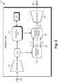
- Figure 2 shows exemplary software code 210 suitable for execution by hardware processor 104 of image compression system 100, in Figure 1 , according to one implementation.
- software code 210 includes NN encoder 212 configured to transform input image 230 to latent space representation 232 of input image 230, and normalizing flow 214 configured to produce normalizing flow mapping 234 of latent space representation 232.
- Software code 210 also includes quantization module 216 configured to quantize latent space representation 232.
- quantization refers to transforming continuous values into a discrete set of values before entropy coding. Quantization is generally done by dividing the original values by some quantization step and then rounding the result. The larger the quantization step the more information is lost.
- Quantization module 216 quantizes latent space representation 232 to produce multiple quantized latents 236, which are then entropy encoded by bitstream generation module 240 using a probability density function of latent space representation 232 obtained based on normalizing flow mapping 234, to produce bitstream 242.
- software code 210 includes NN decoder 218 configured to receive bitstream 242 and to produce output image 238 corresponding to input image 230.
- Input image 230 and output image 238 correspond respectively in general to input image 130 and output image 138, in Figure 1 , and those features may share any of the characteristics attributed to either corresponding feature by the present disclosure.
- software code 210 corresponds in general to software code 110, and those features may share the characteristics attributed to either corresponding feature by the present disclosure. That is to say, like software code 210, software code 110 may include NN encoder 212, normalizing flow 214, quantization module 216, bitstream generation module 240, and NN decoder 218.
- normalizing flow 214 is depicted conceptually because the specific architecture of normalizing flow 214 may vary, and in some implementations, may include several hierarchical levels.
- normalizing flow mapping 234 performed by normalizing flow 214 may be a bijective mapping of latent space representation 232 of input image 130/230.
- Figure 3 shows flowchart 350 presenting an exemplary method for performing image compression using normalizing flows, according to one implementation.
- flowchart 350 presenting an exemplary method for performing image compression using normalizing flows, according to one implementation.
- flowchart 350 begins with receiving input image 130/230 (action 351).
- user 124 may utilize user system 120 to interact with image compression system 100 in order to produce output image 138/238 corresponding to input image 130/230, which may be a digital photograph or one or more video frames, for instance.
- user 124 may transmit input image 130/230 from user system 120 to image compression system 100 via communication network 108 and network communication links 128.
- input image 130/230 may be received from a third party source, or may be stored in system memory 106.
- Input image 130/230 may be received by NN encoder 212 of software code 110/210, executed by hardware processor 104.
- Flowchart 350 continues with transforming input image 130/230 to latent space representation 232 of input image 130/230 (action 352).
- the transformation of input image 130/230 to latent space representation 232 of input image 130/230 may be performed by NN encoder 212 of software code 110/210, executed by hardware processor 104, and using any neural encoding techniques known in the art.
- Flowchart 350 continues with quantizing latent space representation 232 of input image 130/230 to produce quantized latents 236 (action 353).
- the quantization of latent space representation 232 of input image 130/230 to produce quantized latents 236 may be performed by quantization module 216 of software code 110/210, executed by hardware processor 104.
- the quantization of latent space representation 232 in action 353 may be performed using any one of several known quantization techniques. For example, in one implementation, quantization may be performed using simple rounding. It is emphasized that the quantization performed in action 353 is performed on latent space representation 232 that is provided as an output by NN encoder 212 directly to quantization module 216.
- flowchart 350 continues with encoding quantized latents 236 using a probability density function of latent space representation 232 of input image 130/230 that is obtained based on normalizing flow mapping 234 of latent space representation 232 of input image 130/230, to generate bitstream 242 (action 354).
- Quantized latents 236 may be entropy encoded by bitstream generation module 240 of software code 110/210, for example, executed by hardware processor 104.
- normalizing flow mapping 234 is used to map the latents y of latent space representation 232 into normalizing flow mapping 234 that has a simple probability density distribution as the result being constrained. That is to say, normalizing flow mapping 234 of latent space representation 232 of input image 130/230 maps latent space representation 232 onto a constrained probability density distribution.
- the probability density distribution of normalizing flow mapping 234 may be constrained to be Gaussian, although other distributions having other constraints may be used instead of a Gaussian distribution.
- the normalizing flow 214 is trained to minimize the rate distortion loss term in Equation 1 on a dataset of images.
- Normalizing flow mapping 234 makes it possible to obtain an estimate of the probability density function for any latent y, which can be used for entropy coding of quantized latents 236 by bitstream generation module 240.
- the probability density function for latent space representation 232 must typically be estimated for each of quantized latents 236 individually. By way of example, independently encoding each dimension (or channel) of the latents y is considered.
- ⁇ 1 ⁇ 2.
- flowchart 350 can conclude with converting bitstream 242 into output image 138/238 corresponding to input image 130/230 (action 355).
- the conversion of bitstream 242 into output image 138/238 may be performed by NN decoder 218 of software code 110/210, executed by hardware processor 104, and using any neural decoding techniques known in the art.
- optional action 356 shown in Figure 3 is discussed below after the alternative implementations of software code 110 shown by Figure 4 and Figure 5 are described.
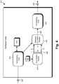
- Figure 4 shows exemplary software code 410 suitable for execution by hardware processor 104 of image compression system 100, in Figure 1 , according to another implementation.
- software code 410 includes first normalizing flow 414 configured to transform input image 430 to latent space representation 432 of input image 430.
- Software code 410 also includes quantization module 416 configured to quantize latent space representation 432 to produce multiple quantized latents 436, which are then entropy encoded by bitstream generation module 440 using a probability density function of latent space representation 432 obtained based on first normalizing flow mapping 434 to produce bitstream 442.
- software code 410 includes second normalizing flow 444 configured to receive bitstream 442 and to perform a second normalizing flow mapping on bitstream 442 to produce output image 438 corresponding to input image 430.
- Input image 430 and output image 438 correspond respectively in general to input image 130 and output image 138, in Figure 1 , and those features may share any of the characteristics attributed to either corresponding feature by the present disclosure.
- software code 410 corresponds in general to software code 110, and those features may share the characteristics attributed to either corresponding feature by the present disclosure. That is to say, like software code 410, software code 110 may include first normalizing flow 414, quantization module 416, bitstream generation module 440, and second normalizing flow 444.
- first normalizing flow 414 and second normalizing flow 444 are depicted conceptually because the specific architectures of first and second normalizing flows 414 and 444 may vary, and in some implementations, may include several hierarchical levels. It is further noted that first normalizing flow mapping 434 performed by first normalizing flow 414 may be a bijective mapping of latent space representation 432 of input image 130/430.
- flowchart 350 begins with receiving input image 130/430 (action 351).
- user 124 may utilize user system 120 to interact with image compression system 100 in order to produce output image 138/438 corresponding to input image 130/430, which may be a digital photograph or one or more video frames, for instance.
- user 124 may transmit input image 130/430 from user system 120 to image compression system 100 via communication network 108 and network communication links 128.
- input image 130/430 may be received from a third party source, or may be stored in system memory 106.
- Input image 130/430 may be received by first normalizing flow 414 of software code 110/410, executed by hardware processor 104.
- Flowchart 350 continues with transforming input image 130/430 to latent space representation 432 of input image 130/430 (action 352).
- the transformation of input image 130/430 to latent space representation 432 of input image 130/430 may be performed by first normalizing flow 414 of software code 110/410, executed by hardware processor 104, and using first normalizing flow mapping 434 of input image 130/430.
- first normalizing flow 414 may be hierarchical to allow a coarse to fine encoding. It is noted that first normalizing flow 414 is trained to minimize the rate distortion loss term in Equation 1 on a dataset of images.
- Flowchart 350 continues with quantizing latent space representation 432 of input image 130/430 to produce quantized latents 436 (action 353).
- the quantization of latent space representation 432 of input image 130/430 to produce quantized latents 436 may be performed by quantization module 416 of software code 110/410, executed by hardware processor 104.
- the quantization of latent space representation 432 in action 453 may be performed using any one of several known quantization techniques. For example, in one implementation, quantization may be performed using simple rounding.
- the quantization performed in action 353 is performed on latent space representation 432 of input image 130/430 that is provided as an output by first normalizing flow 414, in contrast to latent space representation 232 provided as an output by NN encoder 212, in Figure 2 .
- flowchart 350 continues with encoding quantized latents 436 using a probability density function of latent space representation 432 of input image 130/430 that is obtained based on first normalizing flow mapping 434 of input image 130/430, to generate bitstream 442 (action 354).
- Quantized latents 436 may be entropy encoded by bitstream generation module 440 of software code 110/410, for example, executed by hardware processor 104.
- First normalizing flow 414 is used to transform input image 130/430 into latent space representation 432 that has a simple probability density distribution, in action 352, as the result of first normalizing flow mapping 434 being constrained. That is to say, first normalizing flow mapping 434 of latent space representation 432 of input image 130/430 maps latent space representation 432 onto a constrained probability density distribution.
- the probability density distribution of first normalizing flow mapping 434 may be constrained to be Gaussian, although other distributions having other constraints may be used instead of a Gaussian distribution.
- flowchart 350 can conclude with converting bitstream 442 into output image 138/438 corresponding to input image 130/430 (action 355).
- the conversion of bitstream 442 into output image 138/438 may be performed as a normalizing flow mapping by second normalizing flow 444 of software code 110/410, executed by hardware processor 104.
- optional action 356 shown in Figure 3 is discussed below after the alternative implementation of software code 110 shown by Figure 5 is described.
- Figure 5 shows exemplary software code 510 suitable for execution by hardware processor 104 of image compression system 100, in Figure 1 , according to yet another implementation.
- software code 510 includes first normalizing flow 514 configured to use the output provided by NN encoder 512 to transform input image 530 to latent space representation 532 of input image 530 based on first normalizing flow mapping 534.
- Software code 510 also includes quantization module 516 configured to quantize latent space representation 532 to produce multiple quantized latents 536, which are then entropy encoded by bitstream generation module 540 using a probability density function of latent space representation 532 obtained based on first normalizing flow mapping 534, to produce bitstream 542.
- software code 510 includes second normalizing flow 544 configured to receive bitstream 542 and to perform a normalizing flow mapping on bitstream 542 to produce second normalizing flow mapping 546, as well as NN decoder 518. It is noted that software code 510 converts bitstream 542 into output image 538 corresponding to input image 530 using NN decoder 518 and second normalizing flow mapping 546 produced by second normalizing flow 544.
- Input image 530 and output image 538 correspond respectively in general to input image 130 and output image 138, in Figure 1 , and those features may share any of the characteristics attributed to either corresponding feature by the present disclosure.
- software code 510 corresponds in general to software code 110, and those features may share the characteristics attributed to either corresponding feature by the present disclosure. That is to say, like software code 510, software code 110 may include NN encoder 512, first normalizing flow 514, quantization module 516, bitstream generation module 540, second normalizing flow 544, and NN decoder 518.
- first normalizing flow 514 and second normalizing flow 544 are depicted conceptually because the specific architectures of first and second normalizing flows 514 and 544 may vary, and in some implementations, may include several hierarchical levels.
- first normalizing flow mapping 534 performed by first normalizing flow 514 may be a bijective mapping of latent space representation 532 of input image 130/530.
- flowchart 550 begins with receiving input image 130/530 (action 351).
- Input image 130/530 may be received by NN encoder 512 of software code 110/510, executed by hardware processor 104.
- Flowchart 350 continues with transforming input image 130/530 to latent space representation 532 of input image 130/530 (action 352).
- the transformation of input image 130/530 to latent space representation 532 of input image 130/530 may be performed using first normalized flow mapping 534 of the output of NN encoder 512 by first normalizing flow 514 of software code 110/510, executed by hardware processor 504.
- yet another approach for image compression is to utilize an autoencoder pair, i.e., NN encoder 512 and NN decoder 518 in combination with first and second normalizing flows 514 and 544.
- NN encoder 512 may serve to reduce the dimensionality of input image 130/530 before first normalizing flow 514.
- autoencoders are well understood and at the present time they have more flexibility than normalizing flows, which can be beneficial for image compression.
- Flowchart 350 continues with quantizing latent space representation 532 of input image 130/530 to produce quantized latents 536 (action 353).
- the quantization of latent space representation 532 of input image 130/530 to produce quantized latents 536 may be performed by quantization module 516 of software code 110/510, executed by hardware processor 104.
- the quantization of latent space representation 532 in action 353 may be performed using any one of several known quantization techniques. For example, in one implementation, quantization may be performed using simple rounding.
- the quantization performed in action 353 is performed on latent space representation 532 of input image 130/530 provided as an output by first normalizing flow 514, in contrast to latent space representation 232 provided as an output to quantization module 216 by NN encoder 212, in Figure 2 .
- flowchart 350 continues with encoding quantized latents 536 using a probability density function of latent space representation 532 of input image 130/530 that is obtained based on first normalizing flow mapping 534, to generate bitstream 542 (action 354).
- Quantized latents 536 may be entropy encoded by bitstream generation module 540 of software code 110/510, for example, executed by hardware processor 104.
- First normalizing flow 514 is used to transform the output of NN encoder 512 into latent space representation 532 of input image 130/530 that has a simple probability density distribution, in action 352, as the result of first normalizing flow mapping 534 being constrained. That is to say, first normalizing flow mapping 534 of latent space representation 532 of input image 130/530 maps latent space representation 532 onto a constrained probability density distribution.
- the probability density distribution of first normalizing flow mapping 534 may be constrained to be Gaussian, although other distributions having other constraints may be used instead of a Gaussian distribution.
- Flowchart 350 continues with converting bitstream 542 into output image 138/538 corresponding to input image 130/530 (action 355).
- the conversion of bitstream 542 into output image 138/538 may be performed using normalizing flow mapping 546 of bitstream 542 by second normalizing flow 544, of software code 110/510, executed by hardware processor 104, and using NN decoder 518 of software code 110/510, also executed by hardware processor 104.
- flowchart 350 can conclude with action 355.
- the method outlined by flowchart 350 may continue and conclude with rendering output image 138 on a display, such as display 122 of user system 120 (action 356).
- display 122 may be implemented as an LCD, LED display, or an OLED display, for example.
- display 122 may take the form of a high-definition (HD) display, or an Ultra HD display such as a 4K or 8K resolution display.
- HD high-definition
- Ultra HD such as a 4K or 8K resolution display.
- user system 120 including display 122 may be integrated with image compression system 100 such that display 122 may be controlled by hardware processor 104 of computing platform 102.
- software code 110 may be stored on a computer-readable non-transitory medium, and may be accessible to the hardware processing resources of user system 120.
- the rendering of output image 138 on display 122 may be performed by software code 110, executed either by hardware processor 104 of computing platform 102, or by a hardware processor of user system 120.
- hardware processor 104 may execute software code 110/210/410/510 to perform actions 351, 352, 353, 354, and 355, or actions 351, 352, 353, 354, 355, and 356, in an automated process from which human involvement may be omitted.
- the present application discloses systems and methods for performing image compression using normalizing flows that overcome the drawbacks and deficiencies in the conventional art. Improvements conferred by the present normalizing flow based image compression solution over the conventional state-of-the-art include a wider range of quality levels than autoencoder based image compression, going from low bitrates to near lossless quality level.
- the bijective mappings performed by the normalizing flows disclosed herein cause compressed images to always be mapped to the same point. Consequently, when compressing an image multiple times, the reconstruction quality and the bit rate advantageously remain constant for normalizing flows.
Landscapes
- Engineering & Computer Science (AREA)
- Multimedia (AREA)
- Signal Processing (AREA)
- Artificial Intelligence (AREA)
- Evolutionary Computation (AREA)
- Physics & Mathematics (AREA)
- General Physics & Mathematics (AREA)
- Theoretical Computer Science (AREA)
- Compression Of Band Width Or Redundancy In Fax (AREA)
- Compression Or Coding Systems Of Tv Signals (AREA)
Abstract
Description
- The present application claims the benefit of and priority to a pending Provisional Patent Application Serial No.
62/935,018, filed November 13, 2019 - The field of neural image compression has made significant progress with deep learning based approaches. There are two key aspects in neural based image compression. First a mapping from image space to a latent space must be learned. Second, a probability needs to be learned in this new space to allow entropy coding of the latents.
- Conventional approaches have addressed the first aspect by proposing neural network architectures to parameterize the encoding and decoding functions typically needed to achieve good compression results. More recently, the primary focus of research has been on the second aspect: trying to accurately model the distribution in the latent space, where there remains a need in the art for additional progress.
- There are provided systems and methods for performing image compression using normalizing flows, substantially as shown in and/or described in connection with at least one of the figures, and as set forth more completely in the claims.
- According to an embodiment, the invention comprises:
A method comprising: - receiving an input image;
- transforming the input image to a latent space representation of the input image;
- quantizing the latent space representation of the input image to produce a plurality of quantized latents;
- encoding the plurality of quantized latents using a probability density function of the latent space representation of the input image, to generate a bitstream; and
- converting the bitstream into an output image corresponding to the input image;
- wherein the probability density function is obtained based on a normalizing flow mapping of one of the input image or the latent space representation of the input image.
- Preferably, the method, wherein the probability density function is obtained based on the normalizing flow mapping of the latent space representation of the input image, and wherein the normalizing flow mapping comprises a bijective mapping of the latent space representation of the input image.
- Preferably, the method, further comprising:
transforming, using a neural network (NN) encoder, the input image to the latent space representation of the input image. - Preferably, the method, wherein the normalizing flow mapping of the latent space representation of the input image maps the latent space representation onto a constrained probability density distribution.
- Preferably, the method, wherein the constrained probability density distribution comprises a Gaussian distribution.
- Preferably, the method, further comprising:
converting, using an NN decoder, the bitstream into the output image. - Preferably, the method, wherein the normalizing flow mapping of the input image transforms the input image to the latent space representation of the input image.
- Preferably, the method, wherein the normalizing flow mapping of the input image is a first normalizing flow mapping, and wherein the hardware processor further executes the software code to perform a second normalizing flow mapping to convert the bitstream into the output image.
- Preferably, the method, wherein a probability density distribution of the latent space representation of the input image is a constrained probability density distribution.
- Preferably, the method, wherein the probability density distribution of the latent space representation of the input image comprises a Gaussian distribution.
- According to an embodiment, the invention comprises:
An image compression system comprising: - a computing platform including a hardware processor and a system memory;
- a software code stored in the system memory;
- characterized in that the hardware processor is adapted to execute the software code to perform the method as described herein.
- According to an embodiment, the invention comprises:
An image compression system comprising: - a computing platform including a hardware processor and a system memory;
- a software code stored in the system memory;
- the hardware processor configured to execute the software code to:
- receive an input image;
- transform the input image to a latent space representation of the input image;
- quantize the latent space representation of the input image to produce a plurality of quantized latents;
- encode the plurality of quantized latents, using a probability density function of the latent space representation of the input image, to generate a bitstream; and
- convert the bitstream into an output image corresponding to the input image;
- wherein the probability density function is obtained based on a normalizing flow mapping of one of the input image or the latent space representation of the input image.
- Preferably, the image compression system, wherein the probability density function is obtained based on the normalizing flow mapping of the latent space representation of the input image, and wherein the normalizing flow mapping comprises a bijective mapping of the latent space representation of the input image.
- Preferably, the image compression system, wherein the software code includes a neural network (NN) encoder, and wherein the hardware processor is further configured to execute the software code to utilize the NN encoder to transform the input image to the latent space representation of the input image.
- Preferably, the image compression system, wherein the normalizing flow mapping maps the latent space representation onto a constrained probability density distribution.
- Preferably, the image compression system, wherein the constrained probability density distribution comprises a Gaussian distribution.
- Preferably, the image compression system, wherein the software code further includes a NN decoder, and wherein the hardware processor is further configured to execute the software code to utilize the NN decoder to convert the bitstream into the output image.
- Preferably, the image compression system, wherein the normalizing flow mapping of the input image transforms the input image to the latent space representation of the input image.
- Preferably, the image compression system, wherein the normalizing flow mapping of the input image is a first normalizing flow mapping, and wherein the hardware processor is further configured to execute the software code to perform a second normalizing flow mapping to convert the bitstream into the output image.
- Preferably, the image compression system, wherein a probability density distribution of the latent space representation of the input image is a constrained probability density distribution.
- Preferably, the image compression system, wherein the probability density distribution of the latent space representation of the input image comprises a Gaussian distribution.
- According to an embodiment, the invention comprises:
A method for use by an image compression system including a computing platform having a hardware processor and a system memory storing a software code, the method comprising: - receiving, by the software code executed by the hardware processor, an input image;
- transforming, by the software code executed by the hardware processor, the input image to a latent space representation of the input image;
- quantizing, by the software code executed by the hardware processor, the latent space representation of the input image to produce a plurality of quantized latents;
- encoding, by the software code executed by the hardware processor, the plurality of quantized latents using a probability density function of the latent space representation of the input image, to generate a bitstream; and
- converting, by the software code executed by the hardware processor, the bitstream into an output image corresponding to the input image;
- wherein the probability density function is obtained based on a normalizing flow mapping of one of the input image or the latent space representation of the input image.
- Preferably, the method, wherein the probability density function is obtained based on the normalizing flow mapping of the latent space representation of the input image, and wherein the normalizing flow mapping comprises a bijective mapping of the latent space representation of the input image.
- Preferably, the method, wherein the software code includes a neural network (NN) encoder, and wherein the hardware processor further executes the software code to utilize the NN encoder to transform the input image to the latent space representation of the input image.
- Preferably, the method, wherein the normalizing flow mapping of the latent space representation of the input image maps the latent space representation onto a constrained probability density distribution.
- Preferably, the method, wherein the constrained probability density distribution comprises a Gaussian distribution.
- Preferably, the method, wherein the software code further includes an NN decoder, and wherein the hardware processor further executes the software code to utilize the NN decoder to convert the bitstream into the output image.
- Preferably, the method, wherein the normalizing flow mapping of the input image transforms the input image to the latent space representation of the input image.
- Preferably, the method, wherein the normalizing flow mapping of the input image is a first normalizing flow mapping, and wherein the hardware processor further executes the software code to perform a second normalizing flow mapping to convert the bitstream into the output image.
- Preferably, the method, wherein a probability density distribution of the latent space representation of the input image is a constrained probability density distribution.
- According to an embodiment, the invention comprises:
An image compression system comprising: - a computing platform including a hardware processor and a system memory;
- a software code stored in the system memory, the software code including a neural network (NN) encoder and an NN decoder;
- the hardware processor configured to execute the software code to:
- receive an input image by the NN encoder;
- transform the input image to a latent space representation of the input image using a normalizing flow mapping of an output of the NN encoder;
- quantize the latent space representation of the input image to produce a plurality of quantized latents;
- encode the plurality of quantized latents using a probability density function of the latent space representation of the input image, to generate a bitstream; and
- convert the bitstream into an output image corresponding to the input image using a normalizing flow mapping of the bitstream and the NN decoder.
-
-
Figure 1 shows a diagram of an exemplary system for performing image compression using normalizing flows, according to one implementation; -
Figure 2 shows an exemplary diagram of a software code suitable for execution by a hardware processor of the image compression system inFigure 1 , according to one implementation; -
Figure 3 shows a flowchart presenting an exemplary method for performing image compression using normalizing flows, according to one implementation -
Figure 4 shows an exemplary diagram of a software code suitable for execution by a hardware processor of the image compression system inFigure 1 , according to another implementation; and -
Figure 5 shows an exemplary diagram of a software code suitable for execution by a hardware processor of the image compression system inFigure 1 , according to yet another implementation. - The following description contains specific information pertaining to implementations in the present disclosure. One skilled in the art will recognize that the present disclosure may be implemented in a manner different from that specifically discussed herein. The drawings in the present application and their accompanying detailed description are directed to merely exemplary implementations. Unless noted otherwise, like or corresponding elements among the figures may be indicated by like or corresponding reference numerals. Moreover, the drawings and illustrations in the present application are generally not to scale, and are not intended to correspond to actual relative dimensions.
- The present application discloses systems and methods for performing image compression using normalizing flows that overcome the drawbacks and deficiencies in the conventional art. It is noted that, in some implementations, the methods disclosed by the present application may be performed as substantially automated processes by substantially automated systems. It is further noted that, as used in the present application, the terms "automation," "automated", and "automating" refer to systems and processes that do not require the participation of a human user, such as a system operator. Although, in some implementations, a human system operator or administrator may review the performance of the automated systems described herein, that human involvement is optional. Thus, the methods described in the present application may be performed under the control of hardware processing components of the disclosed automated systems.
- Moreover, as defined in the present application, an artificial neural network, also known simply as a neural network (hereinafter "NN"), is a type of machine learning framework in which patterns or learned representations of observed data are processed using highly connected computational layers that map the relationship between inputs and outputs. A "deep neural network," in the context of deep learning, may refer to a neural network that utilizes multiple hidden layers between input and output layers, which may allow for learning based on features not explicitly defined in raw data. As used in the present application, a feature labeled as an NN refers to a deep neural network. Various forms of NNs, such as convolutional NNs (hereinafter "CNNs") including layers that apply a convolution operation to an input to the CNN, may be used to make predictions about new data based on past examples or "training data." In various implementations, NNs may be utilized to perform image processing or natural-language processing.
-
Figure 1 shows a diagram of an exemplary system for performing image compression using normalizing flows, according to one implementation. As discussed below,image compression system 100 may be implemented using a computer server accessible over a local area network (LAN) or may be implemented as cloud-based system. As shown inFigure 1 ,image compression system 100 includescomputing platform 102 havinghardware processor 104, andsystem memory 106 implemented as a non-transitory storage device. According to the present exemplary implementation,system memory 106stores software code 110. - As further shown in
Figure 1 ,image compression system 100 is implemented within a use environment includingcommunication network 108 anduser system 120 includingdisplay 122 configured to be utilized by auser 124. Also shown inFigure 1 arenetwork communication links 128 interactively connectinguser system 120 andimage compression system 100 viacommunication network 108,input image 130, andoutput image 138 corresponding to inputimage 130 and produced usingsoftware code 110. - It is noted that, although the present application refers to
software code 110 as being stored insystem memory 106 for conceptual clarity, more generally,system memory 106 may take the form of any computer-readable non-transitory storage medium. The expression "computer-readable non-transitory storage medium," as used in the present application, refers to any medium, excluding a carrier wave or other transitory signal that provides instructions tohardware processor 104 ofcomputing platform 102. Thus, a computer-readable non-transitory medium may correspond to various types of media, such as volatile media and non-volatile media, for example. Volatile media may include dynamic memory, such as dynamic random access memory (dynamic RAM), while non-volatile memory may include optical, magnetic, or electrostatic storage devices. Common forms of computer-readable non-transitory media include, for example, optical discs, RAM, programmable read-only memory (PROM), erasable PROM (EPROM), and FLASH memory. - It is further noted that although
Figure 1 depictssoftware code 110 as being stored in its entirety insystem memory 106, that representation is also provided merely as an aid to conceptual clarity. More generally,image compression system 100 may include one ormore computing platforms 102, such as computer servers for example, which may be co-located, or may form an interactively linked but distributed system, such as a cloud-based system, for instance. - As a result,
hardware processor 104 andsystem memory 106 may correspond to distributed processor and memory resources withinimage compression system 100. Thus, it is to be understood that various features ofsoftware code 110, such as one or more of the features described below by reference toFigures 2 ,4 , and5 , may be stored and/or executed using the distributed memory and/or processor resources ofimage compression system 100. - According to the implementation shown by
Figure 1 ,user 124 may utilizeuser system 120 to interact withimage compression system 100 overcommunication network 108. In one such implementation,computing platform 102 may correspond to one or more web servers, accessible over a packet-switched network such as the Internet, for example. Alternatively,computing platform 102 may correspond to one or more computer servers supporting a wide area network (WAN), a LAN, or included in another type of limited distribution or private network. - Although
user system 120 is shown as a desktop computer inFigure 1 , that representation is also provided merely as an example. More generally,user system 120 may be any suitable mobile or stationary computing device or system that implements data processing capabilities sufficient to provide a user interface, support connections tocommunication network 108, and implement the functionality ascribed touser system 120 herein. For example, in other implementations,user system 120 may take the form of a laptop computer, tablet computer, or smartphone, for example.User 124 may utilizeuser system 120 to interact withimage compression system 100 to usesoftware code 110, executed byhardware processor 104, to produceoutput image 138 corresponding to inputimage 130. - It is noted that, in various implementations,
output image 138, when generated usingsoftware code 110, may be stored insystem memory 106 and/or may be copied to non-volatile storage. Alternatively, or in addition, as shown inFigure 1 , in some implementations,output image 138 may be sent touser system 120 includingdisplay 122, for example by being transferred vianetwork communication links 128 ofcommunication network 108. - With respect to display 122 of
user system 120,display 122 may be physically integrated withuser system 120 or may be communicatively coupled to but physically separate fromuser system 120. For example, whereuser system 120 is implemented as a smartphone, laptop computer, or tablet computer,display 122 will typically be integrated withuser system 120. By contrast, whereuser system 120 is implemented as a desktop computer,display 122 may take the form of a monitor separate fromuser system 120 in the form of a computer tower. Moreover,display 122 may be implemented as a liquid crystal display (LCD), a light-emitting diode (LED) display, an organic light-emitting diode (OLED) display, or any other suitable display screen that performs a physical transformation of signals to light. - By way of overview, the objective of lossy image compression is to find a mapping or encoding function ψ : x → y from the image space x to a latent space representation y and its reverse mapping or decoding function φ : y → x back to the original image space. Such a mapping and reverse mapping is performed with the competing constraints that, on the one hand, the latent representation should occupy as little storage as possible while, on the other hand, the reconstructed image, i.e.,
output image 138, should closely resemble the original image, i.e.,input image 130. - In neural image compression, this mapping is realized with a neural encoder-decoder pair, where the bottleneck values constitute the latent representation. An image x is first mapped to its latent representation y = ψ(x). After quantization, the resulting quantized latents ŷ are coded losslessly to a bit stream that can be decoded into the image x̂ = φ(ŷ).
- Image compression can be formally expressed as the minimization of the expected length of the bitstream, as well as the minimization of the expected distortion of
output image 138 compared toinput image 130, which leads to the optimization of the following rate-distortion trade-off:
- Here,is the expectation for the image x over the unknown distribution of natural images px , and d(x, x̂) is the distortion measure, which, merely as an example, may be expressed as the mean squared error. The rate term in

Equation 1 corresponds to the length of the bitstream needed to encode the quantized representation ŷ, based on a learned entropy model over the unknown distribution of natural images px . The weight λ steers the rate distortion trade-off, e.g., reducing λ leads to a higher compression rate at the cost of a larger distortion ofoutput image 138. - As noted above, two main problems arise when performing neural image compression with a large distribution of images: First, finding a powerful encoder/decoder transformation and second, properly modeling the distribution in the latent space. As also noted above, conventional approaches have made contributions to the first problem by proposing neural network architectures to parameterize the encoding and decoding functions. The present novel and inventive approach, utilizes the advantages provided by normalizing flows to address the challenges posed by both problems.
- A normalizing flow refers to the transformation of a probability density as the result of a series of invertible mappings, such as bijective mappings, for example. In normalizing flow the objective is to map a simple distribution to a more complex one. This is done through a change of variable. For exemplary purposes, considering two random variables Y and Z that are related through the invertible transformation


- In normalizing flow, a series fK , ..., f 1 of such mapping is applied. Applying this on an initial distribution


- Referring now to
Figure 2, Figure 2 showsexemplary software code 210 suitable for execution byhardware processor 104 ofimage compression system 100, inFigure 1 , according to one implementation. As shown inFigure 2 ,software code 210 includesNN encoder 212 configured to transforminput image 230 tolatent space representation 232 ofinput image 230, and normalizingflow 214 configured to produce normalizingflow mapping 234 oflatent space representation 232. -
Software code 210 also includesquantization module 216 configured to quantizelatent space representation 232. As known in the art, the term "quantization" refers to transforming continuous values into a discrete set of values before entropy coding. Quantization is generally done by dividing the original values by some quantization step and then rounding the result. The larger the quantization step the more information is lost.Quantization module 216 quantizeslatent space representation 232 to produce multiple quantizedlatents 236, which are then entropy encoded bybitstream generation module 240 using a probability density function oflatent space representation 232 obtained based on normalizingflow mapping 234, to producebitstream 242. In addition,software code 210 includesNN decoder 218 configured to receivebitstream 242 and to produceoutput image 238 corresponding to inputimage 230. -
Input image 230 andoutput image 238 correspond respectively in general to inputimage 130 andoutput image 138, inFigure 1 , and those features may share any of the characteristics attributed to either corresponding feature by the present disclosure. In addition,software code 210 corresponds in general tosoftware code 110, and those features may share the characteristics attributed to either corresponding feature by the present disclosure. That is to say, likesoftware code 210,software code 110 may includeNN encoder 212, normalizingflow 214,quantization module 216,bitstream generation module 240, andNN decoder 218. - It is noted that, that in some implementations, it may be advantageous or desirable for
NN encoder 212 andNN decoder 218 to take the form of CNNs. It is further noted that normalizingflow 214 is depicted conceptually because the specific architecture of normalizingflow 214 may vary, and in some implementations, may include several hierarchical levels. Moreover, it is also noted that normalizingflow mapping 234 performed by normalizingflow 214 may be a bijective mapping oflatent space representation 232 ofinput image 130/230. - The functionality of
software code 110/210 will be further described by reference toFigure 3 in combination withFigures 1 and2 .Figure 3 showsflowchart 350 presenting an exemplary method for performing image compression using normalizing flows, according to one implementation. With respect to the method outlined inFigure 3 , it is noted that certain details and features have been left out offlowchart 350 in order not to obscure the discussion of the inventive features in the present application. - Referring now to
Figure 3 in combination withFigures 1 and2 ,flowchart 350 begins with receivinginput image 130/230 (action 351). By way of example,user 124 may utilizeuser system 120 to interact withimage compression system 100 in order to produceoutput image 138/238 corresponding to inputimage 130/230, which may be a digital photograph or one or more video frames, for instance. As shown byFigure 1 , in one implementation,user 124 may transmitinput image 130/230 fromuser system 120 to imagecompression system 100 viacommunication network 108 and network communication links 128. Alternatively,input image 130/230 may be received from a third party source, or may be stored insystem memory 106.Input image 130/230 may be received byNN encoder 212 ofsoftware code 110/210, executed byhardware processor 104. -
Flowchart 350 continues with transforminginput image 130/230 tolatent space representation 232 ofinput image 130/230 (action 352). According to the exemplary implementation shown inFigure 2 , the transformation ofinput image 130/230 tolatent space representation 232 ofinput image 130/230 may be performed byNN encoder 212 ofsoftware code 110/210, executed byhardware processor 104, and using any neural encoding techniques known in the art. -
Flowchart 350 continues with quantizinglatent space representation 232 ofinput image 130/230 to produce quantized latents 236 (action 353). The quantization oflatent space representation 232 ofinput image 130/230 to producequantized latents 236 may be performed byquantization module 216 ofsoftware code 110/210, executed byhardware processor 104. The quantization oflatent space representation 232 inaction 353 may be performed using any one of several known quantization techniques. For example, in one implementation, quantization may be performed using simple rounding. It is emphasized that the quantization performed inaction 353 is performed onlatent space representation 232 that is provided as an output byNN encoder 212 directly toquantization module 216. - According to the exemplary implementation shown by
Figure 2 ,flowchart 350 continues with encoding quantizedlatents 236 using a probability density function oflatent space representation 232 ofinput image 130/230 that is obtained based on normalizingflow mapping 234 oflatent space representation 232 ofinput image 130/230, to generate bitstream 242 (action 354). Quantized latents 236 may be entropy encoded bybitstream generation module 240 ofsoftware code 110/210, for example, executed byhardware processor 104. - As normalizing flow permits the mapping of a simple probability distribution into a more complex one according to Equation 4, above, the present method utilizes normalizing
flow mapping 234 to model the probability distribution of image compression latents ŷ inEquation 1, also above. Normalizingflow 214 is used to map the latents y oflatent space representation 232 into normalizingflow mapping 234 that has a simple probability density distribution as the result being constrained. That is to say, normalizingflow mapping 234 oflatent space representation 232 ofinput image 130/230 mapslatent space representation 232 onto a constrained probability density distribution. For example, in one implementation, the probability density distribution of normalizingflow mapping 234 may be constrained to be Gaussian, although other distributions having other constraints may be used instead of a Gaussian distribution. The normalizingflow 214 is trained to minimize the rate distortion loss term inEquation 1 on a dataset of images. - Normalizing
flow mapping 234 makes it possible to obtain an estimate of the probability density function for any latent y, which can be used for entropy coding ofquantized latents 236 bybitstream generation module 240. The probability density function forlatent space representation 232 must typically be estimated for each ofquantized latents 236 individually. By way of example, independently encoding each dimension (or channel) of the latents y is considered. The probability for each integer value "a" can be expressed as
- In some implementations,
flowchart 350 can conclude with convertingbitstream 242 intooutput image 138/238 corresponding to inputimage 130/230 (action 355). According to the exemplary implementation shown inFigure 2 , the conversion ofbitstream 242 intooutput image 138/238 may be performed byNN decoder 218 ofsoftware code 110/210, executed byhardware processor 104, and using any neural decoding techniques known in the art. It is noted thatoptional action 356 shown inFigure 3 is discussed below after the alternative implementations ofsoftware code 110 shown byFigure 4 andFigure 5 are described. -
Figure 4 showsexemplary software code 410 suitable for execution byhardware processor 104 ofimage compression system 100, inFigure 1 , according to another implementation. As shown inFigure 4 ,software code 410 includes first normalizingflow 414 configured to transforminput image 430 tolatent space representation 432 ofinput image 430.Software code 410 also includesquantization module 416 configured to quantizelatent space representation 432 to produce multiple quantizedlatents 436, which are then entropy encoded bybitstream generation module 440 using a probability density function oflatent space representation 432 obtained based on first normalizingflow mapping 434 to producebitstream 442. In addition,software code 410 includes second normalizingflow 444 configured to receivebitstream 442 and to perform a second normalizing flow mapping onbitstream 442 to produceoutput image 438 corresponding to inputimage 430. -
Input image 430 andoutput image 438 correspond respectively in general to inputimage 130 andoutput image 138, inFigure 1 , and those features may share any of the characteristics attributed to either corresponding feature by the present disclosure. In addition,software code 410 corresponds in general tosoftware code 110, and those features may share the characteristics attributed to either corresponding feature by the present disclosure. That is to say, likesoftware code 410,software code 110 may include first normalizingflow 414,quantization module 416,bitstream generation module 440, and second normalizingflow 444. - It is noted that first normalizing
flow 414 and second normalizingflow 444 are depicted conceptually because the specific architectures of first and second normalizingflows flow mapping 434 performed by first normalizingflow 414 may be a bijective mapping oflatent space representation 432 ofinput image 130/430. - Referring now to the method outlined by
flowchart 350 with further reference to the exemplary implementation ofsoftware code 410 shown inFigure 4 ,flowchart 350 begins with receivinginput image 130/430 (action 351). As noted above,user 124 may utilizeuser system 120 to interact withimage compression system 100 in order to produceoutput image 138/438 corresponding to inputimage 130/430, which may be a digital photograph or one or more video frames, for instance. As shown byFigure 1 , in one implementation,user 124 may transmitinput image 130/430 fromuser system 120 to imagecompression system 100 viacommunication network 108 and network communication links 128. Alternatively,input image 130/430 may be received from a third party source, or may be stored insystem memory 106.Input image 130/430 may be received by first normalizingflow 414 ofsoftware code 110/410, executed byhardware processor 104. -
Flowchart 350 continues with transforminginput image 130/430 tolatent space representation 432 ofinput image 130/430 (action 352). According to the exemplary implementation shown inFigure 4 , the transformation ofinput image 130/430 tolatent space representation 432 ofinput image 130/430 may be performed by first normalizingflow 414 ofsoftware code 110/410, executed byhardware processor 104, and using first normalizingflow mapping 434 ofinput image 130/430. - As shown by comparison of
Figure 2 andFigure 4 , another approach for image compression is to utilize normalizing flows as direct alternatives to autoencoders, i.e.,NN encoder 212 andNN decoder 218, inFigure 2 . The training criterion for normalizing flow based generative models is simply the negative log likelihood over the training dataset D:
- In order to be compatible with image compression, a modified training that is adapted to take into account the quantization of the latents is utilized. The architecture of first normalizing
flow 414 may be hierarchical to allow a coarse to fine encoding. It is noted that first normalizingflow 414 is trained to minimize the rate distortion loss term inEquation 1 on a dataset of images. -
Flowchart 350 continues with quantizinglatent space representation 432 ofinput image 130/430 to produce quantized latents 436 (action 353). The quantization oflatent space representation 432 ofinput image 130/430 to producequantized latents 436 may be performed byquantization module 416 ofsoftware code 110/410, executed byhardware processor 104. The quantization oflatent space representation 432 in action 453 may be performed using any one of several known quantization techniques. For example, in one implementation, quantization may be performed using simple rounding. It is emphasized that, according to the implementation shown inFigure 4 , the quantization performed inaction 353 is performed onlatent space representation 432 ofinput image 130/430 that is provided as an output by first normalizingflow 414, in contrast tolatent space representation 232 provided as an output byNN encoder 212, inFigure 2 . - According to the exemplary implementation shown by
Figure 4 ,flowchart 350 continues with encoding quantizedlatents 436 using a probability density function oflatent space representation 432 ofinput image 130/430 that is obtained based on first normalizingflow mapping 434 ofinput image 130/430, to generate bitstream 442 (action 354). Quantized latents 436 may be entropy encoded bybitstream generation module 440 ofsoftware code 110/410, for example, executed byhardware processor 104. - First normalizing
flow 414 is used to transforminput image 130/430 intolatent space representation 432 that has a simple probability density distribution, inaction 352, as the result of first normalizingflow mapping 434 being constrained. That is to say, first normalizingflow mapping 434 oflatent space representation 432 ofinput image 130/430 mapslatent space representation 432 onto a constrained probability density distribution. For example, in one implementation, the probability density distribution of first normalizingflow mapping 434 may be constrained to be Gaussian, although other distributions having other constraints may be used instead of a Gaussian distribution. - In some implementations,
flowchart 350 can conclude with convertingbitstream 442 intooutput image 138/438 corresponding to inputimage 130/430 (action 355). According to the exemplary implementation shown inFigure 4 , the conversion ofbitstream 442 intooutput image 138/438 may be performed as a normalizing flow mapping by second normalizingflow 444 ofsoftware code 110/410, executed byhardware processor 104. As noted above,optional action 356 shown inFigure 3 is discussed below after the alternative implementation ofsoftware code 110 shown byFigure 5 is described. -
Figure 5 showsexemplary software code 510 suitable for execution byhardware processor 104 ofimage compression system 100, inFigure 1 , according to yet another implementation. As shown inFigure 5 ,software code 510 includes first normalizingflow 514 configured to use the output provided byNN encoder 512 to transforminput image 530 tolatent space representation 532 ofinput image 530 based on first normalizingflow mapping 534.Software code 510 also includesquantization module 516 configured to quantizelatent space representation 532 to produce multiple quantizedlatents 536, which are then entropy encoded bybitstream generation module 540 using a probability density function oflatent space representation 532 obtained based on first normalizingflow mapping 534, to producebitstream 542. In addition,software code 510 includes second normalizingflow 544 configured to receivebitstream 542 and to perform a normalizing flow mapping onbitstream 542 to produce second normalizingflow mapping 546, as well asNN decoder 518. It is noted thatsoftware code 510 converts bitstream 542 intooutput image 538 corresponding to inputimage 530 usingNN decoder 518 and second normalizingflow mapping 546 produced by second normalizingflow 544. -
Input image 530 andoutput image 538 correspond respectively in general to inputimage 130 andoutput image 138, inFigure 1 , and those features may share any of the characteristics attributed to either corresponding feature by the present disclosure. In addition,software code 510 corresponds in general tosoftware code 110, and those features may share the characteristics attributed to either corresponding feature by the present disclosure. That is to say, likesoftware code 510,software code 110 may includeNN encoder 512, first normalizingflow 514,quantization module 516,bitstream generation module 540, second normalizingflow 544, andNN decoder 518. - It is noted that, that in some implementations, it may be advantageous or desirable for
NN encoder 512 andNN decoder 518 to take the form of CNNs. It is further noted that first normalizingflow 514 and second normalizingflow 544 are depicted conceptually because the specific architectures of first and second normalizingflows flow mapping 534 performed by first normalizingflow 514 may be a bijective mapping oflatent space representation 532 ofinput image 130/530. - Referring now to the method outlined by
flowchart 350 with further reference to the exemplary implementation ofsoftware code 510 shown inFigure 5 , flowchart 550 begins with receivinginput image 130/530 (action 351).Input image 130/530 may be received byNN encoder 512 ofsoftware code 110/510, executed byhardware processor 104. -
Flowchart 350 continues with transforminginput image 130/530 tolatent space representation 532 ofinput image 130/530 (action 352). According to the exemplary implementation shown inFigure 5 , the transformation ofinput image 130/530 tolatent space representation 532 ofinput image 130/530 may be performed using first normalizedflow mapping 534 of the output ofNN encoder 512 by first normalizingflow 514 ofsoftware code 110/510, executed by hardware processor 504. - As shown by
Figure 5 , yet another approach for image compression is to utilize an autoencoder pair, i.e.,NN encoder 512 andNN decoder 518 in combination with first and second normalizingflows NN encoder 512 may serve to reduce the dimensionality ofinput image 130/530 before first normalizingflow 514. Moreover, autoencoders are well understood and at the present time they have more flexibility than normalizing flows, which can be beneficial for image compression. -
Flowchart 350 continues with quantizinglatent space representation 532 ofinput image 130/530 to produce quantized latents 536 (action 353). The quantization oflatent space representation 532 ofinput image 130/530 to producequantized latents 536 may be performed byquantization module 516 ofsoftware code 110/510, executed byhardware processor 104. The quantization oflatent space representation 532 inaction 353 may be performed using any one of several known quantization techniques. For example, in one implementation, quantization may be performed using simple rounding. It is emphasized that, according to the implementation shown inFigure 5 , the quantization performed inaction 353 is performed onlatent space representation 532 ofinput image 130/530 provided as an output by first normalizingflow 514, in contrast tolatent space representation 232 provided as an output toquantization module 216 byNN encoder 212, inFigure 2 . - According to the exemplary implementation shown by
Figure 5 ,flowchart 350 continues with encoding quantizedlatents 536 using a probability density function oflatent space representation 532 ofinput image 130/530 that is obtained based on first normalizingflow mapping 534, to generate bitstream 542 (action 354). Quantized latents 536 may be entropy encoded bybitstream generation module 540 ofsoftware code 110/510, for example, executed byhardware processor 104. - First normalizing
flow 514 is used to transform the output ofNN encoder 512 intolatent space representation 532 ofinput image 130/530 that has a simple probability density distribution, inaction 352, as the result of first normalizingflow mapping 534 being constrained. That is to say, first normalizingflow mapping 534 oflatent space representation 532 ofinput image 130/530 mapslatent space representation 532 onto a constrained probability density distribution. For example, in one implementation, the probability density distribution of first normalizingflow mapping 534 may be constrained to be Gaussian, although other distributions having other constraints may be used instead of a Gaussian distribution. -
Flowchart 350 continues with convertingbitstream 542 intooutput image 138/538 corresponding to inputimage 130/530 (action 355). According to the exemplary implementation shown inFigure 5 , the conversion ofbitstream 542 intooutput image 138/538 may be performed using normalizingflow mapping 546 ofbitstream 542 by second normalizingflow 544, ofsoftware code 110/510, executed byhardware processor 104, and usingNN decoder 518 ofsoftware code 110/510, also executed byhardware processor 104. - As noted above, in some implementations,
flowchart 350 can conclude withaction 355. However, referring toFigure 1 in combination withFigure 3 , in other implementations the method outlined byflowchart 350 may continue and conclude withrendering output image 138 on a display, such asdisplay 122 of user system 120 (action 356). As also noted above,display 122 may be implemented as an LCD, LED display, or an OLED display, for example. Moreover, in some implementations display 122 may take the form of a high-definition (HD) display, or an Ultra HD display such as a 4K or 8K resolution display. - In some implementations,
user system 120 includingdisplay 122 may be integrated withimage compression system 100 such thatdisplay 122 may be controlled byhardware processor 104 ofcomputing platform 102. In other implementations, as noted above,software code 110 may be stored on a computer-readable non-transitory medium, and may be accessible to the hardware processing resources ofuser system 120. In those implementations, the rendering ofoutput image 138 ondisplay 122 may be performed bysoftware code 110, executed either byhardware processor 104 ofcomputing platform 102, or by a hardware processor ofuser system 120. - It is noted that, in some implementations,
hardware processor 104 may executesoftware code 110/210/410/510 to performactions actions - Thus, the present application discloses systems and methods for performing image compression using normalizing flows that overcome the drawbacks and deficiencies in the conventional art. Improvements conferred by the present normalizing flow based image compression solution over the conventional state-of-the-art include a wider range of quality levels than autoencoder based image compression, going from low bitrates to near lossless quality level. In addition, the bijective mappings performed by the normalizing flows disclosed herein cause compressed images to always be mapped to the same point. Consequently, when compressing an image multiple times, the reconstruction quality and the bit rate advantageously remain constant for normalizing flows.
- From the above description it is manifest that various techniques can be used for implementing the concepts described in the present application without departing from the scope of those concepts. Moreover, while the concepts have been described with specific reference to certain implementations, a person of ordinary skill in the art would recognize that changes can be made in form and detail without departing from the scope of those concepts. As such, the described implementations are to be considered in all respects as illustrative and not restrictive. It should also be understood that the present application is not limited to the particular implementations described herein, but many rearrangements, modifications, and substitutions are possible without departing from the scope of the present disclosure.
Claims (11)
- A method comprising:receiving an input image;transforming the input image to a latent space representation of the input image;quantizing the latent space representation of the input image to produce a plurality of quantized latents;encoding the plurality of quantized latents using a probability density function of the latent space representation of the input image, to generate a bitstream; andconverting the bitstream into an output image corresponding to the input image;wherein the probability density function is obtained based on a normalizing flow mapping of one of the input image or the latent space representation of the input image.
- The method of claim 1, wherein the probability density function is obtained based on the normalizing flow mapping of the latent space representation of the input image, and wherein the normalizing flow mapping comprises a bijective mapping of the latent space representation of the input image.
- The method of claim 1, further comprising:
transforming, using a neural network (NN) encoder, the input image to the latent space representation of the input image. - The method of claim 3, wherein the normalizing flow mapping of the latent space representation of the input image maps the latent space representation onto a constrained probability density distribution.
- The method of claim 4, wherein the constrained probability density distribution comprises a Gaussian distribution.
- The method of claim 3, further comprising:
converting, using an NN decoder, the bitstream into the output image. - The method of claim 1, wherein the normalizing flow mapping of the input image transforms the input image to the latent space representation of the input image.
- The method of claim 7, wherein the normalizing flow mapping of the input image is a first normalizing flow mapping, and wherein the hardware processor further executes the software code to perform a second normalizing flow mapping to convert the bitstream into the output image.
- The method of claim 7, wherein a probability density distribution of the latent space representation of the input image is a constrained probability density distribution.
- The method of claim 9, wherein the probability density distribution of the latent space representation of the input image comprises a Gaussian distribution.
- An image compression system comprising:a computing platform including a hardware processor and a system memory;a software code stored in the system memory;characterized in that the hardware processor is adapted to execute the software code to perform the method of any of claims 1-10.
Applications Claiming Priority (2)
| Application Number | Priority Date | Filing Date | Title |
|---|---|---|---|
| US201962935018P | 2019-11-13 | 2019-11-13 | |
| US16/811,219 US12087024B2 (en) | 2019-11-13 | 2020-03-06 | Image compression using normalizing flows |
Publications (1)
| Publication Number | Publication Date |
|---|---|
| EP3822916A1 true EP3822916A1 (en) | 2021-05-19 |
Family
ID=72658963
Family Applications (1)
| Application Number | Title | Priority Date | Filing Date |
|---|---|---|---|
| EP20198064.6A Pending EP3822916A1 (en) | 2019-11-13 | 2020-09-24 | Image compression using normalizing flows |
Country Status (2)
| Country | Link |
|---|---|
| US (1) | US12087024B2 (en) |
| EP (1) | EP3822916A1 (en) |
Cited By (1)
| Publication number | Priority date | Publication date | Assignee | Title |
|---|---|---|---|---|
| KR20230142788A (en) * | 2021-12-13 | 2023-10-11 | 텐센트 아메리카 엘엘씨 | System, method, and computer program for iterative content adaptive online training in neural image compression |
Families Citing this family (20)
| Publication number | Priority date | Publication date | Assignee | Title |
|---|---|---|---|---|
| US11494976B2 (en) | 2020-03-06 | 2022-11-08 | Nvidia Corporation | Neural rendering for inverse graphics generation |
| GB202019531D0 (en) * | 2020-12-10 | 2021-01-27 | Deep Render Ltd | Bit allocation |
| US12446979B2 (en) | 2022-08-01 | 2025-10-21 | Imperative Care, Inc. | Method of performing a multi catheter robotic neurovascular procedure |
| US12440289B2 (en) | 2022-08-01 | 2025-10-14 | Imperative Care, Inc. | Method of priming an interventional device assembly |
| US12564414B2 (en) | 2022-08-01 | 2026-03-03 | Imperative Care, Inc. | Method of supra-aortic access for a neurovascular procedure |
| US12419703B2 (en) | 2022-08-01 | 2025-09-23 | Imperative Care, Inc. | Robotic drive system for achieving supra-aortic access |
| US12564458B2 (en) | 2022-08-01 | 2026-03-03 | Imperative Care, Inc. | Method of robotically driving a multi catheter assembly above the aortic arch |
| US12447317B2 (en) | 2022-08-01 | 2025-10-21 | Imperative Care, Inc. | Method of priming concentrically stacked interventional devices |
| US12558175B2 (en) | 2021-08-12 | 2026-02-24 | Imperative Care, Inc. | Multi catheter method of performing a robotic neurovascular procedure |
| US12518432B2 (en) * | 2021-12-13 | 2026-01-06 | Tencent America LLC | System, method, and computer program for content adaptive online training for multiple blocks based on certain patterns |
| KR102897497B1 (en) | 2022-03-15 | 2025-12-12 | 한국전자통신연구원 | Method for encoding and decoding audio signal using normalization flow, and training method thereof |
| US12395653B2 (en) * | 2022-03-29 | 2025-08-19 | Tencent America LLC | Method and apparatus for optimizing end-to-end neural image compression framework |
| US12019767B2 (en) | 2022-04-07 | 2024-06-25 | International Business Machines Corporation | Image encryption |
| US20240041480A1 (en) | 2022-08-02 | 2024-02-08 | Imperative Care, Inc. | Multi catheter system with integrated fluidics management |
| CN120529877A (en) | 2022-12-01 | 2025-08-22 | 因普瑞缇夫护理公司 | Anti-buckling device for robotic catheter drive system |
| CN120529878A (en) | 2022-12-01 | 2025-08-22 | 因普瑞缇夫护理公司 | Telescopic drive platform and usage method |
| JP2026500622A (en) | 2022-12-01 | 2026-01-08 | インペラティブ ケア インコーポレイテッド | Controller for a robotic catheter drive system |
| WO2024238831A2 (en) | 2023-05-17 | 2024-11-21 | Imperative Care, Inc. | Fluidics control system for multi catheter stack |
| WO2024249670A2 (en) | 2023-05-31 | 2024-12-05 | Imperative Care, Inc. | Magnetic coupling through a sterile field barrier |
| USD1119865S1 (en) | 2023-11-30 | 2026-03-24 | Imperative Care, Inc. | Controller |
Citations (3)
| Publication number | Priority date | Publication date | Assignee | Title |
|---|---|---|---|---|
| US20050031034A1 (en) * | 2003-06-25 | 2005-02-10 | Nejat Kamaci | Cauchy-distribution based coding system and method |
| US20080112632A1 (en) * | 2006-11-13 | 2008-05-15 | Global Ip Sound Inc | Lossless encoding and decoding of digital data |
| WO2019155064A1 (en) * | 2018-02-09 | 2019-08-15 | Deepmind Technologies Limited | Data compression using jointly trained encoder, decoder, and prior neural networks |
Family Cites Families (3)
| Publication number | Priority date | Publication date | Assignee | Title |
|---|---|---|---|---|
| CA3061745A1 (en) * | 2018-11-16 | 2020-05-16 | Royal Bank Of Canada | System and method for generative model for stochastic point processes |
| US10886943B2 (en) * | 2019-03-18 | 2021-01-05 | Samsung Electronics Co., Ltd | Method and apparatus for variable rate compression with a conditional autoencoder |
| EP3767541A1 (en) * | 2019-07-17 | 2021-01-20 | Robert Bosch GmbH | A machine learnable system with conditional normalizing flow |
-
2020
- 2020-03-06 US US16/811,219 patent/US12087024B2/en active Active
- 2020-09-24 EP EP20198064.6A patent/EP3822916A1/en active Pending
Patent Citations (3)
| Publication number | Priority date | Publication date | Assignee | Title |
|---|---|---|---|---|
| US20050031034A1 (en) * | 2003-06-25 | 2005-02-10 | Nejat Kamaci | Cauchy-distribution based coding system and method |
| US20080112632A1 (en) * | 2006-11-13 | 2008-05-15 | Global Ip Sound Inc | Lossless encoding and decoding of digital data |
| WO2019155064A1 (en) * | 2018-02-09 | 2019-08-15 | Deepmind Technologies Limited | Data compression using jointly trained encoder, decoder, and prior neural networks |
Non-Patent Citations (5)
| Title |
|---|
| DIEDERIK P KINGMA ET AL: "Glow: Generative Flow with Invertible 1x1 Convolutions", ARXIV.ORG, CORNELL UNIVERSITY LIBRARY, 201 OLIN LIBRARY CORNELL UNIVERSITY ITHACA, NY 14853, 9 July 2018 (2018-07-09), XP081112373 * |
| JING ZHOU ET AL: "Multi-scale and Context-adaptive Entropy Model for Image Compression", ARXIV.ORG, CORNELL UNIVERSITY LIBRARY, 201 OLIN LIBRARY CORNELL UNIVERSITY ITHACA, NY 14853, 17 October 2019 (2019-10-17), XP081516959 * |
| JOHANNES BALLÉ ET AL: "Variational image compression with a scale hyperprior", 1 May 2018 (2018-05-01), XP055632204, Retrieved from the Internet <URL:https://arxiv.org/pdf/1802.01436.pdf> [retrieved on 20191015] * |
| JUN HAN ET AL: "Deep Probabilistic Video Compression", ARXIV.ORG, CORNELL UNIVERSITY LIBRARY, 201 OLIN LIBRARY CORNELL UNIVERSITY ITHACA, NY 14853, 5 October 2018 (2018-10-05), XP081058089 * |
| KOBYZEV IVAN ET AL: "Normalizing Flows: Introduction and Ideas", ARXIV, 25 August 2019 (2019-08-25), pages 1 - 35, XP093236496, Retrieved from the Internet <URL:https://arxiv.org/pdf/1908.09257v1> DOI: 10.48550/arXiv.1908.09257 * |
Cited By (1)
| Publication number | Priority date | Publication date | Assignee | Title |
|---|---|---|---|---|
| KR20230142788A (en) * | 2021-12-13 | 2023-10-11 | 텐센트 아메리카 엘엘씨 | System, method, and computer program for iterative content adaptive online training in neural image compression |
Also Published As
| Publication number | Publication date |
|---|---|
| US20210142524A1 (en) | 2021-05-13 |
| US12087024B2 (en) | 2024-09-10 |
Similar Documents
| Publication | Publication Date | Title |
|---|---|---|
| US12087024B2 (en) | Image compression using normalizing flows | |
| CN113767635B (en) | Content-Adaptive Optimization for Neural Data Compression | |
| US11990148B2 (en) | Compressing audio waveforms using neural networks and vector quantizers | |
| JP2024527536A5 (en) | ||
| JP7451591B2 (en) | Machine learning model-based video compression | |
| US11750848B2 (en) | High-fidelity generative image compression | |
| US20210209474A1 (en) | Compression method and system for frequent transmission of deep neural network | |
| WO2023240472A1 (en) | Signal encoding using latent feature prediction | |
| US12423283B2 (en) | Unified system for multi-modal data compression with relationship preservation and neural reconstruction | |
| CN115426075A (en) | Encoding transmission method of semantic communication and related equipment | |
| US20230316588A1 (en) | Online training-based encoder tuning with multi model selection in neural image compression | |
| US20240242467A1 (en) | Video encoding and decoding method, encoder, decoder and storage medium | |
| US20230306239A1 (en) | Online training-based encoder tuning in neural image compression | |
| US20250378838A1 (en) | Audio encoding method and apparatus, audio decoding method and apparatus, and readable storage medium | |
| CN117616498A (en) | Compress audio waveforms using neural networks and vector quantizers | |
| WO2025137734A2 (en) | Ultra-low-bitrate high-quality learned image compression with hybrid learned sparse and continuous visual representations with high fidelity guidance | |
| CN116391190A (en) | Signal Encoding and Decoding Using Generative Models and Latent Domain Quantization | |
| Seo et al. | Rate-adaptive quantization: A multi-rate codebook adaptation for vector quantization-based generative models | |
| Zhou et al. | Residual encoding framework to compress DNN parameters for fast transfer | |
| KR102897497B1 (en) | Method for encoding and decoding audio signal using normalization flow, and training method thereof | |
| CN119649367B (en) | A satellite image semantic encoding and decoding method based on diffusion generation model | |
| Jalilian et al. | Deep Iris Compression | |
| WO2026066312A1 (en) | Audio processing method and apparatus, audio processing model training method and apparatus, and device | |
| KR20260027616A (en) | Method for precssing data using neural network model and electronic device for performing the same | |
| CN121708351A (en) | Machine vision coding method based on characteristic distillation |
Legal Events
| Date | Code | Title | Description |
|---|---|---|---|
| PUAI | Public reference made under article 153(3) epc to a published international application that has entered the european phase |
Free format text: ORIGINAL CODE: 0009012 |
|
| STAA | Information on the status of an ep patent application or granted ep patent |
Free format text: STATUS: THE APPLICATION HAS BEEN PUBLISHED |
|
| AK | Designated contracting states |
Kind code of ref document: A1 Designated state(s): AL AT BE BG CH CY CZ DE DK EE ES FI FR GB GR HR HU IE IS IT LI LT LU LV MC MK MT NL NO PL PT RO RS SE SI SK SM TR |
|
| STAA | Information on the status of an ep patent application or granted ep patent |
Free format text: STATUS: REQUEST FOR EXAMINATION WAS MADE |
|
| 17P | Request for examination filed |
Effective date: 20211117 |
|
| RBV | Designated contracting states (corrected) |
Designated state(s): AL AT BE BG CH CY CZ DE DK EE ES FI FR GB GR HR HU IE IS IT LI LT LU LV MC MK MT NL NO PL PT RO RS SE SI SK SM TR |
|
| P01 | Opt-out of the competence of the unified patent court (upc) registered |
Effective date: 20230524 |
|
| STAA | Information on the status of an ep patent application or granted ep patent |
Free format text: STATUS: EXAMINATION IS IN PROGRESS |
|
| 17Q | First examination report despatched |
Effective date: 20250109 |