EP3822760A1 - Display for an electronic measurement device and method to change a numerical value of an electronic measurement device - Google Patents
Display for an electronic measurement device and method to change a numerical value of an electronic measurement device Download PDFInfo
- Publication number
- EP3822760A1 EP3822760A1 EP19209358.1A EP19209358A EP3822760A1 EP 3822760 A1 EP3822760 A1 EP 3822760A1 EP 19209358 A EP19209358 A EP 19209358A EP 3822760 A1 EP3822760 A1 EP 3822760A1
- Authority
- EP
- European Patent Office
- Prior art keywords
- display
- numerical value
- measurement device
- electronic measurement
- user interface
- Prior art date
- Legal status (The legal status is an assumption and is not a legal conclusion. Google has not performed a legal analysis and makes no representation as to the accuracy of the status listed.)
- Granted
Links
Images


Classifications
-
- G—PHYSICS
- G06—COMPUTING OR CALCULATING; COUNTING
- G06F—ELECTRIC DIGITAL DATA PROCESSING
- G06F3/00—Input arrangements for transferring data to be processed into a form capable of being handled by the computer; Output arrangements for transferring data from processing unit to output unit, e.g. interface arrangements
- G06F3/01—Input arrangements or combined input and output arrangements for interaction between user and computer
- G06F3/048—Interaction techniques based on graphical user interfaces [GUI]
- G06F3/0484—Interaction techniques based on graphical user interfaces [GUI] for the control of specific functions or operations, e.g. selecting or manipulating an object, an image or a displayed text element, setting a parameter value or selecting a range
- G06F3/04847—Interaction techniques to control parameter settings, e.g. interaction with sliders or dials
-
- G—PHYSICS
- G06—COMPUTING OR CALCULATING; COUNTING
- G06F—ELECTRIC DIGITAL DATA PROCESSING
- G06F3/00—Input arrangements for transferring data to be processed into a form capable of being handled by the computer; Output arrangements for transferring data from processing unit to output unit, e.g. interface arrangements
- G06F3/01—Input arrangements or combined input and output arrangements for interaction between user and computer
- G06F3/048—Interaction techniques based on graphical user interfaces [GUI]
- G06F3/0484—Interaction techniques based on graphical user interfaces [GUI] for the control of specific functions or operations, e.g. selecting or manipulating an object, an image or a displayed text element, setting a parameter value or selecting a range
- G06F3/0485—Scrolling or panning
- G06F3/04855—Interaction with scrollbars
-
- G—PHYSICS
- G01—MEASURING; TESTING
- G01R—MEASURING ELECTRIC VARIABLES; MEASURING MAGNETIC VARIABLES
- G01R13/00—Arrangements for displaying electric variables or waveforms
- G01R13/02—Arrangements for displaying electric variables or waveforms for displaying measured electric variables in digital form
-
- G—PHYSICS
- G01—MEASURING; TESTING
- G01R—MEASURING ELECTRIC VARIABLES; MEASURING MAGNETIC VARIABLES
- G01R23/00—Arrangements for measuring frequencies; Arrangements for analysing frequency spectra
- G01R23/16—Spectrum analysis; Fourier analysis
-
- G—PHYSICS
- G06—COMPUTING OR CALCULATING; COUNTING
- G06F—ELECTRIC DIGITAL DATA PROCESSING
- G06F3/00—Input arrangements for transferring data to be processed into a form capable of being handled by the computer; Output arrangements for transferring data from processing unit to output unit, e.g. interface arrangements
- G06F3/01—Input arrangements or combined input and output arrangements for interaction between user and computer
- G06F3/048—Interaction techniques based on graphical user interfaces [GUI]
- G06F3/0481—Interaction techniques based on graphical user interfaces [GUI] based on specific properties of the displayed interaction object or a metaphor-based environment, e.g. interaction with desktop elements like windows or icons, or assisted by a cursor's changing behaviour or appearance
- G06F3/04815—Interaction with a metaphor-based environment or interaction object displayed as three-dimensional [3D], e.g. changing the user viewpoint with respect to the environment or object
-
- G—PHYSICS
- G06—COMPUTING OR CALCULATING; COUNTING
- G06F—ELECTRIC DIGITAL DATA PROCESSING
- G06F3/00—Input arrangements for transferring data to be processed into a form capable of being handled by the computer; Output arrangements for transferring data from processing unit to output unit, e.g. interface arrangements
- G06F3/01—Input arrangements or combined input and output arrangements for interaction between user and computer
- G06F3/048—Interaction techniques based on graphical user interfaces [GUI]
- G06F3/0487—Interaction techniques based on graphical user interfaces [GUI] using specific features provided by the input device, e.g. functions controlled by the rotation of a mouse with dual sensing arrangements, or of the nature of the input device, e.g. tap gestures based on pressure sensed by a digitiser
- G06F3/0488—Interaction techniques based on graphical user interfaces [GUI] using specific features provided by the input device, e.g. functions controlled by the rotation of a mouse with dual sensing arrangements, or of the nature of the input device, e.g. tap gestures based on pressure sensed by a digitiser using a touch-screen or digitiser, e.g. input of commands through traced gestures
-
- G—PHYSICS
- G06—COMPUTING OR CALCULATING; COUNTING
- G06F—ELECTRIC DIGITAL DATA PROCESSING
- G06F3/00—Input arrangements for transferring data to be processed into a form capable of being handled by the computer; Output arrangements for transferring data from processing unit to output unit, e.g. interface arrangements
- G06F3/01—Input arrangements or combined input and output arrangements for interaction between user and computer
- G06F3/048—Interaction techniques based on graphical user interfaces [GUI]
- G06F3/0487—Interaction techniques based on graphical user interfaces [GUI] using specific features provided by the input device, e.g. functions controlled by the rotation of a mouse with dual sensing arrangements, or of the nature of the input device, e.g. tap gestures based on pressure sensed by a digitiser
- G06F3/0488—Interaction techniques based on graphical user interfaces [GUI] using specific features provided by the input device, e.g. functions controlled by the rotation of a mouse with dual sensing arrangements, or of the nature of the input device, e.g. tap gestures based on pressure sensed by a digitiser using a touch-screen or digitiser, e.g. input of commands through traced gestures
- G06F3/04886—Interaction techniques based on graphical user interfaces [GUI] using specific features provided by the input device, e.g. functions controlled by the rotation of a mouse with dual sensing arrangements, or of the nature of the input device, e.g. tap gestures based on pressure sensed by a digitiser using a touch-screen or digitiser, e.g. input of commands through traced gestures by partitioning the display area of the touch-screen or the surface of the digitising tablet into independently controllable areas, e.g. virtual keyboards or menus
-
- G—PHYSICS
- G09—EDUCATION; CRYPTOGRAPHY; DISPLAY; ADVERTISING; SEALS
- G09G—ARRANGEMENTS OR CIRCUITS FOR CONTROL OF INDICATING DEVICES USING STATIC MEANS TO PRESENT VARIABLE INFORMATION
- G09G3/00—Control arrangements or circuits, of interest only in connection with visual indicators other than cathode-ray tubes
- G09G3/20—Control arrangements or circuits, of interest only in connection with visual indicators other than cathode-ray tubes for presentation of an assembly of a number of characters, e.g. a page, by composing the assembly by combination of individual elements arranged in a matrix no fixed position being assigned to or needed to be assigned to the individual characters or partial characters
-
- G—PHYSICS
- G06—COMPUTING OR CALCULATING; COUNTING
- G06F—ELECTRIC DIGITAL DATA PROCESSING
- G06F2203/00—Indexing scheme relating to G06F3/00 - G06F3/048
- G06F2203/048—Indexing scheme relating to G06F3/048
- G06F2203/04802—3D-info-object: information is displayed on the internal or external surface of a three dimensional manipulable object, e.g. on the faces of a cube that can be rotated by the user
-
- G—PHYSICS
- G09—EDUCATION; CRYPTOGRAPHY; DISPLAY; ADVERTISING; SEALS
- G09G—ARRANGEMENTS OR CIRCUITS FOR CONTROL OF INDICATING DEVICES USING STATIC MEANS TO PRESENT VARIABLE INFORMATION
- G09G2340/00—Aspects of display data processing
- G09G2340/04—Changes in size, position or resolution of an image
- G09G2340/0407—Resolution change, inclusive of the use of different resolutions for different screen areas
-
- G—PHYSICS
- G09—EDUCATION; CRYPTOGRAPHY; DISPLAY; ADVERTISING; SEALS
- G09G—ARRANGEMENTS OR CIRCUITS FOR CONTROL OF INDICATING DEVICES USING STATIC MEANS TO PRESENT VARIABLE INFORMATION
- G09G2354/00—Aspects of interface with display user
Definitions
- the invention relates to a display for an electronic measurement device and an electronic measurement device comprising said display.
- the invention further relates to a method for changing a numerical value of an electronic measurement device.
- Instruments such as oscilloscopes or spectrum analyzers, often require inputting specific numerical values, e.g. a specific frequency, to select an instrument setting or function.
- specific numerical values e.g. a specific frequency
- a keyboard e.g. a touch keyboard on an instrument display, allows directly inputting a numerical value.
- approaching a target value step by step e.g. to find an optimum value, can be cumbersome with a keyboard, as each new value hast to entered fully.
- a rotary knob allows an incremental or decremental change of a numerical value.
- the increment respectively decrement of a rotary knob is fixed and can be either too coarse or too fine for a certain working range.
- a possibility to switch between a coarse and a fine setting is not advantageous since it would require additional user inputs.
- US 2015/0012857 A1 discloses a method for operation a virtual adjusting button, which can be a rotary knob. Thereby, a displaying size of the virtual button can be changed in order to change the precision of adjusting a value with the button.
- the precision can only be set indirectly via the size of the adjusting button and the available range of the button cannot be changed as easily.
- a slider such as a scrollbar
- a slider allows to quickly set a rough approximation of a target value between two limit values.
- a slider may lack a necessary precision to change a numerical value by a small factor or to set a target value.
- US 2002/0063737 A1 discloses a graphical user interface method, where a coarse control scrollbar and a magnified view scrollbar with a finer resolution are displayed proximate to each other
- the magnified view scrollbar can be used for fine adjustment of a value.
- setting a value may require separate inputs on both scrollbars for a course and subsequently a fine adjustment.
- the magnification range of the magnified view scrollbar is preset by the user and might be too coarse or too fine for certain situations.
- US 2015/0058801 A1 discloses a system for providing a multi-touch inspection tool for a chart.
- the inspection tool is displayed on a multi-touch display, wherein a course adjustment of the scaling of the chart can be performed via a multiplier-scale control and a fine adjustment of the scaling can be performed via a separate precision control.
- this system also requires separate inputs on the two control units for a course and subsequently a fine adjustment.
- the invention refers to a display for an electronic measurement device, wherein the display is configured to display a graphical user interface, wherein the display is configured to detect a first and a second user input on the graphical user interface, wherein the display is configured to determine a change of a numeric value of the electronic measurement device based on the first user input, and wherein the display is configured to determine a resolution and/or a value range for the change of the numerical value based on the second user input.
- the display can be arranged on the electronic measurement device.
- the display can comprise a display segment embedded in a housing or a frame member, wherein the graphical user interface is displayed in the display segment.
- the display can comprise a touch-sensitive display, wherein the user, for instance, makes an input via a finger or a stylus.
- the user input can be made with a cursor, e.g. a mouse cursor.
- a cursor e.g. a mouse cursor.
- the numeric value can define a state and/or a setting of the electronic measuring device. Changing the numerical value can refer to changing the state or the setting of the electronic measuring device from an initial state or setting to a new state or setting. Changing the numerical value comprises setting the new numerical value.
- the resolution for the change of the numerical value represents an incrementation respectively a decrementation when increasing respectively decreasing the numerical value.
- the resolution can refer to a precision for changing the numerical value.
- the value range for the change of the numerical value can represent a currently available range from a minimum numerical value to a maximum numerical value within which the numerical value can be changed.
- the user can set a maximum value range of 0 to 1 GHz and a maximum resolution of 1 Hz.
- the user can decrease the resolution to change the frequency quickly over the maximum value range in coarse steps, and/or the user can decrease the value range to set a specific target frequency within the decreased value range with high resolution.
- determining the resolution and/or value range can refers to detecting a resolution and/or value range based on the second user input and setting said resolution and/or value range for the first user input.
- the graphical user interface can comprise a scale or a scrollbar.
- the value range can be a range that is displayed on the scale or scrollbar or that is adjustable via the scale or scrollbar.
- the resolution can refer to a resolution of the scale or scrollbar, in particular an incrementation of the scale or scrollbar.
- the display can comprise a processing unit or can be connectable to a processing unit of the electronic measurement device.
- the processing unit can be configured to determine the change of a numeric value of the electronic measurement device based on the first user input and/or to determine the resolution and/or the value range for the change of the numerical value based on the second user input.
- the processing unit can further be configured to adjust a setting or function of the electronic measurement device based on the change of the numeric value.
- the display is configured to display the resolution and/or value range for changing the numerical value in the graphical user interface. This achieves the advantage that the numerical value can be changed efficiently with a known resolution and/or within a known value range.
- the display is configured to display further selectable resolutions and/or value ranges besides the determined resolution and/or value range.
- the display after changing the numerical value, is configured to store the set numerical value in a list. This achieves the advantage that the electronic measurement device can be reset to a previously set numerical value.
- the display can comprise a memory or can be connectable to a memory of the electronic measurement device for storing the list.
- the display is configured to display an indicator of the stored numerical value on the value range. This achieves the advantage that the electronic measurement device can be reset to a previously set numerical value.
- the indicator can be an arrow or a marker on a scale or scrollbar.
- the value range is a non-linear range, in particular a logarithmic range. This provides the advantage, that the numerical value can be changed over a large value range.
- the display is configured to display a currently set numerical value of the electronic measurement device, wherein a number of digits of the displayed numerical value depends on the determined resolution. This achieves the advantage that a current setting of the electronic measurement device is displayed efficiently.
- the first and/or the second user input comprise a swipe and/or a zoom gesture. This achieve the advantage that the user input can be made efficiently.
- the graphical user interface comprises a 3D or quasi 3D control element, in particular a ball or a wheel.
- the graphical user interface comprises a first scale of selectable numerical values along a first axis, and a second scale of selectable resolutions for the first scale. This achieves the advantage that the graphical user interface can be used for coarse and fine adjustment of the numerical value.
- first axis and the second axis are perpendicular.
- the first axis can be a horizontal axis and the second axis can be a vertical axis, or vice versa.
- a currently set numerical value can be displayed in an intersection of the first and the second axis.
- the invention relates to an electronic measurement device, comprising the display of the first aspect of the invention. This achieves the advantage that a numeric value of an electronic measurement device can be changed in a precise and efficient way.
- the numeric value can define a state and/or a setting of the electronic measuring device.
- the electronic measurement device is any one of the following devices: an audio analyzer, an oscilloscope, a network analyzer, a power meter and/or volt meter, a receiver, a meter and/or counter, a signal and/or spectrum analyzer, a test and/or measurement device for broadcasting, a signal generator, a spectrum monitoring device, a wireless communications tester.
- the invention relates to a method for changing a numerical value of an electronic measurement device, comprising the steps of: displaying a graphical user interface, detecting a first and a second user input on the graphical user interface, determining a change of a numeric value of the electronic measurement device based on the first user input, and determining a resolution and/or a value range for the change of the numerical value based on the second user input.
- the determined resolution and/or value range for changing the numerical value is displayed in the graphical user interface. This achieves the advantage that the value can be changed efficiently with a known resolution and/or within a known value range.
- the method comprises the further steps of: after changing the numerical value, storing the set numerical value in a list, and displaying an indicator of the stored numerical value on the value range.
- the value range is a non-linear range, in particular a logarithmic range. This provides the advantage, that the numerical value can be changed over a large value range.
- a currently set numerical value of the electronic measurement device is displayed in the graphical user interface, wherein a number of digits of the displayed numerical value depends on the determined resolution.
- the first and/or the second user input comprise a swipe and/or a zoom gesture. This achieve the advantage that the user input can be made efficiently.
- the graphical user interface comprises a 3D or quasi 3D control element, in particular a ball or a wheel.
- a computer program product can comprise program code for performing the steps of the above described method, when the computer program product runs on a computer or a digital signal processor.
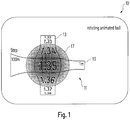
- Fig. 1 shows a schematic diagram of a display 10 for an electronic measurement device according to an embodiment.
- the display 10 is configured to display a graphical user interface 11, and to detect a first and a second user input on the graphical user interface 11.
- the display 10 is further configured to determine a change of a numeric value of the electronic measurement device based on the first user input, and to determine a resolution and/or a value range for the change of the numerical value based on the second user input.
- the display 10 can be a display of the electronic measurement device and can be arranged on the electronic measurement device.
- the display 10 can comprise a display segment embedded in a housing or a frame member, wherein the graphical user interface is displayed in the display segment.
- the display 10 can comprise a touch-sensitive display, wherein the user, for instance, makes an input via a finger or a stylus.
- the user input can be made with a cursor, e.g. a mouse cursor.
- a cursor e.g. a mouse cursor.
- the graphical user interface 11 can comprise a 3D or quasi 3D control element.
- the control element can be a graphical object or a control metaphor.
- the graphical user interface 11 in Fig. 1 comprises an animated ball 17, a first (vertical) scale 13 and a second (horizontal) scale 15 that are wrapped around the ball 17.
- the vertical scale 13 comprises selectable numerical values
- the horizontal scale 15 comprises selectable resolutions of the vertical scale 13.
- a currently selected numerical value is displayed in the center of the ball 17 in Fig. 1 .
- the horizontal scale 15 shows values which are multipliers for the vertical scale 13.
- the values on the horizontal scale 15 can comprise a unit, e.g. meters (m) or Hertz (Hz), which corresponds to the unit of the numerical value of the electronic measurement device.
- Fig. 1 the unit is meters and the selectable orders of magnitudes that are displayed on the horizontal scale 15 are 100 m, 10 m and 1 m, whereas 10 m is currently selected.
- the incrementation of the vertical scale 13 corresponds to the values of the vertical scale 13 multiplied by the selected value of the horizontal scale 15.
- the currently selected value in Fig. 1 is 1,35 x 10 m.
- the first user input can be a vertical swiping movement over the ball 17, and the second user input can be a horizontal swiping movement over the ball 17.
- the ball 17 can be animated to rotate in response to the user inputs.
- the scales 13, 15 can be animated to rotate with the ball 17.
- the graphical user interface 11 can comprise a relatively small graphical object for manipulation, which is easily readable, intuitive to operate, and does not take much space on the display 10 screen.
- Fig. 2a and 2b show schematic diagrams of displays 10 for the electronic measurement device according to further embodiments.
- the graphical user interface 11 comprises selectable numerical values along a first (vertical) axis and selectable resolutions along a second (horizontal) axis.
- the numerical values and selectable ranges are animated as floating objects in a 3-dimensional surrounding.
- a currently selected numerical value floats before a gray background in the center.
- the user can change the resolution of the vertical axis.
- the resolution is represented by decimal places. Currently, two decimal places are selected and the incrementation of the vertical axis is 0,01.
- Fig. 2b the selectable resolution is displayed via a multiplier in the graphical user interface 11, similar to Fig. 1 .
- Fig. 3 shows a schematic diagram of the graphical user interface 11 according to an embodiment.
- the graphical user interface 11 in Fig. 3 comprises two animated 3-dimensional wheels 31, 33, which are wrapped around each other. A currently selected numerical value is displayed at the intersection of both wheels 31, 33.
- a vertical wheel 31 shows a scale of selectable numerical values
- a horizontal wheel 31 shows selectable resolutions of the numerical values. Similar to Fig. 2a , the user can select the decimal places of the values on the vertical wheel 31 via the horizontal wheel 33.
- the user can swipe horizontally over the graphical user interface 11 to select the precision of the numerical values and vertically to select the numerical value.
- the wheels 31, 33 can be animated to rotate in response to the user input.
- Fig. 4 shows a schematic diagram of the graphical user interface 11 according to a further embodiment.
- the graphical user interface 11 in Fig. 4 can be used for selecting frequencies of the electronic measurement device.
- the graphical user interface 11 in Fig. 4 comprises two animated rotary wheels 41, 43, each shwoing a value range.
- the wheels comprise an outer wheel 41 for a course adjustment of the numerical value and an inner wheel 43 for a fine adjustment.
- the outer wheel 41 in Fig. 4 comprises a horn shaped shading and a scale.
- the outer wheel 41 in Fig. 4 comprises a segment marking 45.
- the segment marking 45 can mark a frequency range of the inner wheel 43 and/or can give a rough estimate of the currently selected numerical value.
- the currently selected value can further be displayed in the center of the inner wheel 43.
- the outer wheel in Fig. 4 has a logarithmic scale from 10 mHz to 1 GHz. This allows to course adjust the selected value over a large range.
- the inner wheel 43 can have a linear scale for fine adjustment roughly within the frequency range of the segment marking 43.
- the user input can be a tap or click on the outer wheel 41 and/or a dragging movement over the inner wheel 43.
- the user input on the inner wheel 43 corresponds to the first user input for selecting the value
- the user input on the outer wheel 41 corresponds to the second user input for selecting the value range of the inner wheel 43.
- the display 10 can be configured to store the set numerical value in a list and to display an indicator of the stored numerical value on the value range, e.g. as a mark or arrow on the outer wheel 41.
- the display 10 can comprise a memory or can be connectable to a memory of the electronic measurement device for storing the list.
- Fig. 5a shows a schematic diagram of the graphical user interface 11a, 11b in two different zoom levels according to an embodiment.
- the graphical user interface 11a, 11b in Fig. 5a can correspond to the graphical user interface 11 of Fig. 4 .
- the graphical user interface 11a on the left of Fig. 5a is zoomed out and comprises an animated wheel 41a with a frequency range over six orders of magnitude.
- This graphical user interface 11a can be magnified by a zooming input, e.g. a "pinch to zoom" gesture by two fingers.
- the zooming input corresponds to the second user input.
- the graphical user interface 11b on the right of Fig. 5a corresponds to a magnification of the user interface 11a on the left.
- the animated wheel 41b of the magnified user interface 11b has an increase resolution and a decreased value range over three orders of magnitude, as compared to the zoomed out wheel 41a.
- the resolution and/or value range for selecting the numerical value can be changed.
- Fig. 5b shows a schematic diagram of the graphical user interface 11-1, 11-2, 11-3 in three different zoom levels according to an embodiment.
- the graphical user interface 11-1, 11-2, 11-3 comprises an animated ball 17 and a vertical scale 13 that displays a value range of selectable numerical values. A currently selected numerical value is displayed in the center of the ball 17.
- the resolution of the value range is correlated to the size of the ball. Via a zooming input, the user can increase the size of the ball 17. When the size of the ball reaches a threshold the resolution of the value range is increased by one decimal place. Via vertical swipe gesture over the scale 13, the user can then select a numerical value.
- Fig. 6 shows an electronic measurement device 60 according to an embodiment.
- the electronic measurement device 60 can comprise a display 10, in particular the display 10 as shown in Fig. 1 or Figs. 2a-b .
- the numeric value can define a state and/or a setting of the electronic measuring device 10.
- Changing the numerical value can refer to changing the state or the setting of the electronic measuring device 10 from a first state or setting to a second state or setting.
- Changing the numerical value comprises setting the new numerical value.
- the electronic measurement device 60 can additionally comprise a rotary knob and/or a keyboard to manually change the numerical value.
- the electronic measurement device 60 can be an instrument.
- the electronic measurement device 60 is any one of the following devices: an audio analyzer, an oscilloscope, a network analyzer, a power meter and/or volt meter, a receiver, a meter and/or counter, a signal and/or spectrum analyzer, a test and/or measurement device for broadcasting, a signal generator, a spectrum monitoring device, a wireless communications tester.
- the electronic measurement device 60 can comprise a processing unit and/or a memory that is connectable to the display 10.
- the processing unit can be configured to determine the change of a numeric value of the electronic measurement device 60 based on the first user input and/or to determine the resolution and/or the value range for the change of the numerical value based on the second user input.
- the processing unit can further be configured to adjust a setting or function of the electronic measurement 60 device based on the change of the numeric value.
- the electronic measurement device 60 can further comprise a memory for storing the set respectively changed numerical values in a list.
- Fig. 7 shows a schematic diagram of a method 70 for changing the numeric value of the electronic measurement 60 device according to an embodiment.
- the method 70 comprises the steps of displaying 71 the graphical user interface 11, detecting 73 the first and a second user input on the graphical user interface 11, determining 75 the change of the numeric value of the electronic measurement 60 device based on the first user input, and determining 77 the resolution and/or the value range for the change of the numerical value based on the second user input.
- the resolution and/or value range for changing the numerical value can be displayed in the graphical user interface 11.
- the value range can be a non-linear range, in particular a logarithmic range.
- the method in Fig. 7 comprises the further steps of: storing 78 the set numerical value in a list, and displaying 79 an indicator of the stored numerical value on the value range.
- the currently set numerical value of the electronic measurement 60 device can be displayed on the graphical user interface 11, wherein the number of digits of the displayed numerical value depends on the determined resolution.
- the first and/or the second user input can comprise a swipe and/or a zoom gesture.
- the graphical user interface 11 can comprise a 3D or quasi 3D control element, in particular the ball 17 shown in Fig. 1 or the wheel 31, 33 shown in Fig. 3 .
Landscapes
- Engineering & Computer Science (AREA)
- Theoretical Computer Science (AREA)
- General Engineering & Computer Science (AREA)
- Physics & Mathematics (AREA)
- General Physics & Mathematics (AREA)
- Human Computer Interaction (AREA)
- Computer Hardware Design (AREA)
- Mathematical Physics (AREA)
- User Interface Of Digital Computer (AREA)
Abstract
Description
- The invention relates to a display for an electronic measurement device and an electronic measurement device comprising said display. The invention further relates to a method for changing a numerical value of an electronic measurement device.
- Instruments, such as oscilloscopes or spectrum analyzers, often require inputting specific numerical values, e.g. a specific frequency, to select an instrument setting or function. There are various solutions for inputting such numerical values to the instrument.
- A keyboard, e.g. a touch keyboard on an instrument display, allows directly inputting a numerical value. However, approaching a target value step by step, e.g. to find an optimum value, can be cumbersome with a keyboard, as each new value hast to entered fully.
- A rotary knob allows an incremental or decremental change of a numerical value. However, the increment respectively decrement of a rotary knob is fixed and can be either too coarse or too fine for a certain working range. A possibility to switch between a coarse and a fine setting is not advantageous since it would require additional user inputs.
-
US 2015/0012857 A1 , for instance, discloses a method for operation a virtual adjusting button, which can be a rotary knob. Thereby, a displaying size of the virtual button can be changed in order to change the precision of adjusting a value with the button. However, the precision can only be set indirectly via the size of the adjusting button and the available range of the button cannot be changed as easily. - In contrast to a rotary button, a slider, such as a scrollbar, allows to quickly set a rough approximation of a target value between two limit values. However, such a slider may lack a necessary precision to change a numerical value by a small factor or to set a target value.
-
US 2002/0063737 A1 discloses a graphical user interface method, where a coarse control scrollbar and a magnified view scrollbar with a finer resolution are displayed proximate to each other The magnified view scrollbar can be used for fine adjustment of a value. However, setting a value may require separate inputs on both scrollbars for a course and subsequently a fine adjustment. In addition, the magnification range of the magnified view scrollbar is preset by the user and might be too coarse or too fine for certain situations. -
US 2015/0058801 A1 discloses a system for providing a multi-touch inspection tool for a chart. The inspection tool is displayed on a multi-touch display, wherein a course adjustment of the scaling of the chart can be performed via a multiplier-scale control and a fine adjustment of the scaling can be performed via a separate precision control. However, this system also requires separate inputs on the two control units for a course and subsequently a fine adjustment. - Further, the user cannot change a value range of the controls dynamically.
- Thus, it is an objective to provide an improved display for an electronic measurement device, an improved electronic measurement device and an improved method for changing a numeric value of an electronic measurement device, which avoid the above limitations. In particular, it is an objective to provide a concept for setting and/or changing numerical values of electronic measurement devices that offers a selectable range of settable values and simultaneously provides a high precision for setting respectively changing each value.
- The object of the present invention is achieved by the solution provided in the enclosed independent claims. Advantageous implementations of the present invention are further defined in the dependent claims.
- According to a first aspect, the invention refers to a display for an electronic measurement device, wherein the display is configured to display a graphical user interface, wherein the display is configured to detect a first and a second user input on the graphical user interface, wherein the display is configured to determine a change of a numeric value of the electronic measurement device based on the first user input, and wherein the display is configured to determine a resolution and/or a value range for the change of the numerical value based on the second user input. This achieves the advantage that a numeric value of an electronic measurement device can be changed in a precise and efficient way.
- The display can be arranged on the electronic measurement device.
- The display can comprise a display segment embedded in a housing or a frame member, wherein the graphical user interface is displayed in the display segment.
- The display can comprise a touch-sensitive display, wherein the user, for instance, makes an input via a finger or a stylus.
- Alternatively, the user input can be made with a cursor, e.g. a mouse cursor.
- The numeric value can define a state and/or a setting of the electronic measuring device. Changing the numerical value can refer to changing the state or the setting of the electronic measuring device from an initial state or setting to a new state or setting. Changing the numerical value comprises setting the new numerical value.
- Preferably, the resolution for the change of the numerical value represents an incrementation respectively a decrementation when increasing respectively decreasing the numerical value. The resolution can refer to a precision for changing the numerical value.
- The value range for the change of the numerical value can represent a currently available range from a minimum numerical value to a maximum numerical value within which the numerical value can be changed.
- For instance, if the numerical value is a frequency, e.g. the center frequency of a spectrum, the user can set a maximum value range of 0 to 1 GHz and a maximum resolution of 1 Hz. The user can decrease the resolution to change the frequency quickly over the maximum value range in coarse steps, and/or the user can decrease the value range to set a specific target frequency within the decreased value range with high resolution.
- Preferably, determining the resolution and/or value range can refers to detecting a resolution and/or value range based on the second user input and setting said resolution and/or value range for the first user input.
- The graphical user interface can comprise a scale or a scrollbar. The value range can be a range that is displayed on the scale or scrollbar or that is adjustable via the scale or scrollbar. The resolution can refer to a resolution of the scale or scrollbar, in particular an incrementation of the scale or scrollbar.
- The display can comprise a processing unit or can be connectable to a processing unit of the electronic measurement device.
- The processing unit can be configured to determine the change of a numeric value of the electronic measurement device based on the first user input and/or to determine the resolution and/or the value range for the change of the numerical value based on the second user input.
- The processing unit can further be configured to adjust a setting or function of the electronic measurement device based on the change of the numeric value.
- In an embodiment, the display is configured to display the resolution and/or value range for changing the numerical value in the graphical user interface. This achieves the advantage that the numerical value can be changed efficiently with a known resolution and/or within a known value range.
- Preferably, the display is configured to display further selectable resolutions and/or value ranges besides the determined resolution and/or value range.
- In an embodiment, after changing the numerical value, the display is configured to store the set numerical value in a list. This achieves the advantage that the electronic measurement device can be reset to a previously set numerical value.
- The display can comprise a memory or can be connectable to a memory of the electronic measurement device for storing the list.
- In an embodiment, the display is configured to display an indicator of the stored numerical value on the value range. This achieves the advantage that the electronic measurement device can be reset to a previously set numerical value.
- The indicator can be an arrow or a marker on a scale or scrollbar.
- In an embodiment, the value range is a non-linear range, in particular a logarithmic range. This provides the advantage, that the numerical value can be changed over a large value range.
- In an embodiment, the display is configured to display a currently set numerical value of the electronic measurement device, wherein a number of digits of the displayed numerical value depends on the determined resolution. This achieves the advantage that a current setting of the electronic measurement device is displayed efficiently.
- In an embodiment, the first and/or the second user input comprise a swipe and/or a zoom gesture. This achieve the advantage that the user input can be made efficiently.
- In an embodiment, the graphical user interface comprises a 3D or quasi 3D control element, in particular a ball or a wheel.
- In an embodiment, the graphical user interface comprises a first scale of selectable numerical values along a first axis, and a second scale of selectable resolutions for the first scale. This achieves the advantage that the graphical user interface can be used for coarse and fine adjustment of the numerical value.
- Preferably, the first axis and the second axis are perpendicular. The first axis can be a horizontal axis and the second axis can be a vertical axis, or vice versa.
- A currently set numerical value can be displayed in an intersection of the first and the second axis.
- According to a second aspect, the invention relates to an electronic measurement device, comprising the display of the first aspect of the invention. This achieves the advantage that a numeric value of an electronic measurement device can be changed in a precise and efficient way.
- The numeric value can define a state and/or a setting of the electronic measuring device.
- In an embodiment, the electronic measurement device is any one of the following devices: an audio analyzer, an oscilloscope, a network analyzer, a power meter and/or volt meter, a receiver, a meter and/or counter, a signal and/or spectrum analyzer, a test and/or measurement device for broadcasting, a signal generator, a spectrum monitoring device, a wireless communications tester.
- According to a third aspect, the invention relates to a method for changing a numerical value of an electronic measurement device, comprising the steps of: displaying a graphical user interface, detecting a first and a second user input on the graphical user interface, determining a change of a numeric value of the electronic measurement device based on the first user input, and determining a resolution and/or a value range for the change of the numerical value based on the second user input. This achieves the advantage that a numeric value of an electronic measurement device can be changed in a precise and efficient way.
- In an embodiment, the determined resolution and/or value range for changing the numerical value is displayed in the graphical user interface. This achieves the advantage that the value can be changed efficiently with a known resolution and/or within a known value range.
- In an embodiment, the method comprises the further steps of: after changing the numerical value, storing the set numerical value in a list, and displaying an indicator of the stored numerical value on the value range. This achieves the advantage that the electronic measurement device can be reset to a previously set numerical value.
- In an embodiment, the value range is a non-linear range, in particular a logarithmic range. This provides the advantage, that the numerical value can be changed over a large value range.
- In an embodiment, a currently set numerical value of the electronic measurement device is displayed in the graphical user interface, wherein a number of digits of the displayed numerical value depends on the determined resolution. This achieves the advantage that a current setting of the electronic measurement device is displayed efficiently.
- In an embodiment, the first and/or the second user input comprise a swipe and/or a zoom gesture. This achieve the advantage that the user input can be made efficiently.
- In an embodiment, the graphical user interface comprises a 3D or quasi 3D control element, in particular a ball or a wheel.
- A computer program product can comprise program code for performing the steps of the above described method, when the computer program product runs on a computer or a digital signal processor.
- The invention will be explained in the followings together with the figures.
- Fig. 1
- shows a schematic diagram of a display for an electronic measurement device according to an embodiment;
- Fig. 2a-b
- show schematic diagrams of displays for an electronic measurement device according to an embodiment;
- Fig. 3
- shows a schematic diagram of a graphical user interface according to an embodiment;
- Fig. 4
- shows a schematic diagram of a graphical user interface according to an embodiment;
- Fig. 5a
- shows a schematic diagram of a graphical user interface in two different zoom levels according to an embodiment;
- Fig. 5b
- shows a schematic diagram of a graphical user interface in three different zoom levels according to an embodiment;
- Fig. 6
- shows a schematic diagram of an electronic measurement device according to an embodiment; and
- Fig. 7
- shows a schematic diagram of a method for changing a numeric value of an electronic measurement device according to an embodiment.
-
Fig. 1 shows a schematic diagram of adisplay 10 for an electronic measurement device according to an embodiment. - The
display 10 is configured to display agraphical user interface 11, and to detect a first and a second user input on thegraphical user interface 11. Thedisplay 10 is further configured to determine a change of a numeric value of the electronic measurement device based on the first user input, and to determine a resolution and/or a value range for the change of the numerical value based on the second user input. - The
display 10 can be a display of the electronic measurement device and can be arranged on the electronic measurement device. - The
display 10 can comprise a display segment embedded in a housing or a frame member, wherein the graphical user interface is displayed in the display segment. - The
display 10 can comprise a touch-sensitive display, wherein the user, for instance, makes an input via a finger or a stylus. - Alternatively, the user input can be made with a cursor, e.g. a mouse cursor.
- The
graphical user interface 11 can comprise a 3D or quasi 3D control element. The control element can be a graphical object or a control metaphor. - The
graphical user interface 11 inFig. 1 comprises ananimated ball 17, a first (vertical)scale 13 and a second (horizontal)scale 15 that are wrapped around theball 17. - In
Fig. 1 , thevertical scale 13 comprises selectable numerical values, while thehorizontal scale 15 comprises selectable resolutions of thevertical scale 13. A currently selected numerical value is displayed in the center of theball 17 inFig. 1 . - In particular, the
horizontal scale 15 shows values which are multipliers for thevertical scale 13. The values on thehorizontal scale 15 can comprise a unit, e.g. meters (m) or Hertz (Hz), which corresponds to the unit of the numerical value of the electronic measurement device. - In
Fig. 1 the unit is meters and the selectable orders of magnitudes that are displayed on thehorizontal scale 15 are 100 m, 10 m and 1 m, whereas 10 m is currently selected. The incrementation of thevertical scale 13 corresponds to the values of thevertical scale 13 multiplied by the selected value of thehorizontal scale 15. The currently selected value inFig. 1 is 1,35 x 10 m. - The first user input can be a vertical swiping movement over the
ball 17, and the second user input can be a horizontal swiping movement over theball 17. Theball 17 can be animated to rotate in response to the user inputs. Thescales ball 17. - Thus, the
graphical user interface 11 can comprise a relatively small graphical object for manipulation, which is easily readable, intuitive to operate, and does not take much space on thedisplay 10 screen. -
Fig. 2a and 2b show schematic diagrams ofdisplays 10 for the electronic measurement device according to further embodiments. - In
Fig. 2a thegraphical user interface 11 comprises selectable numerical values along a first (vertical) axis and selectable resolutions along a second (horizontal) axis. The numerical values and selectable ranges are animated as floating objects in a 3-dimensional surrounding. A currently selected numerical value floats before a gray background in the center. - By horizontally swiping over the display, the user can change the resolution of the vertical axis. In
Fig. 2a , the resolution is represented by decimal places. Currently, two decimal places are selected and the incrementation of the vertical axis is 0,01. - In
Fig. 2b the selectable resolution is displayed via a multiplier in thegraphical user interface 11, similar toFig. 1 . -
Fig. 3 shows a schematic diagram of thegraphical user interface 11 according to an embodiment. - The
graphical user interface 11 inFig. 3 comprises two animated 3-dimensional wheels wheels - In
Fig. 3 , avertical wheel 31 shows a scale of selectable numerical values, while ahorizontal wheel 31 shows selectable resolutions of the numerical values. Similar toFig. 2a , the user can select the decimal places of the values on thevertical wheel 31 via thehorizontal wheel 33. - The user can swipe horizontally over the
graphical user interface 11 to select the precision of the numerical values and vertically to select the numerical value. Thewheels -
Fig. 4 shows a schematic diagram of thegraphical user interface 11 according to a further embodiment. Thegraphical user interface 11 inFig. 4 can be used for selecting frequencies of the electronic measurement device. - The
graphical user interface 11 inFig. 4 comprises twoanimated rotary wheels outer wheel 41 for a course adjustment of the numerical value and aninner wheel 43 for a fine adjustment. Theouter wheel 41 inFig. 4 comprises a horn shaped shading and a scale. - The
outer wheel 41 inFig. 4 comprises a segment marking 45. The segment marking 45 can mark a frequency range of theinner wheel 43 and/or can give a rough estimate of the currently selected numerical value. The currently selected value can further be displayed in the center of theinner wheel 43. - The outer wheel in
Fig. 4 has a logarithmic scale from 10 mHz to 1 GHz. This allows to course adjust the selected value over a large range. Theinner wheel 43 can have a linear scale for fine adjustment roughly within the frequency range of the segment marking 43. - The user input can be a tap or click on the
outer wheel 41 and/or a dragging movement over theinner wheel 43. In particular, the user input on theinner wheel 43 corresponds to the first user input for selecting the value, and the user input on theouter wheel 41 corresponds to the second user input for selecting the value range of theinner wheel 43. - The
display 10 can be configured to store the set numerical value in a list and to display an indicator of the stored numerical value on the value range, e.g. as a mark or arrow on theouter wheel 41. - The
display 10 can comprise a memory or can be connectable to a memory of the electronic measurement device for storing the list. -
Fig. 5a shows a schematic diagram of thegraphical user interface graphical user interface Fig. 5a can correspond to thegraphical user interface 11 ofFig. 4 . - The
graphical user interface 11a on the left ofFig. 5a is zoomed out and comprises an animated wheel 41a with a frequency range over six orders of magnitude. Thisgraphical user interface 11a can be magnified by a zooming input, e.g. a "pinch to zoom" gesture by two fingers. In particular, the zooming input corresponds to the second user input. - The
graphical user interface 11b on the right ofFig. 5a corresponds to a magnification of theuser interface 11a on the left. The animated wheel 41b of the magnifieduser interface 11b has an increase resolution and a decreased value range over three orders of magnitude, as compared to the zoomed out wheel 41a. - Thus, by changing the magnification of the
graphical user interface -
Fig. 5b shows a schematic diagram of the graphical user interface 11-1, 11-2, 11-3 in three different zoom levels according to an embodiment. - The graphical user interface 11-1, 11-2, 11-3 comprises an
animated ball 17 and avertical scale 13 that displays a value range of selectable numerical values. A currently selected numerical value is displayed in the center of theball 17. - The resolution of the value range is correlated to the size of the ball. Via a zooming input, the user can increase the size of the
ball 17. When the size of the ball reaches a threshold the resolution of the value range is increased by one decimal place. Via vertical swipe gesture over thescale 13, the user can then select a numerical value. -
Fig. 6 shows anelectronic measurement device 60 according to an embodiment. - The
electronic measurement device 60 can comprise adisplay 10, in particular thedisplay 10 as shown inFig. 1 orFigs. 2a-b . - The numeric value can define a state and/or a setting of the
electronic measuring device 10. Changing the numerical value can refer to changing the state or the setting of theelectronic measuring device 10 from a first state or setting to a second state or setting. Changing the numerical value comprises setting the new numerical value. - The
electronic measurement device 60 can additionally comprise a rotary knob and/or a keyboard to manually change the numerical value. - The
electronic measurement device 60 can be an instrument. In particular, theelectronic measurement device 60 is any one of the following devices: an audio analyzer, an oscilloscope, a network analyzer, a power meter and/or volt meter, a receiver, a meter and/or counter, a signal and/or spectrum analyzer, a test and/or measurement device for broadcasting, a signal generator, a spectrum monitoring device, a wireless communications tester. - The
electronic measurement device 60 can comprise a processing unit and/or a memory that is connectable to thedisplay 10. - The processing unit can be configured to determine the change of a numeric value of the
electronic measurement device 60 based on the first user input and/or to determine the resolution and/or the value range for the change of the numerical value based on the second user input. - The processing unit can further be configured to adjust a setting or function of the
electronic measurement 60 device based on the change of the numeric value. - The
electronic measurement device 60 can further comprise a memory for storing the set respectively changed numerical values in a list. -
Fig. 7 shows a schematic diagram of amethod 70 for changing the numeric value of theelectronic measurement 60 device according to an embodiment. - The
method 70 comprises the steps of displaying 71 thegraphical user interface 11, detecting 73 the first and a second user input on thegraphical user interface 11, determining 75 the change of the numeric value of theelectronic measurement 60 device based on the first user input, and determining 77 the resolution and/or the value range for the change of the numerical value based on the second user input. - The resolution and/or value range for changing the numerical value can be displayed in the
graphical user interface 11. - The value range can be a non-linear range, in particular a logarithmic range.
- The method in
Fig. 7 comprises the further steps of: storing 78 the set numerical value in a list, and displaying 79 an indicator of the stored numerical value on the value range. - The currently set numerical value of the
electronic measurement 60 device can be displayed on thegraphical user interface 11, wherein the number of digits of the displayed numerical value depends on the determined resolution. - The first and/or the second user input can comprise a swipe and/or a zoom gesture.
- The
graphical user interface 11 can comprise a 3D or quasi 3D control element, in particular theball 17 shown inFig. 1 or thewheel Fig. 3 . - It is important to note that the
display 10, theelectronic measurement device 60 and themethod 70 very closely correspond. Therefore, all of the above said regarding thedisplay 10 is also applicable to theelectronic measurement device 60 and themethod 70. Everything which is described in the description and/or claimed in the claims and/or drawn in the drawings can be combined. - All features described above or features shown in the figures can be combined with each other in any advantageous manner within the scope of the invention.
Claims (18)
- A display (10) for an electronic measurement device (60),
wherein the display (10) is configured to display a graphical user interface (11),
wherein the display (10) is configured to detect a first and a second user input on the graphical user interface (11),
wherein the display (10) is configured to determine a change of a numeric value of the electronic measurement device (60) based on the first user input, and
wherein the display (10) is configured to determine a resolution and/or a value range for the change of the numerical value based on the second user input. - The display (10) of claim 1, wherein the display (10) is configured to display the resolution and/or value range for changing the numerical value in the graphical user interface (11) .
- The display (10) of claim 1 or 2, wherein, after changing the numerical value, the display (10) is configured to store the set numerical value in a list.
- The display (10) of claim 2 and 3, wherein the display (10) is configured to display an indicator of the stored numerical value on the value range.
- The display (10) of any one of the preceding claims, wherein the value range is a non-linear range, in particular a logarithmic range.
- The display (10) of any one of the preceding claims, wherein the display (10) is configured to display a currently set numerical value of the electronic measurement device (60), wherein a number of digits of the displayed numerical value depends on the determined resolution.
- The display (10) of any one of the preceding claims, wherein the first and/or the second user input comprise a swipe and/or a zoom gesture.
- The display (10) of any one of the preceding claims, wherein the graphical user interface (11) comprises a 3D or quasi 3D control element, in particular a ball (17) or a wheel (31, 33).
- The display (10) of any one of the preceding claims, wherein the graphical user interface (11) comprises a first scale (13) of selectable numerical values along a first axis, and a second scale (15) of selectable resolutions for the first scale (13).
- An electronic measurement device (60) comprising the display (10) of any one of the preceding claims.
- The electronic measurement device (60) of claim 10, wherein the electronic measurement device (60) is any one of the following devices: an audio analyzer, an oscilloscope, a network analyzer, a power meter and/or volt meter, a receiver, a meter and/or counter, a signal and/or spectrum analyzer, a test and/or measurement device for broadcasting, a signal generator, a spectrum monitoring device, a wireless communications tester.
- A method (70) for changing a numerical value of an electronic measurement device (60), comprising the steps of:displaying (71) a graphical user interface (11),detecting (73) a first and a second user input on the graphical user interface (11),determining (75) a change of a numeric value of the electronic measurement device (60) based on the first user input, anddetermining (77) a resolution and/or a value range for the change of the numerical value based on the second user input.
- The method (70) of claim 12, wherein the resolution and/or value range for changing the numerical value is displayed in the graphical user interface (11).
- The method (70) of claim 13, comprising the further steps of:after changing the numerical value, storing (78) the set numerical value in a list, anddisplaying (79) an indicator of the stored numerical value on the value range.
- The method (70) of any one of claims 12 to 14, wherein the value range is a non-linear range, in particular a logarithmic range.
- The method (70) of any one of claims 12 to 15, wherein a currently set numerical value of the electronic measurement device (60) is displayed in the graphical user interface (11), wherein a number of digits of the displayed numerical value depends on the determined resolution.
- The method (70) of any one of claims 12 to 16, wherein the first and/or the second user input comprise a swipe and/or a zoom gesture.
- The method (70) of any one of claims 12 to 17, wherein the graphical user interface (11) comprises a 3D or quasi 3D control element, in particular a ball (17) or a wheel (31, 33) .
Priority Applications (3)
| Application Number | Priority Date | Filing Date | Title |
|---|---|---|---|
| EP19209358.1A EP3822760B8 (en) | 2019-11-15 | 2019-11-15 | Display for an electronic measurement device and method to change a numerical value of an electronic measurement device |
| US16/876,827 US11402983B2 (en) | 2019-11-15 | 2020-05-18 | Display for an electronic measurement device and method to change a numerical value of an electronic measurement device |
| CN202010435465.5A CN112817509B (en) | 2019-11-15 | 2020-05-21 | Display of electronic measuring device and method for changing the value of electronic measuring device |
Applications Claiming Priority (1)
| Application Number | Priority Date | Filing Date | Title |
|---|---|---|---|
| EP19209358.1A EP3822760B8 (en) | 2019-11-15 | 2019-11-15 | Display for an electronic measurement device and method to change a numerical value of an electronic measurement device |
Publications (3)
| Publication Number | Publication Date |
|---|---|
| EP3822760A1 true EP3822760A1 (en) | 2021-05-19 |
| EP3822760B1 EP3822760B1 (en) | 2023-03-01 |
| EP3822760B8 EP3822760B8 (en) | 2023-03-22 |
Family
ID=68583137
Family Applications (1)
| Application Number | Title | Priority Date | Filing Date |
|---|---|---|---|
| EP19209358.1A Active EP3822760B8 (en) | 2019-11-15 | 2019-11-15 | Display for an electronic measurement device and method to change a numerical value of an electronic measurement device |
Country Status (3)
| Country | Link |
|---|---|
| US (1) | US11402983B2 (en) |
| EP (1) | EP3822760B8 (en) |
| CN (1) | CN112817509B (en) |
Cited By (1)
| Publication number | Priority date | Publication date | Assignee | Title |
|---|---|---|---|---|
| US20230379067A1 (en) * | 2022-05-18 | 2023-11-23 | Rohde & Schwarz Gmbh & Co. Kg | Augmented reality spectrum monitoring system |
Families Citing this family (3)
| Publication number | Priority date | Publication date | Assignee | Title |
|---|---|---|---|---|
| US11599258B2 (en) * | 2021-02-18 | 2023-03-07 | The Toronto-Dominion Bank | User interface for smartwatches and wearable devices |
| CN115599278A (en) * | 2022-11-25 | 2023-01-13 | 三亚海兰寰宇海洋信息科技有限公司(Cn) | A method, device and equipment for setting a speed threshold of a target object |
| EP4703747A1 (en) * | 2024-08-28 | 2026-03-04 | Rohde & Schwarz GmbH & Co. KG | Method for controlling a test and/or measurement system |
Citations (6)
| Publication number | Priority date | Publication date | Assignee | Title |
|---|---|---|---|---|
| US5289205A (en) * | 1991-11-20 | 1994-02-22 | International Business Machines Corporation | Method and apparatus of enhancing presentation of data for selection as inputs to a process in a data processing system |
| GB2307383A (en) * | 1995-11-13 | 1997-05-21 | Ibm | Improving resolution of graphical user interface-specified values in a computersystem |
| US20020063737A1 (en) | 2000-11-30 | 2002-05-30 | Ephraim Feig | Zoom-capable scrollbar |
| US20030117380A1 (en) * | 1999-03-16 | 2003-06-26 | International Business Machines Corporation | Method of inputting a numerical value using a touch panel and input apparatus thereof |
| US20150012857A1 (en) | 2013-07-08 | 2015-01-08 | Wistron Corporation | Method for operating virtual adjusting button |
| US20150058801A1 (en) | 2013-08-23 | 2015-02-26 | General Electric Company | Multi-touch inspection tool |
Family Cites Families (13)
| Publication number | Priority date | Publication date | Assignee | Title |
|---|---|---|---|---|
| EP1804154A3 (en) * | 2005-12-27 | 2012-08-08 | Poston Timothy | Computer input device enabling three degrees of freedom and related input and feedback methods |
| US8610673B2 (en) * | 2008-12-03 | 2013-12-17 | Microsoft Corporation | Manipulation of list on a multi-touch display |
| US8970448B2 (en) * | 2009-06-18 | 2015-03-03 | Hiperwall, Inc. | Systems, methods, and devices for manipulation of images on tiled displays |
| CN201575822U (en) * | 2009-12-24 | 2010-09-08 | 卢东方 | Intelligent digital display instrument set by knob |
| US8875054B2 (en) * | 2010-07-30 | 2014-10-28 | Apple Inc. | Hybrid knob/slider control |
| US20140229884A1 (en) * | 2011-09-07 | 2014-08-14 | Nec Casio Mobile Communications, Ltd. | Terminal device, information input method, and program |
| DE102011084802A1 (en) * | 2011-10-19 | 2013-04-25 | Siemens Aktiengesellschaft | Display and operating device |
| US9849361B2 (en) * | 2014-05-14 | 2017-12-26 | Adidas Ag | Sports ball athletic activity monitoring methods and systems |
| CN111035394B (en) * | 2014-09-02 | 2023-06-30 | 苹果公司 | Physical activity and fitness monitor |
| JP2016075808A (en) * | 2014-10-07 | 2016-05-12 | ヤマハ株式会社 | Parameter value setting device |
| EP3012729B1 (en) * | 2014-10-24 | 2023-06-07 | Electrolux Appliances Aktiebolag | Graphical user interface |
| JP6892783B2 (en) * | 2017-04-19 | 2021-06-23 | 株式会社清水合金製作所 | Rotary valve with minute opening display function and minute opening adjustment method |
| CN110426545B (en) * | 2019-09-27 | 2019-12-24 | 深圳市鼎阳科技有限公司 | Precision adjusting method based on digital compensation and digital oscilloscope |
-
2019
- 2019-11-15 EP EP19209358.1A patent/EP3822760B8/en active Active
-
2020
- 2020-05-18 US US16/876,827 patent/US11402983B2/en active Active
- 2020-05-21 CN CN202010435465.5A patent/CN112817509B/en active Active
Patent Citations (6)
| Publication number | Priority date | Publication date | Assignee | Title |
|---|---|---|---|---|
| US5289205A (en) * | 1991-11-20 | 1994-02-22 | International Business Machines Corporation | Method and apparatus of enhancing presentation of data for selection as inputs to a process in a data processing system |
| GB2307383A (en) * | 1995-11-13 | 1997-05-21 | Ibm | Improving resolution of graphical user interface-specified values in a computersystem |
| US20030117380A1 (en) * | 1999-03-16 | 2003-06-26 | International Business Machines Corporation | Method of inputting a numerical value using a touch panel and input apparatus thereof |
| US20020063737A1 (en) | 2000-11-30 | 2002-05-30 | Ephraim Feig | Zoom-capable scrollbar |
| US20150012857A1 (en) | 2013-07-08 | 2015-01-08 | Wistron Corporation | Method for operating virtual adjusting button |
| US20150058801A1 (en) | 2013-08-23 | 2015-02-26 | General Electric Company | Multi-touch inspection tool |
Cited By (2)
| Publication number | Priority date | Publication date | Assignee | Title |
|---|---|---|---|---|
| US20230379067A1 (en) * | 2022-05-18 | 2023-11-23 | Rohde & Schwarz Gmbh & Co. Kg | Augmented reality spectrum monitoring system |
| US12155421B2 (en) * | 2022-05-18 | 2024-11-26 | Rohde & Schwarz Gmbh & Co. Kg | Augmented reality spectrum monitoring system |
Also Published As
| Publication number | Publication date |
|---|---|
| CN112817509A (en) | 2021-05-18 |
| US20210149550A1 (en) | 2021-05-20 |
| US11402983B2 (en) | 2022-08-02 |
| EP3822760B8 (en) | 2023-03-22 |
| CN112817509B (en) | 2024-07-12 |
| EP3822760B1 (en) | 2023-03-01 |
Similar Documents
| Publication | Publication Date | Title |
|---|---|---|
| US11402983B2 (en) | Display for an electronic measurement device and method to change a numerical value of an electronic measurement device | |
| US8217906B2 (en) | User interface, apparatus, method, and computer program for viewing of content on a screen | |
| US8928615B2 (en) | Oscilloscope with touch control and touch control operating method of displaying waveform thereof | |
| TWI567631B (en) | Method for operating virtual adjusting button | |
| US10180781B2 (en) | Non-linear slider systems and methods | |
| EP2827332B1 (en) | Navigating within a media item | |
| US8907910B2 (en) | Context based gesture-controlled instrument interface | |
| CN103959362A (en) | Magnifying tool for viewing and interacting with data visualizations on mobile devices | |
| EP1950652A1 (en) | Method and apparatus for choosing ranges from a multi-range slider | |
| KR101885132B1 (en) | Apparatus and method for input by touch in user equipment | |
| WO2014166518A1 (en) | Multitouch gestures for a measurement system | |
| CN102414634B (en) | Supervisory control system and method | |
| EP2757454B1 (en) | Information displaying device, method, and program | |
| WO2021001385A1 (en) | Method for adapting sensitivity of a pointing device, computer program and image evaluation device | |
| GB2465028A (en) | Using graphical sliders to control portions of a parameter in a user interface | |
| EP3822761B1 (en) | Display for an electronic measurement device | |
| US20210405863A1 (en) | Measurement device and method for operating a measurement device | |
| US10114538B2 (en) | Apparatus, measurement equipment and method for displaying images | |
| JP3120510U (en) | Data display device for measuring equipment | |
| JP2017174363A (en) | Setting device and method | |
| US11609690B2 (en) | Method for manually adjusting a numerical value displayed on a touch screen, and measurement device | |
| Hayes et al. | Modelling touch-interaction time on smartphones | |
| CN114764287A (en) | Measurement data analysis device, measurement device, and data analysis method | |
| WO2024180795A1 (en) | Information processing device, information processing method, and information processing program | |
| CN121633581A (en) | Methods for controlling test and/or measurement systems |
Legal Events
| Date | Code | Title | Description |
|---|---|---|---|
| PUAI | Public reference made under article 153(3) epc to a published international application that has entered the european phase |
Free format text: ORIGINAL CODE: 0009012 |
|
| STAA | Information on the status of an ep patent application or granted ep patent |
Free format text: STATUS: REQUEST FOR EXAMINATION WAS MADE |
|
| STAA | Information on the status of an ep patent application or granted ep patent |
Free format text: STATUS: EXAMINATION IS IN PROGRESS |
|
| 17P | Request for examination filed |
Effective date: 20200813 |
|
| AK | Designated contracting states |
Kind code of ref document: A1 Designated state(s): AL AT BE BG CH CY CZ DE DK EE ES FI FR GB GR HR HU IE IS IT LI LT LU LV MC MK MT NL NO PL PT RO RS SE SI SK SM TR |
|
| 17Q | First examination report despatched |
Effective date: 20210512 |
|
| REG | Reference to a national code |
Ref country code: DE Ref legal event code: R079 Ref document number: 602019025780 Country of ref document: DE Free format text: PREVIOUS MAIN CLASS: G06F0003048400 Ipc: G06F0003048470 |
|
| RIC1 | Information provided on ipc code assigned before grant |
Ipc: G06F 3/04847 20220101AFI20221013BHEP |
|
| GRAP | Despatch of communication of intention to grant a patent |
Free format text: ORIGINAL CODE: EPIDOSNIGR1 |
|
| STAA | Information on the status of an ep patent application or granted ep patent |
Free format text: STATUS: GRANT OF PATENT IS INTENDED |
|
| GRAS | Grant fee paid |
Free format text: ORIGINAL CODE: EPIDOSNIGR3 |
|
| INTG | Intention to grant announced |
Effective date: 20221125 |
|
| GRAA | (expected) grant |
Free format text: ORIGINAL CODE: 0009210 |
|
| STAA | Information on the status of an ep patent application or granted ep patent |
Free format text: STATUS: THE PATENT HAS BEEN GRANTED |
|
| AK | Designated contracting states |
Kind code of ref document: B1 Designated state(s): AL AT BE BG CH CY CZ DE DK EE ES FI FR GB GR HR HU IE IS IT LI LT LU LV MC MK MT NL NO PL PT RO RS SE SI SK SM TR |
|
| REG | Reference to a national code |
Ref country code: GB Ref legal event code: FG4D |
|
| REG | Reference to a national code |
Ref country code: CH Ref legal event code: PL Ref country code: CH Ref legal event code: PK Free format text: BERICHTIGUNG B8 Ref country code: CH Ref legal event code: EP Ref country code: AT Ref legal event code: REF Ref document number: 1551453 Country of ref document: AT Kind code of ref document: T Effective date: 20230315 |
|
| RBV | Designated contracting states (corrected) |
Designated state(s): AL AT BE BG CY CZ DE DK EE ES FI FR GB GR HR HU IS IT LT LU LV MC MK MT NL NO PL PT RO RS SE SI SK SM TR |
|
| REG | Reference to a national code |
Ref country code: DE Ref legal event code: R096 Ref document number: 602019025780 Country of ref document: DE |
|
| REG | Reference to a national code |
Ref country code: IE Ref legal event code: FG4D |
|
| REG | Reference to a national code |
Ref country code: LT Ref legal event code: MG9D |
|
| P01 | Opt-out of the competence of the unified patent court (upc) registered |
Effective date: 20230525 |
|
| REG | Reference to a national code |
Ref country code: NL Ref legal event code: MP Effective date: 20230301 |
|
| PG25 | Lapsed in a contracting state [announced via postgrant information from national office to epo] |
Ref country code: RS Free format text: LAPSE BECAUSE OF FAILURE TO SUBMIT A TRANSLATION OF THE DESCRIPTION OR TO PAY THE FEE WITHIN THE PRESCRIBED TIME-LIMIT Effective date: 20230301 Ref country code: NO Free format text: LAPSE BECAUSE OF FAILURE TO SUBMIT A TRANSLATION OF THE DESCRIPTION OR TO PAY THE FEE WITHIN THE PRESCRIBED TIME-LIMIT Effective date: 20230601 Ref country code: LV Free format text: LAPSE BECAUSE OF FAILURE TO SUBMIT A TRANSLATION OF THE DESCRIPTION OR TO PAY THE FEE WITHIN THE PRESCRIBED TIME-LIMIT Effective date: 20230301 Ref country code: LT Free format text: LAPSE BECAUSE OF FAILURE TO SUBMIT A TRANSLATION OF THE DESCRIPTION OR TO PAY THE FEE WITHIN THE PRESCRIBED TIME-LIMIT Effective date: 20230301 Ref country code: HR Free format text: LAPSE BECAUSE OF FAILURE TO SUBMIT A TRANSLATION OF THE DESCRIPTION OR TO PAY THE FEE WITHIN THE PRESCRIBED TIME-LIMIT Effective date: 20230301 Ref country code: ES Free format text: LAPSE BECAUSE OF FAILURE TO SUBMIT A TRANSLATION OF THE DESCRIPTION OR TO PAY THE FEE WITHIN THE PRESCRIBED TIME-LIMIT Effective date: 20230301 |
|
| REG | Reference to a national code |
Ref country code: AT Ref legal event code: MK05 Ref document number: 1551453 Country of ref document: AT Kind code of ref document: T Effective date: 20230301 |
|
| PG25 | Lapsed in a contracting state [announced via postgrant information from national office to epo] |
Ref country code: SE Free format text: LAPSE BECAUSE OF FAILURE TO SUBMIT A TRANSLATION OF THE DESCRIPTION OR TO PAY THE FEE WITHIN THE PRESCRIBED TIME-LIMIT Effective date: 20230301 Ref country code: PL Free format text: LAPSE BECAUSE OF FAILURE TO SUBMIT A TRANSLATION OF THE DESCRIPTION OR TO PAY THE FEE WITHIN THE PRESCRIBED TIME-LIMIT Effective date: 20230301 Ref country code: NL Free format text: LAPSE BECAUSE OF FAILURE TO SUBMIT A TRANSLATION OF THE DESCRIPTION OR TO PAY THE FEE WITHIN THE PRESCRIBED TIME-LIMIT Effective date: 20230301 Ref country code: GR Free format text: LAPSE BECAUSE OF FAILURE TO SUBMIT A TRANSLATION OF THE DESCRIPTION OR TO PAY THE FEE WITHIN THE PRESCRIBED TIME-LIMIT Effective date: 20230602 Ref country code: FI Free format text: LAPSE BECAUSE OF FAILURE TO SUBMIT A TRANSLATION OF THE DESCRIPTION OR TO PAY THE FEE WITHIN THE PRESCRIBED TIME-LIMIT Effective date: 20230301 |
|
| PG25 | Lapsed in a contracting state [announced via postgrant information from national office to epo] |
Ref country code: SM Free format text: LAPSE BECAUSE OF FAILURE TO SUBMIT A TRANSLATION OF THE DESCRIPTION OR TO PAY THE FEE WITHIN THE PRESCRIBED TIME-LIMIT Effective date: 20230301 Ref country code: RO Free format text: LAPSE BECAUSE OF FAILURE TO SUBMIT A TRANSLATION OF THE DESCRIPTION OR TO PAY THE FEE WITHIN THE PRESCRIBED TIME-LIMIT Effective date: 20230301 Ref country code: PT Free format text: LAPSE BECAUSE OF FAILURE TO SUBMIT A TRANSLATION OF THE DESCRIPTION OR TO PAY THE FEE WITHIN THE PRESCRIBED TIME-LIMIT Effective date: 20230703 Ref country code: EE Free format text: LAPSE BECAUSE OF FAILURE TO SUBMIT A TRANSLATION OF THE DESCRIPTION OR TO PAY THE FEE WITHIN THE PRESCRIBED TIME-LIMIT Effective date: 20230301 Ref country code: CZ Free format text: LAPSE BECAUSE OF FAILURE TO SUBMIT A TRANSLATION OF THE DESCRIPTION OR TO PAY THE FEE WITHIN THE PRESCRIBED TIME-LIMIT Effective date: 20230301 Ref country code: AT Free format text: LAPSE BECAUSE OF FAILURE TO SUBMIT A TRANSLATION OF THE DESCRIPTION OR TO PAY THE FEE WITHIN THE PRESCRIBED TIME-LIMIT Effective date: 20230301 |
|
| PG25 | Lapsed in a contracting state [announced via postgrant information from national office to epo] |
Ref country code: SK Free format text: LAPSE BECAUSE OF FAILURE TO SUBMIT A TRANSLATION OF THE DESCRIPTION OR TO PAY THE FEE WITHIN THE PRESCRIBED TIME-LIMIT Effective date: 20230301 Ref country code: IS Free format text: LAPSE BECAUSE OF FAILURE TO SUBMIT A TRANSLATION OF THE DESCRIPTION OR TO PAY THE FEE WITHIN THE PRESCRIBED TIME-LIMIT Effective date: 20230701 |
|
| REG | Reference to a national code |
Ref country code: DE Ref legal event code: R097 Ref document number: 602019025780 Country of ref document: DE |
|
| PLBE | No opposition filed within time limit |
Free format text: ORIGINAL CODE: 0009261 |
|
| STAA | Information on the status of an ep patent application or granted ep patent |
Free format text: STATUS: NO OPPOSITION FILED WITHIN TIME LIMIT |
|
| PG25 | Lapsed in a contracting state [announced via postgrant information from national office to epo] |
Ref country code: SI Free format text: LAPSE BECAUSE OF FAILURE TO SUBMIT A TRANSLATION OF THE DESCRIPTION OR TO PAY THE FEE WITHIN THE PRESCRIBED TIME-LIMIT Effective date: 20230301 Ref country code: DK Free format text: LAPSE BECAUSE OF FAILURE TO SUBMIT A TRANSLATION OF THE DESCRIPTION OR TO PAY THE FEE WITHIN THE PRESCRIBED TIME-LIMIT Effective date: 20230301 |
|
| 26N | No opposition filed |
Effective date: 20231204 |
|
| PG25 | Lapsed in a contracting state [announced via postgrant information from national office to epo] |
Ref country code: IT Free format text: LAPSE BECAUSE OF FAILURE TO SUBMIT A TRANSLATION OF THE DESCRIPTION OR TO PAY THE FEE WITHIN THE PRESCRIBED TIME-LIMIT Effective date: 20230301 |
|
| PG25 | Lapsed in a contracting state [announced via postgrant information from national office to epo] |
Ref country code: MC Free format text: LAPSE BECAUSE OF FAILURE TO SUBMIT A TRANSLATION OF THE DESCRIPTION OR TO PAY THE FEE WITHIN THE PRESCRIBED TIME-LIMIT Effective date: 20230301 |
|
| PG25 | Lapsed in a contracting state [announced via postgrant information from national office to epo] |
Ref country code: LU Free format text: LAPSE BECAUSE OF NON-PAYMENT OF DUE FEES Effective date: 20231115 |
|
| PG25 | Lapsed in a contracting state [announced via postgrant information from national office to epo] |
Ref country code: MC Free format text: LAPSE BECAUSE OF FAILURE TO SUBMIT A TRANSLATION OF THE DESCRIPTION OR TO PAY THE FEE WITHIN THE PRESCRIBED TIME-LIMIT Effective date: 20230301 Ref country code: LU Free format text: LAPSE BECAUSE OF NON-PAYMENT OF DUE FEES Effective date: 20231115 |
|
| REG | Reference to a national code |
Ref country code: BE Ref legal event code: MM Effective date: 20231130 |
|
| PG25 | Lapsed in a contracting state [announced via postgrant information from national office to epo] |
Ref country code: BE Free format text: LAPSE BECAUSE OF NON-PAYMENT OF DUE FEES Effective date: 20231130 |
|
| PG25 | Lapsed in a contracting state [announced via postgrant information from national office to epo] |
Ref country code: BE Free format text: LAPSE BECAUSE OF NON-PAYMENT OF DUE FEES Effective date: 20231130 |
|
| PG25 | Lapsed in a contracting state [announced via postgrant information from national office to epo] |
Ref country code: BG Free format text: LAPSE BECAUSE OF FAILURE TO SUBMIT A TRANSLATION OF THE DESCRIPTION OR TO PAY THE FEE WITHIN THE PRESCRIBED TIME-LIMIT Effective date: 20230301 |
|
| PG25 | Lapsed in a contracting state [announced via postgrant information from national office to epo] |
Ref country code: BG Free format text: LAPSE BECAUSE OF FAILURE TO SUBMIT A TRANSLATION OF THE DESCRIPTION OR TO PAY THE FEE WITHIN THE PRESCRIBED TIME-LIMIT Effective date: 20230301 |
|
| PG25 | Lapsed in a contracting state [announced via postgrant information from national office to epo] |
Ref country code: CY Free format text: LAPSE BECAUSE OF FAILURE TO SUBMIT A TRANSLATION OF THE DESCRIPTION OR TO PAY THE FEE WITHIN THE PRESCRIBED TIME-LIMIT; INVALID AB INITIO Effective date: 20191115 |
|
| PG25 | Lapsed in a contracting state [announced via postgrant information from national office to epo] |
Ref country code: HU Free format text: LAPSE BECAUSE OF FAILURE TO SUBMIT A TRANSLATION OF THE DESCRIPTION OR TO PAY THE FEE WITHIN THE PRESCRIBED TIME-LIMIT; INVALID AB INITIO Effective date: 20191115 |
|
| PG25 | Lapsed in a contracting state [announced via postgrant information from national office to epo] |
Ref country code: TR Free format text: LAPSE BECAUSE OF FAILURE TO SUBMIT A TRANSLATION OF THE DESCRIPTION OR TO PAY THE FEE WITHIN THE PRESCRIBED TIME-LIMIT Effective date: 20230301 |
|
| PGFP | Annual fee paid to national office [announced via postgrant information from national office to epo] |
Ref country code: DE Payment date: 20251118 Year of fee payment: 7 |
|
| PGFP | Annual fee paid to national office [announced via postgrant information from national office to epo] |
Ref country code: GB Payment date: 20251120 Year of fee payment: 7 |
|
| PGFP | Annual fee paid to national office [announced via postgrant information from national office to epo] |
Ref country code: FR Payment date: 20251120 Year of fee payment: 7 |