EP3822695A1 - Method for manufacturing holographic optical element and display device including holographic optical element manufactured thereby - Google Patents
Method for manufacturing holographic optical element and display device including holographic optical element manufactured thereby Download PDFInfo
- Publication number
- EP3822695A1 EP3822695A1 EP19859355.0A EP19859355A EP3822695A1 EP 3822695 A1 EP3822695 A1 EP 3822695A1 EP 19859355 A EP19859355 A EP 19859355A EP 3822695 A1 EP3822695 A1 EP 3822695A1
- Authority
- EP
- European Patent Office
- Prior art keywords
- laser
- light
- optical element
- holographic optical
- irradiating
- Prior art date
- Legal status (The legal status is an assumption and is not a legal conclusion. Google has not performed a legal analysis and makes no representation as to the accuracy of the status listed.)
- Pending
Links
Images




Classifications
-
- G—PHYSICS
- G02—OPTICS
- G02B—OPTICAL ELEMENTS, SYSTEMS OR APPARATUS
- G02B5/00—Optical elements other than lenses
- G02B5/32—Holograms used as optical elements
-
- G—PHYSICS
- G02—OPTICS
- G02B—OPTICAL ELEMENTS, SYSTEMS OR APPARATUS
- G02B27/00—Optical systems or apparatus not provided for by any of the groups G02B1/00 - G02B26/00, G02B30/00
- G02B27/01—Head-up displays
- G02B27/017—Head mounted
- G02B27/0172—Head mounted characterised by optical features
-
- G—PHYSICS
- G03—PHOTOGRAPHY; CINEMATOGRAPHY; ANALOGOUS TECHNIQUES USING WAVES OTHER THAN OPTICAL WAVES; ELECTROGRAPHY; HOLOGRAPHY
- G03H—HOLOGRAPHIC PROCESSES OR APPARATUS
- G03H1/00—Holographic processes or apparatus using light, infrared or ultraviolet waves for obtaining holograms or for obtaining an image from them; Details peculiar thereto
- G03H1/04—Processes or apparatus for producing holograms
- G03H1/0402—Recording geometries or arrangements
-
- G—PHYSICS
- G03—PHOTOGRAPHY; CINEMATOGRAPHY; ANALOGOUS TECHNIQUES USING WAVES OTHER THAN OPTICAL WAVES; ELECTROGRAPHY; HOLOGRAPHY
- G03H—HOLOGRAPHIC PROCESSES OR APPARATUS
- G03H1/00—Holographic processes or apparatus using light, infrared or ultraviolet waves for obtaining holograms or for obtaining an image from them; Details peculiar thereto
- G03H1/22—Processes or apparatus for obtaining an optical image from holograms
-
- G—PHYSICS
- G03—PHOTOGRAPHY; CINEMATOGRAPHY; ANALOGOUS TECHNIQUES USING WAVES OTHER THAN OPTICAL WAVES; ELECTROGRAPHY; HOLOGRAPHY
- G03H—HOLOGRAPHIC PROCESSES OR APPARATUS
- G03H1/00—Holographic processes or apparatus using light, infrared or ultraviolet waves for obtaining holograms or for obtaining an image from them; Details peculiar thereto
- G03H1/22—Processes or apparatus for obtaining an optical image from holograms
- G03H1/2202—Reconstruction geometries or arrangements
-
- G—PHYSICS
- G03—PHOTOGRAPHY; CINEMATOGRAPHY; ANALOGOUS TECHNIQUES USING WAVES OTHER THAN OPTICAL WAVES; ELECTROGRAPHY; HOLOGRAPHY
- G03H—HOLOGRAPHIC PROCESSES OR APPARATUS
- G03H1/00—Holographic processes or apparatus using light, infrared or ultraviolet waves for obtaining holograms or for obtaining an image from them; Details peculiar thereto
- G03H1/26—Processes or apparatus specially adapted to produce multiple sub- holograms or to obtain images from them, e.g. multicolour technique
- G03H1/2645—Multiplexing processes, e.g. aperture, shift, or wavefront multiplexing
- G03H1/265—Angle multiplexing; Multichannel holograms
-
- G—PHYSICS
- G02—OPTICS
- G02B—OPTICAL ELEMENTS, SYSTEMS OR APPARATUS
- G02B27/00—Optical systems or apparatus not provided for by any of the groups G02B1/00 - G02B26/00, G02B30/00
- G02B27/01—Head-up displays
- G02B27/0101—Head-up displays characterised by optical features
- G02B27/0103—Head-up displays characterised by optical features comprising holographic elements
- G02B2027/0109—Head-up displays characterised by optical features comprising holographic elements comprising details concerning the making of holograms
-
- G—PHYSICS
- G03—PHOTOGRAPHY; CINEMATOGRAPHY; ANALOGOUS TECHNIQUES USING WAVES OTHER THAN OPTICAL WAVES; ELECTROGRAPHY; HOLOGRAPHY
- G03H—HOLOGRAPHIC PROCESSES OR APPARATUS
- G03H1/00—Holographic processes or apparatus using light, infrared or ultraviolet waves for obtaining holograms or for obtaining an image from them; Details peculiar thereto
- G03H1/04—Processes or apparatus for producing holograms
- G03H1/0402—Recording geometries or arrangements
- G03H2001/0415—Recording geometries or arrangements for recording reflection holograms
-
- G—PHYSICS
- G03—PHOTOGRAPHY; CINEMATOGRAPHY; ANALOGOUS TECHNIQUES USING WAVES OTHER THAN OPTICAL WAVES; ELECTROGRAPHY; HOLOGRAPHY
- G03H—HOLOGRAPHIC PROCESSES OR APPARATUS
- G03H1/00—Holographic processes or apparatus using light, infrared or ultraviolet waves for obtaining holograms or for obtaining an image from them; Details peculiar thereto
- G03H1/04—Processes or apparatus for producing holograms
- G03H1/0402—Recording geometries or arrangements
- G03H2001/0439—Recording geometries or arrangements for recording Holographic Optical Element [HOE]
-
- G—PHYSICS
- G03—PHOTOGRAPHY; CINEMATOGRAPHY; ANALOGOUS TECHNIQUES USING WAVES OTHER THAN OPTICAL WAVES; ELECTROGRAPHY; HOLOGRAPHY
- G03H—HOLOGRAPHIC PROCESSES OR APPARATUS
- G03H1/00—Holographic processes or apparatus using light, infrared or ultraviolet waves for obtaining holograms or for obtaining an image from them; Details peculiar thereto
- G03H1/04—Processes or apparatus for producing holograms
- G03H1/0476—Holographic printer
- G03H2001/0482—Interference based printer
-
- G—PHYSICS
- G03—PHOTOGRAPHY; CINEMATOGRAPHY; ANALOGOUS TECHNIQUES USING WAVES OTHER THAN OPTICAL WAVES; ELECTROGRAPHY; HOLOGRAPHY
- G03H—HOLOGRAPHIC PROCESSES OR APPARATUS
- G03H1/00—Holographic processes or apparatus using light, infrared or ultraviolet waves for obtaining holograms or for obtaining an image from them; Details peculiar thereto
- G03H1/22—Processes or apparatus for obtaining an optical image from holograms
- G03H1/2202—Reconstruction geometries or arrangements
- G03H2001/2236—Details of the viewing window
- G03H2001/2242—Multiple viewing windows
-
- G—PHYSICS
- G03—PHOTOGRAPHY; CINEMATOGRAPHY; ANALOGOUS TECHNIQUES USING WAVES OTHER THAN OPTICAL WAVES; ELECTROGRAPHY; HOLOGRAPHY
- G03H—HOLOGRAPHIC PROCESSES OR APPARATUS
- G03H2222/00—Light sources or light beam properties
- G03H2222/34—Multiple light sources
Definitions
- the present invention relates to a manufacturing method of a holographic optical element and a display device including the holographic optical element manufactured thereby.
- the display unit that implements the augmented reality, the mixed reality, or the virtual reality includes a diffractive light guide plate using a diffraction phenomenon based on a vibrational property of light.
- the diffractive light guide plate As the diffractive light guide plate, a type including a plurality of diffraction optical elements having a plurality of grid line patterns and a type including a holographic optical element as photosensitive material in which an interference pattern is recorded are primarily used.
- the type including a reflection type holographic optical element has a disadvantage that the color separation efficient is high, and optical loss is also smaller than that of the diffraction optical element/transmission type holographic optical element, but an exit pupil for determining a size of an eye box is small.
- the present invention has been made in an effort to provide a method for manufacturing a reflection type holographic optical element forming a plurality of exit pupils and a display device including the holographic optical element manufactured thereby.
- An embodiment according to an aspect of the present invention provides a manufacturing method of the holographic optical element, including: irradiating a first laser in which light is spread in an irradiation direction on one surface of a photosensitive substrate; and irradiating a second laser in which light is collected in the irradiation direction on another surface of the photosensitive substrate, in which the first laser and the second laser may be irradiated so that a plurality of groups exists in which cross angles formed by a progress direction of the light by the first laser and the progress direction of the light by the second laser are different from each other at a predetermined location of a photosensitive area in which the light by the first laser and the light by the second laser cross on the photosensitive substrate.
- An embodiment according to another aspect of the present invention provides a display device including: a lens unit including a holographic optical element manufactured by an embodiment according to another aspect of the present invention; and a light irradiation unit irradiating light which is spread in an irradiation direction to the holographic optical element, in which the light irradiation unit irradiates light which is spread at an angle which is the same as an angle at which light of a second laser is collected.
- An embodiment according to an aspect of the present invention provides a manufacturing method of the holographic optical element, including: irradiating a first laser in which light is spread in an irradiation direction on one surface of a photosensitive substrate; and irradiating a second laser in which light is collected in the irradiation direction on another surface of the photosensitive substrate, in which the first laser and the second laser may be irradiated so that a plurality of groups in which cross angles formed by a progress direction of the light by the first laser and the progress direction of the light by the second laser are different from each other at a predetermined location of a photosensitive area in which the light by the first laser and the light by the second laser cross on the photosensitive substrate.
- a first laser in the irradiating of the first laser, a first laser may be irradiated in which the irradiation directions are parallel to each other at a plurality of locations separated from each other, respectively.
- a plurality of first lasers in which the irradiation directions are different from each other may be irradiated
- a plurality of second lasers in which the irradiation directions are different from each other may be irradiated
- a cross angle formed by the irradiation direction of any one first laser among the plurality of first lasers and the irradiation direction of any one second laser among the plurality of second lasers may be the same as the cross angle formed by the irradiation direction of any another first laser and the irradiation direction of any another second laser.
- the irradiating of the first laser and the irradiating of the second laser may be performed a plurality of numbers of times while the photosensitive substrate is rotated at a predetermined angle interval based on a predetermined horizontal center line.
- An embodiment according to another aspect of the present invention provides a display device including: a lens unit including a holographic optical element manufactured by an embodiment according to an aspect of the present invention; and a light irradiation unit irradiating light which is spread in an irradiation direction to the holographic optical element, in which the light irradiation unit irradiates light which is spread at an angle which is the same as an angle at which light of a second laser is collected.
- the light irradiation unit may irradiate image light having a single wavelength.
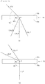
- FIG. 1 is a diagram schematically illustrating a relationship between an irradiation direction of each of a first laser and a second laser and a progress direction of light of each of the first laser and the second laser at a predetermined location
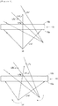
- FIG. 2 is a diagram schematically illustrating that a plurality of groups exists, in which cross angles between a progress direction of light of a first laser and the progress direction of light by a second laser at a predetermined location of a photosensitive area are different from each other in a manufacturing method of a holographic optical element according to an aspect of the present invention.
- a hologram is recorded by irradiating two lasers which are coherent to each other to a photosensitive substrate to manufacture the holographic optical element.
- the photosensitive substrate may be a film type including a photosensitive layer.
- the photosensitive layer may include a photosensitive material.
- various types of photosensitive materials are known, which may be used for replication of the holographic optical element and the material may be used even in the present invention without a limit.
- the photosensitive material a photopolymer, photoresist, silver halide emulsion, dichromated gelatin, photographic emulsion, photothermoplastic, or photorefractive material may be used.
- the photosensitive substrate may be an optically transparent film with non anisotropy and for example, a substrate including triacetyl cellulose (TAC), polyethylene (PE), polycarbonate (PC), polypropylene (PP), polyamide (PA), or polyethylene terephthalate (PET), but is not particularly limited.
- TAC triacetyl cellulose
- PE polyethylene
- PC polycarbonate
- PP polypropylene
- PA polyamide
- PET polyethylene terephthalate
- the holographic optical element to be manufactured through the manufacturing method according to an aspect of the present invention as a reflection type holographic optical element may be manufactured by a scheme of irradiating an object wave onto one surface of the photosensitive substrate and irradiating a reference wave onto another surface of the photosensitive substrate opposite to one surface.
- the manufacturing method of the holographic optical element according to an aspect of the present invention may include: irradiating a first laser in which light is spread in an irradiation direction on one surface of a photosensitive substrate; and irradiating a second laser in which light is collected in the irradiation direction on another surface of the photosensitive substrate, in which the first laser and the second laser may be irradiated so that a plurality of groups exists in which cross angles formed by a progress direction of the light by the first laser and the progress direction of the light by the second laser are different from each other at a predetermined location of a photosensitive area in which the light by the first laser and the light by the second laser cross on the photosensitive substrate.
- the first laser and the second laser may be simultaneously irradiated in order to use coherence.
- a plurality of holograms in which coherent characteristics are different from each other may be recorded at a predetermined location of the photosensitive substrate.
- light having a single wavelength is input into a reflection type holographic optical element manufactured by a manufacturing method according to an aspect of the present invention by using a projector/a light irradiation unit, holograms having different coherent characteristics at a predetermined location are recorded, and as a result, a plurality of different light reflection paths may be formed by reflection, thereby implementing a plurality of exit pupils.
- the first laser and the second laser may be irradiated as light the same single wavelength.
- a first laser L1 is a laser in which light is spread in the irradiation direction.
- the irradiation direction of the first laser L1 may mean a direction in which a line L1_c bisecting an angle ⁇ 1 formed by both outermost points B1a and B1b of light which is spread based on a cross section (based on (a) of FIG. 1 ) around a point A1 at which the light is collected extends in a direction in which the light is gradually spread.
- the progress direction of the light by the first laser L1 at a predetermined location P may mean a direction in which a line L1_P linking the point A1 at which the light is collected and the predetermined location P extends in the direction in which the light is gradually spread.
- a second laser L2 is a laser in which the light is collected in the irradiation direction.
- the irradiation direction of the second laser L2 may mean a direction in which a line L2_c bisecting an angle ⁇ 2 formed by both outermost points B2a and B2b of light which is spread based on a cross section (based on (b) of FIG. 1 ) around a point A2 at which the light is collected extends in a direction in which the light is gradually collected.
- the progress direction of the light by the second laser L2 at a predetermined location P may mean a direction in which a line L2_P linking the point A2 at which the light is collected and the predetermined location P extends in the direction in which the light is gradually collected.
- FIG. 2 it will be described that a plurality of groups exists, in which cross angles between a progress direction of light of a first laser and the progress direction of light by a second laser at a predetermined location of a photosensitive area are different from each other in a manufacturing method of a holographic optical element according to an aspect of the present invention.
- the first laser may be irradiated onto one surface 10a of a photosensitive substrate 10 and here, it is preferable that the first laser is irradiated a plurality of numbers of times simultaneously or in different orders so that a plurality of light in which the progress direction are different from each other reaches the predetermined location P of the photosensitive substrate 10 simultaneously or in different orders.
- the second laser may be irradiated onto another surface 10b of the photosensitive substrate 10.
- the progress direction of the light of the second laser reaching the predetermined location P of the photosensitive substrate 10 may be defined as a single progress direction L2_P and the progress direction of the light of the first laser reaching the predetermined location P of the photosensitive substrate 10 may be defined as a plurality of progress directions L1a_P, L1b_P, and L1c_P
- a plurality of groups L1a_P to L2_P, L1b_P to L2_P, and L1c_P to L2_P may consequently exist in which cross angles ⁇ a, ⁇ b, and ⁇ c formed by the progress direction of the light by the first laser and the progress direction of the light by the second laser at the predetermined location P of the photosensitive area in which the first laser and the second laser interfere with each other are different from each other.
- the first laser may be irradiated onto one surface 10a of the photosensitive substrate 10.
- the second laser may be irradiated onto another surface 10b of the photosensitive substrate 10 and here, the second laser may be irradiated a plurality of numbers of times simultaneously or in different orders so that a plurality of light in which the progress direction are different from each other reaches the predetermined location P of the photosensitive substrate 10 simultaneously or in different orders.
- the progress direction of the light of the first laser reaching the predetermined location P of the photosensitive substrate 10 may be defined as a single progress direction L1_P and the progress direction of the light of the second laser reaching the predetermined location P of the photosensitive substrate 10 may be defined as a plurality of progress directions L2a_P, and L2b_P
- a plurality of groups L1_P to L2a_P and L1_P to L2b_P may consequently exist in which cross angles ⁇ a' and ⁇ b' formed by the progress direction of the light by the first laser and the progress direction of the light by the second laser at the predetermined location P of the photosensitive area in which the first laser and the second laser interfere with each other are different from each other.
- FIG. 3 is a diagram illustrating an example of an irradiation method of a first laser and a second laser in the manufacturing method of the holographic optical element according to an aspect of the present invention.
- first lasers may be irradiated in which irradiation directions L1a_c, L1b_c, and L1c_c are parallel to each other at a plurality of locations which are spaced apart from each other in a width direction (a horizontal direction based on FIG. 3 ) of the photosensitive substrate 10.
- a plurality of first lasers L1a, L1b, and L1c may be irradiated simultaneously or in different orders.
- the second laser L2 may be irradiated simultaneously with each of the first lasers L1a, L1b,and L1c in order to record a hologram using coherence.
- a plurality of light L1a_P, L1b_P, L1c_P in which the progress directions by the plurality of first lasers L1a, L1b, and L1c are different from each other may reach at the predetermined location P of the photosensitive area and a plurality of groups L1a_P to L2_P, L1b_P to L2_P, and L1c_P to L2_P may exist in which cross angles formed by the progress direction of the light by the first lasers L1a, L1b, and L1c and the progress direction of the light by the second laser L2 at the predetermined location P in a relationship with the light L2_P reaching the predetermined location P by the second laser L2 are different from each other.
- FIG. 4 is a diagram illustrating another example of the irradiation method of the first laser and the second laser in the manufacturing method of the holographic optical element according to an aspect of the present invention.
- first lasers L1a' and L1b' are irradiated in different irradiation directions L1a'_c and L1b'_c and second lasers L2a' and L2b' are also irradiated in different irradiation direction L2a' c and L2b'_c.
- a cross angle ⁇ 4a formed by irradiation directions L1a'_c of any one first laser L1a' of the plurality of first lasers L1a' and L1b' and any one second laser L2a'_c of the plurality of second lasers may be the same as a cross angle ⁇ 4b formed by the irradiation directions L1b'_c and L2b'_c of any another first laser L1b' and any another second laser L2b'.
- first laser and the second laser are irradiated by such a method
- a plurality of groups may exist in which the cross angles formed by the progress direction of the light by the first laser and the progress direction of the light by the second laser are different from each other at the predetermined location P of the photosensitive area on the photosensitive substrate 10.
- FIG. 5 is a diagram illustrating yet another example of the irradiation method of the first laser and the second laser in the manufacturing method of the holographic optical element according to an aspect of the present invention.
- the irradiating of the first laser and the irradiating of the second laser may be performed a plurality of numbers of times while the photosensitive substrate 10 is rotated at a predetermined angle around a predetermined horizontal center line C (a direction vertical to a plane of FIG. 5 ). Even though the first laser L1' and the second laser L2' are irradiated by such a method, a plurality of groups may exist in which the cross angles formed by the progress direction of the light by the first laser and the progress direction of the light by the second laser are different from each other at the predetermined location P of the photosensitive area on the photosensitive substrate 10.
- FIG. 6 is a diagram illustrating one example of a display device according to another aspect of the present invention.
- the display device 1000 may include a lens unit 100 including a holographic optical element 110 manufactured by a manufacturing method of a holographic optical element according to another aspect of the present invention and a light irradiation unit 200 irradiating light Li_a and Li_b which is spread in the irradiation direction to the holographic optical element 110.
- the lens unit 100 allows external light of a natural system to be transmitted by arranging the holographic optical element 110 on one surface of a transparent glass substrate or a polymer resin substrate to allow a display user to recognize an object, a background, etc., of the natural system as it is and display light input through the light irradiation unit 200 as an imaginary image which is reflected by the reflection type holographic optical element 110 and floated on an object, a background, etc., of a natural system recognized by a user.
- the light irradiation unit 200 may irradiate light Li_a and Li_b which is spread at the substantially same angle as an angle ⁇ L2 at which the light of the second laser used at the time of manufacturing the holographic optical element according to an aspect of the present invention is collected.
- the light irradiation unit 200 may irradiate light Li_a and Li_b having a single wavelength. Specifically, the light irradiation unit 200 may irradiate the light having the same single wavelength as the second laser used at the time of manufacturing the holographic optical element according to an aspect of the present invention.
- a plurality of different light reflection paths Lo_a, Lo_a'; Lo_b, and Lo_b' may be formed by reflection even though the light having the single wavelength is irradiated and input to the lens unit 100, thereby implementing a plurality of exit pupils EP1, EP2, and EP3.
- the eye box may be larger and in the case of the display device 1000, since the plurality of exit pupils may be implemented, there is a plurality of exit pupils matched even though a location of an actual pupil for the lens unit 100 varies for each user, and as a result, there is an advantage in that the display device 1000 may be used according to users having various body conditions. Further, in implementing the plurality of exit pupils, the display device 1000 has an advantage in that a plurality of lasers irradiating light having different wavelengths need not be used.
- FIG. 7 is an image through which a result of forming the plurality of exit pupils by irradiating laser light having a specific wavelength to a lens unit including a holographic optical element manufactured by a first laser and a second laser having specific wavelengths may be verified.
- the holographic optical element in the embodiment are manufactured by using a first laser and a second laser having a wavelength of 532 nm and the laser having the wavelength of 532 nm is irradiated to the lens unit including the holographic optical element in the embodiment by the light irradiation unit to locate a screen S at a specific distance from the lens unit, and as a result, three exit pupils EP1, EP2, and EP2 are located on the screen.
Landscapes
- Physics & Mathematics (AREA)
- General Physics & Mathematics (AREA)
- Optics & Photonics (AREA)
- Holo Graphy (AREA)
- Diffracting Gratings Or Hologram Optical Elements (AREA)
- Overhead Projectors And Projection Screens (AREA)
- Devices For Indicating Variable Information By Combining Individual Elements (AREA)
Abstract
Description
- The present invention relates to a manufacturing method of a holographic optical element and a display device including the holographic optical element manufactured thereby.
- In recent years, with an increase in an interest in a display unit that implements augmented reality (AR), mixed reality (MR), or virtual reality (VR), there is a trend that a research into the display unit that implements the augmented reality (AR), mixed reality (MR), or virtual reality (VR) is actively performed. The display unit that implements the augmented reality, the mixed reality, or the virtual reality includes a diffractive light guide plate using a diffraction phenomenon based on a vibrational property of light.
- As the diffractive light guide plate, a type including a plurality of diffraction optical elements having a plurality of grid line patterns and a type including a holographic optical element as photosensitive material in which an interference pattern is recorded are primarily used.
- Meanwhile, in the case of the type including the diffraction optical element, color separation efficiency is low, and as a result, image crosstalk may occur. Further, in the case of the type including the diffraction optical element or the transmission type holographic optical element, overall optical loss may significantly occur.
- On the contrary, the type including a reflection type holographic optical element has a disadvantage that the color separation efficient is high, and optical loss is also smaller than that of the diffraction optical element/transmission type holographic optical element, but an exit pupil for determining a size of an eye box is small.
- The aforementioned background art as technical information which the inventors possess for driving embodiments of the present invention or acquires during a derivation process may not particularly be called known art opened to a general public before application of the embodiments of the present invention.
- The present invention has been made in an effort to provide a method for manufacturing a reflection type holographic optical element forming a plurality of exit pupils and a display device including the holographic optical element manufactured thereby.
- However, the object to be solved by the present invention is not limited to the aforementioned object and other objects, which are not mentioned above, will be apparent to a person having ordinary skill in the art from the following description.
- An embodiment according to an aspect of the present invention provides a manufacturing method of the holographic optical element, including: irradiating a first laser in which light is spread in an irradiation direction on one surface of a photosensitive substrate; and irradiating a second laser in which light is collected in the irradiation direction on another surface of the photosensitive substrate, in which the first laser and the second laser may be irradiated so that a plurality of groups exists in which cross angles formed by a progress direction of the light by the first laser and the progress direction of the light by the second laser are different from each other at a predetermined location of a photosensitive area in which the light by the first laser and the light by the second laser cross on the photosensitive substrate.
- An embodiment according to another aspect of the present invention provides a display device including: a lens unit including a holographic optical element manufactured by an embodiment according to another aspect of the present invention; and a light irradiation unit irradiating light which is spread in an irradiation direction to the holographic optical element, in which the light irradiation unit irradiates light which is spread at an angle which is the same as an angle at which light of a second laser is collected.
- Even though light having a single wavelength is input into a reflection type holographic optical element manufactured by a manufacturing method of a holographic optical element according to an aspect of the present invention by using a projector/a light irradiation unit, holograms having different coherent characteristics at a predetermined location are recorded, and as a result, a plurality of different light reflection paths may be formed by reflection, thereby implementing a plurality of exit pupils.
-
-
FIG. 1 is a diagram schematically illustrating a relationship between an irradiation direction of each of a first laser and a second laser and a progress direction of light of each of the first laser and the second laser at a predetermined location. -
FIG. 2 is a diagram schematically illustrating that a plurality of groups exists, in which cross angles between a progress direction of light of a first laser and the progress direction of light by a second laser at a predetermined location of a photosensitive area are different from each other in a manufacturing method of a holographic optical element according to an aspect of the present invention. -
FIG. 3 is a diagram illustrating one example of an irradiation method of a first laser and a second laser in the manufacturing method of the holographic optical element according to an aspect of the present invention. -
FIG. 4 is a diagram illustrating another example of the irradiation method of the first laser and the second laser in the manufacturing method of the holographic optical element according to an aspect of the present invention. -
FIG. 5 is a diagram illustrating yet another example of the irradiation method of the first laser and the second laser in the manufacturing method of the holographic optical element according to an aspect of the present invention. -
FIG. 6 is a diagram illustrating one example of a display device according to another aspect of the present invention. - An embodiment according to an aspect of the present invention provides a manufacturing method of the holographic optical element, including: irradiating a first laser in which light is spread in an irradiation direction on one surface of a photosensitive substrate; and irradiating a second laser in which light is collected in the irradiation direction on another surface of the photosensitive substrate, in which the first laser and the second laser may be irradiated so that a plurality of groups in which cross angles formed by a progress direction of the light by the first laser and the progress direction of the light by the second laser are different from each other at a predetermined location of a photosensitive area in which the light by the first laser and the light by the second laser cross on the photosensitive substrate.
- In the embodiment, in the irradiating of the first laser, a first laser may be irradiated in which the irradiation directions are parallel to each other at a plurality of locations separated from each other, respectively.
- In the embodiment, in the irradiating of the first laser, a plurality of first lasers in which the irradiation directions are different from each other may be irradiated, in the irradiating of the second laser, a plurality of second lasers in which the irradiation directions are different from each other may be irradiated, and a cross angle formed by the irradiation direction of any one first laser among the plurality of first lasers and the irradiation direction of any one second laser among the plurality of second lasers may be the same as the cross angle formed by the irradiation direction of any another first laser and the irradiation direction of any another second laser.
- In the embodiment, the irradiating of the first laser and the irradiating of the second laser may be performed a plurality of numbers of times while the photosensitive substrate is rotated at a predetermined angle interval based on a predetermined horizontal center line.
- An embodiment according to another aspect of the present invention provides a display device including: a lens unit including a holographic optical element manufactured by an embodiment according to an aspect of the present invention; and a light irradiation unit irradiating light which is spread in an irradiation direction to the holographic optical element, in which the light irradiation unit irradiates light which is spread at an angle which is the same as an angle at which light of a second laser is collected.
- In the embodiment, the light irradiation unit may irradiate image light having a single wavelength.
- The present invention will be apparent with reference to embodiments to be described below in detail together with the accompanying drawings. However, the present invention is not limited to the following exemplary embodiments but may be implemented in various different forms. The exemplary embodiments are provided only to make description of the present invention complete and to fully provide the scope of the present invention to a person having ordinary skill in the art to which the present invention pertains, and the present invention will be just defined by the appended claims. Meanwhile, it is also to be understood that the terminology used herein is for the purpose of describing embodiments only and is not intended to limit the present invention. In this specification, singular forms include even plural forms unless the context indicates otherwise. It is to be understood that the terms 'comprises' and/or 'comprising' used in this specification does not exclude presence or addition of one or more other components, steps, operations, and/or elements with respect to stated components, steps, operations, and/or elements. Terms including as first, second, and the like are used for describing various components, but the components are not limited by the terms. The terms are used only to discriminate one component from another component.
- Hereinafter, the present invention will be described in more detail with reference to the drawings.
-
FIG. 1 is a diagram schematically illustrating a relationship between an irradiation direction of each of a first laser and a second laser and a progress direction of light of each of the first laser and the second laser at a predetermined location andFIG. 2 is a diagram schematically illustrating that a plurality of groups exists, in which cross angles between a progress direction of light of a first laser and the progress direction of light by a second laser at a predetermined location of a photosensitive area are different from each other in a manufacturing method of a holographic optical element according to an aspect of the present invention. - In the manufacturing method of the holographic optical element according to an aspect of the present invention which is used for manufacturing the holographic optical element used for the display device implementing augmented reality, a hologram is recorded by irradiating two lasers which are coherent to each other to a photosensitive substrate to manufacture the holographic optical element.
- Meanwhile, the photosensitive substrate may be a film type including a photosensitive layer. Further, the photosensitive layer may include a photosensitive material. In a hologram related field, various types of photosensitive materials are known, which may be used for replication of the holographic optical element and the material may be used even in the present invention without a limit. For example, as the photosensitive material, a photopolymer, photoresist, silver halide emulsion, dichromated gelatin, photographic emulsion, photothermoplastic, or photorefractive material may be used. The photosensitive substrate may be an optically transparent film with non anisotropy and for example, a substrate including triacetyl cellulose (TAC), polyethylene (PE), polycarbonate (PC), polypropylene (PP), polyamide (PA), or polyethylene terephthalate (PET), but is not particularly limited.
- It is known that the holographic optical element to be manufactured through the manufacturing method according to an aspect of the present invention as a reflection type holographic optical element may be manufactured by a scheme of irradiating an object wave onto one surface of the photosensitive substrate and irradiating a reference wave onto another surface of the photosensitive substrate opposite to one surface.
- The manufacturing method of the holographic optical element according to an aspect of the present invention may include: irradiating a first laser in which light is spread in an irradiation direction on one surface of a photosensitive substrate; and irradiating a second laser in which light is collected in the irradiation direction on another surface of the photosensitive substrate, in which the first laser and the second laser may be irradiated so that a plurality of groups exists in which cross angles formed by a progress direction of the light by the first laser and the progress direction of the light by the second laser are different from each other at a predetermined location of a photosensitive area in which the light by the first laser and the light by the second laser cross on the photosensitive substrate. Here, the first laser and the second laser may be simultaneously irradiated in order to use coherence. As a result, a plurality of holograms in which coherent characteristics are different from each other may be recorded at a predetermined location of the photosensitive substrate. Even though light having a single wavelength is input into a reflection type holographic optical element manufactured by a manufacturing method according to an aspect of the present invention by using a projector/a light irradiation unit, holograms having different coherent characteristics at a predetermined location are recorded, and as a result, a plurality of different light reflection paths may be formed by reflection, thereby implementing a plurality of exit pupils.
- Here, the first laser and the second laser may be irradiated as light the same single wavelength.
- First, referring to
FIG. 1 , a relationship between an irradiation direction of each of a first laser and a second laser and a progress direction of light of each of the first laser and the second laser at a predetermined location will be described. - A first laser L1 is a laser in which light is spread in the irradiation direction. The irradiation direction of the first laser L1 may mean a direction in which a line L1_c bisecting an angle θ1 formed by both outermost points B1a and B1b of light which is spread based on a cross section (based on (a) of
FIG. 1 ) around a point A1 at which the light is collected extends in a direction in which the light is gradually spread. The progress direction of the light by the first laser L1 at a predetermined location P may mean a direction in which a line L1_P linking the point A1 at which the light is collected and the predetermined location P extends in the direction in which the light is gradually spread. - A second laser L2 is a laser in which the light is collected in the irradiation direction. The irradiation direction of the second laser L2 may mean a direction in which a line L2_c bisecting an angle θ2 formed by both outermost points B2a and B2b of light which is spread based on a cross section (based on (b) of
FIG. 1 ) around a point A2 at which the light is collected extends in a direction in which the light is gradually collected. The progress direction of the light by the second laser L2 at a predetermined location P may mean a direction in which a line L2_P linking the point A2 at which the light is collected and the predetermined location P extends in the direction in which the light is gradually collected. - Referring to
FIG. 2 , it will be described that a plurality of groups exists, in which cross angles between a progress direction of light of a first laser and the progress direction of light by a second laser at a predetermined location of a photosensitive area are different from each other in a manufacturing method of a holographic optical element according to an aspect of the present invention. - For example, as illustrated in (a) of
FIG. 2 , the first laser may be irradiated onto onesurface 10a of aphotosensitive substrate 10 and here, it is preferable that the first laser is irradiated a plurality of numbers of times simultaneously or in different orders so that a plurality of light in which the progress direction are different from each other reaches the predetermined location P of thephotosensitive substrate 10 simultaneously or in different orders. The second laser may be irradiated onto anothersurface 10b of thephotosensitive substrate 10. In this case, since the progress direction of the light of the second laser reaching the predetermined location P of thephotosensitive substrate 10 may be defined as a single progress direction L2_P and the progress direction of the light of the first laser reaching the predetermined location P of thephotosensitive substrate 10 may be defined as a plurality of progress directions L1a_P, L1b_P, and L1c_P, a plurality of groups L1a_P to L2_P, L1b_P to L2_P, and L1c_P to L2_P may consequently exist in which cross angles θa, θb, and θc formed by the progress direction of the light by the first laser and the progress direction of the light by the second laser at the predetermined location P of the photosensitive area in which the first laser and the second laser interfere with each other are different from each other. - As another example, as illustrated in (b) of
FIG. 2 , the first laser may be irradiated onto onesurface 10a of thephotosensitive substrate 10. The second laser may be irradiated onto anothersurface 10b of thephotosensitive substrate 10 and here, the second laser may be irradiated a plurality of numbers of times simultaneously or in different orders so that a plurality of light in which the progress direction are different from each other reaches the predetermined location P of thephotosensitive substrate 10 simultaneously or in different orders. In this case, since the progress direction of the light of the first laser reaching the predetermined location P of thephotosensitive substrate 10 may be defined as a single progress direction L1_P and the progress direction of the light of the second laser reaching the predetermined location P of thephotosensitive substrate 10 may be defined as a plurality of progress directions L2a_P, and L2b_P, a plurality of groups L1_P to L2a_P and L1_P to L2b_P may consequently exist in which cross angles θa' and θb' formed by the progress direction of the light by the first laser and the progress direction of the light by the second laser at the predetermined location P of the photosensitive area in which the first laser and the second laser interfere with each other are different from each other. -
FIG. 3 is a diagram illustrating an example of an irradiation method of a first laser and a second laser in the manufacturing method of the holographic optical element according to an aspect of the present invention. - Referring to
FIG. 3 , in the irradiating of the first laser, first lasers may be irradiated in which irradiation directions L1a_c, L1b_c, and L1c_c are parallel to each other at a plurality of locations which are spaced apart from each other in a width direction (a horizontal direction based onFIG. 3 ) of thephotosensitive substrate 10. In this case, a plurality of first lasers L1a, L1b, and L1c may be irradiated simultaneously or in different orders. However, the second laser L2 may be irradiated simultaneously with each of the first lasers L1a, L1b,and L1c in order to record a hologram using coherence. In this case, a plurality of light L1a_P, L1b_P, L1c_P in which the progress directions by the plurality of first lasers L1a, L1b, and L1c are different from each other may reach at the predetermined location P of the photosensitive area and a plurality of groups L1a_P to L2_P, L1b_P to L2_P, and L1c_P to L2_P may exist in which cross angles formed by the progress direction of the light by the first lasers L1a, L1b, and L1c and the progress direction of the light by the second laser L2 at the predetermined location P in a relationship with the light L2_P reaching the predetermined location P by the second laser L2 are different from each other. -
FIG. 4 is a diagram illustrating another example of the irradiation method of the first laser and the second laser in the manufacturing method of the holographic optical element according to an aspect of the present invention. - In the irradiating of the first laser, a plurality of first lasers may be irradiated in which the progress directions are different from each other and in the irradiating of the second laser, a plurality of second lasers may be irradiated in which the progress direction are different from each other. Referring to (a) and (b) of
FIGS. 4 , first lasers L1a' and L1b' are irradiated in different irradiation directions L1a'_c and L1b'_c and second lasers L2a' and L2b' are also irradiated in different irradiation direction L2a' c and L2b'_c. Meanwhile, a cross angle θ4a formed by irradiation directions L1a'_c of any one first laser L1a' of the plurality of first lasers L1a' and L1b' and any one second laser L2a'_c of the plurality of second lasers may be the same as a cross angle θ4b formed by the irradiation directions L1b'_c and L2b'_c of any another first laser L1b' and any another second laser L2b'. Even though the first laser and the second laser are irradiated by such a method, a plurality of groups may exist in which the cross angles formed by the progress direction of the light by the first laser and the progress direction of the light by the second laser are different from each other at the predetermined location P of the photosensitive area on thephotosensitive substrate 10. -
FIG. 5 is a diagram illustrating yet another example of the irradiation method of the first laser and the second laser in the manufacturing method of the holographic optical element according to an aspect of the present invention. - The irradiating of the first laser and the irradiating of the second laser may be performed a plurality of numbers of times while the
photosensitive substrate 10 is rotated at a predetermined angle around a predetermined horizontal center line C (a direction vertical to a plane ofFIG. 5 ). Even though the first laser L1' and the second laser L2' are irradiated by such a method, a plurality of groups may exist in which the cross angles formed by the progress direction of the light by the first laser and the progress direction of the light by the second laser are different from each other at the predetermined location P of the photosensitive area on thephotosensitive substrate 10. -
FIG. 6 is a diagram illustrating one example of a display device according to another aspect of the present invention. - The
display device 1000 according to another aspect of the present invention may include alens unit 100 including a holographicoptical element 110 manufactured by a manufacturing method of a holographic optical element according to another aspect of the present invention and alight irradiation unit 200 irradiating light Li_a and Li_b which is spread in the irradiation direction to the holographicoptical element 110. - The
lens unit 100 allows external light of a natural system to be transmitted by arranging the holographicoptical element 110 on one surface of a transparent glass substrate or a polymer resin substrate to allow a display user to recognize an object, a background, etc., of the natural system as it is and display light input through thelight irradiation unit 200 as an imaginary image which is reflected by the reflection type holographicoptical element 110 and floated on an object, a background, etc., of a natural system recognized by a user. - The
light irradiation unit 200 may irradiate light Li_a and Li_b which is spread at the substantially same angle as an angle θL2 at which the light of the second laser used at the time of manufacturing the holographic optical element according to an aspect of the present invention is collected. - The
light irradiation unit 200 may irradiate light Li_a and Li_b having a single wavelength. Specifically, thelight irradiation unit 200 may irradiate the light having the same single wavelength as the second laser used at the time of manufacturing the holographic optical element according to an aspect of the present invention. - In the
display device 1000 according to the embodiment of the present invention, since holograms in which coherent characteristics are different are recorded at a predetermined location P of the holographicoptical element 110, a plurality of different light reflection paths Lo_a, Lo_a'; Lo_b, and Lo_b' may be formed by reflection even though the light having the single wavelength is irradiated and input to thelens unit 100, thereby implementing a plurality of exit pupils EP1, EP2, and EP3. As the exit pupils of the light are more, the eye box may be larger and in the case of thedisplay device 1000, since the plurality of exit pupils may be implemented, there is a plurality of exit pupils matched even though a location of an actual pupil for thelens unit 100 varies for each user, and as a result, there is an advantage in that thedisplay device 1000 may be used according to users having various body conditions. Further, in implementing the plurality of exit pupils, thedisplay device 1000 has an advantage in that a plurality of lasers irradiating light having different wavelengths need not be used. -
FIG. 7 is an image through which a result of forming the plurality of exit pupils by irradiating laser light having a specific wavelength to a lens unit including a holographic optical element manufactured by a first laser and a second laser having specific wavelengths may be verified. - Specifically, it can be seen that the holographic optical element in the embodiment are manufactured by using a first laser and a second laser having a wavelength of 532 nm and the laser having the wavelength of 532 nm is irradiated to the lens unit including the holographic optical element in the embodiment by the light irradiation unit to locate a screen S at a specific distance from the lens unit, and as a result, three exit pupils EP1, EP2, and EP2 are located on the screen.
- Although the present invention has been described in connection with the preferred embodiments mentioned above, various modifications or variations can be made without departing from the spirit and the scope of the present invention. Accordingly, the modifications or variations will be included in the scope of the appended claims if the modifications or variations belong to the spirit of the present invention.
Claims (6)
- A manufacturing method of a holographic optical element, comprising:irradiating a first laser in which light is spread in an irradiation direction on one surface of a photosensitive substrate; andirradiating a second laser in which light is collected in the irradiation direction on another surface of the photosensitive substrate,wherein the first laser and the second laser are irradiated so that a plurality of groups exists in which cross angles formed by a progress direction of the light by the first laser and the progress direction of the light by the second laser are different from each other at a predetermined location of a photosensitive area in which the light by the first laser and the light by the second laser cross on the photosensitive substrate.
- The manufacturing method of a holographic optical element of claim 1, wherein in the irradiating of the first laser, a first laser is irradiated in which the irradiation directions are parallel to each other at a plurality of locations separated from each other, respectively.
- The manufacturing method of a holographic optical element of claim 1, wherein in the irradiating of the first laser, a plurality of first lasers in which the irradiation directions are different from each other is irradiated,
in the irradiating of the second laser, a plurality of second lasers in which the irradiation directions are different from each other is irradiated, and
a cross angle formed by the irradiation direction of any one first laser among the plurality of first lasers and the irradiation direction of any one second laser among the plurality of second lasers is the same as the cross angle formed by the irradiation direction of any another first laser and the irradiation direction of any another second laser. - The manufacturing method of a holographic optical element of claim 1, wherein the irradiating of the first laser and the irradiating of the second laser are performed a plurality of numbers of times while the photosensitive substrate is rotated at a predetermined angle based on a predetermined horizontal center line.
- A display device comprising:a lens unit including a holographic optical element manufactured by a manufacturing method of claim 1; anda light irradiation unit irradiating light which is spread in an irradiation direction to the holographic optical element,wherein the light irradiation unit irradiates light which is spread at an angle which is the same as an angle at which light of a second laser is collected.
- The display device of claim 5, wherein the light irradiation unit irradiates light having a single wavelength.
Applications Claiming Priority (2)
| Application Number | Priority Date | Filing Date | Title |
|---|---|---|---|
| KR1020180108650A KR102388925B1 (en) | 2018-09-12 | 2018-09-12 | Method for manufacturing holographic optical element and display device comprising holographic optical element manufactured by the same |
| PCT/KR2019/011691 WO2020055088A1 (en) | 2018-09-12 | 2019-09-10 | Method for manufacturing holographic optical element and display device including holographic optical element manufactured thereby |
Publications (2)
| Publication Number | Publication Date |
|---|---|
| EP3822695A1 true EP3822695A1 (en) | 2021-05-19 |
| EP3822695A4 EP3822695A4 (en) | 2021-09-15 |
Family
ID=69777933
Family Applications (1)
| Application Number | Title | Priority Date | Filing Date |
|---|---|---|---|
| EP19859355.0A Pending EP3822695A4 (en) | 2018-09-12 | 2019-09-10 | METHOD OF MANUFACTURING A HOLOGRAPHIC OPTICAL ELEMENT AND DISPLAY DEVICE INCLUDING A HOLOGRAPHIC OPTICAL ELEMENT THUS MANUFACTURED |
Country Status (6)
| Country | Link |
|---|---|
| US (1) | US11768461B2 (en) |
| EP (1) | EP3822695A4 (en) |
| JP (1) | JP7138785B2 (en) |
| KR (1) | KR102388925B1 (en) |
| CN (1) | CN112334816A (en) |
| WO (1) | WO2020055088A1 (en) |
Families Citing this family (2)
| Publication number | Priority date | Publication date | Assignee | Title |
|---|---|---|---|---|
| KR102866139B1 (en) * | 2020-08-25 | 2025-09-26 | 주식회사 엘지화학 | Holographic Optical Element and Method For Manufacturing Thereof |
| TWI901763B (en) * | 2020-09-14 | 2025-10-21 | 南韓商Lg化學股份有限公司 | Holographic optical element and production method therefor |
Family Cites Families (26)
| Publication number | Priority date | Publication date | Assignee | Title |
|---|---|---|---|---|
| JPS5281897A (en) | 1975-12-26 | 1977-07-08 | Furuno Electric Co | Automatic steering gear |
| JP3432235B2 (en) | 1992-03-31 | 2003-08-04 | 大日本印刷株式会社 | How to create a holographic filter |
| JP3873892B2 (en) | 2003-01-22 | 2007-01-31 | コニカミノルタホールディングス株式会社 | Video display device |
| US6870651B2 (en) * | 2003-05-30 | 2005-03-22 | Eastman Kodak Company | Apparatus and method for generating a dynamic image |
| JP4369743B2 (en) | 2003-12-26 | 2009-11-25 | Tdk株式会社 | Holographic multiple recording method, holographic recording apparatus and holographic recording medium using the same |
| KR100571840B1 (en) * | 2004-04-21 | 2006-04-17 | 삼성전자주식회사 | Device for recording / playback of holographic information |
| US20050275916A1 (en) | 2004-06-09 | 2005-12-15 | Alps Electric Co., Ltd. | Hologram device |
| JP4525663B2 (en) * | 2006-10-23 | 2010-08-18 | コニカミノルタホールディングス株式会社 | Hologram exposure apparatus and hologram exposure method |
| JP5526681B2 (en) | 2009-09-29 | 2014-06-18 | 大日本印刷株式会社 | Holographic optical element and method of manufacturing holographic optical element |
| JP5527310B2 (en) | 2010-11-16 | 2014-06-18 | 大日本印刷株式会社 | Illumination device, projection device, and projection-type image display device |
| KR20130022900A (en) | 2011-08-26 | 2013-03-07 | 엘지디스플레이 주식회사 | Display apparatus for displaying three dimensional picture |
| KR101946031B1 (en) * | 2012-02-15 | 2019-02-11 | 한국전자통신연구원 | Holographic display apparatus capable of steering view window |
| KR102005449B1 (en) * | 2012-12-27 | 2019-07-30 | 삼성전자주식회사 | Integrated hologram optical element |
| US20150362734A1 (en) * | 2013-01-28 | 2015-12-17 | Ecole Polytechnique Federale De Lausanne (Epfl) | Transflective holographic film for head worn display |
| KR20150136601A (en) * | 2013-03-25 | 2015-12-07 | 에꼴 뽈리떼끄닉 뻬데랄 드 로잔느 (으뻬에프엘) | Method for displaying an image projected from a head-worn display with multiple exit pupils |
| JP6229711B2 (en) | 2013-03-26 | 2017-11-15 | コニカミノルタ株式会社 | Video display device and head mounted display |
| TWI664447B (en) | 2014-02-18 | 2019-07-01 | 德商拜耳材料科學股份有限公司 | Autostereoscopic 3d display device using holographic optical elements |
| KR20160066942A (en) * | 2014-12-03 | 2016-06-13 | 서울대학교산학협력단 | Apparatus and method for manufacturing Holographic Optical Element |
| JP6439453B2 (en) | 2015-01-09 | 2018-12-19 | セイコーエプソン株式会社 | Image display device and method of manufacturing image display device |
| KR102437053B1 (en) | 2015-01-30 | 2022-08-29 | 네이버웹툰 유한회사 | Method, system and recording medium for providing sound source of internet cartoon content |
| US10175488B2 (en) * | 2015-05-04 | 2019-01-08 | North Inc. | Systems, devices, and methods for spatially-multiplexed holographic optical elements |
| DE102015109703B4 (en) | 2015-06-17 | 2022-03-17 | tooz technologies GmbH | Spectacle lens, spectacles and method for producing a spectacle lens |
| US20170102540A1 (en) * | 2015-10-12 | 2017-04-13 | Patrick Gerard McGlew | Variable reflectivity image combiner for wearable displays |
| US20180003961A1 (en) | 2016-07-01 | 2018-01-04 | Intel Corporation | Gaze detection in head worn display |
| KR101894017B1 (en) * | 2016-11-08 | 2018-08-31 | 서울대학교산학협력단 | Apparatus for manufacturing Holographic Optical Element, and apparatus for reconstruction of holograms |
| JP7358846B2 (en) * | 2019-08-28 | 2023-10-11 | セイコーエプソン株式会社 | Optical element manufacturing method, optical element and display device |
-
2018
- 2018-09-12 KR KR1020180108650A patent/KR102388925B1/en active Active
-
2019
- 2019-09-10 CN CN201980041979.8A patent/CN112334816A/en active Pending
- 2019-09-10 JP JP2021519519A patent/JP7138785B2/en active Active
- 2019-09-10 US US17/254,706 patent/US11768461B2/en active Active
- 2019-09-10 WO PCT/KR2019/011691 patent/WO2020055088A1/en not_active Ceased
- 2019-09-10 EP EP19859355.0A patent/EP3822695A4/en active Pending
Also Published As
| Publication number | Publication date |
|---|---|
| US11768461B2 (en) | 2023-09-26 |
| JP7138785B2 (en) | 2022-09-16 |
| WO2020055088A1 (en) | 2020-03-19 |
| JP2021528704A (en) | 2021-10-21 |
| US20210116862A1 (en) | 2021-04-22 |
| CN112334816A (en) | 2021-02-05 |
| EP3822695A4 (en) | 2021-09-15 |
| KR20200030173A (en) | 2020-03-20 |
| KR102388925B1 (en) | 2022-04-22 |
Similar Documents
| Publication | Publication Date | Title |
|---|---|---|
| EP3612914B1 (en) | Skew mirror auxiliary imaging | |
| JP7320686B2 (en) | Multilayer liquid crystal gratings for redirecting light over a wide range of incident angles | |
| US11914767B2 (en) | Glint-based eye tracker illumination using dual-sided and dual-layered architectures | |
| CN108885347B (en) | Pupil expansion | |
| KR102749459B1 (en) | 3d object rendering using detected features | |
| CN108351614A (en) | Holographic display device | |
| US20180129166A1 (en) | Holographic display apparatus for providing expanded viewing window | |
| JP7663612B2 (en) | Tunable attenuation of light transmission artifacts in wearable displays | |
| US20130120816A1 (en) | Thin flat type convergence lens | |
| US10527773B2 (en) | Backlight unit for holographic display apparatus and holographic display apparatus including the same | |
| US20250085560A1 (en) | Attenuation of light transmission artifacts in wearable displays | |
| EP3822695A1 (en) | Method for manufacturing holographic optical element and display device including holographic optical element manufactured thereby | |
| KR20120020955A (en) | Digital hologram image display device | |
| CN118525228A (en) | Replication of tilted surface relief gratings by optical proximity recording | |
| TWI862689B (en) | Device for manufacturing display lens, method for the same, and head mounted display device comprising display lens manufactured thereby | |
| US12339621B2 (en) | Augmented reality holographic display using optical waveguide and holographic optical element | |
| CN117741979A (en) | Near-eye display device and eye movement tracking method thereof | |
| US12546926B2 (en) | Holographic optical element, manufacturing method therefor and manufacturing device therefor | |
| KR102825825B1 (en) | Display device | |
| KR20130054204A (en) | Thin flat type converge lens |
Legal Events
| Date | Code | Title | Description |
|---|---|---|---|
| STAA | Information on the status of an ep patent application or granted ep patent |
Free format text: STATUS: THE INTERNATIONAL PUBLICATION HAS BEEN MADE |
|
| PUAI | Public reference made under article 153(3) epc to a published international application that has entered the european phase |
Free format text: ORIGINAL CODE: 0009012 |
|
| STAA | Information on the status of an ep patent application or granted ep patent |
Free format text: STATUS: REQUEST FOR EXAMINATION WAS MADE |
|
| 17P | Request for examination filed |
Effective date: 20210211 |
|
| AK | Designated contracting states |
Kind code of ref document: A1 Designated state(s): AL AT BE BG CH CY CZ DE DK EE ES FI FR GB GR HR HU IE IS IT LI LT LU LV MC MK MT NL NO PL PT RO RS SE SI SK SM TR |
|
| REG | Reference to a national code |
Ref country code: DE Ref legal event code: R079 Free format text: PREVIOUS MAIN CLASS: G02B0030000000 Ipc: G03H0001220000 |
|
| A4 | Supplementary search report drawn up and despatched |
Effective date: 20210813 |
|
| RIC1 | Information provided on ipc code assigned before grant |
Ipc: G02B 27/01 20060101ALI20210809BHEP Ipc: G03H 1/26 20060101ALI20210809BHEP Ipc: G03H 1/04 20060101ALI20210809BHEP Ipc: G02B 5/32 20060101ALI20210809BHEP Ipc: G03H 1/22 20060101AFI20210809BHEP |
|
| DAV | Request for validation of the european patent (deleted) | ||
| DAX | Request for extension of the european patent (deleted) | ||
| STAA | Information on the status of an ep patent application or granted ep patent |
Free format text: STATUS: EXAMINATION IS IN PROGRESS |
|
| 17Q | First examination report despatched |
Effective date: 20250212 |
|
| GRAP | Despatch of communication of intention to grant a patent |
Free format text: ORIGINAL CODE: EPIDOSNIGR1 |
|
| STAA | Information on the status of an ep patent application or granted ep patent |
Free format text: STATUS: GRANT OF PATENT IS INTENDED |