EP3822646A1 - Rf-hood for antenna measurements at low frequencies - Google Patents
Rf-hood for antenna measurements at low frequencies Download PDFInfo
- Publication number
- EP3822646A1 EP3822646A1 EP19209663.4A EP19209663A EP3822646A1 EP 3822646 A1 EP3822646 A1 EP 3822646A1 EP 19209663 A EP19209663 A EP 19209663A EP 3822646 A1 EP3822646 A1 EP 3822646A1
- Authority
- EP
- European Patent Office
- Prior art keywords
- conductor
- antenna
- under test
- dut
- hood
- Prior art date
- Legal status (The legal status is an assumption and is not a legal conclusion. Google has not performed a legal analysis and makes no representation as to the accuracy of the status listed.)
- Granted
Links
Images


Classifications
-
- G—PHYSICS
- G01—MEASURING; TESTING
- G01R—MEASURING ELECTRIC VARIABLES; MEASURING MAGNETIC VARIABLES
- G01R29/00—Arrangements for measuring or indicating electric quantities not covered by groups G01R19/00 - G01R27/00
- G01R29/08—Measuring electromagnetic field characteristics
- G01R29/0807—Measuring electromagnetic field characteristics characterised by the application
- G01R29/0814—Field measurements related to measuring influence on or from apparatus, components or humans, e.g. in ESD, EMI, EMC, EMP testing, measuring radiation leakage; detecting presence of micro- or radiowave emitters; dosimetry; testing shielding; measurements related to lightning
- G01R29/0821—Field measurements related to measuring influence on or from apparatus, components or humans, e.g. in ESD, EMI, EMC, EMP testing, measuring radiation leakage; detecting presence of micro- or radiowave emitters; dosimetry; testing shielding; measurements related to lightning rooms and test sites therefor, e.g. anechoic chambers, open field sites or TEM cells
Definitions
- a far-field gain measurement requires a prepared anechoic chamber as well as reference equipment like the standard-gain horn and is, therefore, inflexible and inappropriate for non-stationary use. Further, the far-field gain measurement suffers from multiple-path effects such as ripples on measured RF characteristics and is sensitive to alignment errors. Additionally, timing-problems for pulsed measurements may occur since the far-field gain measurement requires naturally relative long cables. Due to the relative long cables, also an additional calibration of the cables may be required to compensate a temperature dependency of the cables employed.
- cubical-shaped RF-Hoods comprising compacts dimensions have been designed for antenna measurements. These RF-Hoods are transportable and may be assembled and/or disassembled to an antenna/device under test, DUT. In consequence, these cubical-shaped RF-Hoods allow a compact measurement arrangement for an antenna, which allows measuring characteristic and performance of an antenna-feed, wherein the antenna feed may remain mounted on its current support structure or its current support environment. An anechoic chamber and long cables are rendered expendable by the employment of such a cubical RF-Hood for antenna measurements.
- cubical-shaped RF-Hoods must include absorber walls, which are arranged substantially perpendicular and, for low frequencies, relatively near to the antenna under test, DUT.
- absorber walls influence the measured DUT's RF-characteristics.
- the electromagnetic field distribution in front of a DUT applied to a cubical-shaped RF-Hood differs from the field distribution in front of the DUT under free space conditions.
- probe antenna and DUT may couple with each other due to their near-field arrangement and, therefore, influence the measurement results.
- An RF-Hood for antenna measurements at low frequencies comprises a waveguide and a first conductor coupled with the waveguide.
- the first conductor is formed by four electrically conductive walls, which form the lateral surfaces of a pyramidal frustum.
- a second conductor is formed by four electrically conductive walls, which form the lateral surfaces of a pyramidal frustum.
- the pyramidal frustum defined by the conductive walls of the first conductor may differ from the pyramidal frustum defined by the conductive walls of the second conductor.
- the second conductor is configured to be coupled with an antenna under test, DUT, wherein "coupled with an antenna” means that the second conductor is coupled directly with an antenna and/or is coupled with a device, e.g. a ground plate, which is arranged at the antenna.
- a device e.g. a ground plate
- coupling between the second conductor and the antenna may be realized as direct coupling or as indirect coupling employing additional means such as connecting devices, dielectrics, linkages, plates, antenna housings or sealing elements, wherein the antenna does not contact the second conductor as such.
- the pyramidal frustum formed by the electrically conductive walls of the first conductor and/or the pyramidal frustum formed by the electrically conductive walls the second conductor may have a rectangular, particularly quadratic, base.
- the RF-Hood may include a third conductor coupled with the first conductor and coupled with the second conductor.
- the third conductor can be formed by four electrically conductive walls, which define/form four, particularly lateral, surfaces of a cuboid.
- the four electrical conductive walls, which may form the third conductor can be arranged to form a tunnel or frame comprising a rectangular or quadratic cross-section profile.
- the base of the pyramidal frustum formed by the electrically conductive walls of the first conductor may be congruent to the base of the pyramidal frustum formed by the electrically conductive walls of the second conductor.
- the base of the pyramidal frustum formed by the electrically conductive walls of the first conductor can be shaped identical to the base of the pyramidal frustum formed by the electrically conductive walls of the second conductor.
- the base of the pyramidal frustum formed by the first conductor and/or the second conductor can be congruent/identically shaped to a base of the cuboid formed by the four electrically conductive walls of the third conductor.
- the first conductor and/or the second conductor and/or the third conductor can, at least partially, be covered with a microwave absorbing material.
- a microwave absorbing material In particular, an inner surface of the RF-Hood formed by the first conductor and the second conductor and/or the third conductor may be covered with a microwave absorbing material.
- microwave absorbing material may be arranged on at least a part of the surfaces of the first conductor and/or the second conductor and/or the third conductor.
- the volume enclosed by the first conductor may exceed/be greater than the volume enclosed by the second conductor.
- the second conductor may form an opening configured to be sealed by the antenna under test and/or by a device coupled with the antenna under test.
- This opening formed by the second conductor may be an opening turned-away from the base of the pyramidal frustum formed by the conductive walls of second conductor and/or turned-away form the waveguide coupled with the first conductor waveguide.
- the opening to be sealed by the antenna under test and/or by a device coupled with the antenna under test may be a plane parallel to the base of the pyramidal frustum formed by the conductive walls of the second conductor, wherein this plane is delineated by the four conductive walls.
- the conductive walls of the first conductor and/or of the second conductor are trapezoid-shaped conductive plates.
- the conductive walls of the third conductor can be rectangular-shaped conductive plates.
- angles of the conductive walls of the first conductor and/or the second conductor may be chosen such that a remaining RF-backscattering, which is not avoided/prevented by the microwave absorbing material, in a direction back to the antenna under test is significantly reduced if e.g. compared with cuboid RF-Hoods.
- the angles of the conductive walls of the first conductor and/or the second conductor may be chosen such that corresponding free space impedance (e.g. 377 Ohm) is realized in front of the antenna under test and indicated by a reference face, RF.
- a field distribution in front of the antenna under test is realized that equals the field distribution in front of the antenna under test under free-space conditions (both for Rx and Tx operation).
- the reference face, RF can be positioned in parallel to the antenna under test and/or in parallel with the device coupled with the antenna under test, e.g. with an antenna ground plate, which seals the opening of the second conductor.
- angles of the conductive walls of the first conductor and/or the second conductor may be chosen such that the RF-Hood realizes an impedance transformation such that the impedance in front of the antenna under test (e.g. within the reference face, RF) is transformed to the impedance of the waveguide coupled with the first conductor. This reduces backscattering from the waveguide and/or a probe antenna coupled with the waveguide back to the antenna under test.
- an angle ⁇ 1 enclosed by a conductive wall of the first conductor and an (imaginary) straight line or plane extending perpendicularly from the base of a pyramidal frustum formed by the conductive walls of the first conductor may be 39° +/- 5°, particularly 39°.
- an angle ⁇ 1 enclosed by a conductive wall of the first conductor and an (imaginary) straight line extending from the (imaginary/interpolated) spire of the pyramidal frustum formed by the conductive walls of the first conductor and perpendicularly meeting/passing/crossing the base of the pyramidal frustum formed by the conductive walls of the first conductor may be 39° +/- 5°, particularly 39°.
- an angle ⁇ 2 enclosed by a conductive wall of the second conductor and an (imaginary) straight line or plane extending perpendicularly from the base of a pyramidal frustum formed by the conductive walls of the second conductor may be 54° +/- 5°, particularly 54°.
- an angle ⁇ 2 enclosed by a conductive wall of the second conductor and an (imaginary) straight line extending from the (imaginary/interpolated) spire of the pyramidal frustum formed by the conductive walls of the second conductor and perpendicularly meeting/passing/crossing the base of the pyramidal frustum formed by the conductive walls of the second conductor may be 54° +/- 5°, particularly 54°.
- the reference face, RF in front of and/or spaced apart from the antenna under test featuring free-space impedance and the impedance transformation from the impedance in front of the antenna under test to the impedance of the waveguide are beneficial especially for low frequency measurements, e.g. around 435 MHz.
- a performance of known microwave absorbing materials is limited, particularly at relatively low frequencies.
- probe-antennas for low frequency measurements have to be comparatively large, which favors undesired backscattering or coupling. Since the double pyramidal frustum-shaped RF-Hood design reduces both negative effects, it is particularly advantageous for low frequency measurements.
- An antenna measurement system comprises a RF-Hood according to preceding description and an antenna under test, DUT.
- the antenna under test, DUT, and/or a device coupled with the antenna under test may seal an opening of the RF-Hood.
- the opening of the RF-Hood which is sealed by the antenna under test and/or devices coupled with the antenna under test, can be an opening of the second conductor.
- the opening to be sealed can be turned away from the first conductor and/or the turned away from the waveguide coupled to the first conductor.
- the antenna measurement system can be configured for Rx and/or Tx measurements.
- the antenna measurement system is optimized for antenna measurements at p band frequencies, particularly at/around 435 MHz.
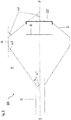
- Fig. 1 shows an antenna measurement system 100 optimized for antenna measurements at low frequencies, in particular for frequencies around 435 MHz.
- the shown system 100 comprises a RF-Hood coupled with a device/antenna under test DUT.
- the RF-Hood comprises a waveguide 10, a first conductor 12 and a second conductor 16.
- the waveguide 10 is implemented by a hollow conductive metal pipe comprising a rectangular cross-sectional area.
- the waveguide 10 is implemented as a chimney-shaped cuboid hollow metal tube comprising a cuboid through-opening for guiding RF-waves, particularly RF-waves of a frequency around 435 MHz, there through.
- the first conductor 12 is formed by four electrically conductive walls, which form the lateral surfaces of a pyramidal frustum. As shown, the first conductor 12 is coupled with the waveguide 10, wherein the waveguide 10 is arranged at an end of the first conductor 12 turned away from the quadratic base of the pyramidal frustum defined by the four conductive walls of the first conductor 12.
- the second conductor 16 is also formed by four electrically conductive walls, which form the lateral surfaces of a pyramidal frustum.
- the pyramidal frustum defined by the conductive walls of the first conductor 12 differs from the pyramidal frustum defined by the conductive walls of the second conductor 16.
- the first conductor 12 encloses a volume greater than the volume enclosed by the second conductor 16.
- the second conductor 16 is coupled with an antenna under test DUT. More precisely, the second conductor 16 is coupled with a ground plate of the antenna under test DUT.
- the shown RF-Hood includes a third conductor 14 coupled with the first conductor 12 and coupled with the second conductor 16, wherein the third conductor 16 is arranged between the first conductor 14 and the second conductor 16.
- the shown third conductor 14 is formed by four electrically conductive walls, which define four lateral surfaces of a cuboid, wherein the base of the formed cuboid is congruent/identical shaped to the quadratic basis of the pyramidal frustums defined by the conductive walls of the first and the second conductor 12, 16.
- the conductors 12, 14, 16 are integrally formed from a single work piece. However, this is explicitly not required by all embodiments of the invention.
- the conductors can be coupled or fixed to each other by mechanical means and/or coupled or fixed to each other permanently.
- the waveguide 10 and the conductors 12, 14, 16 form a double pyramidal frustum-shaped RF-Hood configured to couple with an antenna under test DUT.
- a microwave absorbing material 18 is arranged at the conductors 12, 14, 16. More precisely, the microwave absorbing material 18 covers an inner surface of the RF-Hood formed by the first conductor 12, the second conductor 16 and the third conductor 14.
- Fig. 2 shows that the waveguide 10 is coupled to a first opening of the RF-Hood, while a second opening of the RF-Hood is sealed by an antenna arrangement. More precisely, the ground plate coupled to the antenna under test DUT seals the second opening of the RF-Hood.
- Fig. 3 which shows the same arrangement as Fig. 2 , shows a reference face RF of the antenna under test spaced apart to the antenna under test DUT as such.
- the reference face RF is positioned/arranged in parallel to the antenna arrangement and/or to the antenna ground plate, which seals the opening of the second conductor 16.
- angles of the conductive walls of the shown first conductor 12 and the shown second conductor 16 are chosen such that a remaining RF-backscattering, which is not prevented by the microwave absorbing material 18 (not shown in Fig. 3 ), in a direction back to the antenna under test DUT is significantly reduced if compared with a cuboid RF-Hood.
- corresponding free space impedance e.g. 377 Ohm
- the angle ⁇ 1 is enclosed by a conductive wall of the first conductor and an (imaginary) straight line extending perpendicularly from the base of a pyramidal frustum formed by the conductive walls of the first conductor 12 is 39°.
- the angle ⁇ 2 enclosed by a conductive wall of the second conductor and an (imaginary) straight line extending perpendicularly from the base of a pyramidal frustum formed by the conductive walls of the second conductor 16 is 54°.
- the (imaginary) straight lines extending form the bases of the pyramidal frustums 12, 16 are in parallel to an (imaginary) straight line perpendicularly extending from the bases of the pyramidal frustums to (imaginary/interpolated) spires of the pyramidal frustums 12, 16.
- such a straight line is indicated by the axis X-X'.
- the angles of the conductive walls of the first conductor 12 and/or the second conductor 16 may be chosen such that the RF-Hood provides an impedance transformation such that the impedance in front of the antenna under test DUT (e.g. within the reference face, RF) is transformed to the impedance of the waveguide 10 coupled with the first conductor 12. This reduces backscattering from the waveguide 10 and/or a probe antenna coupled with the waveguide back to the antenna under test DUT.
- a measurement device may be coupled to the waveguide 10 (e.g. to a network vector analyzer, a power meter, a spectrum analyzer, etc.).
Landscapes
- Physics & Mathematics (AREA)
- Electromagnetism (AREA)
- General Physics & Mathematics (AREA)
- Measurement Of Resistance Or Impedance (AREA)
Abstract
Description
- In the following, a RF-Hood for antenna measurements at low frequencies and a corresponding antenna measurement system is disclosed.
- To measure characteristics and performance of an antenna at low frequencies, e.g. at frequencies around 435 MHz, several methods and devices are known. For a measurement of continuous wave signals, far-field gain measurement is the most common method. This method offers certain advantages. On the one hand, coupling between a probe antenna and the antenna under test, DUT, as such is minimized due to the far field arrangement. On the other hand, also the influence of absorber walls is reduced for the same reason. Further, the measurement arrangement may be calibrated with a reference antenna employing a standard-gain horn.
- However, a far-field gain measurement requires a prepared anechoic chamber as well as reference equipment like the standard-gain horn and is, therefore, inflexible and inappropriate for non-stationary use. Further, the far-field gain measurement suffers from multiple-path effects such as ripples on measured RF characteristics and is sensitive to alignment errors. Additionally, timing-problems for pulsed measurements may occur since the far-field gain measurement requires naturally relative long cables. Due to the relative long cables, also an additional calibration of the cables may be required to compensate a temperature dependency of the cables employed.
- To overcome these disadvantages cubical-shaped RF-Hoods comprising compacts dimensions have been designed for antenna measurements. These RF-Hoods are transportable and may be assembled and/or disassembled to an antenna/device under test, DUT. In consequence, these cubical-shaped RF-Hoods allow a compact measurement arrangement for an antenna, which allows measuring characteristic and performance of an antenna-feed, wherein the antenna feed may remain mounted on its current support structure or its current support environment. An anechoic chamber and long cables are rendered expendable by the employment of such a cubical RF-Hood for antenna measurements.
- However, such cubical-shaped RF-Hoods must include absorber walls, which are arranged substantially perpendicular and, for low frequencies, relatively near to the antenna under test, DUT. In consequence, these absorber walls influence the measured DUT's RF-characteristics. In particular, the electromagnetic field distribution in front of a DUT applied to a cubical-shaped RF-Hood differs from the field distribution in front of the DUT under free space conditions. Further, probe antenna and DUT may couple with each other due to their near-field arrangement and, therefore, influence the measurement results.
- Therefore, an enhanced RF-Hood optimized for characteristic and performance measurement of an antenna at low frequencies, e.g. frequencies around 435 MHz, is required.
- This problem is solved by a device according to claim 1. Further embodiments of the invention are defined by the dependent claims.
- An RF-Hood for antenna measurements at low frequencies comprises a waveguide and a first conductor coupled with the waveguide. The first conductor is formed by four electrically conductive walls, which form the lateral surfaces of a pyramidal frustum. A second conductor is formed by four electrically conductive walls, which form the lateral surfaces of a pyramidal frustum. The pyramidal frustum defined by the conductive walls of the first conductor may differ from the pyramidal frustum defined by the conductive walls of the second conductor.
- The second conductor is configured to be coupled with an antenna under test, DUT, wherein "coupled with an antenna" means that the second conductor is coupled directly with an antenna and/or is coupled with a device, e.g. a ground plate, which is arranged at the antenna. In other words, coupling between the second conductor and the antenna may be realized as direct coupling or as indirect coupling employing additional means such as connecting devices, dielectrics, linkages, plates, antenna housings or sealing elements, wherein the antenna does not contact the second conductor as such.
- The pyramidal frustum formed by the electrically conductive walls of the first conductor and/or the pyramidal frustum formed by the electrically conductive walls the second conductor may have a rectangular, particularly quadratic, base.
- Further, the RF-Hood may include a third conductor coupled with the first conductor and coupled with the second conductor. The third conductor can be formed by four electrically conductive walls, which define/form four, particularly lateral, surfaces of a cuboid. In other words, the four electrical conductive walls, which may form the third conductor, can be arranged to form a tunnel or frame comprising a rectangular or quadratic cross-section profile.
- The base of the pyramidal frustum formed by the electrically conductive walls of the first conductor may be congruent to the base of the pyramidal frustum formed by the electrically conductive walls of the second conductor. In other words, the base of the pyramidal frustum formed by the electrically conductive walls of the first conductor can be shaped identical to the base of the pyramidal frustum formed by the electrically conductive walls of the second conductor.
- Further, the base of the pyramidal frustum formed by the first conductor and/or the second conductor can be congruent/identically shaped to a base of the cuboid formed by the four electrically conductive walls of the third conductor.
- The first conductor and/or the second conductor and/or the third conductor can, at least partially, be covered with a microwave absorbing material. In particular, an inner surface of the RF-Hood formed by the first conductor and the second conductor and/or the third conductor may be covered with a microwave absorbing material. In an example, microwave absorbing material may be arranged on at least a part of the surfaces of the first conductor and/or the second conductor and/or the third conductor.
- In an example, the volume enclosed by the first conductor may exceed/be greater than the volume enclosed by the second conductor.
- The second conductor may form an opening configured to be sealed by the antenna under test and/or by a device coupled with the antenna under test. This opening formed by the second conductor may be an opening turned-away from the base of the pyramidal frustum formed by the conductive walls of second conductor and/or turned-away form the waveguide coupled with the first conductor waveguide. The opening to be sealed by the antenna under test and/or by a device coupled with the antenna under test may be a plane parallel to the base of the pyramidal frustum formed by the conductive walls of the second conductor, wherein this plane is delineated by the four conductive walls.
- The conductive walls of the first conductor and/or of the second conductor are trapezoid-shaped conductive plates. The conductive walls of the third conductor can be rectangular-shaped conductive plates.
- The angles of the conductive walls of the first conductor and/or the second conductor may be chosen such that a remaining RF-backscattering, which is not avoided/prevented by the microwave absorbing material, in a direction back to the antenna under test is significantly reduced if e.g. compared with cuboid RF-Hoods. In particular, the angles of the conductive walls of the first conductor and/or the second conductor may be chosen such that corresponding free space impedance (e.g. 377 Ohm) is realized in front of the antenna under test and indicated by a reference face, RF. As a consequence, a field distribution in front of the antenna under test is realized that equals the field distribution in front of the antenna under test under free-space conditions (both for Rx and Tx operation).
- The reference face, RF, can be positioned in parallel to the antenna under test and/or in parallel with the device coupled with the antenna under test, e.g. with an antenna ground plate, which seals the opening of the second conductor.
- Further, the angles of the conductive walls of the first conductor and/or the second conductor may be chosen such that the RF-Hood realizes an impedance transformation such that the impedance in front of the antenna under test (e.g. within the reference face, RF) is transformed to the impedance of the waveguide coupled with the first conductor. This reduces backscattering from the waveguide and/or a probe antenna coupled with the waveguide back to the antenna under test.
- In a variant, an angle α1 enclosed by a conductive wall of the first conductor and an (imaginary) straight line or plane extending perpendicularly from the base of a pyramidal frustum formed by the conductive walls of the first conductor may be 39° +/- 5°, particularly 39°. In other words, an angle α1 enclosed by a conductive wall of the first conductor and an (imaginary) straight line extending from the (imaginary/interpolated) spire of the pyramidal frustum formed by the conductive walls of the first conductor and perpendicularly meeting/passing/crossing the base of the pyramidal frustum formed by the conductive walls of the first conductor may be 39° +/- 5°, particularly 39°.
- Further, an angle α2 enclosed by a conductive wall of the second conductor and an (imaginary) straight line or plane extending perpendicularly from the base of a pyramidal frustum formed by the conductive walls of the second conductor may be 54° +/- 5°, particularly 54°. In other words, an angle α2 enclosed by a conductive wall of the second conductor and an (imaginary) straight line extending from the (imaginary/interpolated) spire of the pyramidal frustum formed by the conductive walls of the second conductor and perpendicularly meeting/passing/crossing the base of the pyramidal frustum formed by the conductive walls of the second conductor may be 54° +/- 5°, particularly 54°.
- Both above mentioned effects, the reference face, RF in front of and/or spaced apart from the antenna under test featuring free-space impedance and the impedance transformation from the impedance in front of the antenna under test to the impedance of the waveguide, are beneficial especially for low frequency measurements, e.g. around 435 MHz. On the one hand, a performance of known microwave absorbing materials is limited, particularly at relatively low frequencies. On the other hand, probe-antennas for low frequency measurements have to be comparatively large, which favors undesired backscattering or coupling. Since the double pyramidal frustum-shaped RF-Hood design reduces both negative effects, it is particularly advantageous for low frequency measurements.
- An antenna measurement system comprises a RF-Hood according to preceding description and an antenna under test, DUT.
- The antenna under test, DUT, and/or a device coupled with the antenna under test, e. g. connecting devices, dielectrics, linkages, plates, antenna housings or sealing elements, may seal an opening of the RF-Hood. The opening of the RF-Hood, which is sealed by the antenna under test and/or devices coupled with the antenna under test, can be an opening of the second conductor. Particularly, the opening to be sealed can be turned away from the first conductor and/or the turned away from the waveguide coupled to the first conductor.
- The antenna measurement system can be configured for Rx and/or Tx measurements.
- In an example, the antenna measurement system is optimized for antenna measurements at p band frequencies, particularly at/around 435 MHz.
- In the following, the present disclosure will further be described with reference to exemplary implementations illustrated in the figures, in which:
- Figure 1
- schematically illustrates an RF-Hood comprising a waveguide, a first conductor, a second conductor and a third conductor, wherein the shown RF-Hood is coupled with an antenna under test.
- Figure 2
- shows a cross-sectional view of the arrangement shown in
Fig. 1 along the imaginary cut axis X-X' shown inFig. 1 . - Figure 3
- shows the same cross-sectional view as
Fig. 2 , wherein, for the sake of clarity, some elements shown inFig. 2 are hidden while other elements not explicitly shown inFig. 2 are identified inFig. 3 . - In the following description, for purposes of explanation and not limitation, specific details are set forth in order to provide a thorough understanding of the present disclosure. It will be apparent to one skilled in the art that the present disclosure may be practiced in other implementations that depart from the specific details. Devices and device elements shown in the Figures, which are identified by the same reference sings, correspond to each other. Further, it is explicitly reminded that the figures are merely schematically drawn and, therefore, merely serve to identify essential features. In consequence, the absence of a feature in the figures shown does not imply the mandatory absence of a feature in an implementation of the invention defined by claim 1. In particular with view to the
Fig. 2 and3 , it is explicitly emphasized that all Figures show the same arrangement but each identify and hide different features of the arrangement shown. -
Fig. 1 shows anantenna measurement system 100 optimized for antenna measurements at low frequencies, in particular for frequencies around 435 MHz. The shownsystem 100 comprises a RF-Hood coupled with a device/antenna under test DUT. - The RF-Hood comprises a
waveguide 10, afirst conductor 12 and asecond conductor 16. - The
waveguide 10 is implemented by a hollow conductive metal pipe comprising a rectangular cross-sectional area. In other words, thewaveguide 10 is implemented as a chimney-shaped cuboid hollow metal tube comprising a cuboid through-opening for guiding RF-waves, particularly RF-waves of a frequency around 435 MHz, there through. - The
first conductor 12 is formed by four electrically conductive walls, which form the lateral surfaces of a pyramidal frustum. As shown, thefirst conductor 12 is coupled with thewaveguide 10, wherein thewaveguide 10 is arranged at an end of thefirst conductor 12 turned away from the quadratic base of the pyramidal frustum defined by the four conductive walls of thefirst conductor 12. - The
second conductor 16 is also formed by four electrically conductive walls, which form the lateral surfaces of a pyramidal frustum. However, the pyramidal frustum defined by the conductive walls of thefirst conductor 12 differs from the pyramidal frustum defined by the conductive walls of thesecond conductor 16. Particularly, thefirst conductor 12 encloses a volume greater than the volume enclosed by thesecond conductor 16. Thesecond conductor 16 is coupled with an antenna under test DUT. More precisely, thesecond conductor 16 is coupled with a ground plate of the antenna under test DUT. - Further, the shown RF-Hood includes a
third conductor 14 coupled with thefirst conductor 12 and coupled with thesecond conductor 16, wherein thethird conductor 16 is arranged between thefirst conductor 14 and thesecond conductor 16. The shownthird conductor 14 is formed by four electrically conductive walls, which define four lateral surfaces of a cuboid, wherein the base of the formed cuboid is congruent/identical shaped to the quadratic basis of the pyramidal frustums defined by the conductive walls of the first and thesecond conductor - In the shown examples, the
conductors - Together, the
waveguide 10 and theconductors - In
Fig. 2 , which shows a cross-sectional view along the axis X-X' schematically indicated inFig. 1 , it is shown that amicrowave absorbing material 18 is arranged at theconductors microwave absorbing material 18 covers an inner surface of the RF-Hood formed by thefirst conductor 12, thesecond conductor 16 and thethird conductor 14. - Further,
Fig. 2 shows that thewaveguide 10 is coupled to a first opening of the RF-Hood, while a second opening of the RF-Hood is sealed by an antenna arrangement. More precisely, the ground plate coupled to the antenna under test DUT seals the second opening of the RF-Hood. -
Fig. 3 , which shows the same arrangement asFig. 2 , shows a reference face RF of the antenna under test spaced apart to the antenna under test DUT as such. The reference face RF is positioned/arranged in parallel to the antenna arrangement and/or to the antenna ground plate, which seals the opening of thesecond conductor 16. - The angles of the conductive walls of the shown
first conductor 12 and the shownsecond conductor 16 are chosen such that a remaining RF-backscattering, which is not prevented by the microwave absorbing material 18 (not shown inFig. 3 ), in a direction back to the antenna under test DUT is significantly reduced if compared with a cuboid RF-Hood. Thus, corresponding free space impedance (e.g. 377 Ohm) is realized in front of the antenna under test at the shown reference face RF. - In the shown example, the angle α1 is enclosed by a conductive wall of the first conductor and an (imaginary) straight line extending perpendicularly from the base of a pyramidal frustum formed by the conductive walls of the
first conductor 12 is 39°. Further, the angle α2 enclosed by a conductive wall of the second conductor and an (imaginary) straight line extending perpendicularly from the base of a pyramidal frustum formed by the conductive walls of thesecond conductor 16 is 54°. The (imaginary) straight lines extending form the bases of thepyramidal frustums pyramidal frustums - The angles of the conductive walls of the
first conductor 12 and/or thesecond conductor 16 may be chosen such that the RF-Hood provides an impedance transformation such that the impedance in front of the antenna under test DUT (e.g. within the reference face, RF) is transformed to the impedance of thewaveguide 10 coupled with thefirst conductor 12. This reduces backscattering from thewaveguide 10 and/or a probe antenna coupled with the waveguide back to the antenna under test DUT. - For the characterization of the antenna under test DUT a measurement device may be coupled to the waveguide 10 (e.g. to a network vector analyzer, a power meter, a spectrum analyzer, etc.).
- In particular the following measurements can be performed:
- Measurement of input reflection of the antenna under test DUT under free-space conditions (Scattering parameters S11)
- Measurement of radiated power
- Measurement of signal distortions (Scattering parameters S21)
- Measurement of dual-polarized wave forms.
- It is believed that the advantages of the technique presented herein will be fully understood from the foregoing description, and it will be apparent that various changes may be made in the form, constructions and arrangement of the exemplary aspects thereof without departing from the scope of the disclosure or without sacrificing all of its advantageous effects. Because the technique presented herein can be varied in many ways, it will be recognized that the disclosure should be limited only by the scope of the claims that follow.
Claims (15)
- An RF-Hood for antenna measurements at low frequencies, comprisinga waveguide (10);a first conductor (12) coupled with the waveguide (10) formed by four electrically conductive walls forming lateral surfaces of a pyramidal frustum;a second conductor (16) formed by four electrically conductive walls forming lateral surfaces of a pyramidal frustum;
whereinthe second conductor (16) is configured to be coupled with an antenna under test (DUT). - The RF-Hood according any proceeding claim, wherein
the pyramidal frustum formed by the electrically conductive walls of the first conductor (12) and/or the second conductor (16) has a rectangular, particularly quadratic, base. - The RF-Hood according any proceeding claim, further comprising
a third conductor (14) coupled with the first conductor (12) and coupled with the second conductor (16), wherein
the third conductor is formed by four electrically conductive walls forming lateral surfaces of a cuboid, and/or
the base of the pyramidal frustum formed by the electrically conductive walls of the first conductor (12) is congruent to the base of the pyramidal frustum formed by the electrically conductive walls of the second conductor (16). - The RF-Hood according any proceeding claim, wherein
the base of the pyramidal frustum formed by the first conductor (12) and/or the second conductor (16) is congruent to a base of the cuboid formed by the four electrically conductive walls of the third conductor, and/or
the volume enclosed by the first conductor (12) exceeds the volume enclosed by the second conductor (16). - The RF-Hood according any proceeding claim, wherein
the first conductor (12) and/or the second conductor (16) and/or the third conductor (14) is covered with a microwave absorbing material (18). - The RF-Hood according any proceeding claim, wherein
the second conductor (16) forms an opening configured to be sealed by the antenna under test (DUT) and/or by a device coupled with the antenna under test (DUT). - The RF-Hood according any proceeding claim, wherein
a conductive wall of the first conductor (12) and a straight line extending perpendicularly from the base of the first conductor (12) enclose an angle α1, wherein the angle α1 is angle in the range of 34° to 43°, particularly 39°, and/or
a conductive wall of the second conductor (16) and a straight line extending perpendicularly from the base of the second conductor (16) enclose an angle a2, wherein the angle α2 is angle in the range of 49° to 58°, particularly 54°. - An Antenna measurement system (100) comprising
a RF-Hood according to any of the preceding claims; and
an antenna under test (DUT). - The antenna measurement system (100) according to claim 8, wherein
the antenna under test (DUT) and/or a device coupled with the antenna under test (DUT) seals an opening of the RF-Hood. - The antenna measurement system (100) according to claim 8 or 9, wherein
the opening of the RF-Hood, which is sealed by the antenna under test (DUT) and/or a device coupled with the antenna under test (DUT), is an opening of the second conductor (16) turned away from the first conductor (12) and/or the turned away from the waveguide (10) coupled to the first conductor. - The antenna measurement system (100) according to any of claims 8 to 10, further comprising
a reference face (RF) spaced apart from the antenna under test (DUT) - The antenna measurement system (100) according to claim 11,
wherein the reference face (RF) is in parallel to the antenna under test (DUT) and/or in parallel with the device coupled with the antenna under test (DUT), which seals the opening of the second conductor (16). - The antenna measurement system (100) according to any of the claims 8 to 12, wherein
the antenna measurement system (100) is configured for Rx and/or Tx measurements, and/or
the antenna measurement system (100) is configured for antenna measurements at frequencies in the p-band, particularly around 435 MHz. - The antenna measurement system (100) according to any of the claims 8 to 13, wherein
a free space impedance is realized in a reference face (RF) in front of the antenna under test (DUT). - The antenna measurement system (100) according to any of the claims 8 to 14, wherein
an impedance in front of the antenna under test (DUT) is transformed to an impedance of the waveguide (10) coupled with the first conductor (12).
Priority Applications (1)
| Application Number | Priority Date | Filing Date | Title |
|---|---|---|---|
| EP19209663.4A EP3822646B1 (en) | 2019-11-18 | 2019-11-18 | Rf-hood for antenna measurements at low frequencies |
Applications Claiming Priority (1)
| Application Number | Priority Date | Filing Date | Title |
|---|---|---|---|
| EP19209663.4A EP3822646B1 (en) | 2019-11-18 | 2019-11-18 | Rf-hood for antenna measurements at low frequencies |
Publications (2)
| Publication Number | Publication Date |
|---|---|
| EP3822646A1 true EP3822646A1 (en) | 2021-05-19 |
| EP3822646B1 EP3822646B1 (en) | 2023-08-30 |
Family
ID=68609938
Family Applications (1)
| Application Number | Title | Priority Date | Filing Date |
|---|---|---|---|
| EP19209663.4A Active EP3822646B1 (en) | 2019-11-18 | 2019-11-18 | Rf-hood for antenna measurements at low frequencies |
Country Status (1)
| Country | Link |
|---|---|
| EP (1) | EP3822646B1 (en) |
Citations (3)
| Publication number | Priority date | Publication date | Assignee | Title |
|---|---|---|---|---|
| DE2413373A1 (en) * | 1974-03-20 | 1975-09-25 | Deutsche Bundespost | Funnel shaped absorption chamber for aerial testing - with a cone shaped reflector round the exciting aerial |
| WO2003075020A1 (en) * | 2002-02-13 | 2003-09-12 | Tuhh Technologie Gmbh | Device for the detection of electromagnetic pulses with short rise times and high voltage amplitudes |
| US20130154887A1 (en) * | 2011-12-15 | 2013-06-20 | Paul W. Hein | Antenna testing enclosures and methods for testing antenna systems therewith |
-
2019
- 2019-11-18 EP EP19209663.4A patent/EP3822646B1/en active Active
Patent Citations (3)
| Publication number | Priority date | Publication date | Assignee | Title |
|---|---|---|---|---|
| DE2413373A1 (en) * | 1974-03-20 | 1975-09-25 | Deutsche Bundespost | Funnel shaped absorption chamber for aerial testing - with a cone shaped reflector round the exciting aerial |
| WO2003075020A1 (en) * | 2002-02-13 | 2003-09-12 | Tuhh Technologie Gmbh | Device for the detection of electromagnetic pulses with short rise times and high voltage amplitudes |
| US20130154887A1 (en) * | 2011-12-15 | 2013-06-20 | Paul W. Hein | Antenna testing enclosures and methods for testing antenna systems therewith |
Also Published As
| Publication number | Publication date |
|---|---|
| EP3822646B1 (en) | 2023-08-30 |
Similar Documents
| Publication | Publication Date | Title |
|---|---|---|
| CA2769881C (en) | Antenna characterisation in a waveguide | |
| US11444383B2 (en) | Antenna device, antenna system, and instrumentation system | |
| EP3012903A1 (en) | System for feeding high-frequency waves to deployment structure | |
| JP6179969B2 (en) | System for determining whether radio coverage is possible | |
| KR102085038B1 (en) | Shielding performance testing device of concrete block for electromagnetic shielding | |
| EP3822646B1 (en) | Rf-hood for antenna measurements at low frequencies | |
| SE515126C2 (en) | Testing apparatus and method for testing of transmission equipment | |
| KR100679084B1 (en) | Built-in partial discharge detection sensor in gas insulated switchgear | |
| Jadhav et al. | Design of X-band conical horn antenna using coaxial feed and improved design technique for bandwidth enhancement | |
| CN101527221B (en) | External GIS local discharge ultrahigh frequency monitoring sensor | |
| Cai et al. | Partial discharge detection approach for a medium voltage switchgear system | |
| Kotwal et al. | Modelling and analysis of gigahertz transverse electromagnetic mode (gtem) cell | |
| JP2002196027A (en) | Device for evaluating shielding effect and method for measuring shielding effect | |
| CN100516899C (en) | Method and arrangement for testing a radio device | |
| KR100666503B1 (en) | Epoxy inlet-type partial discharge detection sensor in gas insulated switchgear | |
| Kang et al. | Standard field generation system for calibration of Ka-band electric field probe | |
| US5397980A (en) | Current probe calibration fixture | |
| JPH1130638A (en) | Dark box for broadband electromagnetic wave test | |
| Li et al. | Reconfigurable Stripline in Anechoic Chamber for Electromagnetic Compatibility Testing | |
| Sen et al. | Broadband Calculable Dipole Antennas for SIL Measurements of CALTS | |
| Blackwell et al. | Operational Characteristics of a Plasma Antenna | |
| Battermann et al. | Influence of the receiving antenna pattern on the site-VSWR validation procedure above 1 GHz | |
| CN117054450A (en) | A rectangular waveguide device | |
| Werner et al. | Representation of absolute electric fieldstrength by superposition of radiated and guided waves | |
| CN119556011A (en) | System and method for measuring electromagnetic parameters of materials in strong microwave electric field environment based on parallel strip lines |
Legal Events
| Date | Code | Title | Description |
|---|---|---|---|
| PUAI | Public reference made under article 153(3) epc to a published international application that has entered the european phase |
Free format text: ORIGINAL CODE: 0009012 |
|
| STAA | Information on the status of an ep patent application or granted ep patent |
Free format text: STATUS: THE APPLICATION HAS BEEN PUBLISHED |
|
| AK | Designated contracting states |
Kind code of ref document: A1 Designated state(s): AL AT BE BG CH CY CZ DE DK EE ES FI FR GB GR HR HU IE IS IT LI LT LU LV MC MK MT NL NO PL PT RO RS SE SI SK SM TR |
|
| STAA | Information on the status of an ep patent application or granted ep patent |
Free format text: STATUS: REQUEST FOR EXAMINATION WAS MADE |
|
| 17P | Request for examination filed |
Effective date: 20210624 |
|
| RBV | Designated contracting states (corrected) |
Designated state(s): AL AT BE BG CH CY CZ DE DK EE ES FI FR GB GR HR HU IE IS IT LI LT LU LV MC MK MT NL NO PL PT RO RS SE SI SK SM TR |
|
| GRAP | Despatch of communication of intention to grant a patent |
Free format text: ORIGINAL CODE: EPIDOSNIGR1 |
|
| STAA | Information on the status of an ep patent application or granted ep patent |
Free format text: STATUS: GRANT OF PATENT IS INTENDED |
|
| INTG | Intention to grant announced |
Effective date: 20230403 |
|
| GRAS | Grant fee paid |
Free format text: ORIGINAL CODE: EPIDOSNIGR3 |
|
| GRAA | (expected) grant |
Free format text: ORIGINAL CODE: 0009210 |
|
| STAA | Information on the status of an ep patent application or granted ep patent |
Free format text: STATUS: THE PATENT HAS BEEN GRANTED |
|
| AK | Designated contracting states |
Kind code of ref document: B1 Designated state(s): AL AT BE BG CH CY CZ DE DK EE ES FI FR GB GR HR HU IE IS IT LI LT LU LV MC MK MT NL NO PL PT RO RS SE SI SK SM TR |
|
| REG | Reference to a national code |
Ref country code: GB Ref legal event code: FG4D |
|
| REG | Reference to a national code |
Ref country code: CH Ref legal event code: EP |
|
| REG | Reference to a national code |
Ref country code: DE Ref legal event code: R096 Ref document number: 602019036028 Country of ref document: DE |
|
| REG | Reference to a national code |
Ref country code: IE Ref legal event code: FG4D |
|
| REG | Reference to a national code |
Ref country code: LT Ref legal event code: MG9D |
|
| REG | Reference to a national code |
Ref country code: NL Ref legal event code: MP Effective date: 20230830 |
|
| REG | Reference to a national code |
Ref country code: AT Ref legal event code: MK05 Ref document number: 1606108 Country of ref document: AT Kind code of ref document: T Effective date: 20230830 |
|
| PG25 | Lapsed in a contracting state [announced via postgrant information from national office to epo] |
Ref country code: GR Free format text: LAPSE BECAUSE OF FAILURE TO SUBMIT A TRANSLATION OF THE DESCRIPTION OR TO PAY THE FEE WITHIN THE PRESCRIBED TIME-LIMIT Effective date: 20231201 |
|
| PG25 | Lapsed in a contracting state [announced via postgrant information from national office to epo] |
Ref country code: IS Free format text: LAPSE BECAUSE OF FAILURE TO SUBMIT A TRANSLATION OF THE DESCRIPTION OR TO PAY THE FEE WITHIN THE PRESCRIBED TIME-LIMIT Effective date: 20231230 |
|
| PG25 | Lapsed in a contracting state [announced via postgrant information from national office to epo] |
Ref country code: SE Free format text: LAPSE BECAUSE OF FAILURE TO SUBMIT A TRANSLATION OF THE DESCRIPTION OR TO PAY THE FEE WITHIN THE PRESCRIBED TIME-LIMIT Effective date: 20230830 Ref country code: RS Free format text: LAPSE BECAUSE OF FAILURE TO SUBMIT A TRANSLATION OF THE DESCRIPTION OR TO PAY THE FEE WITHIN THE PRESCRIBED TIME-LIMIT Effective date: 20230830 Ref country code: NO Free format text: LAPSE BECAUSE OF FAILURE TO SUBMIT A TRANSLATION OF THE DESCRIPTION OR TO PAY THE FEE WITHIN THE PRESCRIBED TIME-LIMIT Effective date: 20231130 Ref country code: LV Free format text: LAPSE BECAUSE OF FAILURE TO SUBMIT A TRANSLATION OF THE DESCRIPTION OR TO PAY THE FEE WITHIN THE PRESCRIBED TIME-LIMIT Effective date: 20230830 Ref country code: LT Free format text: LAPSE BECAUSE OF FAILURE TO SUBMIT A TRANSLATION OF THE DESCRIPTION OR TO PAY THE FEE WITHIN THE PRESCRIBED TIME-LIMIT Effective date: 20230830 Ref country code: IS Free format text: LAPSE BECAUSE OF FAILURE TO SUBMIT A TRANSLATION OF THE DESCRIPTION OR TO PAY THE FEE WITHIN THE PRESCRIBED TIME-LIMIT Effective date: 20231230 Ref country code: HR Free format text: LAPSE BECAUSE OF FAILURE TO SUBMIT A TRANSLATION OF THE DESCRIPTION OR TO PAY THE FEE WITHIN THE PRESCRIBED TIME-LIMIT Effective date: 20230830 Ref country code: GR Free format text: LAPSE BECAUSE OF FAILURE TO SUBMIT A TRANSLATION OF THE DESCRIPTION OR TO PAY THE FEE WITHIN THE PRESCRIBED TIME-LIMIT Effective date: 20231201 Ref country code: FI Free format text: LAPSE BECAUSE OF FAILURE TO SUBMIT A TRANSLATION OF THE DESCRIPTION OR TO PAY THE FEE WITHIN THE PRESCRIBED TIME-LIMIT Effective date: 20230830 Ref country code: AT Free format text: LAPSE BECAUSE OF FAILURE TO SUBMIT A TRANSLATION OF THE DESCRIPTION OR TO PAY THE FEE WITHIN THE PRESCRIBED TIME-LIMIT Effective date: 20230830 |
|
| PG25 | Lapsed in a contracting state [announced via postgrant information from national office to epo] |
Ref country code: PL Free format text: LAPSE BECAUSE OF FAILURE TO SUBMIT A TRANSLATION OF THE DESCRIPTION OR TO PAY THE FEE WITHIN THE PRESCRIBED TIME-LIMIT Effective date: 20230830 Ref country code: NL Free format text: LAPSE BECAUSE OF FAILURE TO SUBMIT A TRANSLATION OF THE DESCRIPTION OR TO PAY THE FEE WITHIN THE PRESCRIBED TIME-LIMIT Effective date: 20230830 |
|
| PG25 | Lapsed in a contracting state [announced via postgrant information from national office to epo] |
Ref country code: ES Free format text: LAPSE BECAUSE OF FAILURE TO SUBMIT A TRANSLATION OF THE DESCRIPTION OR TO PAY THE FEE WITHIN THE PRESCRIBED TIME-LIMIT Effective date: 20230830 |
|
| PG25 | Lapsed in a contracting state [announced via postgrant information from national office to epo] |
Ref country code: SM Free format text: LAPSE BECAUSE OF FAILURE TO SUBMIT A TRANSLATION OF THE DESCRIPTION OR TO PAY THE FEE WITHIN THE PRESCRIBED TIME-LIMIT Effective date: 20230830 Ref country code: RO Free format text: LAPSE BECAUSE OF FAILURE TO SUBMIT A TRANSLATION OF THE DESCRIPTION OR TO PAY THE FEE WITHIN THE PRESCRIBED TIME-LIMIT Effective date: 20230830 Ref country code: ES Free format text: LAPSE BECAUSE OF FAILURE TO SUBMIT A TRANSLATION OF THE DESCRIPTION OR TO PAY THE FEE WITHIN THE PRESCRIBED TIME-LIMIT Effective date: 20230830 Ref country code: EE Free format text: LAPSE BECAUSE OF FAILURE TO SUBMIT A TRANSLATION OF THE DESCRIPTION OR TO PAY THE FEE WITHIN THE PRESCRIBED TIME-LIMIT Effective date: 20230830 Ref country code: DK Free format text: LAPSE BECAUSE OF FAILURE TO SUBMIT A TRANSLATION OF THE DESCRIPTION OR TO PAY THE FEE WITHIN THE PRESCRIBED TIME-LIMIT Effective date: 20230830 Ref country code: CZ Free format text: LAPSE BECAUSE OF FAILURE TO SUBMIT A TRANSLATION OF THE DESCRIPTION OR TO PAY THE FEE WITHIN THE PRESCRIBED TIME-LIMIT Effective date: 20230830 Ref country code: SK Free format text: LAPSE BECAUSE OF FAILURE TO SUBMIT A TRANSLATION OF THE DESCRIPTION OR TO PAY THE FEE WITHIN THE PRESCRIBED TIME-LIMIT Effective date: 20230830 Ref country code: PT Free format text: LAPSE BECAUSE OF FAILURE TO SUBMIT A TRANSLATION OF THE DESCRIPTION OR TO PAY THE FEE WITHIN THE PRESCRIBED TIME-LIMIT Effective date: 20240102 |
|
| REG | Reference to a national code |
Ref country code: DE Ref legal event code: R097 Ref document number: 602019036028 Country of ref document: DE |
|
| REG | Reference to a national code |
Ref country code: CH Ref legal event code: PL |
|
| PG25 | Lapsed in a contracting state [announced via postgrant information from national office to epo] |
Ref country code: MC Free format text: LAPSE BECAUSE OF FAILURE TO SUBMIT A TRANSLATION OF THE DESCRIPTION OR TO PAY THE FEE WITHIN THE PRESCRIBED TIME-LIMIT Effective date: 20230830 |
|
| PLBE | No opposition filed within time limit |
Free format text: ORIGINAL CODE: 0009261 |
|
| STAA | Information on the status of an ep patent application or granted ep patent |
Free format text: STATUS: NO OPPOSITION FILED WITHIN TIME LIMIT |
|
| PG25 | Lapsed in a contracting state [announced via postgrant information from national office to epo] |
Ref country code: LU Free format text: LAPSE BECAUSE OF NON-PAYMENT OF DUE FEES Effective date: 20231118 |
|
| PG25 | Lapsed in a contracting state [announced via postgrant information from national office to epo] |
Ref country code: CH Free format text: LAPSE BECAUSE OF NON-PAYMENT OF DUE FEES Effective date: 20231130 |
|
| PG25 | Lapsed in a contracting state [announced via postgrant information from national office to epo] |
Ref country code: MC Free format text: LAPSE BECAUSE OF FAILURE TO SUBMIT A TRANSLATION OF THE DESCRIPTION OR TO PAY THE FEE WITHIN THE PRESCRIBED TIME-LIMIT Effective date: 20230830 Ref country code: LU Free format text: LAPSE BECAUSE OF NON-PAYMENT OF DUE FEES Effective date: 20231118 Ref country code: CH Free format text: LAPSE BECAUSE OF NON-PAYMENT OF DUE FEES Effective date: 20231130 Ref country code: SI Free format text: LAPSE BECAUSE OF FAILURE TO SUBMIT A TRANSLATION OF THE DESCRIPTION OR TO PAY THE FEE WITHIN THE PRESCRIBED TIME-LIMIT Effective date: 20230830 |
|
| REG | Reference to a national code |
Ref country code: BE Ref legal event code: MM Effective date: 20231130 |
|
| 26N | No opposition filed |
Effective date: 20240603 |
|
| REG | Reference to a national code |
Ref country code: IE Ref legal event code: MM4A |
|
| PG25 | Lapsed in a contracting state [announced via postgrant information from national office to epo] |
Ref country code: IE Free format text: LAPSE BECAUSE OF NON-PAYMENT OF DUE FEES Effective date: 20231118 |
|
| PG25 | Lapsed in a contracting state [announced via postgrant information from national office to epo] |
Ref country code: BE Free format text: LAPSE BECAUSE OF NON-PAYMENT OF DUE FEES Effective date: 20231130 |
|
| PG25 | Lapsed in a contracting state [announced via postgrant information from national office to epo] |
Ref country code: IE Free format text: LAPSE BECAUSE OF NON-PAYMENT OF DUE FEES Effective date: 20231118 Ref country code: BE Free format text: LAPSE BECAUSE OF NON-PAYMENT OF DUE FEES Effective date: 20231130 |
|
| PG25 | Lapsed in a contracting state [announced via postgrant information from national office to epo] |
Ref country code: BG Free format text: LAPSE BECAUSE OF FAILURE TO SUBMIT A TRANSLATION OF THE DESCRIPTION OR TO PAY THE FEE WITHIN THE PRESCRIBED TIME-LIMIT Effective date: 20230830 |
|
| PG25 | Lapsed in a contracting state [announced via postgrant information from national office to epo] |
Ref country code: BG Free format text: LAPSE BECAUSE OF FAILURE TO SUBMIT A TRANSLATION OF THE DESCRIPTION OR TO PAY THE FEE WITHIN THE PRESCRIBED TIME-LIMIT Effective date: 20230830 |
|
| PG25 | Lapsed in a contracting state [announced via postgrant information from national office to epo] |
Ref country code: CY Free format text: LAPSE BECAUSE OF FAILURE TO SUBMIT A TRANSLATION OF THE DESCRIPTION OR TO PAY THE FEE WITHIN THE PRESCRIBED TIME-LIMIT; INVALID AB INITIO Effective date: 20191118 |
|
| PG25 | Lapsed in a contracting state [announced via postgrant information from national office to epo] |
Ref country code: HU Free format text: LAPSE BECAUSE OF FAILURE TO SUBMIT A TRANSLATION OF THE DESCRIPTION OR TO PAY THE FEE WITHIN THE PRESCRIBED TIME-LIMIT; INVALID AB INITIO Effective date: 20191118 |
|
| PG25 | Lapsed in a contracting state [announced via postgrant information from national office to epo] |
Ref country code: TR Free format text: LAPSE BECAUSE OF FAILURE TO SUBMIT A TRANSLATION OF THE DESCRIPTION OR TO PAY THE FEE WITHIN THE PRESCRIBED TIME-LIMIT Effective date: 20230830 |
|
| PGFP | Annual fee paid to national office [announced via postgrant information from national office to epo] |
Ref country code: DE Payment date: 20251119 Year of fee payment: 7 |
|
| PGFP | Annual fee paid to national office [announced via postgrant information from national office to epo] |
Ref country code: GB Payment date: 20251121 Year of fee payment: 7 |
|
| PGFP | Annual fee paid to national office [announced via postgrant information from national office to epo] |
Ref country code: IT Payment date: 20251125 Year of fee payment: 7 |
|
| PGFP | Annual fee paid to national office [announced via postgrant information from national office to epo] |
Ref country code: FR Payment date: 20251126 Year of fee payment: 7 |