EP3822620B1 - Apparatus and method of imaging a heterogeneous object - Google Patents
Apparatus and method of imaging a heterogeneous object Download PDFInfo
- Publication number
- EP3822620B1 EP3822620B1 EP20171871.5A EP20171871A EP3822620B1 EP 3822620 B1 EP3822620 B1 EP 3822620B1 EP 20171871 A EP20171871 A EP 20171871A EP 3822620 B1 EP3822620 B1 EP 3822620B1
- Authority
- EP
- European Patent Office
- Prior art keywords
- gas
- chamber
- fixture
- images
- pressure
- Prior art date
- Legal status (The legal status is an assumption and is not a legal conclusion. Google has not performed a legal analysis and makes no representation as to the accuracy of the status listed.)
- Active
Links
Images


Classifications
-
- G—PHYSICS
- G01—MEASURING; TESTING
- G01N—INVESTIGATING OR ANALYSING MATERIALS BY DETERMINING THEIR CHEMICAL OR PHYSICAL PROPERTIES
- G01N23/00—Investigating or analysing materials by the use of wave or particle radiation, e.g. X-rays or neutrons, not covered by groups G01N3/00 – G01N17/00, G01N21/00 or G01N22/00
- G01N23/02—Investigating or analysing materials by the use of wave or particle radiation, e.g. X-rays or neutrons, not covered by groups G01N3/00 – G01N17/00, G01N21/00 or G01N22/00 by transmitting the radiation through the material
- G01N23/04—Investigating or analysing materials by the use of wave or particle radiation, e.g. X-rays or neutrons, not covered by groups G01N3/00 – G01N17/00, G01N21/00 or G01N22/00 by transmitting the radiation through the material and forming images of the material
- G01N23/046—Investigating or analysing materials by the use of wave or particle radiation, e.g. X-rays or neutrons, not covered by groups G01N3/00 – G01N17/00, G01N21/00 or G01N22/00 by transmitting the radiation through the material and forming images of the material using tomography, e.g. computed tomography [CT]
-
- A—HUMAN NECESSITIES
- A61—MEDICAL OR VETERINARY SCIENCE; HYGIENE
- A61B—DIAGNOSIS; SURGERY; IDENTIFICATION
- A61B6/00—Apparatus or devices for radiation diagnosis; Apparatus or devices for radiation diagnosis combined with radiation therapy equipment
- A61B6/02—Arrangements for diagnosis sequentially in different planes; Stereoscopic radiation diagnosis
- A61B6/03—Computed tomography [CT]
- A61B6/032—Transmission computed tomography [CT]
-
- A—HUMAN NECESSITIES
- A61—MEDICAL OR VETERINARY SCIENCE; HYGIENE
- A61B—DIAGNOSIS; SURGERY; IDENTIFICATION
- A61B6/00—Apparatus or devices for radiation diagnosis; Apparatus or devices for radiation diagnosis combined with radiation therapy equipment
- A61B6/12—Arrangements for detecting or locating foreign bodies
-
- A—HUMAN NECESSITIES
- A61—MEDICAL OR VETERINARY SCIENCE; HYGIENE
- A61B—DIAGNOSIS; SURGERY; IDENTIFICATION
- A61B6/00—Apparatus or devices for radiation diagnosis; Apparatus or devices for radiation diagnosis combined with radiation therapy equipment
- A61B6/48—Diagnostic techniques
- A61B6/488—Diagnostic techniques involving pre-scan acquisition
-
- A—HUMAN NECESSITIES
- A61—MEDICAL OR VETERINARY SCIENCE; HYGIENE
- A61B—DIAGNOSIS; SURGERY; IDENTIFICATION
- A61B6/00—Apparatus or devices for radiation diagnosis; Apparatus or devices for radiation diagnosis combined with radiation therapy equipment
- A61B6/50—Apparatus or devices for radiation diagnosis; Apparatus or devices for radiation diagnosis combined with radiation therapy equipment specially adapted for specific body parts; specially adapted for specific clinical applications
- A61B6/504—Apparatus or devices for radiation diagnosis; Apparatus or devices for radiation diagnosis combined with radiation therapy equipment specially adapted for specific body parts; specially adapted for specific clinical applications for diagnosis of blood vessels, e.g. by angiography
-
- G—PHYSICS
- G01—MEASURING; TESTING
- G01N—INVESTIGATING OR ANALYSING MATERIALS BY DETERMINING THEIR CHEMICAL OR PHYSICAL PROPERTIES
- G01N2223/00—Investigating materials by wave or particle radiation
- G01N2223/40—Imaging
- G01N2223/404—Imaging contrast medium
-
- G—PHYSICS
- G01—MEASURING; TESTING
- G01N—INVESTIGATING OR ANALYSING MATERIALS BY DETERMINING THEIR CHEMICAL OR PHYSICAL PROPERTIES
- G01N2223/00—Investigating materials by wave or particle radiation
- G01N2223/40—Imaging
- G01N2223/419—Imaging computed tomograph
-
- G—PHYSICS
- G01—MEASURING; TESTING
- G01N—INVESTIGATING OR ANALYSING MATERIALS BY DETERMINING THEIR CHEMICAL OR PHYSICAL PROPERTIES
- G01N2223/00—Investigating materials by wave or particle radiation
- G01N2223/60—Specific applications or type of materials
- G01N2223/61—Specific applications or type of materials thin films, coatings
Definitions
- the invention generally relates to generating images of objects and, more particularly, the invention relates to generating detailed images of heterogeneous objects.
- CMMs Coordinate measuring machines
- CMMs are the gold standard for accurately measuring a wide variety of work pieces.
- CMMs can measure critical dimensions of aircraft engine components, surgical tools, and gun barrels. Precise and accurate measurements help ensure that their underlying systems, such as an aircraft in the case of aircraft components, operate as specified.
- CT computed tomography
- a CT system generates three-dimensional images of an object as a function of the attenuation of its x-rays by the object.
- Some materials such as metal, may attenuate x-rays sufficiently under typical x-ray power settings, to generate an appropriate image.
- Other materials e.g., polymers, may not sufficiently attenuate x-rays at the same or similar power settings.
- CT imaging techniques known to the inventors do not adequately image objects made from heterogeneous materials in a way that is non-invasive or nondestructive. For example, those techniques cannot adequately image a stent, which is made from a metal mesh frame supporting one or more polymers.
- the metal mesh should adequately attenuate the x-rays, the polymer typically does not. Accordingly, rather than producing an image of the entire stent, the noted techniques may produce an image of the metal mesh without the polymers. Indeed, such an image does not have enough information to measure many of its important features, such as those features formed from polymers.
- a method of imaging a heterogeneous object positions the heterogeneous object within a fixture having a chamber.
- the heterogeneous object has a first portion and a second portion, where the first portion has the property of attenuating x-rays more than the second portion.
- the method adds an inert gas to the chamber, seals the chamber to substantially contain the gas within the chamber, and increases the pressure within the sealed chamber as a function of the density of the second portion of the object.
- the gas may include one or more of the xenon, argon, and krypton. The density of the gas increases with the increased pressure within the sealed chamber, thus producing the contrast.
- the method also penetrates the object with x-rays to produce a plurality of images of the object.
- the pressurized gas contrasts with the second portion of the object in at least some of the plurality of images to form a contrasting boundary, said boundary having topological details at least of the second portion of the object.
- the method After directing x-rays toward the object, the method generates a three-dimensional representation of the object using (at least) the contrast produced by the pressurized gas in the plurality of images, the three-dimensional representation showing the topological details of the object.
- the gas may be a noble gas, such as xenon.
- the gas should not cause a destructive reaction with the object.
- the x-rays may be directed from a CT machine generating the x-rays.
- the method also may rotate the chamber to produce the plurality of images.
- the pressure may range from any of a number of pressures, such as from about 1 atmosphere to about 50 atmospheres.
- the method may generate at least one test image of the object at a first pressure, and then change the pressure within the chamber as a function of the contrast between the second portion and the gas as shown in the test image.
- the three-dimensional representation of the object shows the topological object details, thus enabling measurement of at least one of the topological object details of the contrasting boundary.
- a method of imaging a heterogeneous object positions a heterogeneous object within a fixture having a chamber.
- the fixture also has a valve for receiving a gas and normally sealing the chamber.
- the object is within the chamber.
- the method positions the fixture within an active region of a CT machine, fluidly connects a gas line to the valve, and injects an inert gas into the chamber through the gas line and the valve.
- the inert gas may include one or more of the xenon, argon, and krypton.
- the method then increases the pressure within the sealed chamber to increase the density of the gas within the chamber, and directs x-ray energy toward the active region of the CT machine to produce a plurality of two-dimensional images of the object and the pressurized gas. Finally, the method generates a three-dimensional representation of the object from the plurality of images.
- a system for imaging a heterogeneous object has a fixture with 1) a chamber for receiving an object, and 2) a valve for receiving a gas and normally sealing the chamber.
- the system also has a mechanism for adding inert gas into the chamber through the valve, and a mechanism for increasing the pressure within the sealed chamber to increase the density of the gas within the chamber.
- the system further has a mechanism for directing x-ray energy toward the fixture to produce a plurality of images of the object and the pressurized gas.
- the plurality of images show the pressurized gas and object as having contrasting shades that form a contrasting boundary having topological details of at least the second portion of the object.
- the system has a mechanism for generating a three-dimensional representation of the object using the contrast produced by the pressurized gas in the plurality of images and for measuring at least one of the topological details of the contrasting boundary using the three-dimensional representation of the object.
- Illustrative embodiments of the invention are implemented as a computer program product having a computer usable medium with computer readable program code thereon.
- the computer readable code may be read and utilized by a computer system in accordance with conventional processes.
- an x-ray imaging system captures low density/attenuation portions of a heterogeneous object that normally are invisible to x-rays.
- the system can capture that image without damaging or substantially altering any portion of that object.
- the system seals the heterogeneous object within the gas filled chamber of a fixture.
- the pressure within the chamber is set, and the gas is selected, to provide sufficient image contrast between the low attenuation portions of the object and the pressurized gas.
- the pressurized gas forms a boundary with the low attenuation portions of the object, consequently causing it (the gas) to have a boundary topology that is substantially identical to the portion of the object it bounds.
- the x-ray system captures a plurality of two-dimensional images of the pressurized gas and the object, visually detailing the topology, size, and shape of the low attenuation portions of the object.
- the x-ray system also captures the high attenuation portions of the object in those same images.
- These two-dimensional images subsequently can be converted into a dimensionally and structurally accurate three-dimensional representation of the actual object. Accordingly, conventional metrology techniques may accurately measure the dimensions of the object without having to make contact with it. Details of illustrative embodiments are discussed below.
- Figure 1 schematically shows a heterogeneous object 10 that may be imaged in accordance with illustrative embodiments of the invention.
- the object 10 shown in Figure 1 is a conventional stent, which is intended to be surgically implanted within a damaged artery.
- a cardiologist may implant a stent into an artery of a patient after removing arterial plaque that caused a heart attack.
- the physical makeup and composition of the stent can be the difference between life and death. Stated another way, inaccurate dimensions or ill-defined structures can have catastrophic effects to the patient.
- a stent is a tubular device commonly having a flexible metal skeleton or mesh 12 that supports a fabric or polymeric substrate 14.
- the substrate 14 may include medication or other substances intended to ensure that the patient's artery does not become blocked again.
- those skilled in the art manually inspect the stents under a microscope. Such a process is time-consuming and inherently inaccurate.
- CT systems 16, Figure 2 Use of a current, state-of-the-art computed tomography system 16 ("CT systems 16, Figure 2 ”) also is not feasible because the polymeric or fabric portion of the stent is invisible to x-rays. In other words, the polymeric (or fabric) portion of the stent does not adequately attenuate x-rays to produce a complete image-it lacks sufficient contrast to the surrounding air. Accordingly, a conventional x-ray image of a stent undesirably shows the metal mesh 12 only. Such an image is not adequate for precisely measuring the dimensions of the stent. The inventors solved this problem by using x-ray imaging techniques for imaging a stent/object 10 that is engulfed or encapsulated by a high density inert gas under pressure. Such a technique nondestructively and accurately images fine details of the stent.
- stent is for illustrative purposes only.
- Other heterogeneous objects 10 similarly benefit from the systems and methods described herein.
- illustrative embodiments can apply to a wide variety of different devices, such as artificial heart valves, drug delivery devices, coated tubes, electronic devices, other medical devices, coatings on microelectronics, consumer packaging, insulated wires, and a wide variety of other objects 10. Accordingly, discussion of a stent or other heterogeneous object 10 is not intended to limit all embodiments of the invention.
- FIG. 2 schematically shows a system 16 that can image a heterogeneous object 10 in accordance with illustrative embodiments of the invention.
- the system 16 includes a conventional computed tomography machine ("CT machine 18") coordinated and controlled by an accompanying computer system 20.
- CT machine 18 is shown in a cut-away view the detail some of its interior components.
- the CT machine 18 in this figure has an x-ray source 22 that transmits x-rays (typically) in a generally cone-shaped pattern (a/k/a a "cone beam”), toward and through an object 10 within its interior region.
- the object 10 attenuates the x-rays to some degree, changing the pattern of x-rays on the opposite side of the object 10.
- a detector 26 on the opposite side of the object 10 detects this pattern, producing a two-dimensional representation/image of the object 10.
- the system 16 moves the position of the object 10 relative to the x-ray source 22 and detector 26.
- Some CT machines rotate the x-ray source 22 and detector 26 while leaving the object 10 stationary.
- Other CT machines such as that shown in Figure 2 , rotate the object 10, but keep the x-ray source 22 and detector 26 stationary.
- the object 10 may be positioned on a rotating device, such as the platter of a rotary table 28.
- the rotary table 28 may be configured to precisely rotate the object 10 a predefined amount each time it generates a two-dimensional image.
- the CT machine 18 may take 1000 to 2000 two-dimensional images of the object 10 on the platter. These two-dimensional images, which are taken from slightly different perspectives, often are referred to in the art as "projections.”
- the computer system 20 which has a display device 32, a CPU/memory/logic within a chassis 34 (i.e., a computer), input device 36, and other conventional components, may execute these conventional software routines to generate a three-dimensional representation of the object 10.
- illustrative embodiments position the object 10 to be scanned/imaged within a gas filled, sealed fixture 38 that is removable from the interior of the CT machine 18.
- the fixture 38, with the object 10 in its interior, thus is positioned on the rotary table 28.
- Figure 3 shows a perspective view of the fixture 38 configured in accordance with illustrative embodiments of the invention.
- the fixture 38 has an inlet 40 for receiving a gas, and a body 42 forming an interior chamber 43 ( Figures 4-5 , discussed below) for receiving and containing both the object 10 and a pressurized gas.
- the portion of the fixture 38 containing the object 10 should be formed primarily from a low density material that does not substantially attenuate x-rays.
- the fixture 38 can have a cylindrical shape (or other shape) and be formed from a carbon fiber, or a polymeric or plastic material, such as polyvinyl chlorate or nylon.
- another important quality of the fixture 38 is its capability of sealing specific pressurized gasses within its interior (discussed below) while remaining substantially transparent to x-rays. Those skilled in the art can select the appropriate materials to provide both functions.
- Figures 4-6 schematically show more details of the fixture 38 in accordance with illustrative embodiments of the invention.
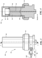
- Figure 4 schematically shows a cross-sectional view of the fixture 38 of Figure 3 along section line 4-4.
- Figure 5 schematically shows a cross-sectional, perspective view of the fixture 38 of Figure 3 across a section plane that is generally orthogonal to the section plane shown in Figure 4 .
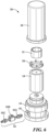
- Figure 6 schematically shows a perspective, exploded view of the fixture 38 shown in Figure 3 .
- the body 42 is made up generally of two interlocking housing components-namely, a base housing 44 having a port for receiving a gas, and a corresponding chamber housing 46 that locks onto the base housing 44 and forms a chamber 43 containing the gas and the object 10.
- the housings 44 and 46 may lock together either with a snap-fit connection, or a threaded connection using a double helix thread pattern.
- the chamber housing 46 should have minimal x-ray attenuation qualities, while the base does not necessarily have such a requirement.
- the chamber housing 46 or at least the top portion of the chamber 43, is substantially transparent to x-rays.
- the chamber housing 46 also preferably has a high-pressure relief valve (not shown) in case the pressure exceeds some prescribed upper limit (e.g., 35 atmospheres or 75 atmospheres).
- some prescribed upper limit e.g. 35 atmospheres or 75 atmospheres.
- the fixture 38 has an O-ring 48 between the top, outer dimension of the base housing 44 and the bottom, inner dimension of the chamber housing 46.
- the housing has a valve mechanism 50 coupled with the housing inlet 40, and a gas channel 52 that directs the gas through the interior of the fixture 38 and into the chamber 43.
- the fixture 38 also includes a riser member (“riser 54") that forms at least a portion of that gas channel 52.
- the riser 54 also has another function - controlling the gas volume of the chamber 43 by displacement. Specifically, the volume of gas used can have a significant impact on the cost of the process. The inventors discovered that they could minimize the amount of gas used in the process by permitting the least amount of chamber volume for a given use.
- the housings 44 and 46 and fixture 38 may be distributed and used as a kit with a plurality of different risers 54 for each fixture 38.
- Each riser 54 thus may have a different height and used depending on the size of the object 10 being imaged. For example, if the object 10 has a height of 12.7 cm (5 inches), then the system 16 may incorporate a riser 54 that permits a clearance of 15.24 cm (6 inches) from the top of the chamber 43. Alternatively, as another example, if the object 10 has a height of 5.08 cm (2 inches), then the system 16 may incorporate a riser 54 that permits a clearance of 6.35 cm (2.5 inches) or 7.62 cm (3 inches) from the top of the chamber 43.
- the riser 54 is formed from plastic or other similar low attenuation material. Other embodiments may use other materials.
- the riser 54 or set of risers 54, are optional components. Instead, various embodiments simply may position the object 10 within the chamber 43 without the riser 54 at all.
- the size of the chamber 43 thus may be configured to image a specific item or set of items having a maximum height.
- the housings 44 and 46 can be distributed in various sizes (in height, width, and/or shape), either with or without the risers 54, to accommodate different types of devices/objects 10.
- Some embodiments secure a positioning ring/member 56 on the top surface of the riser 54 to precisely position the object 10. Again, as with the housings 44 and 46, the positioning ring 56 should have a substantially low attenuation impact on x-rays.
- the inlet 40 to the gas channel 52 preferably has a valving mechanism that normally seals the interior of the chamber 43 when in the closed position.
- Figures 3 , 5 , and 6 show one type of valving mechanism that can accomplish the required functions.
- the value mechanism has an inlet fitting 50A for sealingly connecting with the gas inlet 40 of the base housing 44, a ball valve 50B coupled with the fitting to control gas flow, and an external quick connect/disconnect fitting 50C for connecting with a tube or hose from a gas source.
- the valving mechanism described in the figures is for illustrative purposes only.
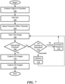
- Figure 7 shows a process of imaging a heterogeneous object 10 in accordance with illustrative embodiments of the invention.
- This process is a simplified version of what could be a much longer process. Accordingly, the process may entail additional steps that are not discussed in Figure 7 . Moreover, some embodiments may perform various steps in a different order than that described. Those skilled in the art should be able to make appropriate changes to the order and number of steps in the process, and still meet the spirit of various embodiments.
- step 700 positions the object 10 in the chamber 43.
- an operator or technician manually separates the chamber housing 46 from the base housing 44, and places the object 10 (e.g., a stent) on the positioning ring 56.
- the operator reconnects the chamber housing 46 to the base housing 44.
- the O-ring 48 which is squeezed between the base housing 44 and the chamber housing 46, ensures that the chamber 43 is substantially sealed for the intended gasses being used.
- the process adds an appropriate gas through the valve mechanism 50 to the chamber 43.
- the technician can connect a hose from a gas source to the quick connect fitting 50C of the valve mechanism 50.
- the valve mechanism 50 then may be opened to permit a prescribed amount of gas into the interior chamber 43.
- the amount of gas depends upon the materials making up the object 10, the size of the chamber 43, and the type of gas being used.
- the technician closes the valve mechanism 50 and removes the hose from the fitting.
- Alternative embodiments may keep the gas line connected to the quick connect fitting 50C.
- this may be the case when used with CT machines that rotate around the object 10 being imaged.
- the base housing 44 of the fixture 38 may have an annular bearing or rotatable part that rotates freely relative to the chamber housing 46.
- the gas should have no substantial effect on the object 10.
- the gas should not damage or oxidize the object 10.
- the gas should have a relatively high density capable of attenuating x-rays, particularly when subjected to appropriate pressures.
- the gas is an inert gas, such as a noble gas.
- the gas preferably is a pure gas or mixture having one or more of xenon, argon, and krypton.
- the gas can include components of all three gases, along with other gases.
- the gas can be a substantially pure gas, such as substantially pure xenon. Some embodiments may use other gases, depending upon the application.
- step 704 adjusts/increases the pressure within the chamber 43.
- This increased gas density ideally increases the gas density to a point where it sufficiently attenuates x-rays to provide meaningful contrast between it and the low attenuating material portion of the object 10.
- the gas is dense enough to provide a contrasting boundary (with the low attenuating portion of the object 10) that is readily visible on the ultimately formed two-dimensional images/projections. As such, that boundary should have substantially accurate topological and structural details at least of the low attenuating portions of the object 10.
- the technician increases the pressure using conventional methods (e.g., connecting the valve mechanism 50 to a positive pressure source), which, as mentioned, correspondingly increases the density of the gas.
- the amount of the increase in pressure at this step can be based upon empirical data of prior use. Alternatively, the amount of increased pressure can be relatively arbitrary, and will be checked and adjusted in subsequent steps (steps 706 -714) to ensure proper calibration.
- the amount of pressure depends upon the gas being used. For example, increasing the pressure up to about 27-29 atmospheres should provide satisfactory attenuation when using xenon. Other gases, however, may require higher or lower pressures greater than about 1 atmosphere. Of course, the fixture 38 must be configured to withstand such high pressures.
- the pressure may or may not be sufficient enough to provide adequate contrast for capturing details of the low attenuating portion of the object 10. If not, then the system 16 may be tuned to have appropriate contrasts.
- the process thus continues to step 706, which takes a "test image" of the object 10-to determine if the contrast is appropriate.
- the x-ray source 22 thus transmits penetrating x-rays toward the object 10.
- the voltage or intensity of the x-rays should be commensurate with the amount to appropriately image the higher attenuating portion of the object 10. For example, with a stent, the voltage should be sufficient to image the metal mesh 12. Of course, this higher energy prevents the polymer substrate 14 from attenuating enough of the x-rays to produce meaningful image data.
- the high density, pressurized gas solves this problem.
- Step 708 thus determines if there is an appropriate amount of contrast between the pressurized gas and the low attenuation portion of the object 10.
- the low attenuation portions of the object 10 may be substantially clear and have a defined, visually perceptible boundary between it and the darker gas.
- the CT machine 18 transmits the raw data to the computer, which generates a two dimensional image of the object 10.
- the two-dimensional test image may be displayed on the display device 32 of the computer system 20, or printed out as a hard copy for review by the technician.
- the technician reviews the test image at step 708 to determine if there is enough contrast between the gas and the low attenuation portions of the object 10.
- the test image is a grey-scale image having varying degrees of grey, from white to black. Knowing how the object 10 should look, the technician reviews the contrasting grey scale/shades at the appropriate boundary regions of the test image. Again, as noted above, the pressurized gas should be noticeably darker, in grey scale, than the generally clear or light images of the low attenuation portion of the object 10.
- the size of the pixels, as well as their pitch, may impact the necessary contrast level.
- a monitor with many pixels that are all very small and closely spaced together may have better contrast than monitors having larger pixels that are spaced farther apart.
- the display device magnification level of the image also can impact the contrast.
- the bit length of a monitor or detector can lead to improved or reduced contrast.
- the technician typically should be looking for relatively clearly defined boundaries between the gas and the lower attenuation portions of the object 10.
- the amount of contrast can be qualitatively and/or quantitatively defined. After the appropriate contrast is determined, many like objects may be imaged without repeating these same calibration steps.
- step 712 which increases the pressure within the chamber 43.
- the amount of the increase may be qualitatively or quantitatively defined.
- the technician may be directed to increase the pressure by no more than a fixed amount for each iteration.
- the technician may increase the pressure an amount that is commensurate to the perceived lack of contrast.
- Either case i.e., a fixed increase or other type of increase
- this adjustment of pressure within the sealed chamber 43 is considered to be made has a function of the density of the low attenuation portion of the object 10.
- the technician may reduce the pressure in a conventional manner to bring the contrast back to a more appropriate state.
- the technician may simply open the valve mechanism 50 to relieve some of the pressure.
- step 706 the process loops back to step 706, which takes another test image and again determines if the contrast is appropriate. If the contrast is appropriate, then the process continues to step 716, which captures a plurality of different two-dimensional images of the object 10.
- the CT machine 18 may take between 1000 and 2000 different two-dimensional images of the object 10 from all sides (i.e., about the entire 360 degree periphery of the object 10). Accordingly, to produce a plurality of different two dimensional images, the CT machine 18 rotates the object 10, relative to the x-ray source 22, which directs penetrating x-rays in a cone-like pattern toward and through the fixture 38 and object 10.
- illustrative embodiments rotate the rotary table 28 while generating the two-dimensional images, thus rotating the object 10 about its longitudinal axis.
- Conventional processes such as program code executing on the computer, then may produce a three-dimensional image from the plurality of two-dimensional images (step 718). Although they may not necessarily be displayed on the display device 32 as the exact same size of the object 10, the three-dimensional images should be substantially representative of the actual topology and dimensions of the object 10. Accordingly, conventional measurement technology software may measure the three dimensional image to ascertain specific features and qualities of the object 10 itself.
- the pressurized gas thus may be considered to form a "mold,” “negative,” or “shadow” of at least the outside surface of the object 10 being measured.
- the low attenuating portions may be reconstructed using its boundary with the gas.
- the high attenuation portions are readily visible on the image with or without the gas.
- computer program code or other processes may color the low attenuation portions bounded by the gas. Such processes may be manual (e.g., performed by a technician) or automatic. This should highlight the low attenuation portions more clearly, enabling a user to better see and view the topological details.
- program code executing on the computer 34 may calculate whether, at step 708, there is an appropriate contrast between the low attenuation portion of the object 10 and the pressurized gas.
- the computer thus may have certain prescribed numerical thresholds to compare against to determine the desired contrast.
- the system 16 may repeatedly change the pressure until the contrasting shades, at the appropriate locations, are at least equal to or greater than a prescribed numerical value representing the difference between the shades.
- the gas may be added, and/ or the pressure may be adjusted, using some automated means.
- embodiments of the invention may be implemented at least in part in any conventional computer programming language. For example, some embodiments may be implemented in a procedural programming language (e.g., "C"), or in an object oriented programming language (e.g., "C++"). Other embodiments of the invention may be implemented as preprogrammed hardware elements (e.g., application specific integrated circuits, FPGAs, and digital signal processors), or other related components.
- C procedural programming language
- object oriented programming language e.g., "C++”
- preprogrammed hardware elements e.g., application specific integrated circuits, FPGAs, and digital signal processors
- the disclosed apparatus and methods may be implemented at least in part as a computer program product for use with a computer system.
- Such implementation may include a series of computer instructions fixed either on a tangible medium, such as a computer readable medium (e.g., a diskette, CD-ROM, ROM, or fixed disk).
- the series of computer instructions can embody all or part of the functionality previously described herein with respect to the system.
- Such computer instructions can be written in a number of programming languages for use with many computer architectures or operating systems.
- such instructions may be stored in any memory device, such as semiconductor, magnetic, optical or other memory devices, and may be transmitted using any communications technology, such as optical, infrared, microwave, or other transmission technologies.
- such a computer program product may be distributed as a removable medium with accompanying printed or electronic documentation (e.g., shrink wrapped software), preloaded with a computer system (e.g., on system ROM or fixed disk), or distributed from a server or other remove device over the network (e.g., the Internet or World Wide Web).
- a computer system e.g., on system ROM or fixed disk
- a server or other remove device e.g., the Internet or World Wide Web
- some embodiments of the invention may be implemented as a combination of both software (e.g., a computer program product) and hardware.
Landscapes
- Health & Medical Sciences (AREA)
- Engineering & Computer Science (AREA)
- Nuclear Medicine, Radiotherapy & Molecular Imaging (AREA)
- Pulmonology (AREA)
- Radiology & Medical Imaging (AREA)
- Theoretical Computer Science (AREA)
- Physics & Mathematics (AREA)
- Life Sciences & Earth Sciences (AREA)
- Chemical & Material Sciences (AREA)
- Analytical Chemistry (AREA)
- Biochemistry (AREA)
- General Health & Medical Sciences (AREA)
- General Physics & Mathematics (AREA)
- Immunology (AREA)
- Pathology (AREA)
- Analysing Materials By The Use Of Radiation (AREA)
Description
- The invention generally relates to generating images of objects and, more particularly, the invention relates to generating detailed images of heterogeneous objects.
- Coordinate measuring machines (CMMs) are the gold standard for accurately measuring a wide variety of work pieces. For example, CMMs can measure critical dimensions of aircraft engine components, surgical tools, and gun barrels. Precise and accurate measurements help ensure that their underlying systems, such as an aircraft in the case of aircraft components, operate as specified.
- Recently, those in the art have begun using computed tomography (CT) systems as CMMs for coordinate metrology. As known by those in the art, a CT system generates three-dimensional images of an object as a function of the attenuation of its x-rays by the object. Some materials, such as metal, may attenuate x-rays sufficiently under typical x-ray power settings, to generate an appropriate image. Other materials, however (e.g., polymers), may not sufficiently attenuate x-rays at the same or similar power settings.
- This creates problems for heterogeneous objects. More specifically, CT imaging techniques known to the inventors do not adequately image objects made from heterogeneous materials in a way that is non-invasive or nondestructive. For example, those techniques cannot adequately image a stent, which is made from a metal mesh frame supporting one or more polymers.
- An example of X-ray micro-tomographic inspection of stents is disclosed in Connolley et al., "X-ray micro-tomography of a coronary stent deployed in a model artery", Medical Engineering & Physics, Vol. 29 (2007) 1132-1141.
- Although the metal mesh should adequately attenuate the x-rays, the polymer typically does not. Accordingly, rather than producing an image of the entire stent, the noted techniques may produce an image of the metal mesh without the polymers. Indeed, such an image does not have enough information to measure many of its important features, such as those features formed from polymers.
- In accordance with the present invention, a method of imaging a heterogeneous object positions the heterogeneous object within a fixture having a chamber. The heterogeneous object has a first portion and a second portion, where the first portion has the property of attenuating x-rays more than the second portion. After the object is in the chamber, the method adds an inert gas to the chamber, seals the chamber to substantially contain the gas within the chamber, and increases the pressure within the sealed chamber as a function of the density of the second portion of the object. The gas may include one or more of the xenon, argon, and krypton. The density of the gas increases with the increased pressure within the sealed chamber, thus producing the contrast. The method also penetrates the object with x-rays to produce a plurality of images of the object. The pressurized gas contrasts with the second portion of the object in at least some of the plurality of images to form a contrasting boundary, said boundary having topological details at least of the second portion of the object. After directing x-rays toward the object, the method generates a three-dimensional representation of the object using (at least) the contrast produced by the pressurized gas in the plurality of images, the three-dimensional representation showing the topological details of the object.
- Among others, the gas may be a noble gas, such as xenon. As such, the gas should not cause a destructive reaction with the object. The x-rays may be directed from a CT machine generating the x-rays. To obtain a three-dimensional view of the object, the method also may rotate the chamber to produce the plurality of images.
- The pressure may range from any of a number of pressures, such as from about 1 atmosphere to about 50 atmospheres. Moreover, when changing the pressure within the sealed chamber, the method may generate at least one test image of the object at a first pressure, and then change the pressure within the chamber as a function of the contrast between the second portion and the gas as shown in the test image. In accordance with the present invention, the three-dimensional representation of the object shows the topological object details, thus enabling measurement of at least one of the topological object details of the contrasting boundary.
- In accordance with another example outside the scope of the present invention, a method of imaging a heterogeneous object positions a heterogeneous object within a fixture having a chamber. The fixture also has a valve for receiving a gas and normally sealing the chamber. Thus, the object is within the chamber. Next the method positions the fixture within an active region of a CT machine, fluidly connects a gas line to the valve, and injects an inert gas into the chamber through the gas line and the valve. The inert gas may include one or more of the xenon, argon, and krypton. The method then increases the pressure within the sealed chamber to increase the density of the gas within the chamber, and directs x-ray energy toward the active region of the CT machine to produce a plurality of two-dimensional images of the object and the pressurized gas. Finally, the method generates a three-dimensional representation of the object from the plurality of images.
- In accordance with the present invention, a system for imaging a heterogeneous object has a fixture with 1) a chamber for receiving an object, and 2) a valve for receiving a gas and normally sealing the chamber. The system also has a mechanism for adding inert gas into the chamber through the valve, and a mechanism for increasing the pressure within the sealed chamber to increase the density of the gas within the chamber. In addition, the system further has a mechanism for directing x-ray energy toward the fixture to produce a plurality of images of the object and the pressurized gas. The plurality of images show the pressurized gas and object as having contrasting shades that form a contrasting boundary having topological details of at least the second portion of the object. Finally, the system has a mechanism for generating a three-dimensional representation of the object using the contrast produced by the pressurized gas in the plurality of images and for measuring at least one of the topological details of the contrasting boundary using the three-dimensional representation of the object.
- Illustrative embodiments of the invention are implemented as a computer program product having a computer usable medium with computer readable program code thereon. The computer readable code may be read and utilized by a computer system in accordance with conventional processes.
- Those skilled in the art should more fully appreciate advantages of various embodiments of the invention from the following "Description of Illustrative Embodiments," discussed with reference to the drawings summarized immediately below.
-
Figure 1 schematically shows a heterogeneous object that may be imaged in accordance with illustrative embodiments of the invention. -
Figure 2 schematically shows a system for imaging a heterogeneous object, such as the heterogeneous object ofFigure 1 , in accordance with illustrative embodiments of the invention. -
Figure 3 schematically shows a side view of an imaging fixture for imaging a heterogeneous object in accordance with illustrative embodiments of the invention. -
Figure 4 schematically shows a cross-sectional view of the fixture ofFigure 3 along section line 4-4. -
Figure 5 schematically shows a cross-sectional, perspective view of the fixture ofFigure 3 across a section plane that is generally orthogonal to the section plane shown inFigure 4 . -
Figure 6 schematically shows a perspective, exploded view of the fixture shown inFigure 3 . -
Figure 7 shows a method of using the system ofFigure 2 to image a heterogeneous object in accordance with illustrative embodiments of the invention. - In illustrative embodiments, an x-ray imaging system captures low density/attenuation portions of a heterogeneous object that normally are invisible to x-rays. In fact, the system can capture that image without damaging or substantially altering any portion of that object. To that end, the system seals the heterogeneous object within the gas filled chamber of a fixture. The pressure within the chamber is set, and the gas is selected, to provide sufficient image contrast between the low attenuation portions of the object and the pressurized gas. The pressurized gas forms a boundary with the low attenuation portions of the object, consequently causing it (the gas) to have a boundary topology that is substantially identical to the portion of the object it bounds.
- Using this technique, the x-ray system captures a plurality of two-dimensional images of the pressurized gas and the object, visually detailing the topology, size, and shape of the low attenuation portions of the object. Of course, the x-ray system also captures the high attenuation portions of the object in those same images. These two-dimensional images subsequently can be converted into a dimensionally and structurally accurate three-dimensional representation of the actual object. Accordingly, conventional metrology techniques may accurately measure the dimensions of the object without having to make contact with it. Details of illustrative embodiments are discussed below.
-
Figure 1 schematically shows aheterogeneous object 10 that may be imaged in accordance with illustrative embodiments of the invention. Specifically, theobject 10 shown inFigure 1 is a conventional stent, which is intended to be surgically implanted within a damaged artery. For example, a cardiologist may implant a stent into an artery of a patient after removing arterial plaque that caused a heart attack. Accordingly, the physical makeup and composition of the stent can be the difference between life and death. Stated another way, inaccurate dimensions or ill-defined structures can have catastrophic effects to the patient. - As known by those skilled in the art, a stent is a tubular device commonly having a flexible metal skeleton or
mesh 12 that supports a fabric orpolymeric substrate 14. Among other things, thesubstrate 14 may include medication or other substances intended to ensure that the patient's artery does not become blocked again. To check its dimensions, to the inventors' knowledge, those skilled in the art manually inspect the stents under a microscope. Such a process is time-consuming and inherently inaccurate. - Use of a current, state-of-the-art computed tomography system 16 ("
CT systems 16,Figure 2 ") also is not feasible because the polymeric or fabric portion of the stent is invisible to x-rays. In other words, the polymeric (or fabric) portion of the stent does not adequately attenuate x-rays to produce a complete image-it lacks sufficient contrast to the surrounding air. Accordingly, a conventional x-ray image of a stent undesirably shows themetal mesh 12 only. Such an image is not adequate for precisely measuring the dimensions of the stent. The inventors solved this problem by using x-ray imaging techniques for imaging a stent/object 10 that is engulfed or encapsulated by a high density inert gas under pressure. Such a technique nondestructively and accurately images fine details of the stent. - It should be noted that discussion of the stent is for illustrative purposes only. Other
heterogeneous objects 10 similarly benefit from the systems and methods described herein. For example, illustrative embodiments can apply to a wide variety of different devices, such as artificial heart valves, drug delivery devices, coated tubes, electronic devices, other medical devices, coatings on microelectronics, consumer packaging, insulated wires, and a wide variety ofother objects 10. Accordingly, discussion of a stent or otherheterogeneous object 10 is not intended to limit all embodiments of the invention. -
Figure 2 schematically shows asystem 16 that can image aheterogeneous object 10 in accordance with illustrative embodiments of the invention. As shown, thesystem 16 includes a conventional computed tomography machine ("CT machine 18") coordinated and controlled by an accompanyingcomputer system 20. TheCT machine 18 is shown in a cut-away view the detail some of its interior components. Specifically, like other CT machines, theCT machine 18 in this figure has anx-ray source 22 that transmits x-rays (typically) in a generally cone-shaped pattern (a/k/a a "cone beam"), toward and through anobject 10 within its interior region. This interior region, which contains theobject 10 being imaged as it is receiving x-rays, is referred to herein as an "active region 24." As known by those skilled in the art, theobject 10 attenuates the x-rays to some degree, changing the pattern of x-rays on the opposite side of theobject 10. Adetector 26 on the opposite side of theobject 10 detects this pattern, producing a two-dimensional representation/image of theobject 10. - To obtain a three-dimensional representation/image, however, the
system 16 moves the position of theobject 10 relative to thex-ray source 22 anddetector 26. Some CT machines rotate thex-ray source 22 anddetector 26 while leaving theobject 10 stationary. Other CT machines, such as that shown inFigure 2 , rotate theobject 10, but keep thex-ray source 22 anddetector 26 stationary. Of course, various embodiments may use either type of arrangement. In the latter case, theobject 10 may be positioned on a rotating device, such as the platter of a rotary table 28. Among other ways, the rotary table 28 may be configured to precisely rotate the object 10 a predefined amount each time it generates a two-dimensional image. For example, theCT machine 18 may take 1000 to 2000 two-dimensional images of theobject 10 on the platter. These two-dimensional images, which are taken from slightly different perspectives, often are referred to in the art as "projections." - Conventional software techniques convert this plurality of two-dimensional images/projections into a detailed, comprehensive three-dimensional representation of the
object 10. For example, thecomputer system 20, which has adisplay device 32, a CPU/memory/logic within a chassis 34 (i.e., a computer),input device 36, and other conventional components, may execute these conventional software routines to generate a three-dimensional representation of theobject 10. - Rather than place it directly on the rotary table 28, illustrative embodiments position the
object 10 to be scanned/imaged within a gas filled, sealedfixture 38 that is removable from the interior of theCT machine 18. Thefixture 38, with theobject 10 in its interior, thus is positioned on the rotary table 28. - More specifically,
Figure 3 shows a perspective view of thefixture 38 configured in accordance with illustrative embodiments of the invention. As shown, thefixture 38 has aninlet 40 for receiving a gas, and abody 42 forming an interior chamber 43 (Figures 4-5 , discussed below) for receiving and containing both theobject 10 and a pressurized gas. Indeed, to facilitate imaging, the portion of thefixture 38 containing theobject 10 should be formed primarily from a low density material that does not substantially attenuate x-rays. Among other things, thefixture 38 can have a cylindrical shape (or other shape) and be formed from a carbon fiber, or a polymeric or plastic material, such as polyvinyl chlorate or nylon. As discussed below, another important quality of thefixture 38 is its capability of sealing specific pressurized gasses within its interior (discussed below) while remaining substantially transparent to x-rays. Those skilled in the art can select the appropriate materials to provide both functions. -
Figures 4-6 schematically show more details of thefixture 38 in accordance with illustrative embodiments of the invention. Specifically,Figure 4 schematically shows a cross-sectional view of thefixture 38 ofFigure 3 along section line 4-4., whileFigure 5 schematically shows a cross-sectional, perspective view of thefixture 38 ofFigure 3 across a section plane that is generally orthogonal to the section plane shown inFigure 4 . For further detail,Figure 6 schematically shows a perspective, exploded view of thefixture 38 shown inFigure 3 . - As shown, the
body 42 is made up generally of two interlocking housing components-namely, abase housing 44 having a port for receiving a gas, and acorresponding chamber housing 46 that locks onto thebase housing 44 and forms achamber 43 containing the gas and theobject 10. Among other ways, thehousings - The
chamber housing 46 should have minimal x-ray attenuation qualities, while the base does not necessarily have such a requirement. In preferred embodiments, thechamber housing 46, or at least the top portion of thechamber 43, is substantially transparent to x-rays. Thechamber housing 46 also preferably has a high-pressure relief valve (not shown) in case the pressure exceeds some prescribed upper limit (e.g., 35 atmospheres or 75 atmospheres). To make a sealed connection between thehousings fixture 38 has an O-ring 48 between the top, outer dimension of thebase housing 44 and the bottom, inner dimension of thechamber housing 46. - As best shown in
Figure 5 , the housing has avalve mechanism 50 coupled with thehousing inlet 40, and agas channel 52 that directs the gas through the interior of thefixture 38 and into thechamber 43. Thefixture 38 also includes a riser member ("riser 54") that forms at least a portion of thatgas channel 52. Theriser 54 also has another function - controlling the gas volume of thechamber 43 by displacement. Specifically, the volume of gas used can have a significant impact on the cost of the process. The inventors discovered that they could minimize the amount of gas used in the process by permitting the least amount of chamber volume for a given use. - To that end, the
housings fixture 38 may be distributed and used as a kit with a plurality ofdifferent risers 54 for eachfixture 38. Eachriser 54 thus may have a different height and used depending on the size of theobject 10 being imaged. For example, if theobject 10 has a height of 12.7 cm (5 inches), then thesystem 16 may incorporate ariser 54 that permits a clearance of 15.24 cm (6 inches) from the top of thechamber 43. Alternatively, as another example, if theobject 10 has a height of 5.08 cm (2 inches), then thesystem 16 may incorporate ariser 54 that permits a clearance of 6.35 cm (2.5 inches) or 7.62 cm (3 inches) from the top of thechamber 43. In illustrative embodiments, theriser 54 is formed from plastic or other similar low attenuation material. Other embodiments may use other materials. - It should be noted that the
riser 54, or set ofrisers 54, are optional components. Instead, various embodiments simply may position theobject 10 within thechamber 43 without theriser 54 at all. The size of thechamber 43 thus may be configured to image a specific item or set of items having a maximum height. In fact, thehousings risers 54, to accommodate different types of devices/objects 10. - Some embodiments secure a positioning ring/
member 56 on the top surface of theriser 54 to precisely position theobject 10. Again, as with thehousings positioning ring 56 should have a substantially low attenuation impact on x-rays. - As noted above, the
inlet 40 to thegas channel 52 preferably has a valving mechanism that normally seals the interior of thechamber 43 when in the closed position.Figures 3 ,5 , and6 show one type of valving mechanism that can accomplish the required functions. To that end, the value mechanism has an inlet fitting 50A for sealingly connecting with thegas inlet 40 of thebase housing 44, aball valve 50B coupled with the fitting to control gas flow, and an external quick connect/disconnect fitting 50C for connecting with a tube or hose from a gas source. Of course, those skilled in the art can use other valving mechanisms and thus, the valving mechanism described in the figures is for illustrative purposes only. -
Figure 7 shows a process of imaging aheterogeneous object 10 in accordance with illustrative embodiments of the invention. This process is a simplified version of what could be a much longer process. Accordingly, the process may entail additional steps that are not discussed inFigure 7 . Moreover, some embodiments may perform various steps in a different order than that described. Those skilled in the art should be able to make appropriate changes to the order and number of steps in the process, and still meet the spirit of various embodiments. - The process begins at
step 700, which positions theobject 10 in thechamber 43. To that end, an operator or technician manually separates thechamber housing 46 from thebase housing 44, and places the object 10 (e.g., a stent) on thepositioning ring 56. The operator then reconnects thechamber housing 46 to thebase housing 44. As noted, the O-ring 48, which is squeezed between thebase housing 44 and thechamber housing 46, ensures that thechamber 43 is substantially sealed for the intended gasses being used. - Next, at
step 702, the process adds an appropriate gas through thevalve mechanism 50 to thechamber 43. To that end, the technician can connect a hose from a gas source to the quick connect fitting 50C of thevalve mechanism 50. Thevalve mechanism 50 then may be opened to permit a prescribed amount of gas into theinterior chamber 43. Among other things, the amount of gas depends upon the materials making up theobject 10, the size of thechamber 43, and the type of gas being used. After filling thechamber 43 to the appropriate level, the technician closes thevalve mechanism 50 and removes the hose from the fitting. - Alternative embodiments may keep the gas line connected to the quick connect fitting 50C. For example, this may be the case when used with CT machines that rotate around the
object 10 being imaged. As a second example, thebase housing 44 of thefixture 38 may have an annular bearing or rotatable part that rotates freely relative to thechamber housing 46. - As noted above, the gas should have no substantial effect on the
object 10. For example, the gas should not damage or oxidize theobject 10. Moreover, to appropriately attenuate x-rays, the gas should have a relatively high density capable of attenuating x-rays, particularly when subjected to appropriate pressures. In illustrative embodiments, the gas is an inert gas, such as a noble gas. More specifically, the gas preferably is a pure gas or mixture having one or more of xenon, argon, and krypton. For example, the gas can include components of all three gases, along with other gases. As another example, the gas can be a substantially pure gas, such as substantially pure xenon. Some embodiments may use other gases, depending upon the application. - The process continues to step 704, which adjusts/increases the pressure within the
chamber 43. This increased gas density ideally increases the gas density to a point where it sufficiently attenuates x-rays to provide meaningful contrast between it and the low attenuating material portion of theobject 10. In preferred embodiments, the gas is dense enough to provide a contrasting boundary (with the low attenuating portion of the object 10) that is readily visible on the ultimately formed two-dimensional images/projections. As such, that boundary should have substantially accurate topological and structural details at least of the low attenuating portions of theobject 10. - To those ends, the technician increases the pressure using conventional methods (e.g., connecting the
valve mechanism 50 to a positive pressure source), which, as mentioned, correspondingly increases the density of the gas. The amount of the increase in pressure at this step can be based upon empirical data of prior use. Alternatively, the amount of increased pressure can be relatively arbitrary, and will be checked and adjusted in subsequent steps (steps 706 -714) to ensure proper calibration. - The amount of pressure depends upon the gas being used. For example, increasing the pressure up to about 27-29 atmospheres should provide satisfactory attenuation when using xenon. Other gases, however, may require higher or lower pressures greater than about 1 atmosphere. Of course, the
fixture 38 must be configured to withstand such high pressures. - At this point, the pressure may or may not be sufficient enough to provide adequate contrast for capturing details of the low attenuating portion of the
object 10. If not, then thesystem 16 may be tuned to have appropriate contrasts. The process thus continues to step 706, which takes a "test image" of the object 10-to determine if the contrast is appropriate. Thex-ray source 22 thus transmits penetrating x-rays toward theobject 10. The voltage or intensity of the x-rays should be commensurate with the amount to appropriately image the higher attenuating portion of theobject 10. For example, with a stent, the voltage should be sufficient to image themetal mesh 12. Of course, this higher energy prevents thepolymer substrate 14 from attenuating enough of the x-rays to produce meaningful image data. The high density, pressurized gas solves this problem. - Step 708 thus determines if there is an appropriate amount of contrast between the pressurized gas and the low attenuation portion of the
object 10. For example, when viewing the test image, the low attenuation portions of theobject 10 may be substantially clear and have a defined, visually perceptible boundary between it and the darker gas. - To that end, after passing x-rays through the
fixture 38 andobject 10, theCT machine 18 transmits the raw data to the computer, which generates a two dimensional image of theobject 10. The two-dimensional test image may be displayed on thedisplay device 32 of thecomputer system 20, or printed out as a hard copy for review by the technician. Accordingly, the technician reviews the test image atstep 708 to determine if there is enough contrast between the gas and the low attenuation portions of theobject 10. In illustrative embodiments, the test image is a grey-scale image having varying degrees of grey, from white to black. Knowing how theobject 10 should look, the technician reviews the contrasting grey scale/shades at the appropriate boundary regions of the test image. Again, as noted above, the pressurized gas should be noticeably darker, in grey scale, than the generally clear or light images of the low attenuation portion of theobject 10. - A number of factors contribute to determining whether the contrast is sufficient enough. Among other things, the size of the pixels, as well as their pitch, may impact the necessary contrast level. For example, a monitor with many pixels that are all very small and closely spaced together may have better contrast than monitors having larger pixels that are spaced farther apart. In addition, the display device magnification level of the image also can impact the contrast. Furthermore, the bit length of a monitor or detector can lead to improved or reduced contrast. Ultimately, the technician typically should be looking for relatively clearly defined boundaries between the gas and the lower attenuation portions of the
object 10. The amount of contrast can be qualitatively and/or quantitatively defined. After the appropriate contrast is determined, many like objects may be imaged without repeating these same calibration steps. - Accordingly, if there is not enough contrast, the process moves to step 712, which increases the pressure within the
chamber 43. This should further increase the density of the gas. The amount of the increase may be qualitatively or quantitatively defined. For example, the technician may be directed to increase the pressure by no more than a fixed amount for each iteration. Alternatively, the technician may increase the pressure an amount that is commensurate to the perceived lack of contrast. Either case (i.e., a fixed increase or other type of increase), however, may be considered to be an increase in the pressure as a function of the lack of sufficient contrast. In other words, this adjustment of pressure within the sealedchamber 43 is considered to be made has a function of the density of the low attenuation portion of theobject 10. - There may be instances, however, where the contrast is inappropriate because the gas is too dense. This may be considered to be a "saturated" state. Accordingly, the technician may reduce the pressure in a conventional manner to bring the contrast back to a more appropriate state. Among other ways, the technician may simply open the
valve mechanism 50 to relieve some of the pressure. - After increasing or decreasing the pressure within the
chamber 43, the process loops back to step 706, which takes another test image and again determines if the contrast is appropriate. If the contrast is appropriate, then the process continues to step 716, which captures a plurality of different two-dimensional images of theobject 10. For example, as discussed above, theCT machine 18 may take between 1000 and 2000 different two-dimensional images of theobject 10 from all sides (i.e., about the entire 360 degree periphery of the object 10). Accordingly, to produce a plurality of different two dimensional images, theCT machine 18 rotates theobject 10, relative to thex-ray source 22, which directs penetrating x-rays in a cone-like pattern toward and through thefixture 38 andobject 10. Using thesystem 16 ofFigure 2 , illustrative embodiments rotate the rotary table 28 while generating the two-dimensional images, thus rotating theobject 10 about its longitudinal axis. - Conventional processes, such as program code executing on the computer, then may produce a three-dimensional image from the plurality of two-dimensional images (step 718). Although they may not necessarily be displayed on the
display device 32 as the exact same size of theobject 10, the three-dimensional images should be substantially representative of the actual topology and dimensions of theobject 10. Accordingly, conventional measurement technology software may measure the three dimensional image to ascertain specific features and qualities of theobject 10 itself. - The pressurized gas thus may be considered to form a "mold," "negative," or "shadow" of at least the outside surface of the
object 10 being measured. The low attenuating portions may be reconstructed using its boundary with the gas. Of course, the high attenuation portions are readily visible on the image with or without the gas. Rather than show the low attenuating portions as clear or white, computer program code or other processes may color the low attenuation portions bounded by the gas. Such processes may be manual (e.g., performed by a technician) or automatic. This should highlight the low attenuation portions more clearly, enabling a user to better see and view the topological details. - Some embodiments automate various steps of the process using computer logic. For example, program code executing on the
computer 34 may calculate whether, atstep 708, there is an appropriate contrast between the low attenuation portion of theobject 10 and the pressurized gas. The computer thus may have certain prescribed numerical thresholds to compare against to determine the desired contrast. In that case, thesystem 16 may repeatedly change the pressure until the contrasting shades, at the appropriate locations, are at least equal to or greater than a prescribed numerical value representing the difference between the shades. As another example, the gas may be added, and/ or the pressure may be adjusted, using some automated means. - Various embodiments of the invention may be implemented at least in part in any conventional computer programming language. For example, some embodiments may be implemented in a procedural programming language (e.g., "C"), or in an object oriented programming language (e.g., "C++"). Other embodiments of the invention may be implemented as preprogrammed hardware elements (e.g., application specific integrated circuits, FPGAs, and digital signal processors), or other related components.
- In an alternative embodiment, the disclosed apparatus and methods (e.g., see the various flow charts described above) may be implemented at least in part as a computer program product for use with a computer system. Such implementation may include a series of computer instructions fixed either on a tangible medium, such as a computer readable medium (e.g., a diskette, CD-ROM, ROM, or fixed disk). The series of computer instructions can embody all or part of the functionality previously described herein with respect to the system.
- Those skilled in the art should appreciate that such computer instructions can be written in a number of programming languages for use with many computer architectures or operating systems. Furthermore, such instructions may be stored in any memory device, such as semiconductor, magnetic, optical or other memory devices, and may be transmitted using any communications technology, such as optical, infrared, microwave, or other transmission technologies.
- Among other ways, such a computer program product may be distributed as a removable medium with accompanying printed or electronic documentation (e.g., shrink wrapped software), preloaded with a computer system (e.g., on system ROM or fixed disk), or distributed from a server or other remove device over the network (e.g., the Internet or World Wide Web). Of course, some embodiments of the invention may be implemented as a combination of both software (e.g., a computer program product) and hardware.
Claims (15)
- A method of imaging a heterogeneous object (10) having a first portion and a second portion, the first portion having the property of attenuating x-rays more than the second portion, the method comprising:positioning (700) the heterogeneous object (10) within a fixture (38) having a chamber (43);adding (702) an inert gas to the chamber (43), the inert gas comprising at least one of argon, xenon, and krypton;sealing the chamber (43) to substantially contain the gas within the chamber (43);increasing (704) the pressure within the sealed chamber (43) as a function of the density of the second portion of the object, the density of the gas increasing with the increased pressure within the sealed chamber (43);penetrating x-rays through the object (10) to produce a plurality of images (716) of the object (10), the pressurized gas contrasting with the second portion of the object in at least some of the plurality of images to form a contrasting boundary, said boundary having topological details at least of the second portion of the object;generating (718) a three-dimensional representation of the object (10) using the contrast produced by the pressurized gas in the plurality of images, the three-dimensional representation of the object (10) showing the topological details of the object; andmeasuring at least one of the topological object details of the contrasting boundary using the three-dimensional representation of the object (10).
- The method as defined by claim 1, wherein the gas comprises a mixture of gasses.
- The method as defined by claim 1, wherein the gas includes xenon.
- The method as defined by claim 1, wherein the pressure is greater than 1 atmosphere and less than about 50 atmospheres.
- The method as defined by claim 1, wherein the gas will not cause an oxidation reaction with the object.
- The method as defined by claim 1, further comprising rotating the chamber (43) to produce the plurality of images.
- The method as defined by claim 1, wherein directing the x-rays comprises using a computed tomography machine (18) to generate the x-rays.
- The method as defined by claim 1, wherein changing the pressure within the sealed chamber comprises:generating (706) at least one test image of the object (10) at a first pressure; andchanging the pressure within the chamber (43) as a function of the contrast between the second portion and the gas as shown in the test image.
- A system for imaging a heterogeneous object (10) having topological details and comprising a first portion and a second portion, the first portion having the property of attenuating x-rays more than the second portion, the system comprising:a fixture (38) having a chamber (43) for receiving the heterogeneous object (10), the fixture (38) also having a valve (50) for receiving a gas and normally sealing the chamber (43);means for adding inert gas into the chamber through the valve;means for increasing the pressure within the sealed chamber as a function of the density of the second portion of the object to increase the density of the gas within the chamber;means (22) for directing x-ray energy toward the fixture (38) to produce a plurality of images of the object (10) and the pressurized gas, the plurality of images showing the pressurized gas and object (10) as having contrasting shades that form a contrasting boundary having topological details of at least the second portion of the object;means for generating a three-dimensional representation of the object (10) using the contrast produced by the pressurized gas in the plurality of images, the three-dimensional representation of the object (10) showing the topological details of the object; andmeans for measuring at least one of the topological object details of the contrasting boundary using the three-dimensional representation of the object.
- The system as defined by claim 9, further comprising a display device (32) for displaying the plurality of images of the object (10) and the pressurized gas.
- The system as defined by claim 10, wherein the gas comprises at least one of argon, krypton, and xenon.
- The system as defined by claim 9, wherein the fixture (38) comprises a longitudinal rotational axis.
- The system as defined by claim 12, further comprising means (28) for rotating the fixture about the rotational axis.
- The system as defined by claim 9, further comprising means for determining whether the pressure is to be increased at least a second time.
- The system as defined by claim 9, further comprising a computed tomography machine (18) having an active region to receive the fixture.
Applications Claiming Priority (3)
| Application Number | Priority Date | Filing Date | Title |
|---|---|---|---|
| US13/660,235 US9170215B2 (en) | 2012-10-25 | 2012-10-25 | Apparatus and method of imaging a heterogeneous object |
| PCT/US2013/063702 WO2014066022A1 (en) | 2012-10-25 | 2013-10-07 | Apparatus and method of imaging a heterogeneous object |
| EP13780018.1A EP2912441B1 (en) | 2012-10-25 | 2013-10-07 | Apparatus and method of imaging a heterogeneous object |
Related Parent Applications (2)
| Application Number | Title | Priority Date | Filing Date |
|---|---|---|---|
| EP13780018.1A Division-Into EP2912441B1 (en) | 2012-10-25 | 2013-10-07 | Apparatus and method of imaging a heterogeneous object |
| EP13780018.1A Division EP2912441B1 (en) | 2012-10-25 | 2013-10-07 | Apparatus and method of imaging a heterogeneous object |
Publications (2)
| Publication Number | Publication Date |
|---|---|
| EP3822620A1 EP3822620A1 (en) | 2021-05-19 |
| EP3822620B1 true EP3822620B1 (en) | 2023-09-06 |
Family
ID=49448314
Family Applications (2)
| Application Number | Title | Priority Date | Filing Date |
|---|---|---|---|
| EP20171871.5A Active EP3822620B1 (en) | 2012-10-25 | 2013-10-07 | Apparatus and method of imaging a heterogeneous object |
| EP13780018.1A Active EP2912441B1 (en) | 2012-10-25 | 2013-10-07 | Apparatus and method of imaging a heterogeneous object |
Family Applications After (1)
| Application Number | Title | Priority Date | Filing Date |
|---|---|---|---|
| EP13780018.1A Active EP2912441B1 (en) | 2012-10-25 | 2013-10-07 | Apparatus and method of imaging a heterogeneous object |
Country Status (4)
| Country | Link |
|---|---|
| US (1) | US9170215B2 (en) |
| EP (2) | EP3822620B1 (en) |
| CN (1) | CN104737004B (en) |
| WO (1) | WO2014066022A1 (en) |
Families Citing this family (8)
| Publication number | Priority date | Publication date | Assignee | Title |
|---|---|---|---|---|
| US9678022B2 (en) * | 2014-09-05 | 2017-06-13 | The Boeing Company | Nonaqueous radiopaque fluid and associated imaging system and method |
| US10001446B2 (en) | 2014-11-07 | 2018-06-19 | Ge Energy Oilfield Technology, Inc. | Core sample analysis |
| US9970888B2 (en) | 2014-11-07 | 2018-05-15 | Ge Energy Oilfield Technology, Inc. | System and method for wellsite core sample analysis |
| US20160187313A1 (en) * | 2014-12-31 | 2016-06-30 | Ge Energy Oilfield Technology, Inc. | Core Sample Analysis System with Conditioned Environment |
| US10031148B2 (en) | 2014-12-31 | 2018-07-24 | Ge Energy Oilfield Technology, Inc. | System for handling a core sample |
| US10261204B2 (en) | 2014-12-31 | 2019-04-16 | Ge Energy Oilfield Technology, Inc. | Methods and systems for scan analysis of a core sample |
| DE102016205718A1 (en) * | 2016-04-06 | 2017-10-12 | Siemens Healthcare Gmbh | Method for displaying medical image data |
| KR101888872B1 (en) * | 2018-05-28 | 2018-08-16 | 한국지질자원연구원 | A method for analysis technique of fines migration in sediments with multiphase flow, using x-ray images |
Family Cites Families (18)
| Publication number | Priority date | Publication date | Assignee | Title |
|---|---|---|---|---|
| US3497691A (en) | 1967-06-30 | 1970-02-24 | Ohmart Corp | Dual mode fluorescence and backscatter coating thickness measuring gauge |
| US3843884A (en) | 1971-09-20 | 1974-10-22 | Industrial Nucleonics Corp | X-ray gauging method and apparatus with stabilized response |
| DE2505173A1 (en) | 1975-02-07 | 1976-08-19 | Philips Patentverwaltung | X-RAY ASSEMBLY WITH A GAS-FILLED CHAMBER |
| GB8515552D0 (en) | 1985-06-19 | 1985-07-24 | Boyle Controls Ltd | Coating weight & thickness gauges |
| US4780897A (en) | 1986-05-06 | 1988-10-25 | General Electric Company | Dual energy imaging with kinestatic charge detector |
| US6146657A (en) | 1989-12-22 | 2000-11-14 | Imarx Pharmaceutical Corp. | Gas-filled lipid spheres for use in diagnostic and therapeutic applications |
| US5271401A (en) | 1992-01-15 | 1993-12-21 | Praxair Technology, Inc. | Radiological imaging method |
| DE4342779C1 (en) | 1993-12-15 | 1994-11-17 | Siemens Ag | Gas detector for computer tomography |
| US5545396A (en) | 1994-04-08 | 1996-08-13 | The Research Foundation Of State University Of New York | Magnetic resonance imaging using hyperpolarized noble gases |
| JP3913296B2 (en) | 1996-10-02 | 2007-05-09 | フィルジェン株式会社 | Plasma deposition system |
| JP3668776B2 (en) * | 2002-03-29 | 2005-07-06 | 独立行政法人産業技術総合研究所 | X-ray microscope |
| US6875546B2 (en) * | 2003-03-03 | 2005-04-05 | Freescale Semiconductor, Inc. | Method of patterning photoresist on a wafer using an attenuated phase shift mask |
| US7062012B1 (en) * | 2004-12-09 | 2006-06-13 | Hewlett-Packard Development Company, L.P. | Leak detection of sealed objects using x-ray imaging |
| US7278236B2 (en) * | 2005-03-17 | 2007-10-09 | Phenotype Screening Corporation | Plant root characterization system |
| JP2009539501A (en) | 2006-06-06 | 2009-11-19 | ラトガーズ, ザ ステイト ユニバーシティ オブ ニュー ジャージー | Iodinated polymer |
| AR057580A1 (en) * | 2006-11-14 | 2007-12-05 | Tomografia De Hormigon Armado | METHOD AND PROVISION TO IMPROVE TOMOGRAPHIC DETERMINATIONS THROUGH RADIATIONS, ESPECIALLY APPROPRIATE FOR STEEL BARS IN THE REINFORCED CONCRETE |
| JP2012522589A (en) | 2009-04-01 | 2012-09-27 | ミシェル テクノロジーズ,インコーポレイテッド | Covered stent |
| CN102590242B (en) * | 2012-01-19 | 2013-09-04 | 东南大学 | Method for performing non-destructive detection on evolution of three-dimensional carbonation depth of cement-based material through X-ray scanning |
-
2012
- 2012-10-25 US US13/660,235 patent/US9170215B2/en active Active
-
2013
- 2013-10-07 WO PCT/US2013/063702 patent/WO2014066022A1/en not_active Ceased
- 2013-10-07 EP EP20171871.5A patent/EP3822620B1/en active Active
- 2013-10-07 CN CN201380055466.5A patent/CN104737004B/en active Active
- 2013-10-07 EP EP13780018.1A patent/EP2912441B1/en active Active
Also Published As
| Publication number | Publication date |
|---|---|
| EP2912441B1 (en) | 2020-07-29 |
| US9170215B2 (en) | 2015-10-27 |
| WO2014066022A1 (en) | 2014-05-01 |
| EP3822620A1 (en) | 2021-05-19 |
| US20140119501A1 (en) | 2014-05-01 |
| EP2912441A1 (en) | 2015-09-02 |
| CN104737004B (en) | 2018-06-01 |
| CN104737004A (en) | 2015-06-24 |
Similar Documents
| Publication | Publication Date | Title |
|---|---|---|
| EP2912441B1 (en) | Apparatus and method of imaging a heterogeneous object | |
| CN100551330C (en) | Method for minimizing image artifacts and medical imaging system | |
| JP4330988B2 (en) | X-ray inspection apparatus for reconstructing a three-dimensional data set from a projected image | |
| US9420986B2 (en) | X-ray CT apparatus and X-ray CT image processing method | |
| US9600913B2 (en) | Iterative CT image reconstruction of a ROI with objects outside the scan FoV | |
| EP2336974B1 (en) | Computed tomography method, computer software, computing device and computed tomography system for determining a volumetric representation of a sample | |
| JP3992389B2 (en) | X-ray CT apparatus and phantom | |
| CN107481217A (en) | The space of implantation equipment in object and shape characterization | |
| EP2213235B1 (en) | Method for calibrating a digital x-ray apparatus | |
| JPWO2005011502A1 (en) | Radiation tomography equipment | |
| WO2016158234A1 (en) | Image generation apparatus, image generation method, and x-ray ct apparatus | |
| CN105326524B (en) | The medical imaging procedure and device of the artifact in image can be reduced | |
| JP5060862B2 (en) | Tomography equipment | |
| US8284893B2 (en) | X-ray computer tomography apparatus and image processing apparatus | |
| US8824759B2 (en) | Correcting axial tilt based on object positions in axial slices of three dimensional image | |
| CN108024774A (en) | Spectral Imaging Phantoms and Methods | |
| US6704388B2 (en) | X-ray examination apparatus | |
| WO2002098293A1 (en) | X-ray ct device, image processor, and method for processing image of x-ray ct device | |
| JP4436484B2 (en) | A device that simulates a patient's blood vessels | |
| US20210110597A1 (en) | Systems and methods for visualizing anatomical structures | |
| Sire et al. | X-ray cone beam CT system calibration | |
| US20100303381A1 (en) | Imaging system and imaging method for imaging a region of interest | |
| US11170572B2 (en) | Surface extraction method and apparatus for X-ray CT volume | |
| US10755450B2 (en) | Display of depth location of computed tomography slice images relative to an object to be imaged | |
| JP2007215698A (en) | X-ray ct apparatus |
Legal Events
| Date | Code | Title | Description |
|---|---|---|---|
| PUAI | Public reference made under article 153(3) epc to a published international application that has entered the european phase |
Free format text: ORIGINAL CODE: 0009012 |
|
| STAA | Information on the status of an ep patent application or granted ep patent |
Free format text: STATUS: THE APPLICATION HAS BEEN PUBLISHED |
|
| AC | Divisional application: reference to earlier application |
Ref document number: 2912441 Country of ref document: EP Kind code of ref document: P |
|
| AK | Designated contracting states |
Kind code of ref document: A1 Designated state(s): AL AT BE BG CH CY CZ DE DK EE ES FI FR GB GR HR HU IE IS IT LI LT LU LV MC MK MT NL NO PL PT RO RS SE SI SK SM TR |
|
| STAA | Information on the status of an ep patent application or granted ep patent |
Free format text: STATUS: REQUEST FOR EXAMINATION WAS MADE |
|
| 17P | Request for examination filed |
Effective date: 20211111 |
|
| RBV | Designated contracting states (corrected) |
Designated state(s): AL AT BE BG CH CY CZ DE DK EE ES FI FR GB GR HR HU IE IS IT LI LT LU LV MC MK MT NL NO PL PT RO RS SE SI SK SM TR |
|
| STAA | Information on the status of an ep patent application or granted ep patent |
Free format text: STATUS: EXAMINATION IS IN PROGRESS |
|
| 17Q | First examination report despatched |
Effective date: 20220707 |
|
| GRAP | Despatch of communication of intention to grant a patent |
Free format text: ORIGINAL CODE: EPIDOSNIGR1 |
|
| STAA | Information on the status of an ep patent application or granted ep patent |
Free format text: STATUS: GRANT OF PATENT IS INTENDED |
|
| INTG | Intention to grant announced |
Effective date: 20230503 |
|
| GRAS | Grant fee paid |
Free format text: ORIGINAL CODE: EPIDOSNIGR3 |
|
| GRAA | (expected) grant |
Free format text: ORIGINAL CODE: 0009210 |
|
| STAA | Information on the status of an ep patent application or granted ep patent |
Free format text: STATUS: THE PATENT HAS BEEN GRANTED |
|
| AC | Divisional application: reference to earlier application |
Ref document number: 2912441 Country of ref document: EP Kind code of ref document: P |
|
| AK | Designated contracting states |
Kind code of ref document: B1 Designated state(s): AL AT BE BG CH CY CZ DE DK EE ES FI FR GB GR HR HU IE IS IT LI LT LU LV MC MK MT NL NO PL PT RO RS SE SI SK SM TR |
|
| REG | Reference to a national code |
Ref country code: GB Ref legal event code: FG4D |
|
| REG | Reference to a national code |
Ref country code: CH Ref legal event code: EP |
|
| REG | Reference to a national code |
Ref country code: IE Ref legal event code: FG4D |
|
| REG | Reference to a national code |
Ref country code: DE Ref legal event code: R096 Ref document number: 602013084629 Country of ref document: DE |
|
| REG | Reference to a national code |
Ref country code: NL Ref legal event code: FP |
|
| REG | Reference to a national code |
Ref country code: SE Ref legal event code: TRGR |
|
| REG | Reference to a national code |
Ref country code: LT Ref legal event code: MG9D |
|
| PG25 | Lapsed in a contracting state [announced via postgrant information from national office to epo] |
Ref country code: GR Free format text: LAPSE BECAUSE OF FAILURE TO SUBMIT A TRANSLATION OF THE DESCRIPTION OR TO PAY THE FEE WITHIN THE PRESCRIBED TIME-LIMIT Effective date: 20231207 |
|
| PG25 | Lapsed in a contracting state [announced via postgrant information from national office to epo] |
Ref country code: RS Free format text: LAPSE BECAUSE OF FAILURE TO SUBMIT A TRANSLATION OF THE DESCRIPTION OR TO PAY THE FEE WITHIN THE PRESCRIBED TIME-LIMIT Effective date: 20230906 Ref country code: NO Free format text: LAPSE BECAUSE OF FAILURE TO SUBMIT A TRANSLATION OF THE DESCRIPTION OR TO PAY THE FEE WITHIN THE PRESCRIBED TIME-LIMIT Effective date: 20231206 Ref country code: LV Free format text: LAPSE BECAUSE OF FAILURE TO SUBMIT A TRANSLATION OF THE DESCRIPTION OR TO PAY THE FEE WITHIN THE PRESCRIBED TIME-LIMIT Effective date: 20230906 Ref country code: LT Free format text: LAPSE BECAUSE OF FAILURE TO SUBMIT A TRANSLATION OF THE DESCRIPTION OR TO PAY THE FEE WITHIN THE PRESCRIBED TIME-LIMIT Effective date: 20230906 Ref country code: HR Free format text: LAPSE BECAUSE OF FAILURE TO SUBMIT A TRANSLATION OF THE DESCRIPTION OR TO PAY THE FEE WITHIN THE PRESCRIBED TIME-LIMIT Effective date: 20230906 Ref country code: GR Free format text: LAPSE BECAUSE OF FAILURE TO SUBMIT A TRANSLATION OF THE DESCRIPTION OR TO PAY THE FEE WITHIN THE PRESCRIBED TIME-LIMIT Effective date: 20231207 Ref country code: FI Free format text: LAPSE BECAUSE OF FAILURE TO SUBMIT A TRANSLATION OF THE DESCRIPTION OR TO PAY THE FEE WITHIN THE PRESCRIBED TIME-LIMIT Effective date: 20230906 |
|
| REG | Reference to a national code |
Ref country code: AT Ref legal event code: MK05 Ref document number: 1609171 Country of ref document: AT Kind code of ref document: T Effective date: 20230906 |
|
| PG25 | Lapsed in a contracting state [announced via postgrant information from national office to epo] |
Ref country code: IS Free format text: LAPSE BECAUSE OF FAILURE TO SUBMIT A TRANSLATION OF THE DESCRIPTION OR TO PAY THE FEE WITHIN THE PRESCRIBED TIME-LIMIT Effective date: 20240106 |
|
| PG25 | Lapsed in a contracting state [announced via postgrant information from national office to epo] |
Ref country code: AT Free format text: LAPSE BECAUSE OF FAILURE TO SUBMIT A TRANSLATION OF THE DESCRIPTION OR TO PAY THE FEE WITHIN THE PRESCRIBED TIME-LIMIT Effective date: 20230906 |
|
| PG25 | Lapsed in a contracting state [announced via postgrant information from national office to epo] |
Ref country code: ES Free format text: LAPSE BECAUSE OF FAILURE TO SUBMIT A TRANSLATION OF THE DESCRIPTION OR TO PAY THE FEE WITHIN THE PRESCRIBED TIME-LIMIT Effective date: 20230906 |
|
| PG25 | Lapsed in a contracting state [announced via postgrant information from national office to epo] |
Ref country code: SM Free format text: LAPSE BECAUSE OF FAILURE TO SUBMIT A TRANSLATION OF THE DESCRIPTION OR TO PAY THE FEE WITHIN THE PRESCRIBED TIME-LIMIT Effective date: 20230906 Ref country code: RO Free format text: LAPSE BECAUSE OF FAILURE TO SUBMIT A TRANSLATION OF THE DESCRIPTION OR TO PAY THE FEE WITHIN THE PRESCRIBED TIME-LIMIT Effective date: 20230906 Ref country code: IS Free format text: LAPSE BECAUSE OF FAILURE TO SUBMIT A TRANSLATION OF THE DESCRIPTION OR TO PAY THE FEE WITHIN THE PRESCRIBED TIME-LIMIT Effective date: 20240106 Ref country code: ES Free format text: LAPSE BECAUSE OF FAILURE TO SUBMIT A TRANSLATION OF THE DESCRIPTION OR TO PAY THE FEE WITHIN THE PRESCRIBED TIME-LIMIT Effective date: 20230906 Ref country code: EE Free format text: LAPSE BECAUSE OF FAILURE TO SUBMIT A TRANSLATION OF THE DESCRIPTION OR TO PAY THE FEE WITHIN THE PRESCRIBED TIME-LIMIT Effective date: 20230906 Ref country code: CZ Free format text: LAPSE BECAUSE OF FAILURE TO SUBMIT A TRANSLATION OF THE DESCRIPTION OR TO PAY THE FEE WITHIN THE PRESCRIBED TIME-LIMIT Effective date: 20230906 Ref country code: AT Free format text: LAPSE BECAUSE OF FAILURE TO SUBMIT A TRANSLATION OF THE DESCRIPTION OR TO PAY THE FEE WITHIN THE PRESCRIBED TIME-LIMIT Effective date: 20230906 Ref country code: SK Free format text: LAPSE BECAUSE OF FAILURE TO SUBMIT A TRANSLATION OF THE DESCRIPTION OR TO PAY THE FEE WITHIN THE PRESCRIBED TIME-LIMIT Effective date: 20230906 Ref country code: PT Free format text: LAPSE BECAUSE OF FAILURE TO SUBMIT A TRANSLATION OF THE DESCRIPTION OR TO PAY THE FEE WITHIN THE PRESCRIBED TIME-LIMIT Effective date: 20240108 |
|
| PG25 | Lapsed in a contracting state [announced via postgrant information from national office to epo] |
Ref country code: PL Free format text: LAPSE BECAUSE OF FAILURE TO SUBMIT A TRANSLATION OF THE DESCRIPTION OR TO PAY THE FEE WITHIN THE PRESCRIBED TIME-LIMIT Effective date: 20230906 Ref country code: IT Free format text: LAPSE BECAUSE OF FAILURE TO SUBMIT A TRANSLATION OF THE DESCRIPTION OR TO PAY THE FEE WITHIN THE PRESCRIBED TIME-LIMIT Effective date: 20230906 |
|
| REG | Reference to a national code |
Ref country code: DE Ref legal event code: R097 Ref document number: 602013084629 Country of ref document: DE |
|
| REG | Reference to a national code |
Ref country code: BE Ref legal event code: MM Effective date: 20231031 |
|
| PG25 | Lapsed in a contracting state [announced via postgrant information from national office to epo] |
Ref country code: LU Free format text: LAPSE BECAUSE OF NON-PAYMENT OF DUE FEES Effective date: 20231007 |
|
| PG25 | Lapsed in a contracting state [announced via postgrant information from national office to epo] |
Ref country code: LU Free format text: LAPSE BECAUSE OF NON-PAYMENT OF DUE FEES Effective date: 20231007 |
|
| PG25 | Lapsed in a contracting state [announced via postgrant information from national office to epo] |
Ref country code: MC Free format text: LAPSE BECAUSE OF FAILURE TO SUBMIT A TRANSLATION OF THE DESCRIPTION OR TO PAY THE FEE WITHIN THE PRESCRIBED TIME-LIMIT Effective date: 20230906 |
|
| PG25 | Lapsed in a contracting state [announced via postgrant information from national office to epo] |
Ref country code: DK Free format text: LAPSE BECAUSE OF FAILURE TO SUBMIT A TRANSLATION OF THE DESCRIPTION OR TO PAY THE FEE WITHIN THE PRESCRIBED TIME-LIMIT Effective date: 20230906 |
|
| PLBE | No opposition filed within time limit |
Free format text: ORIGINAL CODE: 0009261 |
|
| STAA | Information on the status of an ep patent application or granted ep patent |
Free format text: STATUS: NO OPPOSITION FILED WITHIN TIME LIMIT |
|
| PG25 | Lapsed in a contracting state [announced via postgrant information from national office to epo] |
Ref country code: MC Free format text: LAPSE BECAUSE OF FAILURE TO SUBMIT A TRANSLATION OF THE DESCRIPTION OR TO PAY THE FEE WITHIN THE PRESCRIBED TIME-LIMIT Effective date: 20230906 Ref country code: DK Free format text: LAPSE BECAUSE OF FAILURE TO SUBMIT A TRANSLATION OF THE DESCRIPTION OR TO PAY THE FEE WITHIN THE PRESCRIBED TIME-LIMIT Effective date: 20230906 Ref country code: SI Free format text: LAPSE BECAUSE OF FAILURE TO SUBMIT A TRANSLATION OF THE DESCRIPTION OR TO PAY THE FEE WITHIN THE PRESCRIBED TIME-LIMIT Effective date: 20230906 |
|
| 26N | No opposition filed |
Effective date: 20240607 |
|
| PG25 | Lapsed in a contracting state [announced via postgrant information from national office to epo] |
Ref country code: BE Free format text: LAPSE BECAUSE OF NON-PAYMENT OF DUE FEES Effective date: 20231031 |
|
| PG25 | Lapsed in a contracting state [announced via postgrant information from national office to epo] |
Ref country code: IE Free format text: LAPSE BECAUSE OF NON-PAYMENT OF DUE FEES Effective date: 20231007 |
|
| PG25 | Lapsed in a contracting state [announced via postgrant information from national office to epo] |
Ref country code: IE Free format text: LAPSE BECAUSE OF NON-PAYMENT OF DUE FEES Effective date: 20231007 |
|
| PG25 | Lapsed in a contracting state [announced via postgrant information from national office to epo] |
Ref country code: BG Free format text: LAPSE BECAUSE OF FAILURE TO SUBMIT A TRANSLATION OF THE DESCRIPTION OR TO PAY THE FEE WITHIN THE PRESCRIBED TIME-LIMIT Effective date: 20230906 |
|
| PG25 | Lapsed in a contracting state [announced via postgrant information from national office to epo] |
Ref country code: BG Free format text: LAPSE BECAUSE OF FAILURE TO SUBMIT A TRANSLATION OF THE DESCRIPTION OR TO PAY THE FEE WITHIN THE PRESCRIBED TIME-LIMIT Effective date: 20230906 |
|
| PG25 | Lapsed in a contracting state [announced via postgrant information from national office to epo] |
Ref country code: CY Free format text: LAPSE BECAUSE OF FAILURE TO SUBMIT A TRANSLATION OF THE DESCRIPTION OR TO PAY THE FEE WITHIN THE PRESCRIBED TIME-LIMIT; INVALID AB INITIO Effective date: 20131007 |
|
| PG25 | Lapsed in a contracting state [announced via postgrant information from national office to epo] |
Ref country code: HU Free format text: LAPSE BECAUSE OF FAILURE TO SUBMIT A TRANSLATION OF THE DESCRIPTION OR TO PAY THE FEE WITHIN THE PRESCRIBED TIME-LIMIT; INVALID AB INITIO Effective date: 20131007 |
|
| REG | Reference to a national code |
Ref country code: CH Ref legal event code: U11 Free format text: ST27 STATUS EVENT CODE: U-0-0-U10-U11 (AS PROVIDED BY THE NATIONAL OFFICE) Effective date: 20251101 |
|
| PGFP | Annual fee paid to national office [announced via postgrant information from national office to epo] |
Ref country code: NL Payment date: 20251026 Year of fee payment: 13 |
|
| PG25 | Lapsed in a contracting state [announced via postgrant information from national office to epo] |
Ref country code: TR Free format text: LAPSE BECAUSE OF FAILURE TO SUBMIT A TRANSLATION OF THE DESCRIPTION OR TO PAY THE FEE WITHIN THE PRESCRIBED TIME-LIMIT Effective date: 20230906 |
|
| PGFP | Annual fee paid to national office [announced via postgrant information from national office to epo] |
Ref country code: DE Payment date: 20251029 Year of fee payment: 13 |
|
| PGFP | Annual fee paid to national office [announced via postgrant information from national office to epo] |
Ref country code: GB Payment date: 20251027 Year of fee payment: 13 |
|
| PGFP | Annual fee paid to national office [announced via postgrant information from national office to epo] |
Ref country code: FR Payment date: 20251027 Year of fee payment: 13 |
|
| PGFP | Annual fee paid to national office [announced via postgrant information from national office to epo] |
Ref country code: SE Payment date: 20251027 Year of fee payment: 13 Ref country code: CH Payment date: 20251101 Year of fee payment: 13 |