EP3822599A1 - Thermal sensing wire and techniques for thermal sensing - Google Patents
Thermal sensing wire and techniques for thermal sensing Download PDFInfo
- Publication number
- EP3822599A1 EP3822599A1 EP20205285.8A EP20205285A EP3822599A1 EP 3822599 A1 EP3822599 A1 EP 3822599A1 EP 20205285 A EP20205285 A EP 20205285A EP 3822599 A1 EP3822599 A1 EP 3822599A1
- Authority
- EP
- European Patent Office
- Prior art keywords
- thermal
- wire
- thermal sensing
- sensor wire
- core
- Prior art date
- Legal status (The legal status is an assumption and is not a legal conclusion. Google has not performed a legal analysis and makes no representation as to the accuracy of the status listed.)
- Pending
Links
Images



Classifications
-
- G—PHYSICS
- G01—MEASURING; TESTING
- G01K—MEASURING TEMPERATURE; MEASURING QUANTITY OF HEAT; THERMALLY-SENSITIVE ELEMENTS NOT OTHERWISE PROVIDED FOR
- G01K7/00—Measuring temperature based on the use of electric or magnetic elements directly sensitive to heat ; Power supply therefor, e.g. using thermoelectric elements
- G01K7/16—Measuring temperature based on the use of electric or magnetic elements directly sensitive to heat ; Power supply therefor, e.g. using thermoelectric elements using resistive elements
- G01K7/22—Measuring temperature based on the use of electric or magnetic elements directly sensitive to heat ; Power supply therefor, e.g. using thermoelectric elements using resistive elements the element being a non-linear resistance, e.g. thermistor
-
- G—PHYSICS
- G01—MEASURING; TESTING
- G01K—MEASURING TEMPERATURE; MEASURING QUANTITY OF HEAT; THERMALLY-SENSITIVE ELEMENTS NOT OTHERWISE PROVIDED FOR
- G01K5/00—Measuring temperature based on the expansion or contraction of a material
- G01K5/48—Measuring temperature based on the expansion or contraction of a material the material being a solid
- G01K5/56—Measuring temperature based on the expansion or contraction of a material the material being a solid constrained so that expansion or contraction causes a deformation of the solid
- G01K5/58—Measuring temperature based on the expansion or contraction of a material the material being a solid constrained so that expansion or contraction causes a deformation of the solid the solid body being constrained at more than one point, e.g. rod, plate, diaphragm
- G01K5/60—Measuring temperature based on the expansion or contraction of a material the material being a solid constrained so that expansion or contraction causes a deformation of the solid the solid body being constrained at more than one point, e.g. rod, plate, diaphragm the body being a flexible wire or ribbon
-
- G—PHYSICS
- G01—MEASURING; TESTING
- G01K—MEASURING TEMPERATURE; MEASURING QUANTITY OF HEAT; THERMALLY-SENSITIVE ELEMENTS NOT OTHERWISE PROVIDED FOR
- G01K7/00—Measuring temperature based on the use of electric or magnetic elements directly sensitive to heat ; Power supply therefor, e.g. using thermoelectric elements
- G01K7/16—Measuring temperature based on the use of electric or magnetic elements directly sensitive to heat ; Power supply therefor, e.g. using thermoelectric elements using resistive elements
-
- B—PERFORMING OPERATIONS; TRANSPORTING
- B29—WORKING OF PLASTICS; WORKING OF SUBSTANCES IN A PLASTIC STATE IN GENERAL
- B29C—SHAPING OR JOINING OF PLASTICS; SHAPING OF MATERIAL IN A PLASTIC STATE, NOT OTHERWISE PROVIDED FOR; AFTER-TREATMENT OF THE SHAPED PRODUCTS, e.g. REPAIRING
- B29C48/00—Extrusion moulding, i.e. expressing the moulding material through a die or nozzle which imparts the desired form; Apparatus therefor
- B29C48/03—Extrusion moulding, i.e. expressing the moulding material through a die or nozzle which imparts the desired form; Apparatus therefor characterised by the shape of the extruded material at extrusion
- B29C48/05—Filamentary, e.g. strands
-
- B—PERFORMING OPERATIONS; TRANSPORTING
- B29—WORKING OF PLASTICS; WORKING OF SUBSTANCES IN A PLASTIC STATE IN GENERAL
- B29C—SHAPING OR JOINING OF PLASTICS; SHAPING OF MATERIAL IN A PLASTIC STATE, NOT OTHERWISE PROVIDED FOR; AFTER-TREATMENT OF THE SHAPED PRODUCTS, e.g. REPAIRING
- B29C48/00—Extrusion moulding, i.e. expressing the moulding material through a die or nozzle which imparts the desired form; Apparatus therefor
- B29C48/16—Articles comprising two or more components, e.g. co-extruded layers
- B29C48/18—Articles comprising two or more components, e.g. co-extruded layers the components being layers
- B29C48/21—Articles comprising two or more components, e.g. co-extruded layers the components being layers the layers being joined at their surfaces
-
- G—PHYSICS
- G01—MEASURING; TESTING
- G01K—MEASURING TEMPERATURE; MEASURING QUANTITY OF HEAT; THERMALLY-SENSITIVE ELEMENTS NOT OTHERWISE PROVIDED FOR
- G01K5/00—Measuring temperature based on the expansion or contraction of a material
- G01K5/48—Measuring temperature based on the expansion or contraction of a material the material being a solid
- G01K5/56—Measuring temperature based on the expansion or contraction of a material the material being a solid constrained so that expansion or contraction causes a deformation of the solid
- G01K5/62—Measuring temperature based on the expansion or contraction of a material the material being a solid constrained so that expansion or contraction causes a deformation of the solid the solid body being formed of compounded strips or plates, e.g. bimetallic strip
-
- H—ELECTRICITY
- H01—ELECTRIC ELEMENTS
- H01B—CABLES; CONDUCTORS; INSULATORS; SELECTION OF MATERIALS FOR THEIR CONDUCTIVE, INSULATING OR DIELECTRIC PROPERTIES
- H01B7/00—Insulated conductors or cables characterised by their form
- H01B7/32—Insulated conductors or cables characterised by their form with arrangements for indicating defects, e.g. breaks or leaks
- H01B7/324—Insulated conductors or cables characterised by their form with arrangements for indicating defects, e.g. breaks or leaks comprising temperature sensing means
-
- H—ELECTRICITY
- H01—ELECTRIC ELEMENTS
- H01C—RESISTORS
- H01C7/00—Non-adjustable resistors formed as one or more layers or coatings; Non-adjustable resistors made from powdered conducting material or powdered semi-conducting material with or without insulating material
- H01C7/02—Non-adjustable resistors formed as one or more layers or coatings; Non-adjustable resistors made from powdered conducting material or powdered semi-conducting material with or without insulating material having positive temperature coefficient
- H01C7/027—Non-adjustable resistors formed as one or more layers or coatings; Non-adjustable resistors made from powdered conducting material or powdered semi-conducting material with or without insulating material having positive temperature coefficient consisting of conducting or semi-conducting material dispersed in a non-conductive organic material
-
- H—ELECTRICITY
- H01—ELECTRIC ELEMENTS
- H01C—RESISTORS
- H01C7/00—Non-adjustable resistors formed as one or more layers or coatings; Non-adjustable resistors made from powdered conducting material or powdered semi-conducting material with or without insulating material
- H01C7/04—Non-adjustable resistors formed as one or more layers or coatings; Non-adjustable resistors made from powdered conducting material or powdered semi-conducting material with or without insulating material having negative temperature coefficient
-
- H—ELECTRICITY
- H01—ELECTRIC ELEMENTS
- H01M—PROCESSES OR MEANS, e.g. BATTERIES, FOR THE DIRECT CONVERSION OF CHEMICAL ENERGY INTO ELECTRICAL ENERGY
- H01M10/00—Secondary cells; Manufacture thereof
- H01M10/42—Methods or arrangements for servicing or maintenance of secondary cells or secondary half-cells
- H01M10/48—Accumulators combined with arrangements for measuring, testing or indicating the condition of cells, e.g. the level or density of the electrolyte
- H01M10/486—Accumulators combined with arrangements for measuring, testing or indicating the condition of cells, e.g. the level or density of the electrolyte for measuring temperature
-
- H—ELECTRICITY
- H01—ELECTRIC ELEMENTS
- H01M—PROCESSES OR MEANS, e.g. BATTERIES, FOR THE DIRECT CONVERSION OF CHEMICAL ENERGY INTO ELECTRICAL ENERGY
- H01M50/00—Constructional details or processes of manufacture of the non-active parts of electrochemical cells other than fuel cells, e.g. hybrid cells
- H01M50/20—Mountings; Secondary casings or frames; Racks, modules or packs; Suspension devices; Shock absorbers; Transport or carrying devices; Holders
-
- B—PERFORMING OPERATIONS; TRANSPORTING
- B29—WORKING OF PLASTICS; WORKING OF SUBSTANCES IN A PLASTIC STATE IN GENERAL
- B29K—INDEXING SCHEME ASSOCIATED WITH SUBCLASSES B29B, B29C OR B29D, RELATING TO MOULDING MATERIALS OR TO MATERIALS FOR MOULDS, REINFORCEMENTS, FILLERS OR PREFORMED PARTS, e.g. INSERTS
- B29K2995/00—Properties of moulding materials, reinforcements, fillers, preformed parts or moulds
- B29K2995/0012—Properties of moulding materials, reinforcements, fillers, preformed parts or moulds having particular thermal properties
-
- B—PERFORMING OPERATIONS; TRANSPORTING
- B29—WORKING OF PLASTICS; WORKING OF SUBSTANCES IN A PLASTIC STATE IN GENERAL
- B29L—INDEXING SCHEME ASSOCIATED WITH SUBCLASS B29C, RELATING TO PARTICULAR ARTICLES
- B29L2031/00—Other particular articles
- B29L2031/34—Electrical apparatus, e.g. sparking plugs or parts thereof
- B29L2031/3468—Batteries, accumulators or fuel cells
-
- H—ELECTRICITY
- H01—ELECTRIC ELEMENTS
- H01B—CABLES; CONDUCTORS; INSULATORS; SELECTION OF MATERIALS FOR THEIR CONDUCTIVE, INSULATING OR DIELECTRIC PROPERTIES
- H01B5/00—Non-insulated conductors or conductive bodies characterised by their form
- H01B5/02—Single bars, rods, wires, or strips
-
- Y—GENERAL TAGGING OF NEW TECHNOLOGICAL DEVELOPMENTS; GENERAL TAGGING OF CROSS-SECTIONAL TECHNOLOGIES SPANNING OVER SEVERAL SECTIONS OF THE IPC; TECHNICAL SUBJECTS COVERED BY FORMER USPC CROSS-REFERENCE ART COLLECTIONS [XRACs] AND DIGESTS
- Y02—TECHNOLOGIES OR APPLICATIONS FOR MITIGATION OR ADAPTATION AGAINST CLIMATE CHANGE
- Y02E—REDUCTION OF GREENHOUSE GAS [GHG] EMISSIONS, RELATED TO ENERGY GENERATION, TRANSMISSION OR DISTRIBUTION
- Y02E60/00—Enabling technologies; Technologies with a potential or indirect contribution to GHG emissions mitigation
- Y02E60/10—Energy storage using batteries
Definitions
- the disclosure relates to the field of circuit protection devices, including battery devices.
- PPTC Polymer positive temperature coefficient
- NTC Negative temperature coefficient
- PPTC materials may be placed between a pair of electrodes to limit current, or sense temperature of a component.
- further flexibility in arrangement of PPTC devices and NYC devices will enable new applications or improve control for existing applications.
- the thermal sensor wire may include a thermal sensing portion extending along a wire axis of the thermal sensor wire; and a carrier portion, the carrier portion extending along the wire axis, adjacent to the thermal sensing portion, the thermal sensing portion comprising a polymer positive temperature coefficient (PPTC) material or a negative temperature coefficient (NTC) material.
- PPTC polymer positive temperature coefficient
- NTC negative temperature coefficient
- a method for forming a thermal sensor wire may include forming a carrier portion of the thermal sensor wire, elongated along a length of the thermal sensor wire.
- the method may include forming a thermal sensing material into a thermal sensing portion of the thermal sensor wire, elongated along the length of the thermals sensor wire, and adjacent to the carrier portion.
- the thermal sensing material may be formed of a polymer positive temperature coefficient (PPTC) material or a negative temperature coefficient
- NTC NTC
- the disclosure also includes a device which may include a battery portion, and a thermal sensor wire thermal sensor wire, disposed in contact with the battery portion.
- the thermal sensor wire may include a thermal sensing portion extending along a wire axis of the thermal sensor wire; and a carrier portion, the carrier portion extending along the wire axis, adjacent to the thermal sensing portion, the thermal sensing portion comprising a polymer positive temperature coefficient (PPTC) material or a negative temperature coefficient (NTC) material.
- PPTC polymer positive temperature coefficient
- NTC negative temperature coefficient
- the terms “on,” “overlying,” “disposed on” and “over” may be used in the following description and claims. “On,” “overlying,” “disposed on” and “over” may be used to indicate that two or more elements are in direct physical contact with one another. Also, the term “on,”, “overlying,” “disposed on,” and “over”, may mean that two or more elements are not in direct contact with one another. For example, “over” may mean that one element is above another element while not contacting one another and may have another element or elements in between the two elements.
- a thermal indicator "wire” may be used for distributed temperature sensing.
- the thermal indicator wire, or thermal sensor wire, with temperature sensing elements may be used to sense when a device exceeds a critical temperature. Heat causing an excess temperature may be me generated over a large area while additionally or alternatively, a temperature sensor may be deployed for detecting hot-spots.
- a polymer positive temperature coefficient (PPTC) or negative temperature coefficient (NTC) material can be used as a part of a thermal sensing wire.
- the thermal sensing wire also referred to herein as a "thermal sensor wire”
- the thermal sensing wire may be deployed in contact with a body or device where the temperature may vary, either locally or globally.
- the PPCT material or NTC material of the thermal sensing wire may undergo a transition from high resistance to low resistance, or vice versa. In this manner, an indicator or device coupled to the thermal sensing wire may transform the change in resistance to an alert signal or control signal.
- the thermal sensing wire may be used based on 'digital' PPTC thermal indicator that changes resistance from low (normal operation) to high (at a high temperature) impedance PTC and opposite NTC.for over-current and/or over-temperature protection similar to known PPTC devices.
- FIGs. 1A-1E depict in cross-section various thermal sensor wires, arranged according the disclosure.
- a thermal sensor wire 100 in accordance with the disclosure.
- the thermal sensor wire 100 may include a thermal sensing portion, extending along a wire axis (Z-axis of the Cartesian coordinate system shown. of the thermal sensor wire 100.
- the thermal sensor wire 100 may include a carrier portion, also extending along the wire axis.
- the thermal sensor wire 100 may include an inner core 104, and an outer core 102, disposed circumferentially around the inner core. As such, both the inner core 104 and the outer core 102 may extend along the wire axis.
- FIG. 1A there is shown a thermal sensor wire 100, in accordance with the disclosure.
- the thermal sensor wire 100 may include a thermal sensing portion, extending along a wire axis (Z-axis of the Cartesian coordinate system shown. of the thermal sensor wire 100.
- the thermal sensor wire 100 may include a carrier portion, also extending along the
- the inner core 104 may be shaped as a rod or solid cylinder, while the outer core 102 has a hollow cylinder, or annular shape.
- the inner core 104 may represent the thermal sensing portion, while the outer core 102 can represent the carrier portion.
- the inner core 104 may represent the carrier portion, while the outer core represents the thermal sensing portion.
- the thermal sensing portion of the thermal sensor wire 100 may be formed of any suitable known PPTC material or known NTC material.
- PPTC materials include polymers composites having a polymer portion and electrically conductive powder dispersed or interspersed therein, where the polymer portion of the PPTC material may be polyvinylidene fluoride (PVDF), HDPE (high/low density polyethylene), polyurethane, ethylene tetrafluoroethylene (EFTE), PFA (perfluoroalkoxy), or other polymers, such as polymers having crystalline and amorphous phases.
- PVDF polyvinylidene fluoride
- HDPE high/low density polyethylene
- EFTE ethylene tetrafluoroethylene
- PFA perfluoroalkoxy
- NTC materials include oxides based upon Ni, Mn, Fe, and so forth, silicon, etc.
- the carrier portion of a thermal sensor wire may be based upon a polymer material, such as one of the aforementioned polymers used in a PPTC material, without any conductive powder dispersed in the polymer.
- the carrier portion of a thermal sensor wire may be based upon a polymer material, such as one of the aforementioned polymers used in a PPTC material, with a dielectric powder dispersed within the polymer.
- the carrier portion of a thermal sensor wire may be based upon other types of polymer material, such as a polyimide, PVC (polyvinyl chloride), acrylic alkyds, such as Rambar, polyimides, or other polymers.
- the carrier portion may be formed of a carrier material including polymers having a higher temperature (Tg glass transition or Tm melting point than other polymers) or may be a heavier crosslinked polymer.
- Tg glass transition or Tm melting point than other polymers a carrier material including polymers having a higher temperature (Tg glass transition or Tm melting point than other polymers) or may be a heavier crosslinked polymer.
- a lower temperature for transition may be used for polymers in a thermal sensing portion may be used in conduction with a high temperature (polycarbonate based) polyurethane or thermally crosslinked polyimide in the carrier portion.
- the carrier portion may be formed from a higher temperature PET (polyethylene terephthalate) or PCT Poly(cyclohexylenedimethylene terephthalate) mixtures.
- Other materials suitable for the carrier portion may be could be fibers from ETFE or inorganic fiber glass based fibers, or organic hemp based, metal wire with good pinhole free electrical insulation, nylon, polyester, or other materials
- the thermal sensing portion may be designed to exhibit a targeted transition temperature, where electrical resistivity changes sharply and substantially.
- the increase in resistivity may comprise an order of magnitude increase, three orders of magnitude, five orders of magnitude, seven orders of magnitude, and so forth.
- the thermal sensing portion is formed of an NTC material, a sharp decrease in resistivity may take place, such as a decrease by a factor of 5, a factor of 10, a factor of 100, and so forth.
- the sharpness of the transition is resistivity may depend upon the nature of the PPTC material or NTC material. However, the majority of the resistivity change may take place over several degrees, such as five degrees C, or 10 degrees C. In the example of FIG.
- a PPTC-based thermal sensor wire exhibits an increase in resistivity of approximately four orders of magnitude (10,000) over the temperature range of 50 °C-60 °C.
- the thermal sensor wire may be used as a sensor to indicate when a device or body being protected has reached or exceeded a target temperature of approximately 60 °C.
- the thermal sensor wire 100 may have an elongated form as in known wires.
- the thermal sensor wire 100 and other wires described herein below may exhibit mechanical properties similar to known wires, including plasticity, ability to shape and wrap around a given object.
- the diameter of the thermal sensor wire 100 or other thermal sensor wires, detailed below, may range from 150 ⁇ m to 1 cm.
- FIG. 2 there is shown an implementation of the thermal sensor wire 100 in a device 200, where the device 200 may include a battery portion 202, in addition to the thermal sensor wire 100.
- the thermal sensor wire 100 may be wrapped around the battery portion 202, in a manner where many regions of the battery portion 202 are in thermal contact with different parts (segments) of the thermal sensor wire 100.
- the thermal sensor wire 100 exhibits a transition temperature of 60 C, when any region or regions of the battery portion 202 develops a hot spot and heats up to sixty degrees of more, a segment or segments of the thermal sensor wire 100 in thermal contact with the hot spot(s) of the battery portion 202 will undergo a sharp and significant change in resistivity, such as described above.
- the thermal sensor wire 100 may be electrically connected to a sensor device 204, representing any suitable circuitry, controller, or indicator, where a large change of resistance in the thermal sensor wire 100 triggers the generation of a suitable control signal or indicator signal.
- the device 200 may halt operation of the battery portion 202 upon detection of a 60 °C hotspot, or may generate an alert signal, such as an audible or visible signal, or both.
- the thermal sensor wire 100 may be conveniently placed next to or wrapped around many different regions of a device, such as the battery portion 202, the thermal sensor wire 100, and other similar wires, detailed below, provide a convenient mechanism to probe thermal events occurring anywhere in a device or body, using a simple circuit. Thus, even when the exact position of a thermal event or excursion may not be determined, the thermal sensor wire 100 may readily detect that a local event has occurred somewhere in the body or device to be protected, allowing suitable action to be taken, before excessive or widespread heating may occur.
- a thermal sensor wire may include a wire coating, disposed around the outer core.
- FIG. 1B illustrates a thermal sensor wire 110, including a wire coating 112, disposed around the outer core 102.
- the wire coating 112 may be formed of an insulator such as a same base polymer as used in the thermal sensing portion, without any conductive phase added; may be formed of an insulator such as a same base polymer as used in the thermal sensing portion, with dielectric material filler; of an insulator such as a same base polymer as used in the thermal sensing portion, with the addition of another polymer that raises T G , or increases crosslinking,
- additional polymer materials that may be added to a base PPTC material for form the insulator coating include polycarbonates, PVC, polyimide, PTFE, or other known polymers.
- FIG. 3 illustrates an apparatus 300, for forming thermal sensor wires, such as a the thermal sensor wire 110.
- the apparatus 300 may represent an extrusion apparatus, having a central orifice 302, where the inner core 104 is drawn or extruded through, a second orifice 304 for feeding the outer core 102 to form around the inner core 104, and a third orifice 306 for feeding the wire coating 112 around the outer core 102.
- FIG. 1C shows a thermal sensor wire 120, where the cross-section is rectangular, rather than round or circular.
- an inner core 126 may be rectangular shaped, while the outer core 124 has a rectangular cylindrical shape, and is surrounded by a wire coating 122.
- the use of the rectangular, flat, or elongated cross-section of the thermal sensor wire 120 may be more appropriate than a circular-cross-section wire.
- FIG. 1D illustrates a thermal sensor wire 130, having a round cross-section or circular cross-section, and an outer wire coating 131, disposed around a carrier portion 132.
- a plurality of inner wires are disposed within the carrier portion 132.
- These wires are shown as first inner wire 134, second inner wire 136, and third inner wire 138.
- These inner wires may differ from one another in thermal properties.
- the first inner wire 134 may be formed using a first thermal sensing material 142 characterized by a first transition temperature
- the second inner wire 136 may be formed using a second thermal sensing material 146 characterized by a second transition temperature
- the third inner wire 138 may be formed using a third thermal sensing material 150 characterized by a third transition temperature.
- the thermal sensor wire 130 may be suitable for use where sensing of temperature is useful at multiple different temperatures for a device to be protected.
- the first transition temperature may be 60 C
- the second transition temperature may be 70 C
- the third transition temperature may be 80 °C.
- Each of the inner wires may be separately coupled to circuitry or devices to indicate when a given temperature has been reached.
- the first inner wire 134 when 60 °C is exceeded at a given location on a battery, the first inner wire 134, undergoing a sharp change in resistance, may trigger a first warning signal to be sent.
- the second inner wire 136 may trigger a second signal, such as a higher level alarm
- the third inner wire 138 may trigger a procedure, such as a shutdown of power.
- FIG. 1D illustrates three inner wires
- fewer or more inner wires may be used to form a multi-temperature sensor wire.
- the inner coating 140, inner coating 144, and inner coating 148, of the respective inner wires may differ from one another, such as in color.
- FIG. 1E illustrates a thermal sensor wire 160, having a flat, elongated or rectangular cross-section, and an outer wire coating 162, disposed around a carrier portion 161.
- a plurality of inner wires are disposed within the carrier portion 161. These wires are shown as first inner wire 164, second inner wire 166, and third inner wire 168. These inner wires may differ from one another in thermal properties.
- the first inner wire 164 may be formed using a first thermal sensing material 172 (surrounded by inner coating 170) characterized by a first transition temperature
- the second inner wire 166 may be formed using a second thermal sensing material 176 (surrounded by inner coating 174) characterized by a second transition temperature
- the third inner wire 168 may be formed using a third thermal sensing material 180 (surrounded by coating 170) characterized by a third transition temperature. All these transition temperatures may differ from one another.
- the thermal sensor wire 160 may be suitable for use where sensing of temperature is useful at multiple different temperatures for a device to be protected, as in the case of the thermal sensor wire 130, discussed above.
- FIG. 4 depicts a thermal sensor wire 400, according to the disclosure.
- the thermal sensor wire 400 includes an inner core 402, an outer core 404, disposed around the inner core 402, and a wire coating 406, disposed around the outer core 404.
- the inner core 402 may be segmented as shown, in that the inner core 402 comprises a first core segment 402A and a second core segment 402B, disposed longitudinally with respect to one another along the wire axis (z-axis), wherein the first core segment 402A comprises thermal sensing material that has a transition temperature where electrical conductivity changes by at least one order of magnitude within a targeted temperature range.
- the first core segment 402A may include a PPTC material or an NTC material, for example.
- the second core segment 402B does not exhibit a transition temperature within the targeted temperature range.
- the thermal sensor wire 400 may be designed to detect temperature excursions above approximately 80C, so the material of the first core segment 402A may be designed to have a transition temperature in the range somewhere between 70 °C to 80 °C or so.
- the inner core 402 may be generally electrically conductive, including the second core segment 402B, so when a transition takes place at 80 °C in the first core segment 402A, the overall resistance and resistance change of the inner core 402 may be readily measurable.
- the first core segment 402A may be repeated multiple times along the inner core 402 as shown in FIG. 4 .
- the thermal sensor wire 400 may be applied to a battery pack where a plurality of first core segments 402A are applied to the surface of battery regions to monitor temperature.
- the second core segment 402B may include a simple conductor, such as carbon black, that does not exhibit a transition temperature where electrical conductivity changes by an order of magnitude or more within several degrees (at least not within the targeted temperature range to be monitored).
- the second core segment 402B may be arranged next to regions where temperature is not to be monitored, such as gaps between batteries, edges, and so forth.
- regions where temperature is not to be monitored such as gaps between batteries, edges, and so forth.
- PPTC material or NTC material need not be supplied throughout the entirety of the inner core 402, but just in select segments that can be selectively arranged adjacent to device regions to be monitored.
- the wire coating 406 comprises a first coating segment 406A, disposed around the first core segment 402A, and a second coating segment 406B, disposed around the second core segment 402B, wherein the first coating segment 406A has a first color, and the second core segment 406B has a second color, different from the first color.
- the thermal sensor wire 400 provides an indication of the location of thermal sensing portions (first core segments 402A) along the length, facilitating appropriate application of the thermal sensing portions of the thermal sensor wire 400 to the portions of the device to be monitored or protected.
- Thermal sensor wires may be formed by any suitable technique, including extrusion of a PTC material as a single wire, where the cross-section is controlled by various dies from round to rectangular; coextrusion of multiple layers to form a multilayer wire configuration with different functional properties where some layers are conductive an others are not conductive; extruded with a variable cross-section along the length of a wire; laminated/calendered segments from multiple "wires" with periodically different length segments along the length performed into roll to roll or a batch process; hot melt pressed or printed and relaminated.
- An inner core portion that forms a thermal sensing portion of a thermal sensor wire may be extruded at a constant diameter. The inner core portion may be extruded to generate a variable diameter in the inner core portion.
- the overall resistance of the wire may be maintained at an acceptable level by having a first diameter of the inner core portion over certain lengths of the wire, while the diameter may be changed at certain points to a second diameter that is less.
- the diameter of the (conductive) inner core portion may be established at a first value along segments of the wire where no thermal sensing is to take place, and may be a second value along segments where thermal sensing is to be performed.
- a carrier portion of a thermal sensor wire is formed.
- the carrier portion may extend along a long axis of the thermal sensor wire.
- a thermal sensing material is formed into a thermal sensing portion of the thermal sensor wire, where the thermal sensing portion is elongated along the length of the thermal sensor wire, and adjacent to the carrier portion.
- the thermal sensing portion may be formed as a core portion, disposed within the carrier portion.
- the carrier portion may be formed as the core portion, within a thermal sensing portion.
- the thermal sensing material may include a polymer positive temperature coefficient (PPTC) material or a negative temperature coefficient (NTC) material.
- PPTC polymer positive temperature coefficient
- NTC negative temperature coefficient
- the thermal sensing material may be characterized by a thermal transition within a targeted temperature range.
- a thermal transition may involve an increase or decrease in resistance by one order of magnitude, two orders or magnitude, four orders of magnitude, and so forth, within a narrow temperature range, such as within several degrees C.
- the targeted range for the thermal transition may be arranged according to application, but may generally lie within a range of - 50 °C to 200 °C.
- the carrier portion may be formed of a carrier material, not having a thermal transition within the targeted temperature range, meaning the resistance does not change abruptly, such as by a factor of 10 (one order of magnitude) or more over a narrow temperature range, such as several degrees C, within the targeted temperature range.
- the thermal sensor wire may exhibit a sharp resistance change due just to a thermal transition experienced by the thermal sensing material within a targeted temperature range.
- the thermal sensing portion may be formed into a plurality of different inner wires, where each inner wire includes a thermal sensing material having a given transition temperature.
- each inner wire includes a thermal sensing material having a given transition temperature.
- three different inner wires may be formed using three different thermal sensing materials, having three different transition temperatures.
- the three different inner wires may be coated with different respective coatings for the purpose of identification, and may be disposed in a common carrier portion of a thermal sensing wire that includes a general coating, disposed around the carrier portion.
- a coating is formed around the thermal sensing portion and the carrier portion.
- the coating may be an electrical insulator as in known wire coatings.
- the thermal sensing portion may be formed into a plurality of different inner wires, where each inner wire includes a thermal sensing material having a given transition temperature.
- each inner wire includes a thermal sensing material having a given transition temperature.
- three different inner wires may be formed using three different thermal sensing materials, having three different transition temperatures.
- the three different inner wires may be coated with different respective coatings for the purpose of identification, and may be disposed in a common carrier portion of a thermal sensing wire that includes a general coating, disposed around the carrier portion.
- a thermal sensor wire may be arranged as a sensing element as a continuous PPTC structure; or in multiple temperature sensing areas in series and/or parallel electrical configurations.
- Digital elements may be placed in series where resistance/impedance is low during normal operation, and is high when an anomalous condition allows for use of a simple digital signal that can be detected by a microprocessor or used to drive a electrical switch such as a relay or a field effect transistor.
Landscapes
- Physics & Mathematics (AREA)
- Engineering & Computer Science (AREA)
- General Physics & Mathematics (AREA)
- Chemical & Material Sciences (AREA)
- Microelectronics & Electronic Packaging (AREA)
- Electrochemistry (AREA)
- General Chemical & Material Sciences (AREA)
- Chemical Kinetics & Catalysis (AREA)
- Mechanical Engineering (AREA)
- Manufacturing & Machinery (AREA)
- Nonlinear Science (AREA)
- Electromagnetism (AREA)
- Ceramic Engineering (AREA)
- Dispersion Chemistry (AREA)
- Thermistors And Varistors (AREA)
- Measuring Temperature Or Quantity Of Heat (AREA)
- Details Of Resistors (AREA)
- Secondary Cells (AREA)
- Fuses (AREA)
Abstract
Description
- The disclosure relates to the field of circuit protection devices, including battery devices.
- Materials such as Polymer positive temperature coefficient (PPTC) devices as well as Negative temperature coefficient (NTC) devices may be used as overcurrent or over-temperature protection device, as well as current or temperature sensors, among various applications. In known configurations, PPTC materials may be placed between a pair of electrodes to limit current, or sense temperature of a component. However, further flexibility in arrangement of PPTC devices and NYC devices will enable new applications or improve control for existing applications.
- A thermal sensor wire is provided. The thermal sensor wire may include a thermal sensing portion extending along a wire axis of the thermal sensor wire; and a carrier portion, the carrier portion extending along the wire axis, adjacent to the thermal sensing portion, the thermal sensing portion comprising a polymer positive temperature coefficient (PPTC) material or a negative temperature coefficient (NTC) material.
- A method for forming a thermal sensor wire is also provided. The method may include forming a carrier portion of the thermal sensor wire, elongated along a length of the thermal sensor wire. The method may include forming a thermal sensing material into a thermal sensing portion of the thermal sensor wire, elongated along the length of the thermals sensor wire, and adjacent to the carrier portion. As such, the thermal sensing material may be formed of a polymer positive temperature coefficient (PPTC) material or a negative temperature coefficient
- (NTC) material, characterized by a thermal transition within a targeted temperature range, wherein the carrier portion comprises a carrier material, not having a thermal transition within the targeted temperature range.
- The disclosure also includes a device which may include a battery portion, and a thermal sensor wire thermal sensor wire, disposed in contact with the battery portion. The thermal sensor wire may include a thermal sensing portion extending along a wire axis of the thermal sensor wire; and a carrier portion, the carrier portion extending along the wire axis, adjacent to the thermal sensing portion, the thermal sensing portion comprising a polymer positive temperature coefficient (PPTC) material or a negative temperature coefficient (NTC) material.
-
-
FIGs. 1A-1E depict in cross-section various thermal sensor wires, arranged according to the disclosure; - FIG. IF presents a side view of a thermal sensor wire according to the disclosure;
-
FIG. 1G presents a graph of resistivity as a function of temperature for a PPTC-based thermal sensor wire according to the disclosure; -
FIG. 2 depicts one implementation of the thermal sensor wire in a device according to the disclosure; -
FIG. 3 illustrates an apparatus, for forming thermal sensor wires; -
FIG. 4 depicts a thermal sensor wire, according to the disclosure; and -
FIG. 5 depicts a process flow according to the disclosure. - The present disclosure will now be described more fully hereinafter with reference to the accompanying drawings. In the drawings, like numbers refer to like elements throughout.
- In the following description and/or claims, the terms "on," "overlying," "disposed on" and "over" may be used in the following description and claims. "On," "overlying," "disposed on" and "over" may be used to indicate that two or more elements are in direct physical contact with one another. Also, the term "on,", "overlying," "disposed on," and "over", may mean that two or more elements are not in direct contact with one another. For example, "over" may mean that one element is above another element while not contacting one another and may have another element or elements in between the two elements. Furthermore, the term "and/or" may mean "and", it may mean "or", it may mean "exclusive-or", it may mean "one", it may mean "some, but not all", it may mean "neither", and/or it may mean "both", although the scope of claimed subject matter is not limited in this respect.
- A thermal indicator "wire" may be used for distributed temperature sensing. The thermal indicator wire, or thermal sensor wire, with temperature sensing elements may be used to sense when a device exceeds a critical temperature. Heat causing an excess temperature may be me generated over a large area while additionally or alternatively, a temperature sensor may be deployed for detecting hot-spots.
- A polymer positive temperature coefficient (PPTC) or negative temperature coefficient (NTC) material can be used as a part of a thermal sensing wire. In brief the thermal sensing wire, also referred to herein as a "thermal sensor wire," may be used to indicate when a targeted temperature has been reached or exceeded. The thermal sensing wire may be deployed in contact with a body or device where the temperature may vary, either locally or globally. For a device in question that is protected by the thermal sensing wire, when the temperature meets or exceeds the target temperature, the PPCT material or NTC material of the thermal sensing wire may undergo a transition from high resistance to low resistance, or vice versa. In this manner, an indicator or device coupled to the thermal sensing wire may transform the change in resistance to an alert signal or control signal. Thus, the thermal sensing wire may be used based on 'digital' PPTC thermal indicator that changes resistance from low (normal operation) to high (at a high temperature) impedance PTC and opposite NTC.for over-current and/or over-temperature protection similar to known PPTC devices.
-
FIGs. 1A-1E depict in cross-section various thermal sensor wires, arranged according the disclosure. InFIG. 1A there is shown athermal sensor wire 100, in accordance with the disclosure. Thethermal sensor wire 100 may include a thermal sensing portion, extending along a wire axis (Z-axis of the Cartesian coordinate system shown. of thethermal sensor wire 100. Likewise, thethermal sensor wire 100 may include a carrier portion, also extending along the wire axis. As shown in the configuration ofFIG. 1 , thethermal sensor wire 100 may include aninner core 104, and anouter core 102, disposed circumferentially around the inner core. As such, both theinner core 104 and theouter core 102 may extend along the wire axis. As shown inFIG. 1 , theinner core 104 may be shaped as a rod or solid cylinder, while theouter core 102 has a hollow cylinder, or annular shape. Theinner core 104 may represent the thermal sensing portion, while theouter core 102 can represent the carrier portion. Alternatively, theinner core 104 may represent the carrier portion, while the outer core represents the thermal sensing portion. - The thermal sensing portion of the
thermal sensor wire 100 may be formed of any suitable known PPTC material or known NTC material. Non-limiting examples of PPTC materials include polymers composites having a polymer portion and electrically conductive powder dispersed or interspersed therein, where the polymer portion of the PPTC material may be polyvinylidene fluoride (PVDF), HDPE (high/low density polyethylene), polyurethane, ethylene tetrafluoroethylene (EFTE), PFA (perfluoroalkoxy), or other polymers, such as polymers having crystalline and amorphous phases. Non-limiting examples of NTC materials include oxides based upon Ni, Mn, Fe, and so forth, silicon, etc. - The carrier portion of a thermal sensor wire may be based upon a polymer material, such as one of the aforementioned polymers used in a PPTC material, without any conductive powder dispersed in the polymer. The carrier portion of a thermal sensor wire may be based upon a polymer material, such as one of the aforementioned polymers used in a PPTC material, with a dielectric powder dispersed within the polymer. The carrier portion of a thermal sensor wire may be based upon other types of polymer material, such as a polyimide, PVC (polyvinyl chloride), acrylic alkyds, such as Rambar, polyimides, or other polymers. The carrier portion may be formed of a carrier material including polymers having a higher temperature (Tg glass transition or Tm melting point than other polymers) or may be a heavier crosslinked polymer. For example, a lower temperature for transition may be used for polymers in a thermal sensing portion may be used in conduction with a high temperature (polycarbonate based) polyurethane or thermally crosslinked polyimide in the carrier portion. The carrier portion may be formed from a higher temperature PET (polyethylene terephthalate) or PCT Poly(cyclohexylenedimethylene terephthalate) mixtures. Other materials suitable for the carrier portion may be could be fibers from ETFE or inorganic fiber glass based fibers, or organic hemp based, metal wire with good pinhole free electrical insulation, nylon, polyester, or other materials.
- The thermal sensing portion may be designed to exhibit a targeted transition temperature, where electrical resistivity changes sharply and substantially. Where PPTC material is used as a thermal sensing material, the increase in resistivity may comprise an order of magnitude increase, three orders of magnitude, five orders of magnitude, seven orders of magnitude, and so forth. Where the thermal sensing portion is formed of an NTC material, a sharp decrease in resistivity may take place, such as a decrease by a factor of 5, a factor of 10, a factor of 100, and so forth. The sharpness of the transition is resistivity may depend upon the nature of the PPTC material or NTC material. However, the majority of the resistivity change may take place over several degrees, such as five degrees C, or 10 degrees C. In the example of
FIG. 1G , a PPTC-based thermal sensor wire exhibits an increase in resistivity of approximately four orders of magnitude (10,000) over the temperature range of 50 °C-60 °C. Thus, the thermal sensor wire may be used as a sensor to indicate when a device or body being protected has reached or exceeded a target temperature of approximately 60 °C. - As suggested in
FIG. 1F , thethermal sensor wire 100 may have an elongated form as in known wires. Thethermal sensor wire 100 and other wires described herein below may exhibit mechanical properties similar to known wires, including plasticity, ability to shape and wrap around a given object. The diameter of thethermal sensor wire 100 or other thermal sensor wires, detailed below, may range from 150 µm to 1 cm. - Turning to
FIG. 2 there is shown an implementation of thethermal sensor wire 100 in adevice 200, where thedevice 200 may include abattery portion 202, in addition to thethermal sensor wire 100. Thethermal sensor wire 100 may be wrapped around thebattery portion 202, in a manner where many regions of thebattery portion 202 are in thermal contact with different parts (segments) of thethermal sensor wire 100. Where thethermal sensor wire 100 exhibits a transition temperature of 60 C, when any region or regions of thebattery portion 202 develops a hot spot and heats up to sixty degrees of more, a segment or segments of thethermal sensor wire 100 in thermal contact with the hot spot(s) of thebattery portion 202 will undergo a sharp and significant change in resistivity, such as described above. As shown inFIG. 2 , thethermal sensor wire 100 may be electrically connected to asensor device 204, representing any suitable circuitry, controller, or indicator, where a large change of resistance in thethermal sensor wire 100 triggers the generation of a suitable control signal or indicator signal. For example, thedevice 200 may halt operation of thebattery portion 202 upon detection of a 60 °C hotspot, or may generate an alert signal, such as an audible or visible signal, or both. - Because the
thermal sensor wire 100 may be conveniently placed next to or wrapped around many different regions of a device, such as thebattery portion 202, thethermal sensor wire 100, and other similar wires, detailed below, provide a convenient mechanism to probe thermal events occurring anywhere in a device or body, using a simple circuit. Thus, even when the exact position of a thermal event or excursion may not be determined, thethermal sensor wire 100 may readily detect that a local event has occurred somewhere in the body or device to be protected, allowing suitable action to be taken, before excessive or widespread heating may occur. - In
FIG. 1A , just aninner core 104 andouter core 102 are shown. However, a thermal sensor wire may include a wire coating, disposed around the outer core.FIG. 1B illustrates athermal sensor wire 110, including awire coating 112, disposed around theouter core 102. Thewire coating 112 may be formed of an insulator such as a same base polymer as used in the thermal sensing portion, without any conductive phase added; may be formed of an insulator such as a same base polymer as used in the thermal sensing portion, with dielectric material filler; of an insulator such as a same base polymer as used in the thermal sensing portion, with the addition of another polymer that raises TG, or increases crosslinking, Examples of additional polymer materials that may be added to a base PPTC material for form the insulator coating include polycarbonates, PVC, polyimide, PTFE, or other known polymers. - The
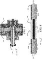
wire coating 112 or similar wire coatings may be specifically arranged to convey information regarding the contents of theouter core 102 orinner core 104, as detailed below with respect toFIG. 4. FIG. 3 illustrates anapparatus 300, for forming thermal sensor wires, such as a thethermal sensor wire 110. Theapparatus 300 may represent an extrusion apparatus, having acentral orifice 302, where theinner core 104 is drawn or extruded through, asecond orifice 304 for feeding theouter core 102 to form around theinner core 104, and athird orifice 306 for feeding thewire coating 112 around theouter core 102. -
FIG. 1C shows athermal sensor wire 120, where the cross-section is rectangular, rather than round or circular. As such, aninner core 126 may be rectangular shaped, while theouter core 124 has a rectangular cylindrical shape, and is surrounded by awire coating 122. Depending upon the application, the use of the rectangular, flat, or elongated cross-section of thethermal sensor wire 120 may be more appropriate than a circular-cross-section wire. -
FIG. 1D illustrates athermal sensor wire 130, having a round cross-section or circular cross-section, and anouter wire coating 131, disposed around acarrier portion 132. Here a plurality of inner wires are disposed within thecarrier portion 132. These wires are shown as firstinner wire 134, secondinner wire 136, and thirdinner wire 138. These inner wires may differ from one another in thermal properties. For example, the firstinner wire 134 may be formed using a firstthermal sensing material 142 characterized by a first transition temperature, the secondinner wire 136 may be formed using a secondthermal sensing material 146 characterized by a second transition temperature, while the thirdinner wire 138 may be formed using a thirdthermal sensing material 150 characterized by a third transition temperature. All these transition temperatures may differ from one another. As such, thethermal sensor wire 130 may be suitable for use where sensing of temperature is useful at multiple different temperatures for a device to be protected. For example, the first transition temperature may be 60 C, the second transition temperature may be 70 C, while the third transition temperature may be 80 °C. Each of the inner wires may be separately coupled to circuitry or devices to indicate when a given temperature has been reached. In the case of protecting a battery, when 60 °C is exceeded at a given location on a battery, the firstinner wire 134, undergoing a sharp change in resistance, may trigger a first warning signal to be sent. When 70 °C is exceeded, the secondinner wire 136 may trigger a second signal, such as a higher level alarm, while when 80 °C is exceeded, the thirdinner wire 138 may trigger a procedure, such as a shutdown of power. - While
FIG. 1D illustrates three inner wires, fewer or more inner wires may be used to form a multi-temperature sensor wire. Notably, for ease of assembly and wiring, theinner coating 140,inner coating 144, andinner coating 148, of the respective inner wires, may differ from one another, such as in color. -
FIG. 1E illustrates athermal sensor wire 160, having a flat, elongated or rectangular cross-section, and anouter wire coating 162, disposed around acarrier portion 161. LikeFIG. 1D , a plurality of inner wires are disposed within thecarrier portion 161. These wires are shown as firstinner wire 164, secondinner wire 166, and thirdinner wire 168. These inner wires may differ from one another in thermal properties. For example, the firstinner wire 164 may be formed using a first thermal sensing material 172 (surrounded by inner coating 170) characterized by a first transition temperature, the secondinner wire 166 may be formed using a second thermal sensing material 176 (surrounded by inner coating 174) characterized by a second transition temperature, while the thirdinner wire 168 may be formed using a third thermal sensing material 180 (surrounded by coating 170) characterized by a third transition temperature. All these transition temperatures may differ from one another. As such, thethermal sensor wire 160 may be suitable for use where sensing of temperature is useful at multiple different temperatures for a device to be protected, as in the case of thethermal sensor wire 130, discussed above. -
FIG. 4 depicts athermal sensor wire 400, according to the disclosure. Thethermal sensor wire 400 includes aninner core 402, anouter core 404, disposed around theinner core 402, and awire coating 406, disposed around theouter core 404. Theinner core 402 may be segmented as shown, in that theinner core 402 comprises afirst core segment 402A and asecond core segment 402B, disposed longitudinally with respect to one another along the wire axis (z-axis), wherein thefirst core segment 402A comprises thermal sensing material that has a transition temperature where electrical conductivity changes by at least one order of magnitude within a targeted temperature range. As such, thefirst core segment 402A may include a PPTC material or an NTC material, for example. In contrast, thesecond core segment 402B does not exhibit a transition temperature within the targeted temperature range. For example, thethermal sensor wire 400 may be designed to detect temperature excursions above approximately 80C, so the material of thefirst core segment 402A may be designed to have a transition temperature in the range somewhere between 70 °C to 80 °C or so. - The
inner core 402 may be generally electrically conductive, including thesecond core segment 402B, so when a transition takes place at 80 °C in thefirst core segment 402A, the overall resistance and resistance change of theinner core 402 may be readily measurable. Thefirst core segment 402A may be repeated multiple times along theinner core 402 as shown inFIG. 4 . For example, thethermal sensor wire 400 may be applied to a battery pack where a plurality offirst core segments 402A are applied to the surface of battery regions to monitor temperature. Moreover, thesecond core segment 402B may include a simple conductor, such as carbon black, that does not exhibit a transition temperature where electrical conductivity changes by an order of magnitude or more within several degrees (at least not within the targeted temperature range to be monitored). Thus, thesecond core segment 402B may be arranged next to regions where temperature is not to be monitored, such as gaps between batteries, edges, and so forth. In this manner, PPTC material or NTC material need not be supplied throughout the entirety of theinner core 402, but just in select segments that can be selectively arranged adjacent to device regions to be monitored. - As further shown in
FIG. 4 , thewire coating 406 comprises afirst coating segment 406A, disposed around thefirst core segment 402A, and asecond coating segment 406B, disposed around thesecond core segment 402B, wherein thefirst coating segment 406A has a first color, and thesecond core segment 406B has a second color, different from the first color. In this manner, thethermal sensor wire 400 provides an indication of the location of thermal sensing portions (first core segments 402A) along the length, facilitating appropriate application of the thermal sensing portions of thethermal sensor wire 400 to the portions of the device to be monitored or protected. - Thermal sensor wires may be formed by any suitable technique, including extrusion of a PTC material as a single wire, where the cross-section is controlled by various dies from round to rectangular; coextrusion of multiple layers to form a multilayer wire configuration with different functional properties where some layers are conductive an others are not conductive; extruded with a variable cross-section along the length of a wire; laminated/calendered segments from multiple "wires" with periodically different length segments along the length performed into roll to roll or a batch process; hot melt pressed or printed and relaminated. An inner core portion that forms a thermal sensing portion of a thermal sensor wire may be extruded at a constant diameter. The inner core portion may be extruded to generate a variable diameter in the inner core portion. For example, the overall resistance of the wire may be maintained at an acceptable level by having a first diameter of the inner core portion over certain lengths of the wire, while the diameter may be changed at certain points to a second diameter that is less. For example, the diameter of the (conductive) inner core portion may be established at a first value along segments of the wire where no thermal sensing is to take place, and may be a second value along segments where thermal sensing is to be performed.
- Turning now to
FIG. 5 there is shown anexemplary process flow 500. Atblock 502, a carrier portion of a thermal sensor wire is formed. The carrier portion may extend along a long axis of the thermal sensor wire. - At
block 504, a thermal sensing material is formed into a thermal sensing portion of the thermal sensor wire, where the thermal sensing portion is elongated along the length of the thermal sensor wire, and adjacent to the carrier portion. The thermal sensing portion may be formed as a core portion, disposed within the carrier portion. Alternatively the carrier portion may be formed as the core portion, within a thermal sensing portion. - The thermal sensing material may include a polymer positive temperature coefficient (PPTC) material or a negative temperature coefficient (NTC) material. The thermal sensing material may be characterized by a thermal transition within a targeted temperature range. For example, a thermal transition may involve an increase or decrease in resistance by one order of magnitude, two orders or magnitude, four orders of magnitude, and so forth, within a narrow temperature range, such as within several degrees C. The targeted range for the thermal transition may be arranged according to application, but may generally lie within a range of - 50 °C to 200 °C. Contrariwise, the carrier portion may be formed of a carrier material, not having a thermal transition within the targeted temperature range, meaning the resistance does not change abruptly, such as by a factor of 10 (one order of magnitude) or more over a narrow temperature range, such as several degrees C, within the targeted temperature range. Thus, the thermal sensor wire may exhibit a sharp resistance change due just to a thermal transition experienced by the thermal sensing material within a targeted temperature range.
- The thermal sensing portion may be formed into a plurality of different inner wires, where each inner wire includes a thermal sensing material having a given transition temperature. For example, three different inner wires may be formed using three different thermal sensing materials, having three different transition temperatures. The three different inner wires may be coated with different respective coatings for the purpose of identification, and may be disposed in a common carrier portion of a thermal sensing wire that includes a general coating, disposed around the carrier portion.
- At
block 506, a coating is formed around the thermal sensing portion and the carrier portion. The coating may be an electrical insulator as in known wire coatings. - The thermal sensing portion may be formed into a plurality of different inner wires, where each inner wire includes a thermal sensing material having a given transition temperature. For example, three different inner wires may be formed using three different thermal sensing materials, having three different transition temperatures. The three different inner wires may be coated with different respective coatings for the purpose of identification, and may be disposed in a common carrier portion of a thermal sensing wire that includes a general coating, disposed around the carrier portion.
- In summary, the disclosure may be used for over-current and/or over-temperature protection similar to standard PPTC devices. A thermal sensor wire may be arranged as a sensing element as a continuous PPTC structure; or in multiple temperature sensing areas in series and/or parallel electrical configurations. Digital elements may be placed in series where resistance/impedance is low during normal operation, and is high when an anomalous condition allows for use of a simple digital signal that can be detected by a microprocessor or used to drive a electrical switch such as a relay or a field effect transistor.
Claims (15)
- A thermal sensor wire, comprising:a thermal sensing portion extending along a wire axis of the thermal sensor wire; anda carrier portion, the carrier portion extending along the wire axis, adjacent to the thermal sensing portion, the thermal sensing portion comprising a polymer positive temperature coefficient (PPTC) material or a negative temperature coefficient (NTC) material.
- The thermal sensor wire of claim 1, further comprising a round cross-section or a rectangular cross-section.
- The thermal sensor wire of claim 1 or 2, further comprising a plurality of layers having different functional properties, wherein the thermal sensing portion comprises a first layer that is electrically conductive, and wherein a second layer is electrically insulating.
- The thermal sensor wire of any of the preceding claims, the thermal sensing portion further comprising a variable cross-section along a length of the thermal sensor wire.
- The thermal sensor wire of any of the preceding claims, the thermal sensing portion comprising an inner core, the carrier portion disposed circumferentially around the inner core, further comprising: a wire coating, disposed around the carrier portion, preferably
wherein the inner core comprises a first core segment and a second core segment, disposed longitudinally with respect to one another along the wire axis, wherein the first core segment comprises a transition temperature where electrical conductivity changes by at least one order of magnitude within a targeted temperature range, wherein the second core segment does not exhibit a transition temperature within the targeted temperature range, more preferably
wherein the wire coating comprises a first coating segment, disposed around the first core segment, and a second coating segment, disposed around the second core segment, wherein the first coating segment has a first color, and the second core segment has a second color, different from the first color. - The thermal sensor wire of any of the preceding claims, further comprising:an outer wire coating, disposed around the carrier portion; anda plurality of inner wires, disposed within the carrier portion,wherein the thermal sensing portion is disposed in a first inner wire of the plurality of inner wires, and comprises a first thermal sensing material, having a first transition temperature,wherein the plurality of inner wires comprises at least one additional wire, comprising a second thermal sensing material, having a second transition temperature, different from the first transition temperature.
- The thermal sensor wire of any of the preceding claims, comprising a plurality of laminated/calendered segments, formed from multiple wires having periodically different length segments along a length of the thermal sensor wire.
- A method of forming a thermal sensor wire, comprising:forming a carrier portion of the thermal sensor wire, elongated along a length of the thermal sensor wire; andforming a thermal sensing material into a thermal sensing portion of the thermal sensor wire, elongated along the length of the thermals sensor wire, and adjacent to the carrier portion,wherein the thermal sensing material comprises a polymer positive temperature coefficient (PPTC) material or a negative temperature coefficient (NTC) material, characterized by a thermal transition within a targeted temperature range, wherein the carrier portion comprises a carrier material, not having a thermal transition within the targeted temperature range.
- The method of claim 8, further comprising:
forming the thermal sensing material as an inner core portion of the thermal sensor wire; and forming the carrier portion around the inner core portion. - The method of claim 8 or 9, further comprising extruding the inner core portion at a constant diameter, or comprising extruding the inner core portion to generate a variable diameter in the core portion.
- The method of any of the claims 8 to 10, comprising forming the thermal sensing material and the carrier portion as a series of layers in a multilayer wire configuration.
- The method of any of the claims 8-11, the forming the thermal sensing material as a core portion further comprising:extruding the thermal sensing material to form a first core segment of the core portion; andextruding a second material to form a second core segment of the core portion, after the extruding the thermal sensing material, wherein the first core segment comprises a transition temperature where electrical conductivity changes by at least one order of magnitude within a targeted temperature range, wherein the core segment does not exhibit a transition temperature within the targeted temperature range.
- The method of claim 12 , further comprising:
forming a coating around the carrier portion, wherein the forming the coating further comprises:forming a first coating segment, around the first core segment, andforming a second coating segment, around the second core segment, wherein the first coating segment has a first color, and the second core segment has a second color, different from the first color. - The method of any of the claims 8-13, wherein the thermal sensing material comprises a first thermal sensing material and a second thermal sensing material, wherein the first thermal sensing material and the second thermal sensing material are extruded as a first wire and a second wire, disposed within the carrier material, wherein the first thermal sensing material comprises a first transition temperature and the second thermal sensing material comprises a second transition temperature, different from the first transition temperature.
- A device, comprising:a battery portion; anda thermal sensor wire, disposed in contact with the battery portion, wherein the thermal sensor wire comprises:a thermal sensing portion extending along a wire axis of the thermal sensor wire; anda carrier portion, the carrier portion extending along the wire axis, adjacent to the thermal sensing portion, the thermal sensing portion comprising a polymer positive temperature coefficient (PPTC) material or a negative temperature coefficient (NTC) material, preferably wherein the thermal sensing portion comprises an inner core, the carrier portion disposed circumferentially around the inner core, further comprising: a wire coating, disposed around the carrier portion.
Applications Claiming Priority (1)
| Application Number | Priority Date | Filing Date | Title |
|---|---|---|---|
| US16/686,182 US11614369B2 (en) | 2019-11-17 | 2019-11-17 | Thermal sensing wire and techniques for thermal sensing |
Publications (1)
| Publication Number | Publication Date |
|---|---|
| EP3822599A1 true EP3822599A1 (en) | 2021-05-19 |
Family
ID=73059462
Family Applications (1)
| Application Number | Title | Priority Date | Filing Date |
|---|---|---|---|
| EP20205285.8A Pending EP3822599A1 (en) | 2019-11-17 | 2020-11-02 | Thermal sensing wire and techniques for thermal sensing |
Country Status (6)
| Country | Link |
|---|---|
| US (1) | US11614369B2 (en) |
| EP (1) | EP3822599A1 (en) |
| JP (1) | JP7563738B2 (en) |
| KR (1) | KR20210060309A (en) |
| CN (1) | CN112816089B (en) |
| TW (1) | TWI870502B (en) |
Cited By (1)
| Publication number | Priority date | Publication date | Assignee | Title |
|---|---|---|---|---|
| EP4517984A1 (en) * | 2023-08-31 | 2025-03-05 | Abb Schweiz Ag | Battery arrangement |
Families Citing this family (4)
| Publication number | Priority date | Publication date | Assignee | Title |
|---|---|---|---|---|
| US20240154402A1 (en) * | 2022-11-09 | 2024-05-09 | Littelfuse, Inc. | Temperature sensing tape having a temperature sensor element with multiple crystallization points |
| CN115816798B (en) * | 2022-11-17 | 2025-11-04 | 南京贝迪新材料科技股份有限公司 | An extrusion preparation method and system for LCP membrane production |
| CN118299503B (en) * | 2023-01-04 | 2026-03-03 | 宁德时代新能源科技股份有限公司 | Electrode plate, preparation method thereof, secondary battery comprising electrode plate and electricity utilization device |
| CN120740782B (en) * | 2025-08-21 | 2025-12-30 | 成都凯天电子股份有限公司 | Temperature sensor for controlling opening degree of valve of air-inducing temperature-controlling system |
Citations (5)
| Publication number | Priority date | Publication date | Assignee | Title |
|---|---|---|---|---|
| US3435401A (en) * | 1966-10-05 | 1969-03-25 | Texas Instruments Inc | Insulated electrical conductors |
| US5185594A (en) * | 1991-05-20 | 1993-02-09 | Furon Company | Temperature sensing cable device and method of making same |
| US20120106593A1 (en) * | 2010-11-02 | 2012-05-03 | Sinoelectric Powertrain Corporation | Thermal interlock for battery pack, device, system and method |
| DE102014017115A1 (en) * | 2014-11-19 | 2015-06-11 | Daimler Ag | Battery device with temperature monitoring |
| WO2020016853A1 (en) * | 2018-07-20 | 2020-01-23 | LMS Consulting Group | Thermal substrate with high-resistance magnification and positive temperature coefficient |
Family Cites Families (7)
| Publication number | Priority date | Publication date | Assignee | Title |
|---|---|---|---|---|
| JP2004185947A (en) | 2002-12-03 | 2004-07-02 | Totoku Electric Co Ltd | Thermal heating wire |
| TW201249244A (en) * | 2011-05-23 | 2012-12-01 | Ching-Chuan Wang | Safety control structure for heater wire |
| CN204946592U (en) * | 2015-09-15 | 2016-01-06 | 谢斌鑫 | A kind of temperature sensing cable and heat detector |
| CN105390219A (en) * | 2015-12-14 | 2016-03-09 | 天津凯华绝缘材料股份有限公司 | Component with over-voltage over-current protective effect and manufacturing process of the same |
| CN105809876B (en) * | 2016-05-06 | 2018-11-02 | 曾以若 | A kind of line type temperature-sensitive detection cable |
| CN109425440A (en) * | 2017-09-05 | 2019-03-05 | 力特有限公司 | Temperature sensing band |
| US11525739B2 (en) * | 2018-05-08 | 2022-12-13 | Texas Instruments Incorporated | Thermistor die-based thermal probe |
-
2019
- 2019-11-17 US US16/686,182 patent/US11614369B2/en active Active
-
2020
- 2020-10-19 KR KR1020200135084A patent/KR20210060309A/en active Pending
- 2020-10-26 JP JP2020179259A patent/JP7563738B2/en active Active
- 2020-11-02 EP EP20205285.8A patent/EP3822599A1/en active Pending
- 2020-11-04 CN CN202011216504.9A patent/CN112816089B/en active Active
- 2020-11-10 TW TW109139088A patent/TWI870502B/en active
Patent Citations (5)
| Publication number | Priority date | Publication date | Assignee | Title |
|---|---|---|---|---|
| US3435401A (en) * | 1966-10-05 | 1969-03-25 | Texas Instruments Inc | Insulated electrical conductors |
| US5185594A (en) * | 1991-05-20 | 1993-02-09 | Furon Company | Temperature sensing cable device and method of making same |
| US20120106593A1 (en) * | 2010-11-02 | 2012-05-03 | Sinoelectric Powertrain Corporation | Thermal interlock for battery pack, device, system and method |
| DE102014017115A1 (en) * | 2014-11-19 | 2015-06-11 | Daimler Ag | Battery device with temperature monitoring |
| WO2020016853A1 (en) * | 2018-07-20 | 2020-01-23 | LMS Consulting Group | Thermal substrate with high-resistance magnification and positive temperature coefficient |
Cited By (1)
| Publication number | Priority date | Publication date | Assignee | Title |
|---|---|---|---|---|
| EP4517984A1 (en) * | 2023-08-31 | 2025-03-05 | Abb Schweiz Ag | Battery arrangement |
Also Published As
| Publication number | Publication date |
|---|---|
| US11614369B2 (en) | 2023-03-28 |
| US20210148767A1 (en) | 2021-05-20 |
| JP7563738B2 (en) | 2024-10-08 |
| TW202121449A (en) | 2021-06-01 |
| CN112816089A (en) | 2021-05-18 |
| TWI870502B (en) | 2025-01-21 |
| KR20210060309A (en) | 2021-05-26 |
| CN112816089B (en) | 2025-09-16 |
| JP2021082813A (en) | 2021-05-27 |
Similar Documents
| Publication | Publication Date | Title |
|---|---|---|
| EP3822599A1 (en) | Thermal sensing wire and techniques for thermal sensing | |
| US10458860B2 (en) | Capacitive temperature sensing for electrical conductor | |
| US6958463B1 (en) | Heater with simultaneous hot spot and mechanical intrusion protection | |
| US4361799A (en) | Over-temperature sense and locate device | |
| US5313185A (en) | Temperature sensing cable device and method of making same | |
| WO2008104105A1 (en) | A multifunctional linear cable temperature-sensing fire detector | |
| EP1273206A1 (en) | Electric cable having braidless polymeric ground plane providing fault detection | |
| JP5562678B2 (en) | Heat sensitive wire and method for producing the same | |
| JP2023109880A (en) | temperature sensing tape | |
| CN100495455C (en) | A Restorable Cable Type Differential Temperature Sensing Detector | |
| EP1645167B2 (en) | Heating blanket | |
| US4891500A (en) | Self-healing parallel heating tape | |
| JPS62271304A (en) | Excessive temperature sensor for power source cable | |
| CN103096537A (en) | Linear heating wire device | |
| CN210777039U (en) | Cable type linear temperature-sensing fire detector capable of alarming fire in short circuit | |
| US20100142584A1 (en) | Digital linear heat detector with thermal activation confirmation | |
| JP5562677B2 (en) | Cord heater and surface heater with temperature detection function | |
| KR102502765B1 (en) | Heating apparatus for electric blanket and manufacturing method thereof | |
| CN212113307U (en) | Temperature sensing power cable | |
| JP5297686B2 (en) | Manufacturing method of temperature detector | |
| JPH0465509B2 (en) | ||
| CN200983191Y (en) | A linear temperature sensing part with window at insulation layer | |
| CN101183481B (en) | Thermal partial discharge breakthrough type cable linear temperature-sensitive detector and alarm method thereof | |
| JPH0547459A (en) | Heat sensitive heater wire | |
| CN206301624U (en) | A kind of cable with cable core overheating prompt function |
Legal Events
| Date | Code | Title | Description |
|---|---|---|---|
| PUAI | Public reference made under article 153(3) epc to a published international application that has entered the european phase |
Free format text: ORIGINAL CODE: 0009012 |
|
| STAA | Information on the status of an ep patent application or granted ep patent |
Free format text: STATUS: THE APPLICATION HAS BEEN PUBLISHED |
|
| AK | Designated contracting states |
Kind code of ref document: A1 Designated state(s): AL AT BE BG CH CY CZ DE DK EE ES FI FR GB GR HR HU IE IS IT LI LT LU LV MC MK MT NL NO PL PT RO RS SE SI SK SM TR |
|
| STAA | Information on the status of an ep patent application or granted ep patent |
Free format text: STATUS: REQUEST FOR EXAMINATION WAS MADE |
|
| 17P | Request for examination filed |
Effective date: 20211115 |
|
| RBV | Designated contracting states (corrected) |
Designated state(s): AL AT BE BG CH CY CZ DE DK EE ES FI FR GB GR HR HU IE IS IT LI LT LU LV MC MK MT NL NO PL PT RO RS SE SI SK SM TR |
|
| REG | Reference to a national code |
Ref country code: DE Ref legal event code: R079 Free format text: PREVIOUS MAIN CLASS: G01K0007220000 Ipc: H01B0005020000 |
|
| GRAP | Despatch of communication of intention to grant a patent |
Free format text: ORIGINAL CODE: EPIDOSNIGR1 |
|
| STAA | Information on the status of an ep patent application or granted ep patent |
Free format text: STATUS: GRANT OF PATENT IS INTENDED |