EP3822571A1 - Aircraft heat exchanger assembly - Google Patents
Aircraft heat exchanger assembly Download PDFInfo
- Publication number
- EP3822571A1 EP3822571A1 EP20207313.6A EP20207313A EP3822571A1 EP 3822571 A1 EP3822571 A1 EP 3822571A1 EP 20207313 A EP20207313 A EP 20207313A EP 3822571 A1 EP3822571 A1 EP 3822571A1
- Authority
- EP
- European Patent Office
- Prior art keywords
- heat exchanger
- flowpath
- plate
- face
- flow
- Prior art date
- Legal status (The legal status is an assumption and is not a legal conclusion. Google has not performed a legal analysis and makes no representation as to the accuracy of the status listed.)
- Withdrawn
Links
- 238000005266 casting Methods 0.000 claims description 17
- PXHVJJICTQNCMI-UHFFFAOYSA-N Nickel Chemical compound [Ni] PXHVJJICTQNCMI-UHFFFAOYSA-N 0.000 claims description 13
- 238000000034 method Methods 0.000 claims description 10
- 238000004519 manufacturing process Methods 0.000 claims description 6
- 229910052759 nickel Inorganic materials 0.000 claims description 6
- 229910045601 alloy Inorganic materials 0.000 claims description 4
- 239000000956 alloy Substances 0.000 claims description 4
- 230000008878 coupling Effects 0.000 claims description 4
- 238000010168 coupling process Methods 0.000 claims description 4
- 238000005859 coupling reaction Methods 0.000 claims description 4
- 238000005219 brazing Methods 0.000 claims description 3
- 230000007613 environmental effect Effects 0.000 claims description 3
- 238000011144 upstream manufacturing Methods 0.000 description 7
- 238000001816 cooling Methods 0.000 description 5
- 230000013011 mating Effects 0.000 description 4
- 238000009792 diffusion process Methods 0.000 description 3
- 229910000601 superalloy Inorganic materials 0.000 description 3
- 230000000295 complement effect Effects 0.000 description 2
- 238000003754 machining Methods 0.000 description 2
- 239000000654 additive Substances 0.000 description 1
- 230000000996 additive effect Effects 0.000 description 1
- 238000000149 argon plasma sintering Methods 0.000 description 1
- 230000006835 compression Effects 0.000 description 1
- 238000007906 compression Methods 0.000 description 1
- 230000004069 differentiation Effects 0.000 description 1
- 238000000605 extraction Methods 0.000 description 1
- 238000000227 grinding Methods 0.000 description 1
- 229910052735 hafnium Inorganic materials 0.000 description 1
- 239000012535 impurity Substances 0.000 description 1
- 230000010354 integration Effects 0.000 description 1
- 238000005304 joining Methods 0.000 description 1
- 239000000463 material Substances 0.000 description 1
- 239000002184 metal Substances 0.000 description 1
- 229910052751 metal Inorganic materials 0.000 description 1
- 238000003801 milling Methods 0.000 description 1
- 239000000203 mixture Substances 0.000 description 1
- 238000012986 modification Methods 0.000 description 1
- 230000004048 modification Effects 0.000 description 1
- 230000009467 reduction Effects 0.000 description 1
- 238000000110 selective laser sintering Methods 0.000 description 1
- 230000002123 temporal effect Effects 0.000 description 1
Images




Classifications
-
- F—MECHANICAL ENGINEERING; LIGHTING; HEATING; WEAPONS; BLASTING
- F28—HEAT EXCHANGE IN GENERAL
- F28D—HEAT-EXCHANGE APPARATUS, NOT PROVIDED FOR IN ANOTHER SUBCLASS, IN WHICH THE HEAT-EXCHANGE MEDIA DO NOT COME INTO DIRECT CONTACT
- F28D1/00—Heat-exchange apparatus having stationary conduit assemblies for one heat-exchange medium only, the media being in contact with different sides of the conduit wall, in which the other heat-exchange medium is a large body of fluid, e.g. domestic or motor car radiators
- F28D1/02—Heat-exchange apparatus having stationary conduit assemblies for one heat-exchange medium only, the media being in contact with different sides of the conduit wall, in which the other heat-exchange medium is a large body of fluid, e.g. domestic or motor car radiators with heat-exchange conduits immersed in the body of fluid
- F28D1/03—Heat-exchange apparatus having stationary conduit assemblies for one heat-exchange medium only, the media being in contact with different sides of the conduit wall, in which the other heat-exchange medium is a large body of fluid, e.g. domestic or motor car radiators with heat-exchange conduits immersed in the body of fluid with plate-like or laminated conduits
-
- F—MECHANICAL ENGINEERING; LIGHTING; HEATING; WEAPONS; BLASTING
- F02—COMBUSTION ENGINES; HOT-GAS OR COMBUSTION-PRODUCT ENGINE PLANTS
- F02C—GAS-TURBINE PLANTS; AIR INTAKES FOR JET-PROPULSION PLANTS; CONTROLLING FUEL SUPPLY IN AIR-BREATHING JET-PROPULSION PLANTS
- F02C6/00—Plural gas-turbine plants; Combinations of gas-turbine plants with other apparatus; Adaptations of gas-turbine plants for special use
- F02C6/04—Gas-turbine plants providing heated or pressurised working fluid for other apparatus, e.g. without mechanical power output
- F02C6/06—Gas-turbine plants providing heated or pressurised working fluid for other apparatus, e.g. without mechanical power output providing compressed gas
- F02C6/08—Gas-turbine plants providing heated or pressurised working fluid for other apparatus, e.g. without mechanical power output providing compressed gas the gas being bled from the gas-turbine compressor
-
- F—MECHANICAL ENGINEERING; LIGHTING; HEATING; WEAPONS; BLASTING
- F02—COMBUSTION ENGINES; HOT-GAS OR COMBUSTION-PRODUCT ENGINE PLANTS
- F02C—GAS-TURBINE PLANTS; AIR INTAKES FOR JET-PROPULSION PLANTS; CONTROLLING FUEL SUPPLY IN AIR-BREATHING JET-PROPULSION PLANTS
- F02C7/00—Features, components parts, details or accessories, not provided for in, or of interest apart form groups F02C1/00 - F02C6/00; Air intakes for jet-propulsion plants
- F02C7/12—Cooling of plants
- F02C7/14—Cooling of plants of fluids in the plant, e.g. lubricant or fuel
-
- F—MECHANICAL ENGINEERING; LIGHTING; HEATING; WEAPONS; BLASTING
- F02—COMBUSTION ENGINES; HOT-GAS OR COMBUSTION-PRODUCT ENGINE PLANTS
- F02C—GAS-TURBINE PLANTS; AIR INTAKES FOR JET-PROPULSION PLANTS; CONTROLLING FUEL SUPPLY IN AIR-BREATHING JET-PROPULSION PLANTS
- F02C7/00—Features, components parts, details or accessories, not provided for in, or of interest apart form groups F02C1/00 - F02C6/00; Air intakes for jet-propulsion plants
- F02C7/12—Cooling of plants
- F02C7/14—Cooling of plants of fluids in the plant, e.g. lubricant or fuel
- F02C7/141—Cooling of plants of fluids in the plant, e.g. lubricant or fuel of working fluid
-
- F—MECHANICAL ENGINEERING; LIGHTING; HEATING; WEAPONS; BLASTING
- F28—HEAT EXCHANGE IN GENERAL
- F28D—HEAT-EXCHANGE APPARATUS, NOT PROVIDED FOR IN ANOTHER SUBCLASS, IN WHICH THE HEAT-EXCHANGE MEDIA DO NOT COME INTO DIRECT CONTACT
- F28D1/00—Heat-exchange apparatus having stationary conduit assemblies for one heat-exchange medium only, the media being in contact with different sides of the conduit wall, in which the other heat-exchange medium is a large body of fluid, e.g. domestic or motor car radiators
- F28D1/02—Heat-exchange apparatus having stationary conduit assemblies for one heat-exchange medium only, the media being in contact with different sides of the conduit wall, in which the other heat-exchange medium is a large body of fluid, e.g. domestic or motor car radiators with heat-exchange conduits immersed in the body of fluid
- F28D1/04—Heat-exchange apparatus having stationary conduit assemblies for one heat-exchange medium only, the media being in contact with different sides of the conduit wall, in which the other heat-exchange medium is a large body of fluid, e.g. domestic or motor car radiators with heat-exchange conduits immersed in the body of fluid with tubular conduits
- F28D1/053—Heat-exchange apparatus having stationary conduit assemblies for one heat-exchange medium only, the media being in contact with different sides of the conduit wall, in which the other heat-exchange medium is a large body of fluid, e.g. domestic or motor car radiators with heat-exchange conduits immersed in the body of fluid with tubular conduits the conduits being straight
- F28D1/0535—Heat-exchange apparatus having stationary conduit assemblies for one heat-exchange medium only, the media being in contact with different sides of the conduit wall, in which the other heat-exchange medium is a large body of fluid, e.g. domestic or motor car radiators with heat-exchange conduits immersed in the body of fluid with tubular conduits the conduits being straight the conduits having a non-circular cross-section
- F28D1/05366—Assemblies of conduits connected to common headers, e.g. core type radiators
-
- F—MECHANICAL ENGINEERING; LIGHTING; HEATING; WEAPONS; BLASTING
- F28—HEAT EXCHANGE IN GENERAL
- F28D—HEAT-EXCHANGE APPARATUS, NOT PROVIDED FOR IN ANOTHER SUBCLASS, IN WHICH THE HEAT-EXCHANGE MEDIA DO NOT COME INTO DIRECT CONTACT
- F28D7/00—Heat-exchange apparatus having stationary tubular conduit assemblies for both heat-exchange media, the media being in contact with different sides of a conduit wall
- F28D7/16—Heat-exchange apparatus having stationary tubular conduit assemblies for both heat-exchange media, the media being in contact with different sides of a conduit wall the conduits being arranged in parallel spaced relation
- F28D7/1684—Heat-exchange apparatus having stationary tubular conduit assemblies for both heat-exchange media, the media being in contact with different sides of a conduit wall the conduits being arranged in parallel spaced relation the conduits having a non-circular cross-section
-
- F—MECHANICAL ENGINEERING; LIGHTING; HEATING; WEAPONS; BLASTING
- F28—HEAT EXCHANGE IN GENERAL
- F28D—HEAT-EXCHANGE APPARATUS, NOT PROVIDED FOR IN ANOTHER SUBCLASS, IN WHICH THE HEAT-EXCHANGE MEDIA DO NOT COME INTO DIRECT CONTACT
- F28D9/00—Heat-exchange apparatus having stationary plate-like or laminated conduit assemblies for both heat-exchange media, the media being in contact with different sides of a conduit wall
- F28D9/0081—Heat-exchange apparatus having stationary plate-like or laminated conduit assemblies for both heat-exchange media, the media being in contact with different sides of a conduit wall the conduits for one heat-exchange medium being formed by a single plate-like element ; the conduits for one heat-exchange medium being integrated in one single plate-like element
-
- F—MECHANICAL ENGINEERING; LIGHTING; HEATING; WEAPONS; BLASTING
- F28—HEAT EXCHANGE IN GENERAL
- F28F—DETAILS OF HEAT-EXCHANGE AND HEAT-TRANSFER APPARATUS, OF GENERAL APPLICATION
- F28F1/00—Tubular elements; Assemblies of tubular elements
- F28F1/02—Tubular elements of cross-section which is non-circular
- F28F1/025—Tubular elements of cross-section which is non-circular with variable shape, e.g. with modified tube ends, with different geometrical features
-
- F—MECHANICAL ENGINEERING; LIGHTING; HEATING; WEAPONS; BLASTING
- F28—HEAT EXCHANGE IN GENERAL
- F28F—DETAILS OF HEAT-EXCHANGE AND HEAT-TRANSFER APPARATUS, OF GENERAL APPLICATION
- F28F1/00—Tubular elements; Assemblies of tubular elements
- F28F1/10—Tubular elements and assemblies thereof with means for increasing heat-transfer area, e.g. with fins, with projections, with recesses
- F28F1/12—Tubular elements and assemblies thereof with means for increasing heat-transfer area, e.g. with fins, with projections, with recesses the means being only outside the tubular element
- F28F1/24—Tubular elements and assemblies thereof with means for increasing heat-transfer area, e.g. with fins, with projections, with recesses the means being only outside the tubular element and extending transversely
- F28F1/26—Tubular elements and assemblies thereof with means for increasing heat-transfer area, e.g. with fins, with projections, with recesses the means being only outside the tubular element and extending transversely the means being integral with the element
-
- F—MECHANICAL ENGINEERING; LIGHTING; HEATING; WEAPONS; BLASTING
- F28—HEAT EXCHANGE IN GENERAL
- F28F—DETAILS OF HEAT-EXCHANGE AND HEAT-TRANSFER APPARATUS, OF GENERAL APPLICATION
- F28F21/00—Constructions of heat-exchange apparatus characterised by the selection of particular materials
- F28F21/08—Constructions of heat-exchange apparatus characterised by the selection of particular materials of metal
- F28F21/081—Heat exchange elements made from metals or metal alloys
- F28F21/082—Heat exchange elements made from metals or metal alloys from steel or ferrous alloys
- F28F21/083—Heat exchange elements made from metals or metal alloys from steel or ferrous alloys from stainless steel
-
- F—MECHANICAL ENGINEERING; LIGHTING; HEATING; WEAPONS; BLASTING
- F28—HEAT EXCHANGE IN GENERAL
- F28F—DETAILS OF HEAT-EXCHANGE AND HEAT-TRANSFER APPARATUS, OF GENERAL APPLICATION
- F28F21/00—Constructions of heat-exchange apparatus characterised by the selection of particular materials
- F28F21/08—Constructions of heat-exchange apparatus characterised by the selection of particular materials of metal
- F28F21/081—Heat exchange elements made from metals or metal alloys
- F28F21/087—Heat exchange elements made from metals or metal alloys from nickel or nickel alloys
-
- F—MECHANICAL ENGINEERING; LIGHTING; HEATING; WEAPONS; BLASTING
- F28—HEAT EXCHANGE IN GENERAL
- F28F—DETAILS OF HEAT-EXCHANGE AND HEAT-TRANSFER APPARATUS, OF GENERAL APPLICATION
- F28F3/00—Plate-like or laminated elements; Assemblies of plate-like or laminated elements
- F28F3/02—Elements or assemblies thereof with means for increasing heat-transfer area, e.g. with fins, with recesses, with corrugations
- F28F3/04—Elements or assemblies thereof with means for increasing heat-transfer area, e.g. with fins, with recesses, with corrugations the means being integral with the element
- F28F3/048—Elements or assemblies thereof with means for increasing heat-transfer area, e.g. with fins, with recesses, with corrugations the means being integral with the element in the form of ribs integral with the element or local variations in thickness of the element, e.g. grooves, microchannels
-
- F—MECHANICAL ENGINEERING; LIGHTING; HEATING; WEAPONS; BLASTING
- F28—HEAT EXCHANGE IN GENERAL
- F28F—DETAILS OF HEAT-EXCHANGE AND HEAT-TRANSFER APPARATUS, OF GENERAL APPLICATION
- F28F3/00—Plate-like or laminated elements; Assemblies of plate-like or laminated elements
- F28F3/12—Elements constructed in the shape of a hollow panel, e.g. with channels
-
- F—MECHANICAL ENGINEERING; LIGHTING; HEATING; WEAPONS; BLASTING
- F28—HEAT EXCHANGE IN GENERAL
- F28F—DETAILS OF HEAT-EXCHANGE AND HEAT-TRANSFER APPARATUS, OF GENERAL APPLICATION
- F28F9/00—Casings; Header boxes; Auxiliary supports for elements; Auxiliary members within casings
- F28F9/007—Auxiliary supports for elements
- F28F9/013—Auxiliary supports for elements for tubes or tube-assemblies
-
- F—MECHANICAL ENGINEERING; LIGHTING; HEATING; WEAPONS; BLASTING
- F28—HEAT EXCHANGE IN GENERAL
- F28F—DETAILS OF HEAT-EXCHANGE AND HEAT-TRANSFER APPARATUS, OF GENERAL APPLICATION
- F28F9/00—Casings; Header boxes; Auxiliary supports for elements; Auxiliary members within casings
- F28F9/02—Header boxes; End plates
-
- F—MECHANICAL ENGINEERING; LIGHTING; HEATING; WEAPONS; BLASTING
- F28—HEAT EXCHANGE IN GENERAL
- F28F—DETAILS OF HEAT-EXCHANGE AND HEAT-TRANSFER APPARATUS, OF GENERAL APPLICATION
- F28F9/00—Casings; Header boxes; Auxiliary supports for elements; Auxiliary members within casings
- F28F9/02—Header boxes; End plates
- F28F9/0246—Arrangements for connecting header boxes with flow lines
-
- F—MECHANICAL ENGINEERING; LIGHTING; HEATING; WEAPONS; BLASTING
- F28—HEAT EXCHANGE IN GENERAL
- F28F—DETAILS OF HEAT-EXCHANGE AND HEAT-TRANSFER APPARATUS, OF GENERAL APPLICATION
- F28F9/00—Casings; Header boxes; Auxiliary supports for elements; Auxiliary members within casings
- F28F9/02—Header boxes; End plates
- F28F9/026—Header boxes; End plates with static flow control means, e.g. with means for uniformly distributing heat exchange media into conduits
- F28F9/0265—Header boxes; End plates with static flow control means, e.g. with means for uniformly distributing heat exchange media into conduits by using guiding means or impingement means inside the header box
- F28F9/0268—Header boxes; End plates with static flow control means, e.g. with means for uniformly distributing heat exchange media into conduits by using guiding means or impingement means inside the header box in the form of multiple deflectors for channeling the heat exchange medium
-
- F—MECHANICAL ENGINEERING; LIGHTING; HEATING; WEAPONS; BLASTING
- F28—HEAT EXCHANGE IN GENERAL
- F28F—DETAILS OF HEAT-EXCHANGE AND HEAT-TRANSFER APPARATUS, OF GENERAL APPLICATION
- F28F9/00—Casings; Header boxes; Auxiliary supports for elements; Auxiliary members within casings
- F28F9/02—Header boxes; End plates
- F28F9/04—Arrangements for sealing elements into header boxes or end plates
- F28F9/16—Arrangements for sealing elements into header boxes or end plates by permanent joints, e.g. by rolling
- F28F9/18—Arrangements for sealing elements into header boxes or end plates by permanent joints, e.g. by rolling by welding
- F28F9/182—Arrangements for sealing elements into header boxes or end plates by permanent joints, e.g. by rolling by welding the heat-exchange conduits having ends with a particular shape, e.g. deformed; the heat-exchange conduits or end plates having supplementary joining means, e.g. abutments
-
- F—MECHANICAL ENGINEERING; LIGHTING; HEATING; WEAPONS; BLASTING
- F28—HEAT EXCHANGE IN GENERAL
- F28F—DETAILS OF HEAT-EXCHANGE AND HEAT-TRANSFER APPARATUS, OF GENERAL APPLICATION
- F28F9/00—Casings; Header boxes; Auxiliary supports for elements; Auxiliary members within casings
- F28F9/26—Arrangements for connecting different sections of heat-exchange elements, e.g. of radiators
-
- F—MECHANICAL ENGINEERING; LIGHTING; HEATING; WEAPONS; BLASTING
- F28—HEAT EXCHANGE IN GENERAL
- F28F—DETAILS OF HEAT-EXCHANGE AND HEAT-TRANSFER APPARATUS, OF GENERAL APPLICATION
- F28F9/00—Casings; Header boxes; Auxiliary supports for elements; Auxiliary members within casings
- F28F9/26—Arrangements for connecting different sections of heat-exchange elements, e.g. of radiators
- F28F9/262—Arrangements for connecting different sections of heat-exchange elements, e.g. of radiators for radiators
-
- F—MECHANICAL ENGINEERING; LIGHTING; HEATING; WEAPONS; BLASTING
- F05—INDEXING SCHEMES RELATING TO ENGINES OR PUMPS IN VARIOUS SUBCLASSES OF CLASSES F01-F04
- F05D—INDEXING SCHEME FOR ASPECTS RELATING TO NON-POSITIVE-DISPLACEMENT MACHINES OR ENGINES, GAS-TURBINES OR JET-PROPULSION PLANTS
- F05D2260/00—Function
- F05D2260/20—Heat transfer, e.g. cooling
- F05D2260/213—Heat transfer, e.g. cooling by the provision of a heat exchanger within the cooling circuit
-
- F—MECHANICAL ENGINEERING; LIGHTING; HEATING; WEAPONS; BLASTING
- F28—HEAT EXCHANGE IN GENERAL
- F28D—HEAT-EXCHANGE APPARATUS, NOT PROVIDED FOR IN ANOTHER SUBCLASS, IN WHICH THE HEAT-EXCHANGE MEDIA DO NOT COME INTO DIRECT CONTACT
- F28D1/00—Heat-exchange apparatus having stationary conduit assemblies for one heat-exchange medium only, the media being in contact with different sides of the conduit wall, in which the other heat-exchange medium is a large body of fluid, e.g. domestic or motor car radiators
- F28D1/02—Heat-exchange apparatus having stationary conduit assemblies for one heat-exchange medium only, the media being in contact with different sides of the conduit wall, in which the other heat-exchange medium is a large body of fluid, e.g. domestic or motor car radiators with heat-exchange conduits immersed in the body of fluid
- F28D1/04—Heat-exchange apparatus having stationary conduit assemblies for one heat-exchange medium only, the media being in contact with different sides of the conduit wall, in which the other heat-exchange medium is a large body of fluid, e.g. domestic or motor car radiators with heat-exchange conduits immersed in the body of fluid with tubular conduits
- F28D1/0408—Multi-circuit heat exchangers, e.g. integrating different heat exchange sections in the same unit or heat exchangers for more than two fluids
-
- F—MECHANICAL ENGINEERING; LIGHTING; HEATING; WEAPONS; BLASTING
- F28—HEAT EXCHANGE IN GENERAL
- F28D—HEAT-EXCHANGE APPARATUS, NOT PROVIDED FOR IN ANOTHER SUBCLASS, IN WHICH THE HEAT-EXCHANGE MEDIA DO NOT COME INTO DIRECT CONTACT
- F28D1/00—Heat-exchange apparatus having stationary conduit assemblies for one heat-exchange medium only, the media being in contact with different sides of the conduit wall, in which the other heat-exchange medium is a large body of fluid, e.g. domestic or motor car radiators
- F28D1/02—Heat-exchange apparatus having stationary conduit assemblies for one heat-exchange medium only, the media being in contact with different sides of the conduit wall, in which the other heat-exchange medium is a large body of fluid, e.g. domestic or motor car radiators with heat-exchange conduits immersed in the body of fluid
- F28D2001/0253—Particular components
- F28D2001/026—Cores
-
- F—MECHANICAL ENGINEERING; LIGHTING; HEATING; WEAPONS; BLASTING
- F28—HEAT EXCHANGE IN GENERAL
- F28D—HEAT-EXCHANGE APPARATUS, NOT PROVIDED FOR IN ANOTHER SUBCLASS, IN WHICH THE HEAT-EXCHANGE MEDIA DO NOT COME INTO DIRECT CONTACT
- F28D21/00—Heat-exchange apparatus not covered by any of the groups F28D1/00 - F28D20/00
- F28D2021/0019—Other heat exchangers for particular applications; Heat exchange systems not otherwise provided for
- F28D2021/0021—Other heat exchangers for particular applications; Heat exchange systems not otherwise provided for for aircrafts or cosmonautics
-
- F—MECHANICAL ENGINEERING; LIGHTING; HEATING; WEAPONS; BLASTING
- F28—HEAT EXCHANGE IN GENERAL
- F28D—HEAT-EXCHANGE APPARATUS, NOT PROVIDED FOR IN ANOTHER SUBCLASS, IN WHICH THE HEAT-EXCHANGE MEDIA DO NOT COME INTO DIRECT CONTACT
- F28D21/00—Heat-exchange apparatus not covered by any of the groups F28D1/00 - F28D20/00
- F28D2021/0019—Other heat exchangers for particular applications; Heat exchange systems not otherwise provided for
- F28D2021/0026—Other heat exchangers for particular applications; Heat exchange systems not otherwise provided for for combustion engines, e.g. for gas turbines or for Stirling engines
-
- F—MECHANICAL ENGINEERING; LIGHTING; HEATING; WEAPONS; BLASTING
- F28—HEAT EXCHANGE IN GENERAL
- F28D—HEAT-EXCHANGE APPARATUS, NOT PROVIDED FOR IN ANOTHER SUBCLASS, IN WHICH THE HEAT-EXCHANGE MEDIA DO NOT COME INTO DIRECT CONTACT
- F28D7/00—Heat-exchange apparatus having stationary tubular conduit assemblies for both heat-exchange media, the media being in contact with different sides of a conduit wall
- F28D7/0066—Multi-circuit heat-exchangers, e.g. integrating different heat exchange sections in the same unit or heat-exchangers for more than two fluids
- F28D7/0083—Multi-circuit heat-exchangers, e.g. integrating different heat exchange sections in the same unit or heat-exchangers for more than two fluids with units having particular arrangement relative to a supplementary heat exchange medium, e.g. with interleaved units or with adjacent units arranged in common flow of supplementary heat exchange medium
-
- F—MECHANICAL ENGINEERING; LIGHTING; HEATING; WEAPONS; BLASTING
- F28—HEAT EXCHANGE IN GENERAL
- F28D—HEAT-EXCHANGE APPARATUS, NOT PROVIDED FOR IN ANOTHER SUBCLASS, IN WHICH THE HEAT-EXCHANGE MEDIA DO NOT COME INTO DIRECT CONTACT
- F28D9/00—Heat-exchange apparatus having stationary plate-like or laminated conduit assemblies for both heat-exchange media, the media being in contact with different sides of a conduit wall
- F28D9/0093—Multi-circuit heat-exchangers, e.g. integrating different heat exchange sections in the same unit or heat-exchangers for more than two fluids
-
- F—MECHANICAL ENGINEERING; LIGHTING; HEATING; WEAPONS; BLASTING
- F28—HEAT EXCHANGE IN GENERAL
- F28F—DETAILS OF HEAT-EXCHANGE AND HEAT-TRANSFER APPARATUS, OF GENERAL APPLICATION
- F28F9/00—Casings; Header boxes; Auxiliary supports for elements; Auxiliary members within casings
- F28F9/02—Header boxes; End plates
- F28F2009/0285—Other particular headers or end plates
-
- F—MECHANICAL ENGINEERING; LIGHTING; HEATING; WEAPONS; BLASTING
- F28—HEAT EXCHANGE IN GENERAL
- F28F—DETAILS OF HEAT-EXCHANGE AND HEAT-TRANSFER APPARATUS, OF GENERAL APPLICATION
- F28F2255/00—Heat exchanger elements made of materials having special features or resulting from particular manufacturing processes
- F28F2255/14—Heat exchanger elements made of materials having special features or resulting from particular manufacturing processes molded
-
- F—MECHANICAL ENGINEERING; LIGHTING; HEATING; WEAPONS; BLASTING
- F28—HEAT EXCHANGE IN GENERAL
- F28F—DETAILS OF HEAT-EXCHANGE AND HEAT-TRANSFER APPARATUS, OF GENERAL APPLICATION
- F28F2255/00—Heat exchanger elements made of materials having special features or resulting from particular manufacturing processes
- F28F2255/18—Heat exchanger elements made of materials having special features or resulting from particular manufacturing processes sintered
-
- F—MECHANICAL ENGINEERING; LIGHTING; HEATING; WEAPONS; BLASTING
- F28—HEAT EXCHANGE IN GENERAL
- F28F—DETAILS OF HEAT-EXCHANGE AND HEAT-TRANSFER APPARATUS, OF GENERAL APPLICATION
- F28F2275/00—Fastening; Joining
- F28F2275/04—Fastening; Joining by brazing
-
- F—MECHANICAL ENGINEERING; LIGHTING; HEATING; WEAPONS; BLASTING
- F28—HEAT EXCHANGE IN GENERAL
- F28F—DETAILS OF HEAT-EXCHANGE AND HEAT-TRANSFER APPARATUS, OF GENERAL APPLICATION
- F28F2275/00—Fastening; Joining
- F28F2275/06—Fastening; Joining by welding
- F28F2275/061—Fastening; Joining by welding by diffusion bonding
-
- Y—GENERAL TAGGING OF NEW TECHNOLOGICAL DEVELOPMENTS; GENERAL TAGGING OF CROSS-SECTIONAL TECHNOLOGIES SPANNING OVER SEVERAL SECTIONS OF THE IPC; TECHNICAL SUBJECTS COVERED BY FORMER USPC CROSS-REFERENCE ART COLLECTIONS [XRACs] AND DIGESTS
- Y02—TECHNOLOGIES OR APPLICATIONS FOR MITIGATION OR ADAPTATION AGAINST CLIMATE CHANGE
- Y02T—CLIMATE CHANGE MITIGATION TECHNOLOGIES RELATED TO TRANSPORTATION
- Y02T50/00—Aeronautics or air transport
- Y02T50/60—Efficient propulsion technologies, e.g. for aircraft
Definitions
- the disclosure relates to gas turbine engine heat exchangers. More particularly, the disclosure relates to air-to-air heat exchangers.
- gas turbine engine heat exchangers examples are found in: United States Patent Application Publication 20190170445A1 (the '445 publication), McCaffrey, June 6, 2019, “HIGH TEMPERATURE PLATE FIN HEAT EXCHANGER”; United States Patent Application Publication 20190170455A1 (the '455 publication), McCaffrey, June 6, 2019, “HEAT EXCHANGER BELL MOUTH INLET”; and United States Patent Application Publication 20190212074A1 (the '074 publication), Lockwood et al., July 11, 2019, “METHOD FOR MANUFACTURING A CURVED HEAT EXCHANGER USING WEDGE SHAPED SEGMENTS", the disclosures of which three publications are incorporated by reference in their entireties herein as if set forth at length.
- An exemplary positioning of such a heat exchanger provides for the transfer heat from a flow (heat donor flow) diverted from an engine core flow to a bypass flow (heat recipient flow).
- a flow heat donor flow
- a bypass flow heat recipient flow
- air is often diverted from the compressor for purposes such as cooling.
- the act of compression heats the air and reduces its cooling effectiveness.
- the diverted air may be cooled in the heat exchanger to render it more suitable for cooling or other purposes.
- One particular example draws the heat donor airflow from a diffuser case downstream of the last compressor stage upstream of the combustor. This donor flow transfers heat to a recipient flow which is a portion of the bypass flow.
- the heat exchanger may be positioned within a fan duct or other bypass duct.
- the cooled donor flow is then returned to the engine core (e.g., radially inward through struts) to pass radially inward of the gas path and then be passed rearward for turbine section cooling including the cooling of turbine blades and
- One aspect of the invention involves a heat exchanger comprising: an inlet manifold having an inlet port; and an outlet manifold having an outlet port.
- a first gas flowpath passes from the inlet port to the outlet port.
- a plurality of plate banks are positioned end-to-end, each plate bank having a plurality of conduits with interiors along respective branches of the first gas flowpath, a second gas flowpath extending across exteriors of the plurality of conduits.
- One or more docks couple adjacent ends of the plurality of plate banks.
- a further embodiment of any of the foregoing embodiments may additionally and/or alternatively include each plate bank being brazed to at least one dock of the one or more docks.
- a further embodiment of any of the foregoing embodiments may additionally and/or alternatively include each plate bank comprising the associated plurality of conduits each being obround in transverse cross-section; and fins on the exterior of the conduits.
- a further embodiment of any of the foregoing embodiments may additionally and/or alternatively include each plate bank comprising the associated plurality of conduits each being an individual casting.
- a further embodiment of any of the foregoing embodiments may additionally and/or alternatively include each of the one or more castings being of a nickel-based alloy.
- a further embodiment of any of the foregoing embodiments may additionally and/or alternatively include each of the one or more castings having a first face and a second face.
- the first face and the second face respectively bear first fins and second fins.
- Adjacent castings interdigitate first fins and second fins with the second fins of one casting interdigitating with the first fins of the casting, if any, to the second side thereof.
- a further embodiment of any of the foregoing embodiments may additionally and/or alternatively include each dock comprising: a first face having a plurality of sockets respectively receiving conduits of a first adjacent said plate bank; and a second face having a plurality of sockets respectively receiving conduits of a second adjacent said plate bank.
- a further embodiment of any of the foregoing embodiments may additionally and/or alternatively include the plurality of sockets of the first face and the plurality of sockets of the second face each being obround in socket footprint.
- a further embodiment of any of the foregoing embodiments may additionally and/or alternatively include at least one of the one or more docks coupling its associated plate banks off-parallel to each other.
- a further embodiment of any of the foregoing embodiments may additionally and/or alternatively include at least one of the one or more docks coupling its associated plate banks off-parallel to each other by 5.0° to 20°.
- a further embodiment of any of the foregoing embodiments may additionally and/or alternatively include each of the one or more docks being an individual casting.
- a further embodiment of any of the foregoing embodiments may additionally and/or alternatively include at least one of the one or more docks bearing means for mounting the heat exchanger to environmental structure.
- a further embodiment of any of the foregoing embodiments may additionally and/or alternatively include the means for mounting comprising an apertured mounting ear.
- a further embodiment of any of the foregoing embodiments may additionally and/or alternatively include a turbine engine including the heat exchanger and further comprising: a core flowpath, the first gas flowpath being a diversion from the core flowpath; and a bypass flowpath, the second flowpath being a portion of the bypass flowpath.
- a further embodiment of any of the foregoing embodiments may additionally and/or alternatively include the turbine engine further comprising a case, wherein a mounting feature on the dock is mounted to the case.
- a further embodiment of any of the foregoing embodiments may additionally and/or alternatively include the first flowpath being diverted from downstream of a compressor of the engine.
- a further embodiment of any of the foregoing embodiments may additionally and/or alternatively include a method for manufacturing the heat exchanger.
- the method comprising: casting the dock, the plurality of plate banks, the inlet manifold, and the outlet manifold; and securing the dock, the plurality of plate banks, the inlet manifold, and the outlet manifold to each other.
- a further embodiment of any of the foregoing embodiments may additionally and/or alternatively include the securing comprising brazing.
- a further embodiment of any of the foregoing embodiments may additionally and/or alternatively include a method for using the heat exchanger. The method comprising: passing a first gas flow along the first flowpath; and passing a second gas flow along the second flowpath, the second flow receiving heat from the first flow.
- a further embodiment of any of the foregoing embodiments may additionally and/or alternatively include: the first flow being a diversion of a core flow of a turbine engine; and the second flow being a portion of a bypass flow of the turbine engine.
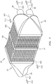
- FIG. 1 shows a heat exchanger 20 providing heat exchange between a first flowpath 600 and a second flowpath 602.
- the flowpaths are gas flowpaths passing respective first and second gas (e.g., air) flows 610 and 612.
- the heat exchanger 20 comprises an inlet manifold 22 and an outlet manifold 24.
- the inlet manifold 22 has one or more inlets (inlet ports) 26 (e.g., a single fitting shown in the example).
- the outlet manifold 24 similarly has one or more outlets (outlet ports) 28 (e.g., two outlet fittings shown in the example).
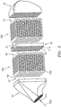
- the heat exchanger 20 has a plurality of plate banks (two plate banks 30A, 30B shown in the example). Along the first flowpath 600 ( FIG. 3 ), each plate bank extends from an upstream first end 32 to a downstream second end 34.
- the plate banks, along the second flowpath 602, extend from an upstream end 36 ( FIG. 2 ) to a downstream end 38. As is discussed further below, the exemplary plate banks are positioned end-to-end along the first flowpath 600.
- One or more docks 50 ( FIG. 3 ) each couple adjacent ends of adjacent plate banks.
- Each of the example plate banks 30A, 30B has a plurality of conduits with interiors along respective branches of the first flowpath 600.
- each conduit is formed by a single separately-formed plate 60 ( FIG. 4 ).
- the banks are formed by a linear array of individual plates as if a stack (but not directly contacting each other).
- Alternative plate banks may include integral groups (e.g., unitarily cast) of plates.
- the plates are only mechanically interconnected via the mating dock(s) and, if a terminal bank, the associated manifold, there are other configurations where the plates may have direct contact (e.g., as in a true stack) and/or direct or other indirect coupling of plates within a given bank.
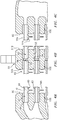
- FIGs. 4A-4C show each plate 60 as having an interior 62 along the respective branch of the first flowpath 600.
- Each plate 60 and a main body portion 63 thereof extends from an upstream end 64 to a downstream end 66 and has an interior surface 68 and an exterior surface 70.
- Each plate 60 and exterior surface 70 has a first face 72A and a second face 72B.
- the exterior surface 70 bears heat transfer fins 74A, 74B ( FIG. 4 ) along the first and second faces 72A, 72B, respectively.
- the fins 74A, 74B are out of phase with each other so that the adjacent plates interdigitate first fins and second fins with the second fins of one plate interdigitating with the first fins of the plate, if any, to the second side thereof.
- the plates also have respective first and second edges 76A, 76B ( FIG. 3 ).
- the docks 50 each have a first face 51A and a second face 51B ( FIG. 4B ). Along each of the first and second faces, the dock has a plurality of sockets 52 ( FIG. 3 ). Exemplary sockets 52 are obround in planform/footprint (e.g., two straight sides and two arcuate (e.g., semicircular) ends). The exemplary sockets 52 have a sidewall 53 ( FIG. 5 ) and a base 54. The base 54 is formed by a shoulder. Each socket on the first face 51A is aligned with a corresponding socket on the second face 51B with an aperture 55 joining the respective bases 54.
- FIG. 4B shows adjacent end portions of adjacent plates of the two banks in the adjacent sockets.
- the manifolds 22, 24 have faces 80 ( FIG. 4A ) and 82 ( FIG. 4C ) each with a similar array of sockets receiving the opposite end portions of the two plate banks.
- both banks are terminal banks.
- Exemplary materials for the manifolds, plate banks, and dock(s) are alloys.
- Exemplary alloys are nickel-based superalloys.
- Exemplary component manufacture is casting.
- Alternative manufacture is additive manufacture (e.g., selective laser sintering or direct metal laser sintering).
- Finish machining e.g., milling and/or abrasive grinding
- a pure machining e.g., from billet or thick plate stock
- An exemplary nickel-based superalloy is the Mar-M family such as Mar-M-247, (nominal weight percent composition: Al 5.4 - 5.7; Cr 8.0 - 8.5; Mn 0.10; Si 0.25; W 9.3 - 9.7; C 0.00 - 0.09; Co 9.0-9.5; Ni, balance, with minor amounts, if any Ta, Ti, Hf, plus impurities, if any). More broadly, the nickel-based superalloys may have nickel as a largest individual by weight and/or atomic elemental content, typically at least 45% by weight, often in the range of 50% to 75% by weight). Exemplary assembly techniques include brazing and diffusion bonding. FIGs. 4A-C show respective joints 100 formed as brazes or diffusion bonds.
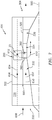
- FIG. 6 shows a heat exchanger 300 which may be otherwise similar to the heat exchanger 20 except that the dock 302 has faces 51A, 51B off-parallel by an angle ⁇ .
- An exemplary angle ⁇ is at least 5° (e.g. 5° to 20°).
- An alternative variation retains the faces 51A, 51B parallel but angles the sockets of one or both sides off-perpendicular to the associated face.
- the bank could form a non-right parallelepiped (vs. the generally right parallelepiped banks of FIGs. 1-6 ).
- FIG. 5 shows one such exemplary mounting feature 200 as an apertured mounting ear (the aperture may receive a bolt, screw, hook, clevis pin, or the like).
- Alternative mounting features include, without limitation, clevises, bosses (e.g., threaded) bearing eyelets, and the like.
- alternative load-bearing joints to the exemplary braze or diffusion bond include dovetail arrangements.
- the plate ends form dovetail projections and the dock sockets form complementary dovetail slots.
- One end of each slot may be open at least initially and then closed. In one group of examples, this is merely an assembly aid.
- the plates may be slid into place wherein the dovetail arrangement holds them in position. Thereafter, they may be brazed or bonded.
- reverse extraction of the plates may be blocked such as by attaching a removable edge portion of the dock which closes the ends of the dovetail slots.
- tying arrangement (not shown - e.g., tie rods engaging features on the manifolds 22 and 24) to hold the plate banks and dock compressed between the manifolds.
- FIG. 7 schematically shows a gas turbine engine 300 as a turbofan engine having a centerline or central longitudinal axis 500 and extending from an upstream end at an inlet 302 to a downstream end at an outlet 304.
- the exemplary engine schematically includes a core flowpath 650 passing a core flow 652 and a bypass flowpath 654 passing a bypass flow 656.
- the core flow and bypass flow are initially formed by respective portions of a combined inlet airflow 658 divided at a splitter 660.
- a core case or other structure 320 divides the core flowpath 650 from the bypass flowpath 654.
- the bypass flowpath 654 is, in turn, surrounded by an outer case 322 which, depending upon implementation, may be a fan case.
- the engine includes a fan section 330 having one or more fan blade stages, a compressor 332 having one or more sections each having one or more blade stages, a combustor 334 (e.g., annular, can-type, or reverse flow), and a turbine 336 again having one or more sections each having one or more blade stages.
- many so-called two-spool engines have two compressor sections and two turbine sections with each turbine section driving a respective associated compressor section and a lower pressure downstream turbine section also driving the fan (optionally via a gear reduction). Yet other arrangements are possible.
- FIG. 7 shows the heat exchanger 20 positioned in the bypass flowpath 654 so that a portion of the bypass flowpath 654 becomes the second flowpath 602 and a portion of the bypass flow 656 becomes the second airflow 612.
- the exemplary first airflow 610 is drawn from a diffuser case 350 between the compressor 332 and combustor 334 and returned radially inwardly back through the core flowpath 650 via struts 360.
- FIG. 7 also schematically shows the mounting feature 200 mounting the heat exchanger.
- An exemplary mounting is to the outer case 322 via a bolt (not shown) passing through the feature 200 and a complementary feature (not-shown - e.g., a single eyelet or clevis) of the case 322.
- Alternative mounting features may be implemented along the core case 320.
- first, second, and the like in the following claims is for differentiation within the claim only and does not necessarily indicate relative or absolute importance or temporal order. Similarly, the identification in a claim of one element as “first” (or the like) does not preclude such "first” element from identifying an element that is referred to as “second” (or the like) in another claim or in the description.
Landscapes
- Engineering & Computer Science (AREA)
- Mechanical Engineering (AREA)
- General Engineering & Computer Science (AREA)
- Physics & Mathematics (AREA)
- Thermal Sciences (AREA)
- Chemical & Material Sciences (AREA)
- Combustion & Propulsion (AREA)
- Geometry (AREA)
- Heat-Exchange Devices With Radiators And Conduit Assemblies (AREA)
Abstract
Description
- The disclosure relates to gas turbine engine heat exchangers. More particularly, the disclosure relates to air-to-air heat exchangers.
- Examples of gas turbine engine heat exchangers are found in: United States Patent Application Publication
20190170445A1 (the '445 publication), McCaffrey, June 6, 2019, "HIGH TEMPERATURE PLATE FIN HEAT EXCHANGER"; United States Patent Application Publication20190170455A1 (the '455 publication), McCaffrey, June 6, 2019, "HEAT EXCHANGER BELL MOUTH INLET"; and United States Patent Application Publication20190212074A1 (the '074 publication), Lockwood et al., July 11, 2019, "METHOD FOR MANUFACTURING A CURVED HEAT EXCHANGER USING WEDGE SHAPED SEGMENTS", the disclosures of which three publications are incorporated by reference in their entireties herein as if set forth at length. - An exemplary positioning of such a heat exchanger provides for the transfer heat from a flow (heat donor flow) diverted from an engine core flow to a bypass flow (heat recipient flow). For example, air is often diverted from the compressor for purposes such as cooling. However, the act of compression heats the air and reduces its cooling effectiveness. Accordingly, the diverted air may be cooled in the heat exchanger to render it more suitable for cooling or other purposes. One particular example draws the heat donor airflow from a diffuser case downstream of the last compressor stage upstream of the combustor. This donor flow transfers heat to a recipient flow which is a portion of the bypass flow. To this end, the heat exchanger may be positioned within a fan duct or other bypass duct. The cooled donor flow is then returned to the engine core (e.g., radially inward through struts) to pass radially inward of the gas path and then be passed rearward for turbine section cooling including the cooling of turbine blades and vanes.
- One aspect of the invention involves a heat exchanger comprising: an inlet manifold having an inlet port; and an outlet manifold having an outlet port. A first gas flowpath passes from the inlet port to the outlet port. A plurality of plate banks are positioned end-to-end, each plate bank having a plurality of conduits with interiors along respective branches of the first gas flowpath, a second gas flowpath extending across exteriors of the plurality of conduits. One or more docks couple adjacent ends of the plurality of plate banks.
- A further embodiment of any of the foregoing embodiments may additionally and/or alternatively include each plate bank being brazed to at least one dock of the one or more docks.
- A further embodiment of any of the foregoing embodiments may additionally and/or alternatively include each plate bank comprising the associated plurality of conduits each being obround in transverse cross-section; and fins on the exterior of the conduits.
- A further embodiment of any of the foregoing embodiments may additionally and/or alternatively include each plate bank comprising the associated plurality of conduits each being an individual casting.
- A further embodiment of any of the foregoing embodiments may additionally and/or alternatively include each of the one or more castings being of a nickel-based alloy.
- A further embodiment of any of the foregoing embodiments may additionally and/or alternatively include each of the one or more castings having a first face and a second face. The first face and the second face respectively bear first fins and second fins. Adjacent castings interdigitate first fins and second fins with the second fins of one casting interdigitating with the first fins of the casting, if any, to the second side thereof.
- A further embodiment of any of the foregoing embodiments may additionally and/or alternatively include each dock comprising: a first face having a plurality of sockets respectively receiving conduits of a first adjacent said plate bank; and a second face having a plurality of sockets respectively receiving conduits of a second adjacent said plate bank.
- A further embodiment of any of the foregoing embodiments may additionally and/or alternatively include the plurality of sockets of the first face and the plurality of sockets of the second face each being obround in socket footprint.
- A further embodiment of any of the foregoing embodiments may additionally and/or alternatively include at least one of the one or more docks coupling its associated plate banks off-parallel to each other.
- A further embodiment of any of the foregoing embodiments may additionally and/or alternatively include at least one of the one or more docks coupling its associated plate banks off-parallel to each other by 5.0° to 20°.
- A further embodiment of any of the foregoing embodiments may additionally and/or alternatively include each of the one or more docks being an individual casting.
- A further embodiment of any of the foregoing embodiments may additionally and/or alternatively include at least one of the one or more docks bearing means for mounting the heat exchanger to environmental structure.
- A further embodiment of any of the foregoing embodiments may additionally and/or alternatively include the means for mounting comprising an apertured mounting ear.
- A further embodiment of any of the foregoing embodiments may additionally and/or alternatively include a turbine engine including the heat exchanger and further comprising: a core flowpath, the first gas flowpath being a diversion from the core flowpath; and a bypass flowpath, the second flowpath being a portion of the bypass flowpath.
- A further embodiment of any of the foregoing embodiments may additionally and/or alternatively include the turbine engine further comprising a case, wherein a mounting feature on the dock is mounted to the case.
- A further embodiment of any of the foregoing embodiments may additionally and/or alternatively include the first flowpath being diverted from downstream of a compressor of the engine.
- A further embodiment of any of the foregoing embodiments may additionally and/or alternatively include a method for manufacturing the heat exchanger. The method comprising: casting the dock, the plurality of plate banks, the inlet manifold, and the outlet manifold; and securing the dock, the plurality of plate banks, the inlet manifold, and the outlet manifold to each other.
- A further embodiment of any of the foregoing embodiments may additionally and/or alternatively include the securing comprising brazing.
- A further embodiment of any of the foregoing embodiments may additionally and/or alternatively include a method for using the heat exchanger. The method comprising: passing a first gas flow along the first flowpath; and passing a second gas flow along the second flowpath, the second flow receiving heat from the first flow.
- A further embodiment of any of the foregoing embodiments may additionally and/or alternatively include: the first flow being a diversion of a core flow of a turbine engine; and the second flow being a portion of a bypass flow of the turbine engine.
- The details of one or more embodiments are set forth in the accompanying drawings and the description below. Other features, objects, and advantages will be apparent from the description and drawings, and from the claims.
-
-
FIG. 1 is a first view of a heat exchanger. -
FIG. 2 is a second view of the heat exchanger. -
FIG. 3 is an exploded view of the heat exchanger. -
FIG. 4 is a cross-sectional view of the heat exchanger taken along line 4-4 ofFIG. 2 . -
FIG. 4A is an enlarged view of an inlet manifold downstream end of the heat exchanger ofFIG. 4 . -
FIG. 4B is an enlarged view of a dock of the heat exchanger ofFIG. 4 . -
FIG. 4C is an enlarged view of an outlet manifold upstream end of the heat exchanger ofFIG. 4 . -
FIG. 5 is a plan view of the dock of the heat exchanger. -
FIG. 6 is a sectional view of an alternate heat exchanger having an angled dock. -
FIG. 7 is a partially schematic half view of an engine with heat exchanger. - Like reference numbers and designations in the various drawings indicate like elements.
-
FIG. 1 shows aheat exchanger 20 providing heat exchange between afirst flowpath 600 and asecond flowpath 602. In the exemplary embodiment, the flowpaths are gas flowpaths passing respective first and second gas (e.g., air) flows 610 and 612. - The
heat exchanger 20 comprises aninlet manifold 22 and anoutlet manifold 24. Along thefirst flowpath 600, theinlet manifold 22 has one or more inlets (inlet ports) 26 (e.g., a single fitting shown in the example). Theoutlet manifold 24 similarly has one or more outlets (outlet ports) 28 (e.g., two outlet fittings shown in the example). - As is discussed further below, the
heat exchanger 20 has a plurality of plate banks (twoplate banks FIG. 3 ), each plate bank extends from an upstreamfirst end 32 to a downstreamsecond end 34. - The plate banks, along the
second flowpath 602, extend from an upstream end 36 (FIG. 2 ) to adownstream end 38. As is discussed further below, the exemplary plate banks are positioned end-to-end along thefirst flowpath 600. One or more docks 50 (FIG. 3 ) each couple adjacent ends of adjacent plate banks. - Each of the
example plate banks first flowpath 600. In the example plate banks, each conduit is formed by a single separately-formed plate 60 (FIG. 4 ). In the example plate banks, the banks are formed by a linear array of individual plates as if a stack (but not directly contacting each other). Alternative plate banks may include integral groups (e.g., unitarily cast) of plates. Although in the example plate banks, the plates are only mechanically interconnected via the mating dock(s) and, if a terminal bank, the associated manifold, there are other configurations where the plates may have direct contact (e.g., as in a true stack) and/or direct or other indirect coupling of plates within a given bank. -
FIGs. 4A-4C show eachplate 60 as having an interior 62 along the respective branch of thefirst flowpath 600. Eachplate 60 and amain body portion 63 thereof extends from anupstream end 64 to adownstream end 66 and has aninterior surface 68 and anexterior surface 70. Eachplate 60 andexterior surface 70 has afirst face 72A and asecond face 72B. Theexterior surface 70 bears heattransfer fins FIG. 4 ) along the first andsecond faces fins second edges FIG. 3 ). - The
docks 50 each have afirst face 51A and asecond face 51B (FIG. 4B ). Along each of the first and second faces, the dock has a plurality of sockets 52 (FIG. 3 ).Exemplary sockets 52 are obround in planform/footprint (e.g., two straight sides and two arcuate (e.g., semicircular) ends). Theexemplary sockets 52 have a sidewall 53 (FIG. 5 ) and abase 54. Thebase 54 is formed by a shoulder. Each socket on thefirst face 51A is aligned with a corresponding socket on thesecond face 51B with anaperture 55 joining the respective bases 54.FIG. 4B shows adjacent end portions of adjacent plates of the two banks in the adjacent sockets. Themanifolds FIG. 4A ) and 82 (FIG. 4C ) each with a similar array of sockets receiving the opposite end portions of the two plate banks. In an exemplary two-bank implementation, both banks are terminal banks. In an alternative implementation with three or more banks, there would be one fewer docks than banks and the two terminal banks would mount to the manifolds. - Exemplary materials for the manifolds, plate banks, and dock(s) are alloys. Exemplary alloys are nickel-based superalloys. Exemplary component manufacture is casting. Alternative manufacture is additive manufacture (e.g., selective laser sintering or direct metal laser sintering). Finish machining (e.g., milling and/or abrasive grinding) may true up mating surfaces. Particularly for the dock, a pure machining (e.g., from billet or thick plate stock) is possible. An exemplary nickel-based superalloy is the Mar-M family such as Mar-M-247, (nominal weight percent composition: Al 5.4 - 5.7; Cr 8.0 - 8.5; Mn 0.10; Si 0.25; W 9.3 - 9.7; C 0.00 - 0.09; Co 9.0-9.5; Ni, balance, with minor amounts, if any Ta, Ti, Hf, plus impurities, if any). More broadly, the nickel-based superalloys may have nickel as a largest individual by weight and/or atomic elemental content, typically at least 45% by weight, often in the range of 50% to 75% by weight). Exemplary assembly techniques include brazing and diffusion bonding.
FIGs. 4A-C showrespective joints 100 formed as brazes or diffusion bonds. - Among further variations are angling the plate banks off parallel to each other.
FIG. 6 shows aheat exchanger 300 which may be otherwise similar to theheat exchanger 20 except that thedock 302 hasfaces faces FIGs. 1-6 ). - Among further variations are integration of one or more of several types of features with the dock. These may include mounting features for mounting the heat exchanger to environmental structure and/or mounting features for mounting additional components to the heat exchanger.
FIG. 5 shows one suchexemplary mounting feature 200 as an apertured mounting ear (the aperture may receive a bolt, screw, hook, clevis pin, or the like). Alternative mounting features include, without limitation, clevises, bosses (e.g., threaded) bearing eyelets, and the like. - Among further variations are differing mating arrangements between the blocks and the dock and/or the manifolds. For example, alternative load-bearing joints to the exemplary braze or diffusion bond include dovetail arrangements. In an exemplary dovetail arrangement (not shown) the plate ends form dovetail projections and the dock sockets form complementary dovetail slots. One end of each slot may be open at least initially and then closed. In one group of examples, this is merely an assembly aid. For example, the plates may be slid into place wherein the dovetail arrangement holds them in position. Thereafter, they may be brazed or bonded. In other variations, reverse extraction of the plates may be blocked such as by attaching a removable edge portion of the dock which closes the ends of the dovetail slots.
- In yet other variations of mating arrangements, alternatively or in addition to the braze or bond, there may be a tying arrangement (not shown - e.g., tie rods engaging features on the
manifolds 22 and 24) to hold the plate banks and dock compressed between the manifolds. -
FIG. 7 schematically shows agas turbine engine 300 as a turbofan engine having a centerline or centrallongitudinal axis 500 and extending from an upstream end at aninlet 302 to a downstream end at anoutlet 304. The exemplary engine schematically includes acore flowpath 650 passing acore flow 652 and abypass flowpath 654 passing abypass flow 656. The core flow and bypass flow are initially formed by respective portions of a combinedinlet airflow 658 divided at asplitter 660. - A core case or
other structure 320 divides thecore flowpath 650 from thebypass flowpath 654. Thebypass flowpath 654 is, in turn, surrounded by anouter case 322 which, depending upon implementation, may be a fan case. From upstream to downstream, the engine includes afan section 330 having one or more fan blade stages, acompressor 332 having one or more sections each having one or more blade stages, a combustor 334 (e.g., annular, can-type, or reverse flow), and aturbine 336 again having one or more sections each having one or more blade stages. For example, many so-called two-spool engines have two compressor sections and two turbine sections with each turbine section driving a respective associated compressor section and a lower pressure downstream turbine section also driving the fan (optionally via a gear reduction). Yet other arrangements are possible. -
FIG. 7 shows theheat exchanger 20 positioned in thebypass flowpath 654 so that a portion of thebypass flowpath 654 becomes thesecond flowpath 602 and a portion of thebypass flow 656 becomes thesecond airflow 612. - The exemplary
first airflow 610 is drawn from adiffuser case 350 between thecompressor 332 andcombustor 334 and returned radially inwardly back through thecore flowpath 650 viastruts 360. -
FIG. 7 also schematically shows the mountingfeature 200 mounting the heat exchanger. An exemplary mounting is to theouter case 322 via a bolt (not shown) passing through thefeature 200 and a complementary feature (not-shown - e.g., a single eyelet or clevis) of thecase 322. Alternative mounting features may be implemented along thecore case 320. - The use of "first", "second", and the like in the following claims is for differentiation within the claim only and does not necessarily indicate relative or absolute importance or temporal order. Similarly, the identification in a claim of one element as "first" (or the like) does not preclude such "first" element from identifying an element that is referred to as "second" (or the like) in another claim or in the description.
- One or more embodiments have been described. Nevertheless, it will be understood that various modifications may be made. For example, when applied to an existing baseline engine or baseline heat exchanger configuration, details of such baseline may influence details of particular implementations. Accordingly, other embodiments are within the scope of the following claims.
Claims (15)
- A heat exchanger (20) comprising:an inlet manifold (22) having an inlet port (26);an outlet manifold (24) having an outlet port (28), a first gas flowpath (600) passing from the inlet port (26) to the outlet port (28);a plurality of plate banks (30) positioned end-to-end, each plate bank (30) having a plurality of conduits with interiors along respective branches of the first gas flowpath (600), a second gas flowpath (602) extending across exteriors of the plurality of conduits; andone or more docks (50) coupling adjacent ends of the plurality of plate banks (30).
- The heat exchanger (20) of claim 1, wherein each plate bank (30) is brazed to at least one dock of the one or more docks (50).
- The heat exchanger (20) of claim 1 or 2, wherein each plate bank (30) comprises:
the associated plurality of conduits each being obround in transverse cross-section; and fins on the exterior of the conduits. - The heat exchanger (20) of claim 1, 2 or 3, wherein each plate bank (30) comprises:
the associated plurality of conduits each being an individual casting, wherein each of the one or more castings is optionally of a nickel-based alloy. - The heat exchanger (20) of claim 4, wherein:each of the one or more castings has a first face and a second face;the first face and the second face respectively bear first fins and second fins; andadjacent castings interdigitate first fins and second fins with the second fins of one casting interdigitating with the first fins of the casting, if any, to the second side thereof.
- The heat exchanger (20) of any preceding claim, wherein each dock (50) comprises:a first face (51A) having a plurality of sockets (52) respectively receiving conduits of a first adjacent said plate bank; anda second face (51B) having a plurality of sockets (52) respectively receiving conduits of a second adjacent said plate bank.
- The heat exchanger (20) of claim 6 wherein:
the plurality of sockets (52) of the first face (51A) and the plurality of sockets (52) of the second face (51B) are each obround in socket footprint. - The heat exchanger (20) of any preceding claim, wherein:
at least one of the one or more docks (50) couples its associated plate banks (30) off-parallel to each other, wherein at least one of the one or more docks (50) optionally couples its associated plate banks (30) off-parallel to each other by 5.0° to 20°. - The heat exchanger (20) of any preceding claim, wherein:
each of the one or more docks (50) is an individual casting. - The heat exchanger (20) of any preceding claim, wherein:
at least one of the one or more docks (50) bears means for mounting the heat exchanger (20) to environmental structure, wherein:
the means for mounting optionally comprises an apertured mounting ear (200). - A turbine engine (300) including the heat exchanger (20) of any preceding claim, and further comprising:a core flowpath (650), the first gas flowpath (600) being a diversion from the core flowpath (650); anda bypass flowpath (654), the second flowpath (602) being a portion of the bypass flowpath (654).
- The turbine engine (300) of claim 11 further comprising a case (322) and wherein:
a mounting feature (200) on the dock (50) is mounted to the case (322). - The turbine engine (300) of claim 11 or 12 wherein:
the first flowpath (600) is diverted from downstream of a compressor (332) of the engine (300). - A method for manufacturing the heat exchanger (20) of any of claims 1-10, the method comprising:casting the dock (50), the plurality of plate banks (30), the inlet manifold (22), and the outlet manifold (24); andsecuring the dock (50), the plurality of plate banks (30), the inlet manifold (22), and the outlet manifold (24) to each other, wherein the securing optionally comprises brazing.
- A method for using the heat exchanger (20) of any of claims 1-10, the method comprising:passing a first gas flow (610) along the first flowpath (600); andpassing a second gas flow (612) along the second flowpath (602), the second flow (612) receiving heat from the first flow (610), wherein optionally:the first flow (610) is a diversion of a core flow (652) of a turbine engine (300); andthe second flow (612) is a portion of a bypass flow (656) of the turbine engine (300).
Applications Claiming Priority (1)
| Application Number | Priority Date | Filing Date | Title |
|---|---|---|---|
| US16/685,483 US20210148638A1 (en) | 2019-11-15 | 2019-11-15 | Aircraft Heat Exchanger Assembly |
Publications (1)
| Publication Number | Publication Date |
|---|---|
| EP3822571A1 true EP3822571A1 (en) | 2021-05-19 |
Family
ID=73401461
Family Applications (1)
| Application Number | Title | Priority Date | Filing Date |
|---|---|---|---|
| EP20207313.6A Withdrawn EP3822571A1 (en) | 2019-11-15 | 2020-11-12 | Aircraft heat exchanger assembly |
Country Status (2)
| Country | Link |
|---|---|
| US (1) | US20210148638A1 (en) |
| EP (1) | EP3822571A1 (en) |
Cited By (3)
| Publication number | Priority date | Publication date | Assignee | Title |
|---|---|---|---|---|
| EP4438874A1 (en) * | 2023-03-28 | 2024-10-02 | Sumitomo Precision Products Co., Ltd. | Method for manufacturing heat exchanger and heat exchanger |
| FR3158309A1 (en) * | 2024-01-11 | 2025-07-18 | Airbus Operations | THERMAL ASSEMBLY FOR AN AIRCRAFT PROPULSION SYSTEM |
| FR3159663A1 (en) * | 2024-02-26 | 2025-08-29 | Liebherr-Aerospace Toulouse Sas | HEAT EXCHANGER COMPRISING A PLURALITY OF FLUID CIRCULATION PLATES EACH COMPRISING AT LEAST TWO DISTINCT PORTIONS, COOLING SYSTEM AND METHOD OF MANUFACTURING |
Families Citing this family (5)
| Publication number | Priority date | Publication date | Assignee | Title |
|---|---|---|---|---|
| US11525637B2 (en) * | 2020-01-19 | 2022-12-13 | Raytheon Technologies Corporation | Aircraft heat exchanger finned plate manufacture |
| US20220106046A1 (en) * | 2020-10-06 | 2022-04-07 | Honeywell International Inc. | Pressure containment component for aircraft systems |
| US12044488B2 (en) | 2021-10-01 | 2024-07-23 | Hamilton Sundstrand Corporation | Interlocking dovetail geometry joint |
| US12372313B2 (en) * | 2022-12-15 | 2025-07-29 | Rtx Corporation | Variable passages to optimize delta p and heat transfer along flow path |
| US12578145B2 (en) * | 2023-08-22 | 2026-03-17 | Hamilton Sundstrand Corporation | Heat exchanger core geometries used as support material and fluid connectivity passages for heat exchanger headering |
Citations (7)
| Publication number | Priority date | Publication date | Assignee | Title |
|---|---|---|---|---|
| US2984456A (en) * | 1959-03-12 | 1961-05-16 | Young Radiator Co | Baffle for opposed engine cooling radiator cores |
| US7234511B1 (en) * | 1995-06-13 | 2007-06-26 | Philip George Lesage | Modular heat exchanger having a brazed core and method for forming |
| EP3364142A1 (en) * | 2017-02-17 | 2018-08-22 | HS Marston Aerospace Limited | Heat transfer segment |
| US20190170455A1 (en) | 2017-12-01 | 2019-06-06 | United Technologies Corporation | Heat exchanger bell mouth inlet |
| US20190170445A1 (en) | 2017-12-01 | 2019-06-06 | United Technologies Corporation | High temperature plate fin heat exchanger |
| US20190212074A1 (en) | 2018-01-08 | 2019-07-11 | Hamilton Sundstrand Corporation | Method for manufacturing a curved heat exchanger using wedge shaped segments |
| EP3537085A1 (en) * | 2018-03-07 | 2019-09-11 | United Technologies Corporation | Ganged plate stack in cast plate fin heat exchanger |
-
2019
- 2019-11-15 US US16/685,483 patent/US20210148638A1/en not_active Abandoned
-
2020
- 2020-11-12 EP EP20207313.6A patent/EP3822571A1/en not_active Withdrawn
Patent Citations (7)
| Publication number | Priority date | Publication date | Assignee | Title |
|---|---|---|---|---|
| US2984456A (en) * | 1959-03-12 | 1961-05-16 | Young Radiator Co | Baffle for opposed engine cooling radiator cores |
| US7234511B1 (en) * | 1995-06-13 | 2007-06-26 | Philip George Lesage | Modular heat exchanger having a brazed core and method for forming |
| EP3364142A1 (en) * | 2017-02-17 | 2018-08-22 | HS Marston Aerospace Limited | Heat transfer segment |
| US20190170455A1 (en) | 2017-12-01 | 2019-06-06 | United Technologies Corporation | Heat exchanger bell mouth inlet |
| US20190170445A1 (en) | 2017-12-01 | 2019-06-06 | United Technologies Corporation | High temperature plate fin heat exchanger |
| US20190212074A1 (en) | 2018-01-08 | 2019-07-11 | Hamilton Sundstrand Corporation | Method for manufacturing a curved heat exchanger using wedge shaped segments |
| EP3537085A1 (en) * | 2018-03-07 | 2019-09-11 | United Technologies Corporation | Ganged plate stack in cast plate fin heat exchanger |
Cited By (4)
| Publication number | Priority date | Publication date | Assignee | Title |
|---|---|---|---|---|
| EP4438874A1 (en) * | 2023-03-28 | 2024-10-02 | Sumitomo Precision Products Co., Ltd. | Method for manufacturing heat exchanger and heat exchanger |
| FR3158309A1 (en) * | 2024-01-11 | 2025-07-18 | Airbus Operations | THERMAL ASSEMBLY FOR AN AIRCRAFT PROPULSION SYSTEM |
| FR3159663A1 (en) * | 2024-02-26 | 2025-08-29 | Liebherr-Aerospace Toulouse Sas | HEAT EXCHANGER COMPRISING A PLURALITY OF FLUID CIRCULATION PLATES EACH COMPRISING AT LEAST TWO DISTINCT PORTIONS, COOLING SYSTEM AND METHOD OF MANUFACTURING |
| WO2025180698A1 (en) * | 2024-02-26 | 2025-09-04 | Liebherr-Aerospace Toulouse Sas | Heat exchanger comprising a plurality of fluid circulation plates each comprising at least two separate portions, cooling system and manufacturing method |
Also Published As
| Publication number | Publication date |
|---|---|
| US20210148638A1 (en) | 2021-05-20 |
Similar Documents
| Publication | Publication Date | Title |
|---|---|---|
| EP3822571A1 (en) | Aircraft heat exchanger assembly | |
| US11885573B2 (en) | Aircraft heat exchanger panel attachment | |
| US11920517B2 (en) | Aircraft bypass duct heat exchanger | |
| US12140077B2 (en) | Aircraft heat exchanger assembly | |
| US11835304B2 (en) | Heat exchanger with stacked flow channel modules | |
| US11982232B2 (en) | Aircraft heat exchangers | |
| US8496443B2 (en) | Modular turbine airfoil and platform assembly with independent root teeth | |
| US20230055470A1 (en) | Aircraft Heat Exchanger Finned Plate Manufacture | |
| EP3911908B1 (en) | Aircraft heat exchanger | |
| US20100115967A1 (en) | Eccentric chamfer at inlet of branches in a flow channel | |
| EP4737843A2 (en) | Aircraft heat exchangers and plates | |
| EP3284907B1 (en) | Multi-wall blade with cooled platform | |
| EP3184738A1 (en) | Cooling circuit for a multi-wall blade | |
| EP4089273B1 (en) | Heat exchanger tube support | |
| US12442597B2 (en) | Heat exchanger with progressive divided flow circuit, structural load bearing design | |
| US20250075986A1 (en) | Heat exchangers with modular cores and methods of making the same | |
| EP4023990B1 (en) | A tube for a heat exchanger |
Legal Events
| Date | Code | Title | Description |
|---|---|---|---|
| PUAI | Public reference made under article 153(3) epc to a published international application that has entered the european phase |
Free format text: ORIGINAL CODE: 0009012 |
|
| STAA | Information on the status of an ep patent application or granted ep patent |
Free format text: STATUS: THE APPLICATION HAS BEEN PUBLISHED |
|
| AK | Designated contracting states |
Kind code of ref document: A1 Designated state(s): AL AT BE BG CH CY CZ DE DK EE ES FI FR GB GR HR HU IE IS IT LI LT LU LV MC MK MT NL NO PL PT RO RS SE SI SK SM TR |
|
| STAA | Information on the status of an ep patent application or granted ep patent |
Free format text: STATUS: REQUEST FOR EXAMINATION WAS MADE |
|
| 17P | Request for examination filed |
Effective date: 20211111 |
|
| RBV | Designated contracting states (corrected) |
Designated state(s): AL AT BE BG CH CY CZ DE DK EE ES FI FR GB GR HR HU IE IS IT LI LT LU LV MC MK MT NL NO PL PT RO RS SE SI SK SM TR |
|
| STAA | Information on the status of an ep patent application or granted ep patent |
Free format text: STATUS: EXAMINATION IS IN PROGRESS |
|
| 17Q | First examination report despatched |
Effective date: 20230309 |
|
| RAP3 | Party data changed (applicant data changed or rights of an application transferred) |
Owner name: RTX CORPORATION |
|
| STAA | Information on the status of an ep patent application or granted ep patent |
Free format text: STATUS: THE APPLICATION IS DEEMED TO BE WITHDRAWN |
|
| 18D | Application deemed to be withdrawn |
Effective date: 20230720 |