EP3822552B1 - Exhaust fan assembly having a system for automatically opening a damper in the event of a power failure - Google Patents
Exhaust fan assembly having a system for automatically opening a damper in the event of a power failure Download PDFInfo
- Publication number
- EP3822552B1 EP3822552B1 EP20204730.4A EP20204730A EP3822552B1 EP 3822552 B1 EP3822552 B1 EP 3822552B1 EP 20204730 A EP20204730 A EP 20204730A EP 3822552 B1 EP3822552 B1 EP 3822552B1
- Authority
- EP
- European Patent Office
- Prior art keywords
- pivot arm
- damper
- fan
- pivot
- exhaust fan
- Prior art date
- Legal status (The legal status is an assumption and is not a legal conclusion. Google has not performed a legal analysis and makes no representation as to the accuracy of the status listed.)
- Active
Links
Images


Classifications
-
- F—MECHANICAL ENGINEERING; LIGHTING; HEATING; WEAPONS; BLASTING
- F24—HEATING; RANGES; VENTILATING
- F24F—AIR-CONDITIONING; AIR-HUMIDIFICATION; VENTILATION; USE OF AIR CURRENTS FOR SCREENING
- F24F13/00—Details common to, or for air-conditioning, air-humidification, ventilation or use of air currents for screening
- F24F13/08—Air-flow control members, e.g. louvres, grilles, flaps or guide plates
- F24F13/10—Air-flow control members, e.g. louvres, grilles, flaps or guide plates movable, e.g. dampers
- F24F13/14—Air-flow control members, e.g. louvres, grilles, flaps or guide plates movable, e.g. dampers built up of tilting members, e.g. louvre
- F24F13/1426—Air-flow control members, e.g. louvres, grilles, flaps or guide plates movable, e.g. dampers built up of tilting members, e.g. louvre characterised by actuating means
-
- F—MECHANICAL ENGINEERING; LIGHTING; HEATING; WEAPONS; BLASTING
- F04—POSITIVE - DISPLACEMENT MACHINES FOR LIQUIDS; PUMPS FOR LIQUIDS OR ELASTIC FLUIDS
- F04D—NON-POSITIVE-DISPLACEMENT PUMPS
- F04D25/00—Pumping installations or systems
- F04D25/02—Units comprising pumps and their driving means
- F04D25/06—Units comprising pumps and their driving means the pump being electrically driven
-
- F—MECHANICAL ENGINEERING; LIGHTING; HEATING; WEAPONS; BLASTING
- F04—POSITIVE - DISPLACEMENT MACHINES FOR LIQUIDS; PUMPS FOR LIQUIDS OR ELASTIC FLUIDS
- F04D—NON-POSITIVE-DISPLACEMENT PUMPS
- F04D29/00—Details, component parts, or accessories
- F04D29/40—Casings; Connections of working fluid
-
- F—MECHANICAL ENGINEERING; LIGHTING; HEATING; WEAPONS; BLASTING
- F24—HEATING; RANGES; VENTILATING
- F24F—AIR-CONDITIONING; AIR-HUMIDIFICATION; VENTILATION; USE OF AIR CURRENTS FOR SCREENING
- F24F11/00—Control or safety arrangements
- F24F11/30—Control or safety arrangements for purposes related to the operation of the system, e.g. for safety or monitoring
- F24F11/32—Responding to malfunctions or emergencies
- F24F11/33—Responding to malfunctions or emergencies to fire, excessive heat or smoke
- F24F11/34—Responding to malfunctions or emergencies to fire, excessive heat or smoke by opening air passages
-
- F—MECHANICAL ENGINEERING; LIGHTING; HEATING; WEAPONS; BLASTING
- F24—HEATING; RANGES; VENTILATING
- F24F—AIR-CONDITIONING; AIR-HUMIDIFICATION; VENTILATION; USE OF AIR CURRENTS FOR SCREENING
- F24F13/00—Details common to, or for air-conditioning, air-humidification, ventilation or use of air currents for screening
- F24F13/08—Air-flow control members, e.g. louvres, grilles, flaps or guide plates
- F24F13/10—Air-flow control members, e.g. louvres, grilles, flaps or guide plates movable, e.g. dampers
- F24F13/14—Air-flow control members, e.g. louvres, grilles, flaps or guide plates movable, e.g. dampers built up of tilting members, e.g. louvre
- F24F13/1486—Air-flow control members, e.g. louvres, grilles, flaps or guide plates movable, e.g. dampers built up of tilting members, e.g. louvre characterised by bearings, pivots or hinges
-
- F—MECHANICAL ENGINEERING; LIGHTING; HEATING; WEAPONS; BLASTING
- F24—HEATING; RANGES; VENTILATING
- F24F—AIR-CONDITIONING; AIR-HUMIDIFICATION; VENTILATION; USE OF AIR CURRENTS FOR SCREENING
- F24F7/00—Ventilation
- F24F7/02—Roof ventilation
- F24F7/025—Roof ventilation with forced air circulation by means of a built-in ventilator
-
- F—MECHANICAL ENGINEERING; LIGHTING; HEATING; WEAPONS; BLASTING
- F24—HEATING; RANGES; VENTILATING
- F24F—AIR-CONDITIONING; AIR-HUMIDIFICATION; VENTILATION; USE OF AIR CURRENTS FOR SCREENING
- F24F13/00—Details common to, or for air-conditioning, air-humidification, ventilation or use of air currents for screening
- F24F13/08—Air-flow control members, e.g. louvres, grilles, flaps or guide plates
- F24F13/10—Air-flow control members, e.g. louvres, grilles, flaps or guide plates movable, e.g. dampers
- F24F13/14—Air-flow control members, e.g. louvres, grilles, flaps or guide plates movable, e.g. dampers built up of tilting members, e.g. louvre
- F24F13/1426—Air-flow control members, e.g. louvres, grilles, flaps or guide plates movable, e.g. dampers built up of tilting members, e.g. louvre characterised by actuating means
- F24F2013/1453—Air-flow control members, e.g. louvres, grilles, flaps or guide plates movable, e.g. dampers built up of tilting members, e.g. louvre characterised by actuating means with cables, e.g. bowden cables
-
- F—MECHANICAL ENGINEERING; LIGHTING; HEATING; WEAPONS; BLASTING
- F24—HEATING; RANGES; VENTILATING
- F24F—AIR-CONDITIONING; AIR-HUMIDIFICATION; VENTILATION; USE OF AIR CURRENTS FOR SCREENING
- F24F13/00—Details common to, or for air-conditioning, air-humidification, ventilation or use of air currents for screening
- F24F13/08—Air-flow control members, e.g. louvres, grilles, flaps or guide plates
- F24F13/10—Air-flow control members, e.g. louvres, grilles, flaps or guide plates movable, e.g. dampers
- F24F13/14—Air-flow control members, e.g. louvres, grilles, flaps or guide plates movable, e.g. dampers built up of tilting members, e.g. louvre
- F24F13/1426—Air-flow control members, e.g. louvres, grilles, flaps or guide plates movable, e.g. dampers built up of tilting members, e.g. louvre characterised by actuating means
- F24F2013/146—Air-flow control members, e.g. louvres, grilles, flaps or guide plates movable, e.g. dampers built up of tilting members, e.g. louvre characterised by actuating means with springs
-
- F—MECHANICAL ENGINEERING; LIGHTING; HEATING; WEAPONS; BLASTING
- F24—HEATING; RANGES; VENTILATING
- F24F—AIR-CONDITIONING; AIR-HUMIDIFICATION; VENTILATION; USE OF AIR CURRENTS FOR SCREENING
- F24F2140/00—Control inputs relating to system states
- F24F2140/40—Damper positions, e.g. open or closed
Definitions
- the present invention relates to exhaust fans employed to exhaust air from a building, and more particularly to a system and process employed in exhaust fans for opening one or more dampers of the exhaust fan in the event of a power failure.
- Exhaust fans are employed to exhaust air from buildings. They typically include a fan driven by an electric motor. Further, they typically include one or more dampers that are open by the force of air being induced upwardly through the exhaust fan. Thus if there is a power failure, the motor fails to drive the fan and the dampers remain closed. Yet in the case of a commercial kitchen, for example, hot air is still produced and tends to accumulate in the exhaust fan due to the dampers being closed. Thus, it can get extremely hot in and around the motor and this can damage the motor and at the same time present a fire hazard.
- Utility model publication DE 20 2005 010 625 U1 describes a ventilator for removing smoke and heat from buildings, the ventilator having a flap which is opened by a gas spring and closed by a cable which is wound on to a reel by an electric motor.
- the present invention entails a rooftop exhaust fan as set out in accompanying claim 1.
- the pivot arm includes a remote end opposite a pivot end.
- a latching bracket Secured to the housing of the exhaust fan is a latching bracket.
- the remote end of the pivot arm includes a latch that is connectable to the latching bracket.
- an exhaust fan is shown therein and indicated generally by the numeral 10. See Figure 1 .
- the exhaust fan 10 is what is generally referred to as an upblast type. It is understood and appreciated by those skilled in the art that the present invention can easily be employed with a downblast type exhaust fan.
- Exhaust fan 10 can be used for general ventilation or can be used in conjunction with a commercial kitchen to exhaust smoky and grease laden air that emanates from a cooking surface generally disposed underneath a hood.
- Exhaust fan 10 includes a housing indicated generally by the numeral 12. It is appreciated that the specific design and construction of the housing can vary from one application to another.
- the housing 12 includes an outer housing 12A that can assume a generally rectangular or square form or other forms.
- Housing 12 further includes an upper housing 12B that extends upwardly from the outer housing 12A and functions as an air duct for directing exhaust air upwardly through a portion of the exhaust fan.
- Upper housing 12B is sometimes referred to as an airshaft.
- the upper housing assumes a generally circular form.
- Exhaust fan 10 is provided with means for inducing air to move upwardly through the exhaust fan where the air is exhausted to the atmosphere.
- the housing 12A can be mounted on a curb (not shown) that leads to a duct structure within the building. Hence, in the case of the use of a curb, the exhaust air moves from the building through the curb and then through the exhaust fan 10.
- Various fan and motor arrangements can be incorporated into the exhaust fan 10.
- the exhaust fan includes a propeller 16 which is directly driven by a motor 18. Note that the propeller 16 and motor 18 are axially aligned with the upper circular housing or airshaft 12B. It is appreciated by those skilled in the art that a fan wheel may be used in lieu of the propeller 16.
- the propeller 16 is directly driven by the motor 18. Generally when a direct drive is employed, the propeller 16 is essentially mounted to the drive shaft of the motor 18 or to an extension therefrom. In other cases, the fan wheel or propeller can be driven from a side mounted motor through a belt drive.
- dampers 30 Supported at the outlet end of the upper housing 12B are one or more dampers 30.
- dampers 30 there is provided two dampers 30 with the dampers being pivotally mounted about transverse axes about the top of the upper housing 12B.
- the dampers are supported, at least indirectly, by the upper housing or airshaft 12B.
- the dampers 30 are disposed over the propeller 16 and motor 18. Since the dampers 30 are pivotally mounted, they are moveable from a generally horizontally closed position to a raised or inclined open position. See Figure 1 where one of the dampers 30 assumes the closed position while the other damper assumes the open position.
- a gutter 32 Disposed between the inboard edges of the damper 30 is a gutter 32. Note that the gutter 32 forms a trough between the inboard edges of the dampers 30. Gutter 32 and the dampers 30 are configured such that when the dampers assume the closed position, rainwater will flow from the surface of the dampers into the gutter 32 and be discharged out the side of the fan assembly 10.
- the force of the air being exhausted upwardly through the exhaust fan 10 is sufficient to open the dampers 30 so as to permit the exhaust air to escape.
- the focus of the present invention is to provide an exhaust fan with some means to automatically open the dampers 30 when there is an electricity or motor failure.
- a damper actuator assembly indicated generally by the numeral 40. See Figures 3-6 , for example.
- At the center of the damper actuator assembly 40 is at least one pivot arm indicated generally by the numeral 50. Details of the pivot arm 50 will be discussed subsequently.
- the function of the pivot arm which lies below the dampers 30 is to pivot from a generally horizontal position to a raised position where the pivot arm engages the underside of the dampers and pivots the dampers to an open position.
- FIG. 3-5 Shown here is a pair of latching brackets indicated generally by numeral 42. Each latching bracket is secured to the inner surface of the airshaft 12B. Latching brackets 42 are generally transversely aligned. As shown in Figure 4 , there is a pair of U-shaped pivot supports 44 secured underneath the gutter 32. Supports 44 are secured by rivets or other suitable fastening means to the underside of the gutter 32. Note that the U-shaped pivot supports 44 include outer terminal end portions that are referred to as support fingers 46. See Figures 3 and 4 . Extending between the U-shaped pivot supports 44 and the latching brackets 42 is a series of parallel supports 48. See Figure 3 . In particular there is a pair of parallel supports 48 that extend from opposite sides of the gutter 32 to the latching brackets 42. These parallel supports 48 tend to support the gutter 32.
- pivot arm 50 Two exemplary designs for the pivot arm 50 are shown in the drawings.
- a single pivot arm is used to actuate a damper 30. See Figures 6-8 .
- dual pivot arms are employed to actuate the damper.
- the pivot arm includes a pivot end 50A and a remote end 50B. See Figure 6 .
- Formed in the remote end 50B of the pivot arm 50 are two elongated slots 50C.
- a locking pin 50D is slideably contained in the slots 50C and as will be discussed subsequently herein, the locking pin is used to lock the pivot arm 50 to the latching bracket 42 for purposes of assembly or shipment.
- Pivot arm 50 includes a generally shallow U-shaped channel that includes a series of cutouts formed in a web that forms a part of the pivot arm. Note that the pivot end 50A is pivotally mounted about a pivot pin to respective support fingers 46. Hence pivot arm 50 can pivot back and forth about the pivot axis thereof.
- pivot arm 50 When the two dampers 30 assume a closed position, a pair of pivot arms 50 are disposed underneath the dampers.
- the pivot arms can be slightly spaced below the dampers 30 or can slightly engage the underside of the dampers when the dampers assume the closed position.
- Pivot arm 50 is moveable from a generally horizontal position shown in Figure 8 to a raised position shown in Figure 6 . It is appreciated that as the pivot arm 50 moves from the generally horizontal position to the raised position, it will engage the overlying damper 30 and opens the same.
- Pivot arm 50 is biased to move to the raised position. This is achieved by providing a gas spring piston 52 and connecting the piston between one latching bracket 42 and an intermediate point on the pivot arm.
- the base of the gas spring piston 52 is pivotally connected to a lower portion of the latching bracket 42 while the rod end is connected to a pivot pin that extends across a cutout formed in the web of the pivot arm.
- the damper actuator assembly 40 includes a mechanical fusible link 54 that is operatively connected between one latching bracket 42 and the pivot arm 50. See Figure 7 .
- the mechanical fusible link 54 is pivotally connected to both the latching bracket 42 and the pivot arm 50. Details of the mechanical fusible link 54 are not dealt with herein because such is not per se material to the present invention and further such mechanical fusible links are well known and appreciated by those skilled in the art.
- a mechanical fusible link is a device that includes two strips of metal soldered together with a fusible alloy that is designed to melt at a specific temperature which allows the two pieces to fracture and separate.
- Mechanical fusible links come in a variety of designs and different temperature ratings. In one exemplary embodiment, it is desirable to select a mechanical fusible link that will break when exposed to a temperature in the range of 347 Kelvin (165°F).
- a gas spring piston is a type of spring that, similar to typical mechanical springs, relies on elastic deformation, and uses compressed gas contained within an enclosed cylinder sealed by a sliding piston to pneumatically store potential energy and withstand at least some external force applied parallel in the direction of the piston. Thus, because the gas spring piston is biased to extend, the force exerted by the piston must be overcome while connecting the mechanical fusible link 54.
- the damper actuator assembly 40 provides a means to lock the pivot arm 50 in the horizontal position. This is achieved by pushing down the pivot arm against the bias of the gas spring piston 52 until the remote end 50B of the pivot arm aligns with a slot 42A formed in the latching bracket 42. Once alignment is achieved, then the locking pin 50D can be slid into the slot 42A and this will lock the pivot arm 50 in the generally horizontal position so that the mechanical fusible link 54 can be easily installed.
- the locked configuration may be maintained while the exhaust fan 10 is being handled or in shipment. However, once the exhaust fan is made operational on a site, the locking pin 50D is retracted from the slot 42A. Now the mechanical fusible link is what holds the pivot arm 50 in the horizontal position.
- the damper actuator includes two pivot arms 50' and 50".
- This design is suited for a situation where the damper 30 is relatively large. Large dampers require more force from the gas spring piston 52 in order to achieve an open status. This in turn impacts the force required to push down the pivot arm in order to connect the mechanical fusible link 54. In some cases, the force is so great that it is difficult, if not impossible, to manually push down the pivot arm 50.
- the embodiment shown in Figures 9 and 10 is provided with two pivot arms 50' and 50" and two gas spring pistons 52' and 52". By pushing each pivot arm down separately, this effectively reduces the force required to push down the pivot arms in half. Yet together they provide sufficient force to open such a relatively large damper.
- pivot arms 50' and 50" are pivotally secured about separate axes.
- One pivot arm 50' is disposed generally over the other pivot arm 50".
- Pivot arms 50' and 50" are provided with means to secure them together.
- a locking bolt 60 is disposed in a slot in pivot arm 50". Locking bolt 60 can slide back and forth in the slot.
- a keyway 62 is provided in the upper pivot arm 50'. This keyway 62 generally overlies the locking bolt 60.
- the lower pivot arm 50" is pushed down and held in the down position until the fusible link or links 54 are secured between the latching bracket 42 and the lower pivot arm.
- the upper pivot arm 50' is pushed down to where it closely overlies the lower pivot arm 50".
- the locking bolt 60 can be extended into the keyway 62 and moved therein to a portion of the keyway that will retain the locking bolt and effectively interlock the pivot arms 50' and 50" together.
- the double pivot arms 50' and 50" function the same as the single pivot arm discussed above and shown in Figures 6-8 .
- a pair of fusible links 54 are employed. This means that both fusible links 54 must be broken through exposure to heat in order for the two pivot arms 50' and 50" to deploy. It is appreciated, however, by those skilled in the art, that one or more fusible links 54 can be employed in any of these embodiments.
- the damper actuator assembly 40 serves an important and useful function when there is a power failure or when the motor 18 fails to operate. When this occurs, there is a significant buildup of heat in the range of 289 Kelvin (62°F) or higher. When this buildup of heat occurs, the mechanical fusible links fail and the damper actuator assembly 40 functions to open the one or more dampers 30 associated with the exhaust fan.
Landscapes
- Engineering & Computer Science (AREA)
- Mechanical Engineering (AREA)
- General Engineering & Computer Science (AREA)
- Chemical & Material Sciences (AREA)
- Combustion & Propulsion (AREA)
- Air-Flow Control Members (AREA)
Description
- The present invention relates to exhaust fans employed to exhaust air from a building, and more particularly to a system and process employed in exhaust fans for opening one or more dampers of the exhaust fan in the event of a power failure.
- Exhaust fans are employed to exhaust air from buildings. They typically include a fan driven by an electric motor. Further, they typically include one or more dampers that are open by the force of air being induced upwardly through the exhaust fan. Thus if there is a power failure, the motor fails to drive the fan and the dampers remain closed. Yet in the case of a commercial kitchen, for example, hot air is still produced and tends to accumulate in the exhaust fan due to the dampers being closed. Thus, it can get extremely hot in and around the motor and this can damage the motor and at the same time present a fire hazard. Utility model publication
DE 20 2005 010 625 U1 describes a ventilator for removing smoke and heat from buildings, the ventilator having a flap which is opened by a gas spring and closed by a cable which is wound on to a reel by an electric motor. - There is a need for a simple and reliable damper control for a building exhaust fan that will automatically open the dampers in response to a buildup of heat in the exhaust fan due to a power or motor failure.
- The present invention entails a rooftop exhaust fan as set out in accompanying claim 1.
- In one embodiment, the pivot arm includes a remote end opposite a pivot end. Secured to the housing of the exhaust fan is a latching bracket. The remote end of the pivot arm includes a latch that is connectable to the latching bracket. By securing the latch to the latching bracket, the pivot arm is held down against the bias of the gas spring piston. This enables the mechanical fusible link to be easily secured to the pivot arm after which the latch is disengaged from the latching bracket.
- Other objects and advantages of the present invention will become apparent and obvious from a study of the following description and the accompanying drawings which are merely illustrative of such invention.
-
-
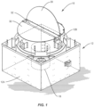
Figure 1 is a perspective view of the exhaust fan assembly. -
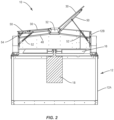
Figure 2 is a side elevational view of the exhaust fan assembly with portions of the housing removed to illustrate the internal structure thereof. -
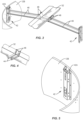
Figure 3 is a fragmentary perspective view showing a portion of a gutter that lies between two dampers. -
Figure 4 is a fragmentary perspective view showing support structure underlying the gutter. -
Figure 5 is a fragmentary perspective view showing a portion of the airshaft and a latching bracket secured to the interior side thereof. -
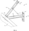
Figure 6 is a fragmentary perspective view showing the damper actuator assembly with the pivot arm disposed in a raised or elevated position. -
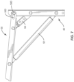
Figure 7 is a fragmentary side elevational view of a portion of the damper actuator assembly and illustrating a mechanical fusible link that holds the pivot arm in a horizontal position. -
Figure 8 is a fragmentary perspective view of a portion of the damper actuator assembly and which shows the mechanical fusible link holding the pivot arm in the normal horizontal position. -
Figure 9 is a fragmentary perspective view showing an alternative design that includes a pair of pivot arms that are employed to open an overlying damper in an emergency situation. -
Figure 10 is a fragmentary perspective view of the embodiment shown inFigure 9 but with the pair of pivot arms being secured and held in their normal horizontal position by the mechanical fusible link. - With further reference to the drawings, an exhaust fan is shown therein and indicated generally by the
numeral 10. SeeFigure 1 . In the embodiment illustrated, theexhaust fan 10 is what is generally referred to as an upblast type. It is understood and appreciated by those skilled in the art that the present invention can easily be employed with a downblast type exhaust fan.Exhaust fan 10 can be used for general ventilation or can be used in conjunction with a commercial kitchen to exhaust smoky and grease laden air that emanates from a cooking surface generally disposed underneath a hood. -
Exhaust fan 10 includes a housing indicated generally by thenumeral 12. It is appreciated that the specific design and construction of the housing can vary from one application to another. In any event, in the embodiment illustrated herein, thehousing 12 includes anouter housing 12A that can assume a generally rectangular or square form or other forms.Housing 12 further includes anupper housing 12B that extends upwardly from theouter housing 12A and functions as an air duct for directing exhaust air upwardly through a portion of the exhaust fan.Upper housing 12B is sometimes referred to as an airshaft. In the embodiment illustrated, the upper housing assumes a generally circular form. -
Exhaust fan 10 is provided with means for inducing air to move upwardly through the exhaust fan where the air is exhausted to the atmosphere. In some applications, thehousing 12A can be mounted on a curb (not shown) that leads to a duct structure within the building. Hence, in the case of the use of a curb, the exhaust air moves from the building through the curb and then through theexhaust fan 10. Various fan and motor arrangements can be incorporated into theexhaust fan 10. In an exemplary embodiment, the exhaust fan includes apropeller 16 which is directly driven by amotor 18. Note that thepropeller 16 andmotor 18 are axially aligned with the upper circular housing orairshaft 12B. It is appreciated by those skilled in the art that a fan wheel may be used in lieu of thepropeller 16. It is understood and appreciated by those skilled in art that other types of fans can be incorporated into theexhaust fan 10. As noted above, in the arrangement shown in the drawings, thepropeller 16 is directly driven by themotor 18. Generally when a direct drive is employed, thepropeller 16 is essentially mounted to the drive shaft of themotor 18 or to an extension therefrom. In other cases, the fan wheel or propeller can be driven from a side mounted motor through a belt drive. - Supported at the outlet end of the
upper housing 12B are one ormore dampers 30. In the embodiment shown herein, there is provided twodampers 30 with the dampers being pivotally mounted about transverse axes about the top of theupper housing 12B. Thus, the dampers are supported, at least indirectly, by the upper housing orairshaft 12B. As seen in the drawings, thedampers 30 are disposed over thepropeller 16 andmotor 18. Since thedampers 30 are pivotally mounted, they are moveable from a generally horizontally closed position to a raised or inclined open position. SeeFigure 1 where one of thedampers 30 assumes the closed position while the other damper assumes the open position. - Disposed between the inboard edges of the
damper 30 is agutter 32. Note that thegutter 32 forms a trough between the inboard edges of thedampers 30.Gutter 32 and thedampers 30 are configured such that when the dampers assume the closed position, rainwater will flow from the surface of the dampers into thegutter 32 and be discharged out the side of thefan assembly 10. - In normal operations, the force of the air being exhausted upwardly through the
exhaust fan 10 is sufficient to open thedampers 30 so as to permit the exhaust air to escape. However, there can be cases where there is an electricity failure or a failure in themotor 18. In either case, there is no air passing through the exhaust fan to open thedampers 30. This becomes a concern because the air underlying damper and surrounding the motor becomes heated and this extremely hot air can damage themotor 18 and may present a fire hazard. Thus, the focus of the present invention is to provide an exhaust fan with some means to automatically open thedampers 30 when there is an electricity or motor failure. - To address this problem, a damper actuator assembly, indicated generally by the numeral 40, is provided. See
Figures 3-6 , for example. At the center of thedamper actuator assembly 40 is at least one pivot arm indicated generally by the numeral 50. Details of thepivot arm 50 will be discussed subsequently. The function of the pivot arm which lies below thedampers 30 is to pivot from a generally horizontal position to a raised position where the pivot arm engages the underside of the dampers and pivots the dampers to an open position. - Now an example of the structure (including the pivot arm 50) of the
damper actuator assembly 40 is discussed. NoteFigures 3-5 . Shown here is a pair of latching brackets indicated generally bynumeral 42. Each latching bracket is secured to the inner surface of theairshaft 12B. Latchingbrackets 42 are generally transversely aligned. As shown inFigure 4 , there is a pair of U-shaped pivot supports 44 secured underneath thegutter 32.Supports 44 are secured by rivets or other suitable fastening means to the underside of thegutter 32. Note that the U-shaped pivot supports 44 include outer terminal end portions that are referred to assupport fingers 46. SeeFigures 3 and 4 . Extending between the U-shaped pivot supports 44 and the latchingbrackets 42 is a series of parallel supports 48. SeeFigure 3 . In particular there is a pair ofparallel supports 48 that extend from opposite sides of thegutter 32 to the latchingbrackets 42. These parallel supports 48 tend to support thegutter 32. - Two exemplary designs for the
pivot arm 50 are shown in the drawings. In one case, a single pivot arm is used to actuate adamper 30. SeeFigures 6-8 . In another case, dual pivot arms are employed to actuate the damper. First, the single pivot arm embodiment shown inFigures 6-8 will be discussed. The pivot arm includes apivot end 50A and aremote end 50B. SeeFigure 6 . Formed in theremote end 50B of thepivot arm 50 are twoelongated slots 50C. Alocking pin 50D is slideably contained in theslots 50C and as will be discussed subsequently herein, the locking pin is used to lock thepivot arm 50 to the latchingbracket 42 for purposes of assembly or shipment. -
Pivot arm 50 includes a generally shallow U-shaped channel that includes a series of cutouts formed in a web that forms a part of the pivot arm. Note that thepivot end 50A is pivotally mounted about a pivot pin torespective support fingers 46. Hence pivotarm 50 can pivot back and forth about the pivot axis thereof. - When the two
dampers 30 assume a closed position, a pair ofpivot arms 50 are disposed underneath the dampers. The pivot arms can be slightly spaced below thedampers 30 or can slightly engage the underside of the dampers when the dampers assume the closed position.Pivot arm 50 is moveable from a generally horizontal position shown inFigure 8 to a raised position shown inFigure 6 . It is appreciated that as thepivot arm 50 moves from the generally horizontal position to the raised position, it will engage theoverlying damper 30 and opens the same. -
Pivot arm 50 is biased to move to the raised position. This is achieved by providing agas spring piston 52 and connecting the piston between one latchingbracket 42 and an intermediate point on the pivot arm. In particular, note that the base of thegas spring piston 52 is pivotally connected to a lower portion of the latchingbracket 42 while the rod end is connected to a pivot pin that extends across a cutout formed in the web of the pivot arm. - It is therefore necessary to hold the
pivot arm 50 in the general horizontal position against the bias of thegas spring piston 52 until there is a need to open thedampers 30. To accomplish this, thedamper actuator assembly 40 includes a mechanicalfusible link 54 that is operatively connected between one latchingbracket 42 and thepivot arm 50. SeeFigure 7 . In particular, the mechanicalfusible link 54 is pivotally connected to both the latchingbracket 42 and thepivot arm 50. Details of the mechanicalfusible link 54 are not dealt with herein because such is not per se material to the present invention and further such mechanical fusible links are well known and appreciated by those skilled in the art. Suffice it to say that one example of a mechanical fusible link is a device that includes two strips of metal soldered together with a fusible alloy that is designed to melt at a specific temperature which allows the two pieces to fracture and separate. Mechanical fusible links come in a variety of designs and different temperature ratings. In one exemplary embodiment, it is desirable to select a mechanical fusible link that will break when exposed to a temperature in the range of 347 Kelvin (165°F). - In order to connect the mechanical
fusible link 54 between the latchingbracket 42 and thepivot arm 50, it is desirable to have some means for locking or stationing the pivot arm in the generally horizontal position. This is because, as a practical matter for this design, it is desirable to install thegas spring piston 52 before installing the mechanicalfusible link 54. A gas spring piston is a type of spring that, similar to typical mechanical springs, relies on elastic deformation, and uses compressed gas contained within an enclosed cylinder sealed by a sliding piston to pneumatically store potential energy and withstand at least some external force applied parallel in the direction of the piston. Thus, because the gas spring piston is biased to extend, the force exerted by the piston must be overcome while connecting the mechanicalfusible link 54. To make this as simple and easy as possible, thedamper actuator assembly 40 provides a means to lock thepivot arm 50 in the horizontal position. This is achieved by pushing down the pivot arm against the bias of thegas spring piston 52 until theremote end 50B of the pivot arm aligns with aslot 42A formed in the latchingbracket 42. Once alignment is achieved, then thelocking pin 50D can be slid into theslot 42A and this will lock thepivot arm 50 in the generally horizontal position so that the mechanicalfusible link 54 can be easily installed. The locked configuration may be maintained while theexhaust fan 10 is being handled or in shipment. However, once the exhaust fan is made operational on a site, thelocking pin 50D is retracted from theslot 42A. Now the mechanical fusible link is what holds thepivot arm 50 in the horizontal position. - In normal use, electricity is provided to the
motor 18 and by driving thepropeller 16, a sufficient quantity of air is exhausted so as to maintain thedampers 30 in at least a partial open position. But in the event of an electricity failure or a motor failure, there is no air to open thedampers 30. This in many instances will result in a buildup of heat underneath thedampers 30. This heat, when it reaches a temperature of approximately 347 Kelvin (165°F) or higher, will cause the mechanicalfusible link 54 to strategically melt, which in turn causes the link to break. At this point there is no downward force holding thepivot arm 50 in the horizontal position. Now thegas spring piston 52 is operative to extend and in doing so pushes thepivot arm 50 upwardly where it engages and opens the overlyingdamper 30. - It is stated that the mechanical fusible link breaks in response to an area below the closed damper heating up. This means that once the temperature in the area below the closed damper heats up to 47 Kelvin (165°F) or higher that the fusible link will break.
- Another embodiment of the damper actuator is shown in
Figures 9 and10 . In this case, the damper actuator includes twopivot arms 50' and 50". This design is suited for a situation where thedamper 30 is relatively large. Large dampers require more force from thegas spring piston 52 in order to achieve an open status. This in turn impacts the force required to push down the pivot arm in order to connect the mechanicalfusible link 54. In some cases, the force is so great that it is difficult, if not impossible, to manually push down thepivot arm 50. To address this concern, the embodiment shown inFigures 9 and10 is provided with twopivot arms 50' and 50" and twogas spring pistons 52' and 52". By pushing each pivot arm down separately, this effectively reduces the force required to push down the pivot arms in half. Yet together they provide sufficient force to open such a relatively large damper. - As illustrated in
Figures 9 and10 , thepivot arms 50' and 50" are pivotally secured about separate axes. One pivot arm 50' is disposed generally over theother pivot arm 50". As noted above, when they are secured together, they work as a unit. Pivotarms 50' and 50" are provided with means to secure them together. In the embodiment illustrated inFigures 9 and10 , a lockingbolt 60 is disposed in a slot inpivot arm 50". Lockingbolt 60 can slide back and forth in the slot. Akeyway 62 is provided in the upper pivot arm 50'. Thiskeyway 62 generally overlies the lockingbolt 60. To lock thepivot arms 50' and 50" together, thelower pivot arm 50" is pushed down and held in the down position until the fusible link orlinks 54 are secured between the latchingbracket 42 and the lower pivot arm. After that, the upper pivot arm 50' is pushed down to where it closely overlies thelower pivot arm 50". Now the lockingbolt 60 can be extended into thekeyway 62 and moved therein to a portion of the keyway that will retain the locking bolt and effectively interlock thepivot arms 50' and 50" together. In some cases, it may be necessary to provide thelocking bolt 60 with a nut that can be tightened down in order to form a secure relationship between thepivot arms 50' and 50". - Basically, the
double pivot arms 50' and 50" function the same as the single pivot arm discussed above and shown inFigures 6-8 . In the embodiment shown inFigures 9 and10 , a pair offusible links 54 are employed. This means that bothfusible links 54 must be broken through exposure to heat in order for the twopivot arms 50' and 50" to deploy. It is appreciated, however, by those skilled in the art, that one or morefusible links 54 can be employed in any of these embodiments. - The term "configured to" is used in the specification and claims. That term "configured to" means designed to.
- From the foregoing discussion, it is appreciated that the
damper actuator assembly 40 serves an important and useful function when there is a power failure or when themotor 18 fails to operate. When this occurs, there is a significant buildup of heat in the range of 289 Kelvin (62°F) or higher. When this buildup of heat occurs, the mechanical fusible links fail and thedamper actuator assembly 40 functions to open the one ormore dampers 30 associated with the exhaust fan.
Claims (12)
- A rooftop exhaust fan (10) for exhausting air from a building comprising:a fan assembly including a housing (12), a motor (18) disposed in the housing, and a fan (16) driven by the motor and configured to induce air to move from the building through the fan assembly;one or more dampers (30) moveably mounted to the fan assembly above the motor and the fan and configured to move from a generally horizontal closed position to a raised open position where in the open position exhaust air moves upwardly through the fan assembly and past the damper;a damper actuator assembly (40) configured to open the damper in response to an electricity failure or a motor failure, the damper actuator assembly comprising:i. at least one pivot arm (50) disposed underneath the damper and configured to move from a generally horizontal position to a raised position where the pivot arm engages the damper and moves the damper to the raised open position;ii. a mechanical fusible link (54) connected to the pivot arm and configured to normally hold the pivot arm in the generally horizontal position;iii. a gas spring piston (52) attached to the fan assembly and extending therefrom where the gas spring piston is connected to the pivot arm, the gas spring piston being biased to move from a retracted position to an extended position;iv. wherein the mechanic fusible link is heat sensitive and configured to break in response to being exposed to a threshold temperature; andv. in response to the mechanical fusible link failing, the gas spring piston is configured to move from the retracted position to the extended position and to engage the damper and raise the damper to the open position such that exhaust air can be exhausted upwardly past the damper;whereby in response to an electricity failure or the motor failing and the mechanical fusible link breaking, the pivot arm raises and engages the damper and moves the damper to the raised open position.
- The rooftop exhaust fan of claim 1 further including a latching bracket (42) secured to the fan assembly, and wherein the pivot arm includes a latch (50C, 50D) configured to engage the latching bracket and to secure the pivot arm to the latching bracket.
- The rooftop exhaust fan of claim 2 wherein the housing includes an outer wall (12A) and wherein the pivot arm is pivotally connected at a point spaced inwardly from the outer wall and projects outwardly towards the outer wall and wherein the pivot arm includes an outer terminal end that terminates adjacent the latching bracket when the pivot arm assumes the generally horizontal position.
- The rooftop exhaust fan of claim 2 wherein the pivot arm includes a pivot end (50A) and an outer end portion (50B) and wherein the outer end portion of the pivot arm includes a pair of parallel channels (50C) and a locking pin (50D) slideable in the channels and configured to latch to the latching bracket.
- The rooftop exhaust fan of claim 1 wherein the pivot arm includes an inner end portion disposed generally centrally in the fan assembly and an outer end portion that is disposed adjacent a wall forming a part of the housing and wherein inner end portion of the pivot arm is pivotally mounted about a pivot pin and wherein the pivot arm projects outwardly from the pivot pin towards the wall of the housing.
- The rooftop exhaust fan of claim 2 wherein the mechanical fusible link is pivotally connected at one end to the latching bracket and pivotally connected at the other end to the pivot arm; and wherein the gas spring piston is pivotally connected at one end to the latching bracket and pivotally connected at the other end to the pivot arm.
- The rooftop exhaust fan of claim 6 wherein the pivot arm comprises a generally U-shaped channel having a pair of spaced apart cutouts formed therein, and wherein there is provided a connector that extends across each cutout for pivotally connecting to the mechanical fusible link and the gas spring piston.
- The rooftop exhaust fan of claim 1 including a pair of pivot arms, one disposed over the other, and wherein each pivot arm is powered by a separate gas spring piston.
- The rooftop exhaust fan of claim 8 including means (60,62) for interlocking the pair of pivot arms together.
- A method of automatically opening a damper (30) of a rooftop exhaust fan (10) in the event of an electricity failure wherein the exhaust fan comprises a housing (12), a fan (16) mounted in the housing, a motor (18) for driving the fan, and the damper disposed over the motor and fan and moveable from a closed position to an open position, the method comprising:positioning at least one pivot arm (50) generally horizontally underneath the damper where the pivot arm is spaced from the damper and does not engage the damper, and wherein the pivot arm is pivotally connected in the exhaust fan and moveable from a generally horizontal position to a raised position;holding the pivot arm in the generally horizontal position by connecting a heat sensitive mechanical fusible link (54) between the pivot arm and an anchor point and wherein the heat sensitive fusible link is sensitive to temperature and configured to break in response to being exposed to a threshold temperature;biasing the pivot arm upwardly towards the raised position by connecting a gas spring piston (52) between the pivot arm and a second anchor point; andin response to the heat sensitive fusible link being exposed to the threshold temperature and breaking, moving the pivot arm from the horizontal position upwardly via the gas spring piston and engaging the overlying damper and pushing the damper to the open position, thereby exhausting hot air from the fan assembly without the aid of the motor or fan.
- The method of claim 10 including positioning two pivot arms underneath the damper and connecting a gas spring piston to each pivot arm.
- The method of claim 10 wherein the pivot arm includes a pivot end (50A) and a remote end (50B) and wherein prior to connecting the mechanical fusible link to the pivot arm, the method including securing the remote end to a latching bracket (42) secured to the housing of the fan assembly.
Applications Claiming Priority (1)
| Application Number | Priority Date | Filing Date | Title |
|---|---|---|---|
| US16/680,528 US11353237B2 (en) | 2019-11-12 | 2019-11-12 | Exhaust fan assembly having a system for automatically opening a damper in the event of a power failure |
Publications (2)
| Publication Number | Publication Date |
|---|---|
| EP3822552A1 EP3822552A1 (en) | 2021-05-19 |
| EP3822552B1 true EP3822552B1 (en) | 2023-07-12 |
Family
ID=73039911
Family Applications (1)
| Application Number | Title | Priority Date | Filing Date |
|---|---|---|---|
| EP20204730.4A Active EP3822552B1 (en) | 2019-11-12 | 2020-10-29 | Exhaust fan assembly having a system for automatically opening a damper in the event of a power failure |
Country Status (4)
| Country | Link |
|---|---|
| US (1) | US11353237B2 (en) |
| EP (1) | EP3822552B1 (en) |
| AU (1) | AU2020260577B2 (en) |
| CA (1) | CA3097444C (en) |
Families Citing this family (1)
| Publication number | Priority date | Publication date | Assignee | Title |
|---|---|---|---|---|
| CN115183362B (en) * | 2022-07-07 | 2023-08-11 | 浙江曹娥通风设备有限公司 | Power-assisted escape device in fire-fighting channel |
Family Cites Families (6)
| Publication number | Priority date | Publication date | Assignee | Title |
|---|---|---|---|---|
| US2854916A (en) | 1955-12-14 | 1958-10-07 | Knutson Harold | Exhauster ventilator |
| US3251158A (en) * | 1963-06-17 | 1966-05-17 | Plastic Products Of Texas Inc | Automatic roof vent |
| US3557497A (en) * | 1968-09-11 | 1971-01-26 | Robertson Co H H | Explosive pressure and/or heat and smoke venting unit |
| US3589065A (en) * | 1969-12-09 | 1971-06-29 | Bohem Mfg Co Inc | Fire vent hatch |
| NZ222645A (en) | 1986-11-25 | 1990-07-26 | Colt Int Ltd | Ventilator with fused fire prop |
| DE202005010625U1 (en) | 2005-07-06 | 2006-11-16 | Colt International Licensing Ltd., Havant | Ventilator for removing smoke and heat from buildings has flap which is opened by gas spring and is closed by cable wound on to reel by electric motor |
-
2019
- 2019-11-12 US US16/680,528 patent/US11353237B2/en active Active
-
2020
- 2020-10-29 EP EP20204730.4A patent/EP3822552B1/en active Active
- 2020-10-29 CA CA3097444A patent/CA3097444C/en active Active
- 2020-10-30 AU AU2020260577A patent/AU2020260577B2/en active Active
Also Published As
| Publication number | Publication date |
|---|---|
| US11353237B2 (en) | 2022-06-07 |
| CA3097444C (en) | 2022-08-16 |
| AU2020260577B2 (en) | 2021-11-18 |
| AU2020260577A1 (en) | 2021-05-27 |
| US20210140677A1 (en) | 2021-05-13 |
| CA3097444A1 (en) | 2021-05-12 |
| EP3822552A1 (en) | 2021-05-19 |
Similar Documents
| Publication | Publication Date | Title |
|---|---|---|
| US4559867A (en) | Round damper and fusible link therefor | |
| US4432272A (en) | Motor operated fire damper | |
| US9303888B2 (en) | Ventilation system and method | |
| US11434641B2 (en) | Ember and flame resistant resettable automatic soffit vent | |
| AU2020260577B2 (en) | Exhaust fan assembly having a system for automatically opening a damper in the event of a power failure | |
| US6237630B1 (en) | HVAC damper | |
| EP1752704A2 (en) | Lighting assemblies | |
| US20080264405A1 (en) | Fire damper | |
| CA1150710A (en) | Quadrant operator | |
| WO2004015319A1 (en) | Ring dampers for air-conditioning ducts | |
| KR101287808B1 (en) | Automatic opening and closing of window device for using a rain sensor | |
| CN201035423Y (en) | A temperature control isolation device and equipment using the temperature control isolation device | |
| US3741101A (en) | Gravity operated ventilator unit | |
| US6250326B1 (en) | Dual temperature fire damper releasing system | |
| US2912920A (en) | Thermally controlled roof ventilator damper | |
| US5607355A (en) | Mounting bracket for damper | |
| US6154606A (en) | Heater | |
| US11754312B2 (en) | Damper assembly of a heating, ventilation, and/or air conditioning (HVAC) system | |
| US3004485A (en) | Ventilator | |
| JP2001104503A (en) | Butterfly type fire damper | |
| CA1246961A (en) | Round damper and fusible link therefor | |
| CA1200461A (en) | Apparatus for both venting smoke and blocking fire | |
| US5887849A (en) | Thermal release apparatus for coupling a damper actuator to a damper blade assembly | |
| CN213512268U (en) | High temperature resistant type fire prevention valve | |
| CN215763505U (en) | Fire control is with safe type high temperature resistant normal close smoke damper |
Legal Events
| Date | Code | Title | Description |
|---|---|---|---|
| PUAI | Public reference made under article 153(3) epc to a published international application that has entered the european phase |
Free format text: ORIGINAL CODE: 0009012 |
|
| STAA | Information on the status of an ep patent application or granted ep patent |
Free format text: STATUS: THE APPLICATION HAS BEEN PUBLISHED |
|
| AK | Designated contracting states |
Kind code of ref document: A1 Designated state(s): AL AT BE BG CH CY CZ DE DK EE ES FI FR GB GR HR HU IE IS IT LI LT LU LV MC MK MT NL NO PL PT RO RS SE SI SK SM TR |
|
| STAA | Information on the status of an ep patent application or granted ep patent |
Free format text: STATUS: REQUEST FOR EXAMINATION WAS MADE |
|
| 17P | Request for examination filed |
Effective date: 20211119 |
|
| RBV | Designated contracting states (corrected) |
Designated state(s): AL AT BE BG CH CY CZ DE DK EE ES FI FR GB GR HR HU IE IS IT LI LT LU LV MC MK MT NL NO PL PT RO RS SE SI SK SM TR |
|
| GRAP | Despatch of communication of intention to grant a patent |
Free format text: ORIGINAL CODE: EPIDOSNIGR1 |
|
| STAA | Information on the status of an ep patent application or granted ep patent |
Free format text: STATUS: GRANT OF PATENT IS INTENDED |
|
| RIC1 | Information provided on ipc code assigned before grant |
Ipc: F24F 13/14 20060101ALI20230118BHEP Ipc: F24F 7/02 20060101ALI20230118BHEP Ipc: F24F 11/34 20180101AFI20230118BHEP |
|
| INTG | Intention to grant announced |
Effective date: 20230220 |
|
| GRAS | Grant fee paid |
Free format text: ORIGINAL CODE: EPIDOSNIGR3 |
|
| GRAA | (expected) grant |
Free format text: ORIGINAL CODE: 0009210 |
|
| STAA | Information on the status of an ep patent application or granted ep patent |
Free format text: STATUS: THE PATENT HAS BEEN GRANTED |
|
| P01 | Opt-out of the competence of the unified patent court (upc) registered |
Effective date: 20230526 |
|
| AK | Designated contracting states |
Kind code of ref document: B1 Designated state(s): AL AT BE BG CH CY CZ DE DK EE ES FI FR GB GR HR HU IE IS IT LI LT LU LV MC MK MT NL NO PL PT RO RS SE SI SK SM TR |
|
| REG | Reference to a national code |
Ref country code: CH Ref legal event code: EP |
|
| REG | Reference to a national code |
Ref country code: IE Ref legal event code: FG4D |
|
| REG | Reference to a national code |
Ref country code: DE Ref legal event code: R096 Ref document number: 602020013597 Country of ref document: DE |
|
| REG | Reference to a national code |
Ref country code: LT Ref legal event code: MG9D |
|
| REG | Reference to a national code |
Ref country code: NL Ref legal event code: MP Effective date: 20230712 |
|
| REG | Reference to a national code |
Ref country code: AT Ref legal event code: MK05 Ref document number: 1587563 Country of ref document: AT Kind code of ref document: T Effective date: 20230712 |
|
| PG25 | Lapsed in a contracting state [announced via postgrant information from national office to epo] |
Ref country code: NL Free format text: LAPSE BECAUSE OF FAILURE TO SUBMIT A TRANSLATION OF THE DESCRIPTION OR TO PAY THE FEE WITHIN THE PRESCRIBED TIME-LIMIT Effective date: 20230712 |
|
| PG25 | Lapsed in a contracting state [announced via postgrant information from national office to epo] |
Ref country code: GR Free format text: LAPSE BECAUSE OF FAILURE TO SUBMIT A TRANSLATION OF THE DESCRIPTION OR TO PAY THE FEE WITHIN THE PRESCRIBED TIME-LIMIT Effective date: 20231013 |
|
| PG25 | Lapsed in a contracting state [announced via postgrant information from national office to epo] |
Ref country code: ES Free format text: LAPSE BECAUSE OF FAILURE TO SUBMIT A TRANSLATION OF THE DESCRIPTION OR TO PAY THE FEE WITHIN THE PRESCRIBED TIME-LIMIT Effective date: 20230712 |
|
| PG25 | Lapsed in a contracting state [announced via postgrant information from national office to epo] |
Ref country code: IS Free format text: LAPSE BECAUSE OF FAILURE TO SUBMIT A TRANSLATION OF THE DESCRIPTION OR TO PAY THE FEE WITHIN THE PRESCRIBED TIME-LIMIT Effective date: 20231112 |
|
| PG25 | Lapsed in a contracting state [announced via postgrant information from national office to epo] |
Ref country code: SE Free format text: LAPSE BECAUSE OF FAILURE TO SUBMIT A TRANSLATION OF THE DESCRIPTION OR TO PAY THE FEE WITHIN THE PRESCRIBED TIME-LIMIT Effective date: 20230712 Ref country code: RS Free format text: LAPSE BECAUSE OF FAILURE TO SUBMIT A TRANSLATION OF THE DESCRIPTION OR TO PAY THE FEE WITHIN THE PRESCRIBED TIME-LIMIT Effective date: 20230712 Ref country code: PT Free format text: LAPSE BECAUSE OF FAILURE TO SUBMIT A TRANSLATION OF THE DESCRIPTION OR TO PAY THE FEE WITHIN THE PRESCRIBED TIME-LIMIT Effective date: 20231113 Ref country code: NO Free format text: LAPSE BECAUSE OF FAILURE TO SUBMIT A TRANSLATION OF THE DESCRIPTION OR TO PAY THE FEE WITHIN THE PRESCRIBED TIME-LIMIT Effective date: 20231012 Ref country code: LV Free format text: LAPSE BECAUSE OF FAILURE TO SUBMIT A TRANSLATION OF THE DESCRIPTION OR TO PAY THE FEE WITHIN THE PRESCRIBED TIME-LIMIT Effective date: 20230712 Ref country code: LT Free format text: LAPSE BECAUSE OF FAILURE TO SUBMIT A TRANSLATION OF THE DESCRIPTION OR TO PAY THE FEE WITHIN THE PRESCRIBED TIME-LIMIT Effective date: 20230712 Ref country code: IS Free format text: LAPSE BECAUSE OF FAILURE TO SUBMIT A TRANSLATION OF THE DESCRIPTION OR TO PAY THE FEE WITHIN THE PRESCRIBED TIME-LIMIT Effective date: 20231112 Ref country code: HR Free format text: LAPSE BECAUSE OF FAILURE TO SUBMIT A TRANSLATION OF THE DESCRIPTION OR TO PAY THE FEE WITHIN THE PRESCRIBED TIME-LIMIT Effective date: 20230712 Ref country code: GR Free format text: LAPSE BECAUSE OF FAILURE TO SUBMIT A TRANSLATION OF THE DESCRIPTION OR TO PAY THE FEE WITHIN THE PRESCRIBED TIME-LIMIT Effective date: 20231013 Ref country code: FI Free format text: LAPSE BECAUSE OF FAILURE TO SUBMIT A TRANSLATION OF THE DESCRIPTION OR TO PAY THE FEE WITHIN THE PRESCRIBED TIME-LIMIT Effective date: 20230712 Ref country code: ES Free format text: LAPSE BECAUSE OF FAILURE TO SUBMIT A TRANSLATION OF THE DESCRIPTION OR TO PAY THE FEE WITHIN THE PRESCRIBED TIME-LIMIT Effective date: 20230712 Ref country code: AT Free format text: LAPSE BECAUSE OF FAILURE TO SUBMIT A TRANSLATION OF THE DESCRIPTION OR TO PAY THE FEE WITHIN THE PRESCRIBED TIME-LIMIT Effective date: 20230712 |
|
| PG25 | Lapsed in a contracting state [announced via postgrant information from national office to epo] |
Ref country code: PL Free format text: LAPSE BECAUSE OF FAILURE TO SUBMIT A TRANSLATION OF THE DESCRIPTION OR TO PAY THE FEE WITHIN THE PRESCRIBED TIME-LIMIT Effective date: 20230712 |
|
| REG | Reference to a national code |
Ref country code: DE Ref legal event code: R097 Ref document number: 602020013597 Country of ref document: DE |
|
| PG25 | Lapsed in a contracting state [announced via postgrant information from national office to epo] |
Ref country code: SM Free format text: LAPSE BECAUSE OF FAILURE TO SUBMIT A TRANSLATION OF THE DESCRIPTION OR TO PAY THE FEE WITHIN THE PRESCRIBED TIME-LIMIT Effective date: 20230712 Ref country code: RO Free format text: LAPSE BECAUSE OF FAILURE TO SUBMIT A TRANSLATION OF THE DESCRIPTION OR TO PAY THE FEE WITHIN THE PRESCRIBED TIME-LIMIT Effective date: 20230712 Ref country code: EE Free format text: LAPSE BECAUSE OF FAILURE TO SUBMIT A TRANSLATION OF THE DESCRIPTION OR TO PAY THE FEE WITHIN THE PRESCRIBED TIME-LIMIT Effective date: 20230712 Ref country code: DK Free format text: LAPSE BECAUSE OF FAILURE TO SUBMIT A TRANSLATION OF THE DESCRIPTION OR TO PAY THE FEE WITHIN THE PRESCRIBED TIME-LIMIT Effective date: 20230712 Ref country code: CZ Free format text: LAPSE BECAUSE OF FAILURE TO SUBMIT A TRANSLATION OF THE DESCRIPTION OR TO PAY THE FEE WITHIN THE PRESCRIBED TIME-LIMIT Effective date: 20230712 Ref country code: SK Free format text: LAPSE BECAUSE OF FAILURE TO SUBMIT A TRANSLATION OF THE DESCRIPTION OR TO PAY THE FEE WITHIN THE PRESCRIBED TIME-LIMIT Effective date: 20230712 |
|
| PLBE | No opposition filed within time limit |
Free format text: ORIGINAL CODE: 0009261 |
|
| STAA | Information on the status of an ep patent application or granted ep patent |
Free format text: STATUS: NO OPPOSITION FILED WITHIN TIME LIMIT |
|
| PG25 | Lapsed in a contracting state [announced via postgrant information from national office to epo] |
Ref country code: IT Free format text: LAPSE BECAUSE OF FAILURE TO SUBMIT A TRANSLATION OF THE DESCRIPTION OR TO PAY THE FEE WITHIN THE PRESCRIBED TIME-LIMIT Effective date: 20230712 Ref country code: MC Free format text: LAPSE BECAUSE OF FAILURE TO SUBMIT A TRANSLATION OF THE DESCRIPTION OR TO PAY THE FEE WITHIN THE PRESCRIBED TIME-LIMIT Effective date: 20230712 |
|
| REG | Reference to a national code |
Ref country code: CH Ref legal event code: PL |
|
| REG | Reference to a national code |
Ref country code: BE Ref legal event code: MM Effective date: 20231031 |
|
| 26N | No opposition filed |
Effective date: 20240415 |
|
| PG25 | Lapsed in a contracting state [announced via postgrant information from national office to epo] |
Ref country code: LU Free format text: LAPSE BECAUSE OF NON-PAYMENT OF DUE FEES Effective date: 20231029 |
|
| PG25 | Lapsed in a contracting state [announced via postgrant information from national office to epo] |
Ref country code: LU Free format text: LAPSE BECAUSE OF NON-PAYMENT OF DUE FEES Effective date: 20231029 |
|
| PG25 | Lapsed in a contracting state [announced via postgrant information from national office to epo] |
Ref country code: CH Free format text: LAPSE BECAUSE OF NON-PAYMENT OF DUE FEES Effective date: 20231031 |
|
| PG25 | Lapsed in a contracting state [announced via postgrant information from national office to epo] |
Ref country code: CH Free format text: LAPSE BECAUSE OF NON-PAYMENT OF DUE FEES Effective date: 20231031 Ref country code: SI Free format text: LAPSE BECAUSE OF FAILURE TO SUBMIT A TRANSLATION OF THE DESCRIPTION OR TO PAY THE FEE WITHIN THE PRESCRIBED TIME-LIMIT Effective date: 20230712 |
|
| PG25 | Lapsed in a contracting state [announced via postgrant information from national office to epo] |
Ref country code: BE Free format text: LAPSE BECAUSE OF NON-PAYMENT OF DUE FEES Effective date: 20231031 |
|
| PG25 | Lapsed in a contracting state [announced via postgrant information from national office to epo] |
Ref country code: IE Free format text: LAPSE BECAUSE OF NON-PAYMENT OF DUE FEES Effective date: 20231029 |
|
| PG25 | Lapsed in a contracting state [announced via postgrant information from national office to epo] |
Ref country code: IE Free format text: LAPSE BECAUSE OF NON-PAYMENT OF DUE FEES Effective date: 20231029 |
|
| PG25 | Lapsed in a contracting state [announced via postgrant information from national office to epo] |
Ref country code: BG Free format text: LAPSE BECAUSE OF FAILURE TO SUBMIT A TRANSLATION OF THE DESCRIPTION OR TO PAY THE FEE WITHIN THE PRESCRIBED TIME-LIMIT Effective date: 20230712 |
|
| PG25 | Lapsed in a contracting state [announced via postgrant information from national office to epo] |
Ref country code: BG Free format text: LAPSE BECAUSE OF FAILURE TO SUBMIT A TRANSLATION OF THE DESCRIPTION OR TO PAY THE FEE WITHIN THE PRESCRIBED TIME-LIMIT Effective date: 20230712 |
|
| PG25 | Lapsed in a contracting state [announced via postgrant information from national office to epo] |
Ref country code: CY Free format text: LAPSE BECAUSE OF FAILURE TO SUBMIT A TRANSLATION OF THE DESCRIPTION OR TO PAY THE FEE WITHIN THE PRESCRIBED TIME-LIMIT; INVALID AB INITIO Effective date: 20201029 |
|
| PG25 | Lapsed in a contracting state [announced via postgrant information from national office to epo] |
Ref country code: HU Free format text: LAPSE BECAUSE OF FAILURE TO SUBMIT A TRANSLATION OF THE DESCRIPTION OR TO PAY THE FEE WITHIN THE PRESCRIBED TIME-LIMIT; INVALID AB INITIO Effective date: 20201029 |
|
| PG25 | Lapsed in a contracting state [announced via postgrant information from national office to epo] |
Ref country code: TR Free format text: LAPSE BECAUSE OF FAILURE TO SUBMIT A TRANSLATION OF THE DESCRIPTION OR TO PAY THE FEE WITHIN THE PRESCRIBED TIME-LIMIT Effective date: 20230712 |
|
| PGFP | Annual fee paid to national office [announced via postgrant information from national office to epo] |
Ref country code: DE Payment date: 20251021 Year of fee payment: 6 |
|
| PGFP | Annual fee paid to national office [announced via postgrant information from national office to epo] |
Ref country code: GB Payment date: 20251009 Year of fee payment: 6 |
|
| PGFP | Annual fee paid to national office [announced via postgrant information from national office to epo] |
Ref country code: FR Payment date: 20251030 Year of fee payment: 6 |