EP3822549A1 - Air conditioner communication system and air conditioner - Google Patents
Air conditioner communication system and air conditioner Download PDFInfo
- Publication number
- EP3822549A1 EP3822549A1 EP19833292.6A EP19833292A EP3822549A1 EP 3822549 A1 EP3822549 A1 EP 3822549A1 EP 19833292 A EP19833292 A EP 19833292A EP 3822549 A1 EP3822549 A1 EP 3822549A1
- Authority
- EP
- European Patent Office
- Prior art keywords
- communication
- housing
- cable
- antenna unit
- communication system
- Prior art date
- Legal status (The legal status is an assumption and is not a legal conclusion. Google has not performed a legal analysis and makes no representation as to the accuracy of the status listed.)
- Withdrawn
Links
Images

Classifications
-
- H—ELECTRICITY
- H04—ELECTRIC COMMUNICATION TECHNIQUE
- H04B—TRANSMISSION
- H04B3/00—Line transmission systems
- H04B3/02—Details
-
- G—PHYSICS
- G08—SIGNALLING
- G08C—TRANSMISSION SYSTEMS FOR MEASURED VALUES, CONTROL OR SIMILAR SIGNALS
- G08C17/00—Arrangements for transmitting signals characterised by the use of a wireless electrical link
- G08C17/02—Arrangements for transmitting signals characterised by the use of a wireless electrical link using a radio link
-
- H—ELECTRICITY
- H04—ELECTRIC COMMUNICATION TECHNIQUE
- H04B—TRANSMISSION
- H04B1/00—Details of transmission systems, not covered by a single one of groups H04B3/00 - H04B13/00; Details of transmission systems not characterised by the medium used for transmission
- H04B1/38—Transceivers, i.e. devices in which transmitter and receiver form a structural unit and in which at least one part is used for functions of transmitting and receiving
-
- H—ELECTRICITY
- H04—ELECTRIC COMMUNICATION TECHNIQUE
- H04L—TRANSMISSION OF DIGITAL INFORMATION, e.g. TELEGRAPHIC COMMUNICATION
- H04L67/00—Network arrangements or protocols for supporting network services or applications
- H04L67/01—Protocols
- H04L67/12—Protocols specially adapted for proprietary or special-purpose networking environments, e.g. medical networks, sensor networks, networks in vehicles or remote metering networks
-
- H—ELECTRICITY
- H04—ELECTRIC COMMUNICATION TECHNIQUE
- H04W—WIRELESS COMMUNICATION NETWORKS
- H04W76/00—Connection management
- H04W76/10—Connection setup
-
- F—MECHANICAL ENGINEERING; LIGHTING; HEATING; WEAPONS; BLASTING
- F24—HEATING; RANGES; VENTILATING
- F24F—AIR-CONDITIONING; AIR-HUMIDIFICATION; VENTILATION; USE OF AIR CURRENTS FOR SCREENING
- F24F1/00—Room units for air-conditioning, e.g. separate or self-contained units or units receiving primary air from a central station
- F24F1/06—Separate outdoor units, e.g. outdoor unit to be linked to a separate room comprising a compressor and a heat exchanger
- F24F1/20—Electric components for separate outdoor units
- F24F1/22—Arrangement or mounting thereof
-
- F—MECHANICAL ENGINEERING; LIGHTING; HEATING; WEAPONS; BLASTING
- F24—HEATING; RANGES; VENTILATING
- F24F—AIR-CONDITIONING; AIR-HUMIDIFICATION; VENTILATION; USE OF AIR CURRENTS FOR SCREENING
- F24F11/00—Control or safety arrangements
- F24F11/50—Control or safety arrangements characterised by user interfaces or communication
- F24F11/56—Remote control
- F24F11/58—Remote control using Internet communication
-
- G—PHYSICS
- G08—SIGNALLING
- G08C—TRANSMISSION SYSTEMS FOR MEASURED VALUES, CONTROL OR SIMILAR SIGNALS
- G08C2201/00—Transmission systems of control signals via wireless link
- G08C2201/10—Power supply of remote control devices
- G08C2201/12—Power saving techniques of remote control or controlled devices
-
- G—PHYSICS
- G08—SIGNALLING
- G08C—TRANSMISSION SYSTEMS FOR MEASURED VALUES, CONTROL OR SIMILAR SIGNALS
- G08C2201/00—Transmission systems of control signals via wireless link
- G08C2201/40—Remote control systems using repeaters, converters, gateways
Definitions
- the present disclosure relates to communications mainly for an air conditioner for industrial use.
- an outdoor unit of an air conditioner includes a communication unit configured to establish wireless communication with a base station.
- An air conditioner manufacturer is thus able to collect information on the air conditioner, using a server connected to the base station over the Internet, and is also able to operate the air conditioner at a remote site.
- Patent Literature 1 WO 2016/080352 A1
- a housing of an outdoor unit is made of a metal such as iron.
- the metal housing hinders radio waves from reaching a communication unit disposed in the outdoor unit.
- the present disclosure provides a communication system for an air conditioner, the communication system being easy to install and establishing communication without any trouble, and an air conditioner in the communication system.
- the air conditioner including the communication conversion unit and the antenna unit is easy to install, and establishes communication without any trouble.
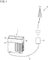
- FIG. 1 is a diagram of a communication system for an air conditioner according to an embodiment.
- the following description mainly concerns a configuration and functions of a communication system for an air conditioner.
- the structure and functions inherent in an air conditioner for air conditioning will not be described here.
- FIG. 1 illustrates constituent elements of the communication system depicted for making the presence of each element evident; therefore, the dimensions of each component are different from actual ones.
- an air conditioner i.e., an outdoor unit
- the air conditioner 1 also includes a control board 12 and a communication conversion unit 13 disposed beside the control board 12.
- the housing 11 accommodates therein the control board 12 and the communication conversion unit 13.
- a cable 2 is connected at its first end to the communication conversion unit 13.
- the cable 2 is drawn out of the housing 11 from, for example, a lower side of the housing 11 to outside.
- the cable 2 is, for example, a two-wire vinyl cabtyre cable (VCT).
- a two-wire vinyl cabtyre cable is available with ease and requires, at its end, no dedicated connector such as an F-type plug of a coaxial cable.
- the two-wire vinyl cabtyre cable is therefore inexpensive as a whole.
- the two-wire vinyl cabtyre cable is also excellent in weather resistance, and is therefore suitable for outdoor use.
- the cable 2 is also connected at its second end (an upper right end in FIG. 1 ) to an antenna unit 3.
- the cable 2 is not an accessory of the air conditioner 1 or the antenna unit 3, but is a product to be procured at the site of installation. Therefore, the length of the cable 2 is not fixed.
- the antenna unit 3 is installed near the air conditioner 1 at a place suitable for communication with a base station 4.
- the cable 2 of appropriate length is prepared for connecting the communication conversion unit 13 to the antenna unit 3.
- the cable 2 may have a length up to, for example, about 30 m. As long as communication is favorably established with good sensitivity even at the place where the air conditioner 1 is installed, the antenna unit 3 may be mounted to an outer surface of the housing 11 of the air conditioner 1.
- the antenna unit 3 is, for example, a communication device for Sigfox, and is capable of wireless communication with the base station 4 in the sub-GHz band (920 MHz in Japan, 868 MHz in Europe, 915 MHz in North America).
- the communication speed is, for example, about 100 bps.
- the base station 4 is a base station for Sigfox.
- a maximum value of a distance from the antenna unit 3 to the base station 4, that is, a maximum propagation distance is, for example, about 50 km.
- FIG. 2 is an electrical block diagram of the communication system illustrated in FIG. 1 , which also illustrates a connection over the Internet.
- the control board 12 is connected to the communication conversion unit 13 in the housing 11 of the air conditioner (i.e., the outdoor unit) 1.
- the communication conversion unit 13 is disposed in proximity to the control board 12 such that an electric circuit 14 between the communication conversion unit 13 and the control board 12 is as short as possible. Reducing the distance between the communication conversion unit 13 and the control board 12 enables suppression of surge noise.
- a control power voltage (Vcc) is gained from the control board 12 using a short connecting wire.
- the communication conversion unit 13 acquires various kinds of information from the control board 12 in the form of electric signals.
- the communication conversion unit 13 converts the electric signals into encoded digital signals by, for example, alternate mark inversion (AMI).
- AMI is a method of transmitting a digital signal by half-duplex communication. According to AMI, a signal is transmitted by applying a signal voltage excluding a direct current component and taking zero, a positive value or a negative value across the two wires of the cable 2 serving as a transmission line.
- a control power voltage (Vcc: e.g., DC 16 V) for the air conditioner 1 is applied as a reference voltage across the two wires of the cable 2.
- the signal transmission is made in such a manner that a signal voltage corresponding to a code of a signal for AMI is superimposed on the control power voltage.
- the communication using the cable 2 is established by AMI which is an encoded digital communication method less susceptible to an influence of surge noise. This configuration therefore suppresses an influence of surge noise.
- the cable 2 is an antenna line configured to carry a digital signal for wire transmission rather than a signal for wireless transmission, and is therefore less susceptible to an influence of surge noise.
- the cable 2 is also capable of feeding a power voltage to the antenna unit 3. This configuration therefore eliminates a necessity of a power supply dedicated to the antenna unit 3.
- the communication conversion unit 33 of the antenna unit 3 is configured to convert a signal for AMI into a signal for Sigfox.
- the signal for Sigfox thus obtained by conversion is radiated at a radio frequency of, for example, 920 MHz from a communication unit 34 and an antenna 35 of the communication unit 34.
- the communication conversion unit 33 generates a communication signal for Sigfox, in the immediate vicinity of the antenna 35. This configuration therefore suppresses an influence of surge noise more effectively.
- the base station 4 receives the radio waves from the antenna unit 3.
- the LPWA communication method such as Sigfox enables the antenna unit 3 to communicate with the base station 4 with low power consumption and at low cost.
- the base station 4 Upon reception of the radio waves, the base station 4 sends the information on the air conditioner 1 to the server 6 over the Internet 5.
- the base station 4 receives radio waves from a plurality of (a number of) air conditioners 1, and sends information on each air conditioner to the server 6. This system achieves remote control of multiple air conditioners, using the server 6.
- FIG. 2 illustrates signal transmission from the air conditioner 1 to the server 6. However, if the communication system is designed to achieve bidirectional signal transmission, then the communication system achieves downstream communication from the server 6 to air conditioner 1 with ease.
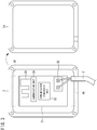
- FIG. 3 is a diagram of an exemplary actual configuration of the antenna unit 3.
- the antenna unit 3 includes a main body (the left side in FIG. 3 ) and a cover 3a (the right side in FIG. 3).
- FIG. 3 illustrates the antenna unit 3 from which the cover 3a is removed.
- the main body (the left side in FIG. 3 ) includes a substrate 31 as well as terminal blocks 32, the communication conversion unit 33, a communication unit 34, and an antenna 35 each mounted on the substrate 31.
- the two wires of the cable 2 are respectively connected to the terminal blocks 32.
- a coaxial cable requires at its end a dedicated connector such as an F-type plug.
- the vinyl cabtyre cable requires no dedicated connector, and therefore enables a simple connection as illustrated in FIG. 3 .
- the cover 3a is placed on the main body, and is fastened to the main body with screws and waterproof O-rings (not illustrated) at the four corners.
- the antenna unit 3 is thus resistant to water and is suitable for outdoor use.
- the antenna unit 3 may be fixed with, for example, screws.
- the antenna unit 3 may have, on its back side, magnets 36. With this configuration, the antenna unit 3 is easily attached to the housing 11, which is made of a metal such as iron, of the air conditioner 1 and other portions made of iron, without thread cutting.
- the present disclosure provides a communication system for an air conditioner 1 including a housing 11 and a control board 12 accommodated in the housing 11.
- the communication system includes a communication conversion unit 13 accommodated in the housing 11 and configured to acquire a required electric signal from the control board 12 and to convert the electric signal into a digital signal for wire transmission.
- the communication system also includes a cable 2 having a first end connected to the communication conversion unit 13, the cable 2 being drawn out of the housing 11 to outside.
- the communication system also includes an antenna unit 3 connected to a second end of the cable 2 located outside the housing 11, the antenna unit 3 being configured to establish wireless communication with a base station 4.
- the present disclosure also provides an air conditioner 1 including: a housing 11; a control board 12 accommodated in the housing 11; a communication conversion unit 13 accommodated in the housing 11 and configured to acquire a required electric signal from the control board 12 and to convert the electric signal into a digital signal for wire transmission; a cable 2 having a first end connected to the communication conversion unit 13, the cable 2 being drawn out of the housing 11 to outside; and an antenna unit 3 connected to a second end of the cable 2 located outside the housing 11, the antenna unit 3 being configured to establish wireless communication with a base station 4.
- the position of the antenna unit 3 is not limited to the interior of the housing 11 of the air conditioner 1.
- the antenna unit 3 is freely installed at a desired position suitable for communication, using the cable 2.
- the cable 2 is an antenna line configured to carry a digital signal for wire transmission rather than a signal for wireless transmission, and is therefore less susceptible to an influence of surge noise.
- the antenna unit 3 is installed at a higher degree of freedom. The communication system is therefore easy to install, and establishes communication without any trouble. This configuration accordingly allows the antenna unit 3 to be retrofitted to an existing air conditioner with ease.
- a LPWA communication method e.g., Sigfox
- a digital communication method e.g., AMI
- Adopting the LPWA communication method such as Sigfox enables long-range communication between the antenna unit and the base station with reduced power consumption and at reduced cost.
- the communication using the cable is established by AMI which is an encoded digital communication method less susceptible to an influence of surge noise. This configuration therefore suppresses an influence of surge noise.
- the communication conversion unit 13 is disposed in proximity to the control board 12 in the housing 11.
- the antenna unit 3 includes a communication conversion unit 33 configured to convert the digital signal into a communication signal for the LPWA communication method.
- the communication conversion unit 33 generates the communication signal for the LPWA communication method, in the immediate vicinity of an antenna 35. This configuration therefore suppresses an influence of surge noise more effectively.
- the digital signal is a signal superimposed on a power voltage for the antenna unit 3.
- This configuration eliminates a necessity of a power supply dedicated to the antenna unit 3.
- the cable 2 is a two-wire vinyl cabtyre cable.
- a two-wire vinyl cabtyre cable is available with ease, and requires no dedicated connector at its end.
- the two-wire vinyl cabtyre cable is inexpensive as a whole, and is excellent in weather resistance.
- the antenna unit 3 includes a magnet 36 for magnetic adsorption.
- the antenna unit 3 is fixable to any position of an iron plate with ease at a place where the antenna unit 3 is capable of wireless communication with the base station 4.
- the antenna unit 3 may be fixed to an outer surface of the housing 11 of the air conditioner 1 (i.e., the outdoor unit).
- This configuration therefore requires no construction such as boring, and also requires no waterproof treatment associated with boring. This configuration thus enables rapid installation of the communication system.
- the disclosure describes the LPWA communication method. However, the communication method is not limited to the LPWA communication method. Other communication methods may be applicable now or in the future.
- the disclosure also describes Sigfox as a specific example of the LPWA communication method. However, a specific example of the LPWA communication method is not limited to Sigfox. Specific examples of the LPWA communication method may include, but not limited to, LoRa (registered trademark) and NB-IoT.
- the communication using the cable 2 is not limited to AMI.
- the disclosure does not intend to exclude other digital communication methods.
Landscapes
- Engineering & Computer Science (AREA)
- Computer Networks & Wireless Communication (AREA)
- Signal Processing (AREA)
- Health & Medical Sciences (AREA)
- Computing Systems (AREA)
- General Health & Medical Sciences (AREA)
- Medical Informatics (AREA)
- Physics & Mathematics (AREA)
- General Physics & Mathematics (AREA)
- Air Conditioning Control Device (AREA)
- Selective Calling Equipment (AREA)
- Computer Security & Cryptography (AREA)
Abstract
Description
- The present disclosure relates to communications mainly for an air conditioner for industrial use.
- There are various air conditioners such as simple air conditioners for home use and large air conditioners for industrial use. An air conditioner manufacturer offers service of surveillance and maintenance of particularly air conditioners for industrial use. For example, there has been proposed a technique of reading information in a contactless manner by bringing an information terminal close to a transceiver in an outdoor unit of an air conditioner, the transceiver being configured to provide information on the outdoor unit for, for example, maintenance inspection or repair of the air conditioner (refer to, for example, Patent Literature 1).
- With a recent quantum leap in Internet-related technology, the Internet of Things (IoT) that enables remote control and operation on an apparatus of interest over the Internet has been taken into consideration in the various fields including air conditioners. For example, an outdoor unit of an air conditioner includes a communication unit configured to establish wireless communication with a base station. An air conditioner manufacturer is thus able to collect information on the air conditioner, using a server connected to the base station over the Internet, and is also able to operate the air conditioner at a remote site.
- Patent Literature 1:
WO 2016/080352 A1 - In a typical air conditioner, a housing of an outdoor unit is made of a metal such as iron. The metal housing hinders radio waves from reaching a communication unit disposed in the outdoor unit.
- In view of the circumstance described above, the present disclosure provides a communication system for an air conditioner, the communication system being easy to install and establishing communication without any trouble, and an air conditioner in the communication system.
-
- (1) The present disclosure provides a communication system for an air conditioner including a housing and a control board accommodated in the housing. The communication system includes a communication conversion unit accommodated in the housing and configured to acquire a required electric signal from the control board and to convert the electric signal into a digital signal for wire transmission. The communication system also includes a cable having a first end connected to the communication conversion unit, the cable being drawn out of the housing to outside. The communication system also includes an antenna unit connected to a second end of the cable located outside the housing, the antenna unit being configured to establish wireless communication with a base station.
With this configuration, the communication system is easy to install, and establishes communication without any trouble. - (2) In the communication system as recited in (1), for example, communication between the antenna unit and the base station is established by a low power wide area (LPWA) communication method, and communication using the cable is established by a digital communication different from the LPWA communication method.
According to the LPWA communication method, a volume of data to be transmitted at a time is small. However, data is transmittable with lower power consumption and at lower cost. In addition, the LPWA communication method achieves a far longer communication range than Wi-Fi (WiFi is a registered trademark) and Bluetooth (registered trademark). Adopting the LPWA communication method such as Sigfox (SIGFOX is a registered trademark) enables long-range communication between the antenna unit and the base station with reduced power consumption and at reduced cost. The communication using the cable is established by, for example, alternate mark inversion (AMI) which is an encoded digital communication method less susceptible to an influence of surge noise. This configuration therefore suppresses an influence of surge noise. - (3) In the communication system as recited in (1) or (2), preferably, the communication conversion unit is disposed in proximity to the control board in the housing.
With this configuration, reducing the distance between the communication conversion unit and the control board enables suppression of surge noise. In addition, a control power voltage is gained from the control board using a shorter connecting wire. - (4) In the communication system as recited in (2), for example, the antenna unit includes a communication conversion unit configured to convert the digital signal into a communication signal for the LPWA communication method.
With this configuration, the communication conversion unit generates the communication signal for the LPWA communication method, in the immediate vicinity of an antenna. This configuration therefore suppresses an influence of surge noise more effectively. - (5) In the communication system as recited in any of (1) to (4), the digital signal may be a signal superimposed on a power voltage for the antenna unit.
This configuration eliminates a necessity of a power supply dedicated to the antenna unit. - (6) In the communication system as recited in any of (1) to (5), the cable may be a two-wire vinyl cabtyre cable.
A two-wire vinyl cabtyre cable is available with ease, and requires no dedicated connector at its end. In addition, the two-wire vinyl cabtyre cable is inexpensive as a whole, and is excellent in weather resistance. - (7) In the communication system as recited in any of (1) to (6), the antenna unit may include a magnet for magnetic adsorption.
With this configuration, the antenna unit is fixable to any position of an iron plate with ease at a place where the antenna unit is capable of wireless communication with the base station. For example, the antenna unit may be fixed to an outer surface of the housing of the air conditioner (i.e., the outdoor unit). This configuration therefore requires no construction such as boring, and also requires no waterproof treatment associated with boring. This configuration thus enables rapid installation of the communication system. - (8) The present disclosure also provides an air conditioner including: a housing; a control board accommodated in the housing; a communication conversion unit accommodated in the housing and configured to acquire a required electric signal from the control board and to convert the electric signal into a digital signal for wire transmission; a cable having a first end connected to the communication conversion unit, the cable being drawn out of the housing to outside; and an antenna unit connected to a second end of the cable located outside the housing, the antenna unit being configured to establish wireless communication with a base station.
- With this configuration, the air conditioner including the communication conversion unit and the antenna unit is easy to install, and establishes communication without any trouble.
-
-
FIG. 1 is a diagram of a communication system for an air conditioner according to an embodiment. -
FIG. 2 is an electrical block diagram of the communication system illustrated inFIG. 1 , which also illustrates a connection over the Internet. -
FIG. 3 is a diagram of an exemplary actual configuration of anantenna unit 3. -
FIG. 1 is a diagram of a communication system for an air conditioner according to an embodiment. The following description mainly concerns a configuration and functions of a communication system for an air conditioner. The structure and functions inherent in an air conditioner for air conditioning will not be described here. -
FIG. 1 illustrates constituent elements of the communication system depicted for making the presence of each element evident; therefore, the dimensions of each component are different from actual ones. - As illustrated in
FIG. 1 , an air conditioner (i.e., an outdoor unit) 1 includes ahousing 11 made of a metal such as iron. Theair conditioner 1 also includes acontrol board 12 and acommunication conversion unit 13 disposed beside thecontrol board 12. Thehousing 11 accommodates therein thecontrol board 12 and thecommunication conversion unit 13. Acable 2 is connected at its first end to thecommunication conversion unit 13. Thecable 2 is drawn out of thehousing 11 from, for example, a lower side of thehousing 11 to outside. Thecable 2 is, for example, a two-wire vinyl cabtyre cable (VCT). - A two-wire vinyl cabtyre cable is available with ease and requires, at its end, no dedicated connector such as an F-type plug of a coaxial cable. The two-wire vinyl cabtyre cable is therefore inexpensive as a whole. The two-wire vinyl cabtyre cable is also excellent in weather resistance, and is therefore suitable for outdoor use. The
cable 2 is also connected at its second end (an upper right end inFIG. 1 ) to anantenna unit 3. - The
cable 2 is not an accessory of theair conditioner 1 or theantenna unit 3, but is a product to be procured at the site of installation. Therefore, the length of thecable 2 is not fixed. Theantenna unit 3 is installed near theair conditioner 1 at a place suitable for communication with abase station 4. In addition, thecable 2 of appropriate length is prepared for connecting thecommunication conversion unit 13 to theantenna unit 3. Thecable 2 may have a length up to, for example, about 30 m. As long as communication is favorably established with good sensitivity even at the place where theair conditioner 1 is installed, theantenna unit 3 may be mounted to an outer surface of thehousing 11 of theair conditioner 1. - The
antenna unit 3 is, for example, a communication device for Sigfox, and is capable of wireless communication with thebase station 4 in the sub-GHz band (920 MHz in Japan, 868 MHz in Europe, 915 MHz in North America). The communication speed is, for example, about 100 bps. Thebase station 4 is a base station for Sigfox. A maximum value of a distance from theantenna unit 3 to thebase station 4, that is, a maximum propagation distance is, for example, about 50 km. -
FIG. 2 is an electrical block diagram of the communication system illustrated inFIG. 1 , which also illustrates a connection over the Internet. As illustrated inFIG. 2 , thecontrol board 12 is connected to thecommunication conversion unit 13 in thehousing 11 of the air conditioner (i.e., the outdoor unit) 1. Thecommunication conversion unit 13 is disposed in proximity to thecontrol board 12 such that anelectric circuit 14 between thecommunication conversion unit 13 and thecontrol board 12 is as short as possible. Reducing the distance between thecommunication conversion unit 13 and thecontrol board 12 enables suppression of surge noise. In addition, a control power voltage (Vcc) is gained from thecontrol board 12 using a short connecting wire. - The
communication conversion unit 13 acquires various kinds of information from thecontrol board 12 in the form of electric signals. Thecommunication conversion unit 13 converts the electric signals into encoded digital signals by, for example, alternate mark inversion (AMI). AMI is a method of transmitting a digital signal by half-duplex communication. According to AMI, a signal is transmitted by applying a signal voltage excluding a direct current component and taking zero, a positive value or a negative value across the two wires of thecable 2 serving as a transmission line. A control power voltage (Vcc: e.g., DC 16 V) for theair conditioner 1 is applied as a reference voltage across the two wires of thecable 2. The signal transmission is made in such a manner that a signal voltage corresponding to a code of a signal for AMI is superimposed on the control power voltage. - The communication using the
cable 2 is established by AMI which is an encoded digital communication method less susceptible to an influence of surge noise. This configuration therefore suppresses an influence of surge noise. Thecable 2 is an antenna line configured to carry a digital signal for wire transmission rather than a signal for wireless transmission, and is therefore less susceptible to an influence of surge noise. - The
cable 2 is also capable of feeding a power voltage to theantenna unit 3. This configuration therefore eliminates a necessity of a power supply dedicated to theantenna unit 3. - The
communication conversion unit 33 of theantenna unit 3 is configured to convert a signal for AMI into a signal for Sigfox. The signal for Sigfox thus obtained by conversion is radiated at a radio frequency of, for example, 920 MHz from acommunication unit 34 and anantenna 35 of thecommunication unit 34. In theantenna unit 3, thecommunication conversion unit 33 generates a communication signal for Sigfox, in the immediate vicinity of theantenna 35. This configuration therefore suppresses an influence of surge noise more effectively. - The
base station 4 receives the radio waves from theantenna unit 3. The LPWA communication method such as Sigfox enables theantenna unit 3 to communicate with thebase station 4 with low power consumption and at low cost. - Upon reception of the radio waves, the
base station 4 sends the information on theair conditioner 1 to theserver 6 over theInternet 5. In practice, thebase station 4 receives radio waves from a plurality of (a number of)air conditioners 1, and sends information on each air conditioner to theserver 6. This system achieves remote control of multiple air conditioners, using theserver 6. - Since only the upstream communication is currently authorized as to Sigfox,
FIG. 2 illustrates signal transmission from theair conditioner 1 to theserver 6. However, if the communication system is designed to achieve bidirectional signal transmission, then the communication system achieves downstream communication from theserver 6 toair conditioner 1 with ease. -
FIG. 3 is a diagram of an exemplary actual configuration of theantenna unit 3. As illustrated inFIG. 3 , theantenna unit 3 includes a main body (the left side inFIG. 3 ) and acover 3a (the right side inFIG. 3). FIG. 3 illustrates theantenna unit 3 from which thecover 3a is removed. The main body (the left side inFIG. 3 ) includes asubstrate 31 as well as terminal blocks 32, thecommunication conversion unit 33, acommunication unit 34, and anantenna 35 each mounted on thesubstrate 31. The two wires of thecable 2 are respectively connected to the terminal blocks 32. A coaxial cable requires at its end a dedicated connector such as an F-type plug. However, the vinyl cabtyre cable requires no dedicated connector, and therefore enables a simple connection as illustrated inFIG. 3 . - The
cover 3a is placed on the main body, and is fastened to the main body with screws and waterproof O-rings (not illustrated) at the four corners. Theantenna unit 3 is thus resistant to water and is suitable for outdoor use. Theantenna unit 3 may be fixed with, for example, screws. Alternatively, theantenna unit 3 may have, on its back side,magnets 36. With this configuration, theantenna unit 3 is easily attached to thehousing 11, which is made of a metal such as iron, of theair conditioner 1 and other portions made of iron, without thread cutting. - For example, the disclosure may be summarized and represented as follows. However, the following representations are merely illustrative and not restrictive.
- The present disclosure provides a communication system for an
air conditioner 1 including ahousing 11 and acontrol board 12 accommodated in thehousing 11. The communication system includes acommunication conversion unit 13 accommodated in thehousing 11 and configured to acquire a required electric signal from thecontrol board 12 and to convert the electric signal into a digital signal for wire transmission. The communication system also includes acable 2 having a first end connected to thecommunication conversion unit 13, thecable 2 being drawn out of thehousing 11 to outside. The communication system also includes anantenna unit 3 connected to a second end of thecable 2 located outside thehousing 11, theantenna unit 3 being configured to establish wireless communication with abase station 4. - The present disclosure also provides an
air conditioner 1 including: ahousing 11; acontrol board 12 accommodated in thehousing 11; acommunication conversion unit 13 accommodated in thehousing 11 and configured to acquire a required electric signal from thecontrol board 12 and to convert the electric signal into a digital signal for wire transmission; acable 2 having a first end connected to thecommunication conversion unit 13, thecable 2 being drawn out of thehousing 11 to outside; and anantenna unit 3 connected to a second end of thecable 2 located outside thehousing 11, theantenna unit 3 being configured to establish wireless communication with abase station 4. - In the communication system for the air conditioner and the air conditioner, the position of the
antenna unit 3 is not limited to the interior of thehousing 11 of theair conditioner 1. With this configuration, theantenna unit 3 is freely installed at a desired position suitable for communication, using thecable 2. This configuration thus causes no communication trouble even when the housing is made of a metal. Thecable 2 is an antenna line configured to carry a digital signal for wire transmission rather than a signal for wireless transmission, and is therefore less susceptible to an influence of surge noise. In the communication system, theantenna unit 3 is installed at a higher degree of freedom. The communication system is therefore easy to install, and establishes communication without any trouble. This configuration accordingly allows theantenna unit 3 to be retrofitted to an existing air conditioner with ease. - For example, communication between the
antenna unit 3 and thebase station 4 is established by a LPWA communication method (e.g., Sigfox), and communication using thecable 2 is established by a digital communication method (e.g., AMI) different from the LPWA communication method. - Adopting the LPWA communication method such as Sigfox enables long-range communication between the antenna unit and the base station with reduced power consumption and at reduced cost. The communication using the cable is established by AMI which is an encoded digital communication method less susceptible to an influence of surge noise. This configuration therefore suppresses an influence of surge noise.
- Preferably, the
communication conversion unit 13 is disposed in proximity to thecontrol board 12 in thehousing 11. - With this configuration, reducing the distance between the
communication conversion unit 13 and thecontrol board 12 enables suppression of surge noise. In addition, a control power voltage is gained from thecontrol board 12 using a shorter connecting wire. - For example, the
antenna unit 3 includes acommunication conversion unit 33 configured to convert the digital signal into a communication signal for the LPWA communication method. - With this configuration, the
communication conversion unit 33 generates the communication signal for the LPWA communication method, in the immediate vicinity of anantenna 35. This configuration therefore suppresses an influence of surge noise more effectively. - For example, the digital signal is a signal superimposed on a power voltage for the
antenna unit 3. - This configuration eliminates a necessity of a power supply dedicated to the
antenna unit 3. - For example, the
cable 2 is a two-wire vinyl cabtyre cable. - A two-wire vinyl cabtyre cable is available with ease, and requires no dedicated connector at its end. In addition, the two-wire vinyl cabtyre cable is inexpensive as a whole, and is excellent in weather resistance.
- For example, the
antenna unit 3 includes amagnet 36 for magnetic adsorption. - With this configuration, the
antenna unit 3 is fixable to any position of an iron plate with ease at a place where theantenna unit 3 is capable of wireless communication with thebase station 4. For example, theantenna unit 3 may be fixed to an outer surface of thehousing 11 of the air conditioner 1 (i.e., the outdoor unit). This configuration therefore requires no construction such as boring, and also requires no waterproof treatment associated with boring. This configuration thus enables rapid installation of the communication system. - The disclosure describes the LPWA communication method. However, the communication method is not limited to the LPWA communication method. Other communication methods may be applicable now or in the future. The disclosure also describes Sigfox as a specific example of the LPWA communication method. However, a specific example of the LPWA communication method is not limited to Sigfox. Specific examples of the LPWA communication method may include, but not limited to, LoRa (registered trademark) and NB-IoT.
- In addition, the communication using the
cable 2 is not limited to AMI. The disclosure does not intend to exclude other digital communication methods. - While various embodiments have been described herein above, it is to be appreciated that various changes in form and detail may be made without departing from the spirit and scope presently or hereafter claimed.
-
- 1: AIR CONDITIONER (OUTDOOR UNIT)
- 2: CABLE
- 3: ANTENNA UNIT
- 3a: COVER
- 4: BASE STATION
- 5: INTERNET
- 6: SERVER
- 11: HOUSING
- 12: CONTROL BOARD
- 13: COMMUNICATION CONVERSION UNIT
- 14: ELECTRIC CIRCUIT
- 31: SUBSTRATE
- 32: TERMINAL BLOCK
- 33: COMMUNICATION CONVERSION UNIT
- 34: COMMUNICATION UNIT
- 35: ANTENNA
- 36: MAGNET
Claims (8)
- A communication system for an air conditioner (1) including a housing (11) and a control board (12) accommodated in the housing (11),
the communication system comprising:a communication conversion unit (13) accommodated in the housing (11) and configured to acquire a required electric signal from the control board (12) and to convert the electric signal into a digital signal for wire transmission;a cable (2) having a first end connected to the communication conversion unit (13), the cable (2) being drawn out of the housing (11) to outside; andan antenna unit (3) connected to a second end of the cable (2) located outside the housing (11), the antenna unit (3) being configured to establish wireless communication with a base station (4). - The communication system according to claim 1, wherein
communication between the antenna unit (3) and the base station (4) is established by a low power wide area (LPWA) communication method, and
communication using the cable (2) is established by a digital communication method different from the LPWA communication method. - The communication system according to claim 1 or 2, wherein
the communication conversion unit (13) is disposed in proximity to the control board (12) in the housing (11). - The communication system according to claim 2, wherein
the antenna unit (3) includes a communication conversion unit (33) configured to convert the digital signal into a communication signal for the LPWA communication method. - The communication system according to any one of claims 1 to 4, wherein
the digital signal is a signal superimposed on a power voltage for the antenna unit (3). - The communication system according to any one of claims 1 to 5, wherein
the cable (2) is a two-wire vinyl cabtyre cable. - The communication system according to any one of claims 1 to 6, wherein
the antenna unit (3) includes a magnet (36) for magnetic adsorption. - An air conditioner (1) comprising:a housing (11);a control board (12) accommodated in the housing (11);a communication conversion unit (13) accommodated in the housing (11) and configured to acquire a required electric signal from the control board (12) and to convert the electric signal into a digital signal for wire transmission;a cable (2) having a first end connected to the communication conversion unit (13),the cable (2) being drawn out of the housing (11) to outside; andan antenna unit (3) connected to a second end of the cable (2) located outside the housing (11),the antenna unit (3) being configured to establish wireless communication with a base station (4).
Applications Claiming Priority (2)
| Application Number | Priority Date | Filing Date | Title |
|---|---|---|---|
| JP2018132034A JP6721008B2 (en) | 2018-07-12 | 2018-07-12 | Air conditioner communication system and air conditioner |
| PCT/JP2019/019286 WO2020012773A1 (en) | 2018-07-12 | 2019-05-15 | Air conditioner communication system and air conditioner |
Publications (2)
| Publication Number | Publication Date |
|---|---|
| EP3822549A1 true EP3822549A1 (en) | 2021-05-19 |
| EP3822549A4 EP3822549A4 (en) | 2021-08-25 |
Family
ID=69142847
Family Applications (1)
| Application Number | Title | Priority Date | Filing Date |
|---|---|---|---|
| EP19833292.6A Withdrawn EP3822549A4 (en) | 2018-07-12 | 2019-05-15 | AIR CONDITIONING COMMUNICATION SYSTEM AND AIR CONDITIONING |
Country Status (5)
| Country | Link |
|---|---|
| US (1) | US11425198B2 (en) |
| EP (1) | EP3822549A4 (en) |
| JP (1) | JP6721008B2 (en) |
| CN (1) | CN112219067A (en) |
| WO (1) | WO2020012773A1 (en) |
Families Citing this family (8)
| Publication number | Priority date | Publication date | Assignee | Title |
|---|---|---|---|---|
| WO2021240745A1 (en) | 2020-05-28 | 2021-12-02 | 三菱電機株式会社 | Air conditioning system, air conditioner, management server, authentication information providing method and program |
| JP2022110407A (en) * | 2021-01-18 | 2022-07-29 | 三菱電機株式会社 | Communication device for air conditioning and air conditioner |
| WO2022230044A1 (en) * | 2021-04-27 | 2022-11-03 | 三菱電機株式会社 | Outdoor unit and air-conditioning device |
| JP7181674B1 (en) | 2021-07-06 | 2022-12-01 | 株式会社 ミックウェア | Control system and control method |
| JP7729278B2 (en) * | 2022-07-22 | 2025-08-26 | 横河電機株式会社 | signal conversion device |
| JPWO2024236616A1 (en) * | 2023-05-12 | 2024-11-21 | ||
| WO2025191800A1 (en) * | 2024-03-14 | 2025-09-18 | 三菱電機株式会社 | Outdoor machine and management system |
| WO2025197008A1 (en) * | 2024-03-21 | 2025-09-25 | 三菱電機株式会社 | Wireless communication device |
Family Cites Families (36)
| Publication number | Priority date | Publication date | Assignee | Title |
|---|---|---|---|---|
| JPS4879300U (en) | 1971-12-29 | 1973-09-28 | ||
| JPS5472678U (en) * | 1977-11-02 | 1979-05-23 | ||
| JPH0731048A (en) | 1993-07-14 | 1995-01-31 | Miyaden:Kk | Connecting cable for high frequency heater |
| JPH10185649A (en) | 1996-12-25 | 1998-07-14 | Kimmon Mfg Co Ltd | Wireless meter inspecting device |
| JP2002013761A (en) * | 2000-06-28 | 2002-01-18 | Mitsubishi Heavy Ind Ltd | Air-conditioning system and its outdoor machine and indoor machine |
| US20050264474A1 (en) * | 2000-08-07 | 2005-12-01 | Rast Rodger H | System and method of driving an array of optical elements |
| JP2004028384A (en) | 2002-06-24 | 2004-01-29 | Hitachi Ltd | Air conditioner system |
| JP3903345B2 (en) | 2004-02-06 | 2007-04-11 | 株式会社日立製作所 | Central control device and air conditioner service system |
| JP2005277987A (en) | 2004-03-26 | 2005-10-06 | Kenwood Corp | Navigation device |
| KR20080079484A (en) * | 2007-02-27 | 2008-09-01 | 엘지전자 주식회사 | Air Conditioning System of Base Station and Its Operation Method |
| JP2010139158A (en) | 2008-12-11 | 2010-06-24 | Aisin Seiki Co Ltd | Outdoor unit for heat pump type air conditioner |
| US8596550B2 (en) * | 2009-05-12 | 2013-12-03 | Ecofactor, Inc. | System, method and apparatus for identifying manual inputs to and adaptive programming of a thermostat |
| JP2011180668A (en) * | 2010-02-26 | 2011-09-15 | Yokogawa Electric Corp | Field equipment control system |
| JP5708517B2 (en) | 2012-02-01 | 2015-04-30 | ダイキン工業株式会社 | Refrigeration unit outdoor unit |
| JP6081193B2 (en) | 2012-12-26 | 2017-02-15 | 株式会社東芝 | Memory device, maintenance work support program, memory system and maintenance system |
| DE112013007328B4 (en) | 2013-08-09 | 2020-06-18 | Therm-O-Disc, Incorporated | Wireless temperature and / or humidity sensor arrangement |
| JP6092766B2 (en) | 2013-12-26 | 2017-03-08 | ソフトバンク株式会社 | Air conditioning system |
| WO2015193976A1 (en) * | 2014-06-17 | 2015-12-23 | 三菱電機株式会社 | Air-conditioning system |
| JP6378997B2 (en) | 2014-09-30 | 2018-08-22 | 三菱重工サーマルシステムズ株式会社 | Outdoor unit |
| EP3222925B1 (en) | 2014-11-18 | 2020-09-30 | Toshiba Carrier Corporation | Outdoor unit |
| JP2016133294A (en) | 2015-01-22 | 2016-07-25 | ジョンソンコントロールズ ヒタチ エア コンディショニング テクノロジー(ホンコン)リミテッド | Air-conditioner maintenance and maintenance system and method |
| CN204693661U (en) * | 2015-05-07 | 2015-10-07 | 珠海格力电器股份有限公司 | Air condensing units and air conditioning unit |
| JP2016220151A (en) | 2015-05-25 | 2016-12-22 | パナソニックIpマネジメント株式会社 | Transmission unit and communication system using the same |
| JP6417476B2 (en) * | 2015-06-25 | 2018-11-07 | 東芝キヤリア株式会社 | Outdoor unit |
| US9948349B2 (en) * | 2015-07-17 | 2018-04-17 | Corning Optical Communications Wireless Ltd | IOT automation and data collection system |
| US10734314B2 (en) | 2015-08-31 | 2020-08-04 | Aisin Aw Co., Ltd. | Semiconductor device and semiconductor module |
| CN205245392U (en) * | 2015-10-30 | 2016-05-18 | 大金工业株式会社 | Air conditioner outdoor unit |
| CN205452520U (en) | 2015-12-16 | 2016-08-10 | 珠海格力电器股份有限公司 | Air conditioner |
| ES2790425T3 (en) | 2016-02-26 | 2020-10-27 | Daikin Ind Ltd | Remote management system |
| JP2017192021A (en) | 2016-04-13 | 2017-10-19 | 日本電信電話株式会社 | Radio communication system and radio communication method |
| JP6364571B1 (en) | 2016-09-26 | 2018-07-25 | 株式会社ミツウロコクリエイティブソリューションズ | Gas supply management system, gas supply management method, information transmission device |
| EP3521722B1 (en) | 2016-09-30 | 2023-11-29 | Daikin Industries, Ltd. | Air conditioner management system, communication condition adjustment method |
| US10094588B2 (en) | 2016-10-12 | 2018-10-09 | Invicon Inc. | Wifi vertical fan coil system |
| JP6930685B2 (en) | 2016-12-27 | 2021-09-01 | イー インク コーポレイション | Display device circuit boards, display devices and electronic devices |
| JP6852515B2 (en) * | 2017-03-31 | 2021-03-31 | 沖電気工業株式会社 | Sensor management system, sensor management method, sensor management program and sensor management device |
| CN207338278U (en) * | 2017-06-21 | 2018-05-08 | 国家电网公司 | A kind of breaker remote control device |
-
2018
- 2018-07-12 JP JP2018132034A patent/JP6721008B2/en active Active
-
2019
- 2019-05-15 CN CN201980037019.4A patent/CN112219067A/en active Pending
- 2019-05-15 EP EP19833292.6A patent/EP3822549A4/en not_active Withdrawn
- 2019-05-15 US US17/051,050 patent/US11425198B2/en active Active
- 2019-05-15 WO PCT/JP2019/019286 patent/WO2020012773A1/en not_active Ceased
Also Published As
| Publication number | Publication date |
|---|---|
| WO2020012773A1 (en) | 2020-01-16 |
| JP6721008B2 (en) | 2020-07-08 |
| JP2020008261A (en) | 2020-01-16 |
| US11425198B2 (en) | 2022-08-23 |
| EP3822549A4 (en) | 2021-08-25 |
| CN112219067A (en) | 2021-01-12 |
| US20210092189A1 (en) | 2021-03-25 |
Similar Documents
| Publication | Publication Date | Title |
|---|---|---|
| US11425198B2 (en) | Communication system for air conditioner, and air conditioner | |
| US20150102941A1 (en) | Metering device and parts therefor | |
| EP1241058A2 (en) | Rotary non-contact connector and non-rotary non-contact connector | |
| JP2017034935A (en) | Wireless power transmission device | |
| US10910865B2 (en) | Power transmission communication unit | |
| EP3207591B1 (en) | A supply cable, a driver arrangement with wireless control function and a control method | |
| CN111615472A (en) | Distance receiver system for long-range LTE modules | |
| EP3261172A1 (en) | Pcb antenna | |
| US9421831B2 (en) | Magnetic force transmission type tire pressure sensor device and related setting tool and setting method | |
| JPWO2022230044A5 (en) | ||
| EP4135158B1 (en) | System for cellular and satellite broadband services | |
| CN103684536A (en) | Wireless communication apparatus | |
| US20140240194A1 (en) | Small-cell antenna arrangement | |
| JPH0946110A (en) | Diversity antenna device and communication device | |
| EP2813379A1 (en) | Magnetic force transmission type tire pressure sensor device and related setting tool and setting method | |
| KR101572251B1 (en) | Submarine | |
| CN207664969U (en) | A kind of unmanned aerial vehicle onboard receiver | |
| CN207010691U (en) | For detecting the device of interference electric signal | |
| GB2435765A (en) | TMC antenna | |
| CN108390700B (en) | Coupling device for feeding detection signal into high-voltage carrier wave | |
| CN110546521A (en) | wireless monitoring and configuration tether for use with isolated industrial products and method of operating same | |
| Baszynski et al. | Wireless energy transfer for industrial applications: Theory, available solutions and perspectives | |
| CN110366743B (en) | Remote control assistance device, remote controller, and remote control system | |
| CN107026699A (en) | device for detecting interference electric signal | |
| RU2263933C1 (en) | Pipeline insulation condition remote control system |
Legal Events
| Date | Code | Title | Description |
|---|---|---|---|
| STAA | Information on the status of an ep patent application or granted ep patent |
Free format text: STATUS: THE INTERNATIONAL PUBLICATION HAS BEEN MADE |
|
| TPAC | Observations filed by third parties |
Free format text: ORIGINAL CODE: EPIDOSNTIPA |
|
| PUAI | Public reference made under article 153(3) epc to a published international application that has entered the european phase |
Free format text: ORIGINAL CODE: 0009012 |
|
| STAA | Information on the status of an ep patent application or granted ep patent |
Free format text: STATUS: REQUEST FOR EXAMINATION WAS MADE |
|
| 17P | Request for examination filed |
Effective date: 20201110 |
|
| AK | Designated contracting states |
Kind code of ref document: A1 Designated state(s): AL AT BE BG CH CY CZ DE DK EE ES FI FR GB GR HR HU IE IS IT LI LT LU LV MC MK MT NL NO PL PT RO RS SE SI SK SM TR |
|
| REG | Reference to a national code |
Ref country code: DE Ref legal event code: R079 Free format text: PREVIOUS MAIN CLASS: F24F0001220000 Ipc: H04B0001380000 |
|
| A4 | Supplementary search report drawn up and despatched |
Effective date: 20210728 |
|
| RIC1 | Information provided on ipc code assigned before grant |
Ipc: H04B 1/38 20150101AFI20210722BHEP Ipc: F24F 1/22 20110101ALI20210722BHEP Ipc: F24F 11/58 20180101ALI20210722BHEP Ipc: H04Q 9/00 20060101ALI20210722BHEP |
|
| DAV | Request for validation of the european patent (deleted) | ||
| DAX | Request for extension of the european patent (deleted) | ||
| STAA | Information on the status of an ep patent application or granted ep patent |
Free format text: STATUS: EXAMINATION IS IN PROGRESS |
|
| 17Q | First examination report despatched |
Effective date: 20211210 |
|
| RAP3 | Party data changed (applicant data changed or rights of an application transferred) |
Owner name: DAIKIN INDUSTRIES, LTD. |
|
| GRAP | Despatch of communication of intention to grant a patent |
Free format text: ORIGINAL CODE: EPIDOSNIGR1 |
|
| STAA | Information on the status of an ep patent application or granted ep patent |
Free format text: STATUS: GRANT OF PATENT IS INTENDED |
|
| P01 | Opt-out of the competence of the unified patent court (upc) registered |
Effective date: 20230525 |
|
| INTG | Intention to grant announced |
Effective date: 20230623 |
|
| STAA | Information on the status of an ep patent application or granted ep patent |
Free format text: STATUS: THE APPLICATION IS DEEMED TO BE WITHDRAWN |
|
| 18D | Application deemed to be withdrawn |
Effective date: 20231104 |