EP3822481A1 - Fluid pump - Google Patents
Fluid pump Download PDFInfo
- Publication number
- EP3822481A1 EP3822481A1 EP20206094.3A EP20206094A EP3822481A1 EP 3822481 A1 EP3822481 A1 EP 3822481A1 EP 20206094 A EP20206094 A EP 20206094A EP 3822481 A1 EP3822481 A1 EP 3822481A1
- Authority
- EP
- European Patent Office
- Prior art keywords
- housing part
- sealing
- fluid pump
- sealing element
- sealing portion
- Prior art date
- Legal status (The legal status is an assumption and is not a legal conclusion. Google has not performed a legal analysis and makes no representation as to the accuracy of the status listed.)
- Granted
Links
Images

Classifications
-
- F—MECHANICAL ENGINEERING; LIGHTING; HEATING; WEAPONS; BLASTING
- F04—POSITIVE - DISPLACEMENT MACHINES FOR LIQUIDS; PUMPS FOR LIQUIDS OR ELASTIC FLUIDS
- F04C—ROTARY-PISTON, OR OSCILLATING-PISTON, POSITIVE-DISPLACEMENT MACHINES FOR LIQUIDS; ROTARY-PISTON, OR OSCILLATING-PISTON, POSITIVE-DISPLACEMENT PUMPS
- F04C15/00—Component parts, details or accessories of machines, pumps or pumping installations, not provided for in groups F04C2/00 - F04C14/00
-
- F—MECHANICAL ENGINEERING; LIGHTING; HEATING; WEAPONS; BLASTING
- F04—POSITIVE - DISPLACEMENT MACHINES FOR LIQUIDS; PUMPS FOR LIQUIDS OR ELASTIC FLUIDS
- F04C—ROTARY-PISTON, OR OSCILLATING-PISTON, POSITIVE-DISPLACEMENT MACHINES FOR LIQUIDS; ROTARY-PISTON, OR OSCILLATING-PISTON, POSITIVE-DISPLACEMENT PUMPS
- F04C2/00—Rotary-piston machines or pumps
- F04C2/08—Rotary-piston machines or pumps of intermeshing-engagement type, i.e. with engagement of co-operating members similar to that of toothed gearing
- F04C2/10—Rotary-piston machines or pumps of intermeshing-engagement type, i.e. with engagement of co-operating members similar to that of toothed gearing of internal-axis type with the outer member having more teeth or tooth-equivalents, e.g. rollers, than the inner member
-
- F—MECHANICAL ENGINEERING; LIGHTING; HEATING; WEAPONS; BLASTING
- F04—POSITIVE - DISPLACEMENT MACHINES FOR LIQUIDS; PUMPS FOR LIQUIDS OR ELASTIC FLUIDS
- F04B—POSITIVE-DISPLACEMENT MACHINES FOR LIQUIDS; PUMPS
- F04B17/00—Pumps characterised by combination with, or adaptation to, specific driving engines or motors
- F04B17/03—Pumps characterised by combination with, or adaptation to, specific driving engines or motors driven by electric motors
-
- F—MECHANICAL ENGINEERING; LIGHTING; HEATING; WEAPONS; BLASTING
- F04—POSITIVE - DISPLACEMENT MACHINES FOR LIQUIDS; PUMPS FOR LIQUIDS OR ELASTIC FLUIDS
- F04B—POSITIVE-DISPLACEMENT MACHINES FOR LIQUIDS; PUMPS
- F04B53/00—Component parts, details or accessories not provided for in, or of interest apart from, groups F04B1/00 - F04B23/00 or F04B39/00 - F04B47/00
- F04B53/16—Casings; Cylinders; Cylinder liners or heads; Fluid connections
-
- F—MECHANICAL ENGINEERING; LIGHTING; HEATING; WEAPONS; BLASTING
- F04—POSITIVE - DISPLACEMENT MACHINES FOR LIQUIDS; PUMPS FOR LIQUIDS OR ELASTIC FLUIDS
- F04B—POSITIVE-DISPLACEMENT MACHINES FOR LIQUIDS; PUMPS
- F04B53/00—Component parts, details or accessories not provided for in, or of interest apart from, groups F04B1/00 - F04B23/00 or F04B39/00 - F04B47/00
- F04B53/22—Arrangements for enabling ready assembly or disassembly
-
- F—MECHANICAL ENGINEERING; LIGHTING; HEATING; WEAPONS; BLASTING
- F04—POSITIVE - DISPLACEMENT MACHINES FOR LIQUIDS; PUMPS FOR LIQUIDS OR ELASTIC FLUIDS
- F04C—ROTARY-PISTON, OR OSCILLATING-PISTON, POSITIVE-DISPLACEMENT MACHINES FOR LIQUIDS; ROTARY-PISTON, OR OSCILLATING-PISTON, POSITIVE-DISPLACEMENT PUMPS
- F04C11/00—Combinations of two or more machines or pumps, each being of rotary-piston or oscillating-piston type; Pumping installations
- F04C11/008—Enclosed motor pump units
-
- F—MECHANICAL ENGINEERING; LIGHTING; HEATING; WEAPONS; BLASTING
- F04—POSITIVE - DISPLACEMENT MACHINES FOR LIQUIDS; PUMPS FOR LIQUIDS OR ELASTIC FLUIDS
- F04C—ROTARY-PISTON, OR OSCILLATING-PISTON, POSITIVE-DISPLACEMENT MACHINES FOR LIQUIDS; ROTARY-PISTON, OR OSCILLATING-PISTON, POSITIVE-DISPLACEMENT PUMPS
- F04C15/00—Component parts, details or accessories of machines, pumps or pumping installations, not provided for in groups F04C2/00 - F04C14/00
- F04C15/0003—Sealing arrangements in rotary-piston machines or pumps
-
- F—MECHANICAL ENGINEERING; LIGHTING; HEATING; WEAPONS; BLASTING
- F04—POSITIVE - DISPLACEMENT MACHINES FOR LIQUIDS; PUMPS FOR LIQUIDS OR ELASTIC FLUIDS
- F04C—ROTARY-PISTON, OR OSCILLATING-PISTON, POSITIVE-DISPLACEMENT MACHINES FOR LIQUIDS; ROTARY-PISTON, OR OSCILLATING-PISTON, POSITIVE-DISPLACEMENT PUMPS
- F04C15/00—Component parts, details or accessories of machines, pumps or pumping installations, not provided for in groups F04C2/00 - F04C14/00
- F04C15/0003—Sealing arrangements in rotary-piston machines or pumps
- F04C15/0023—Axial sealings for working fluid
- F04C15/0026—Elements specially adapted for sealing of the lateral faces of intermeshing-engagement type machines or pumps, e.g. gear machines or pumps
-
- F—MECHANICAL ENGINEERING; LIGHTING; HEATING; WEAPONS; BLASTING
- F04—POSITIVE - DISPLACEMENT MACHINES FOR LIQUIDS; PUMPS FOR LIQUIDS OR ELASTIC FLUIDS
- F04D—NON-POSITIVE-DISPLACEMENT PUMPS
- F04D29/00—Details, component parts, or accessories
- F04D29/08—Sealings
- F04D29/086—Sealings especially adapted for liquid pumps
-
- F—MECHANICAL ENGINEERING; LIGHTING; HEATING; WEAPONS; BLASTING
- F04—POSITIVE - DISPLACEMENT MACHINES FOR LIQUIDS; PUMPS FOR LIQUIDS OR ELASTIC FLUIDS
- F04D—NON-POSITIVE-DISPLACEMENT PUMPS
- F04D29/00—Details, component parts, or accessories
- F04D29/40—Casings; Connections of working fluid
- F04D29/406—Casings; Connections of working fluid especially adapted for liquid pumps
-
- F—MECHANICAL ENGINEERING; LIGHTING; HEATING; WEAPONS; BLASTING
- F04—POSITIVE - DISPLACEMENT MACHINES FOR LIQUIDS; PUMPS FOR LIQUIDS OR ELASTIC FLUIDS
- F04C—ROTARY-PISTON, OR OSCILLATING-PISTON, POSITIVE-DISPLACEMENT MACHINES FOR LIQUIDS; ROTARY-PISTON, OR OSCILLATING-PISTON, POSITIVE-DISPLACEMENT PUMPS
- F04C2240/00—Components
- F04C2240/30—Casings or housings
-
- F—MECHANICAL ENGINEERING; LIGHTING; HEATING; WEAPONS; BLASTING
- F05—INDEXING SCHEMES RELATING TO ENGINES OR PUMPS IN VARIOUS SUBCLASSES OF CLASSES F01-F04
- F05C—INDEXING SCHEME RELATING TO MATERIALS, MATERIAL PROPERTIES OR MATERIAL CHARACTERISTICS FOR MACHINES, ENGINES OR PUMPS OTHER THAN NON-POSITIVE-DISPLACEMENT MACHINES OR ENGINES
- F05C2225/00—Synthetic polymers, e.g. plastics; Rubber
- F05C2225/02—Rubber
Definitions
- the invention concerns a fluid pump, in particular an oil pump for supply to a clutch actuator, a gearbox actuator, a lubrication system and/or a cooling system of a drive train, with a pump unit and an electrical drive unit.
- the invention concerns a method for producing such a fluid pump.
- Fluid pumps are often fitted to motor vehicles, in particular cars.
- the fluid pumps must firstly function reliably in aggressive environments, i.e. environments with high temperatures and/or shaking or vibrations, over their entire useful life.
- the aim is always to produce fluid pumps as cheaply as possible.
- the fluid pumps should be simple to produce. Often, ease of production of the fluid pump conflicts with reliable function over the entire useful life.
- a fluid pump of the type cited initially in which the pump unit is arranged in a first housing part of the fluid pump, and the electrical drive unit is arranged in a second housing part of the fluid pump which is separate from the first housing part, wherein a one-piece sealing element is provided which seals the first housing part against the second housing part and seals the first housing part against a housing cover arranged on a side opposite the second housing part. Since the pump unit and electrical drive unit are arranged in separate housing parts, they may be preassembled initially with their assigned housing part. Then the two housing parts can be joined together. The housing cover here is also separate from the two housing parts. This allows rapid and simple assembly of the fluid pump.
- the one-piece sealing element means that the fluid pump as a whole is constructed from comparatively few components. It also simplifies assembly.
- the sealing element here fulfils substantially two sealing purposes. Accordingly, the first housing part is reliably sealed against the second housing part, and the first housing part is also reliably sealed against the housing cover. This ensures a long service life of the fluid pump.
- the housing part may be a thermoset plastic.
- a fluid inlet and/or a fluid outlet of the fluid pump may be provided on the housing cover.
- the fluid inlet and fluid outlet lie on the same side of the fluid pump.
- the fluid pump may thus be mounted and connected even in constricted spaces.
- the sealing element has a first annular sealing portion which is positioned between the first housing part and the second housing part, and in particular seals the first housing part against the second housing part.
- first serves solely to designate it precisely. In particular, this term does not imply a number of sealing portions.
- the general shape of the annular sealing portion is oriented to the shape of the interface between the first housing part and the second housing part.
- the sealing portion has a circular ring shape. However, it may also substantially have the shape of an elliptical, rectangular or polygonal ring.
- the cross-section of the sealing portion should be distinguished from its shape. The cross-section may be circular or rectangular depending on the specific application. As a whole, the first annular sealing portion creates a reliable seal of the first housing part against the second housing part, which leads to a long service life of the fluid pump.
- the sealing element has a second annular sealing portion which is positioned between the first housing part and the housing cover, and in particular seals the first housing part against the housing cover, in particular wherein the first sealing portion and the second sealing portion run substantially parallel to one another.
- second again serves solely to designate it precisely. In particular, this term does not imply a number of sealing portions. Otherwise, the effects and advantages which have already been explained with respect to the first sealing portion apply accordingly to the second sealing portion. The only difference is that the second sealing portion acts between the first housing part and the housing cover.
- a parallel course of the two sealing portions means that the two sealing portions are substantially congruent when viewed perpendicularly to a sealing plane spanned by the first sealing portion or the second sealing portion.
- Such a sealing element is particularly simple and compact in construction.
- the sealing element has at least one connecting portion which connects the first sealing portion to the second sealing portion, in particular wherein the connecting portion extends substantially perpendicularly to the sealing planes defined by the first sealing portion and the second sealing portion.
- the connecting portion thus connects the first sealing portion and second sealing portion together integrally.
- the two sealing portions more precisely the sealing plane defined by the first sealing portion and the sealing plane defined by the second sealing portion, may have a spacing of more than nil.
- the connecting portion thus allows the provision of a one-piece sealing element which acts in two sealing planes that are spaced apart from one another. This gives a good compromise between ease of production of the sealing element and the fluid pump, and a long service life of the latter which results in particular from a reliable seal in the sealing planes.
- connecting portions may be arranged on the periphery of the annular sealing portions.
- the connecting portions may, but need not, be evenly distributed around the periphery.
- the two annular sealing portions are connected together via four to twelve connecting portions.
- Particularly preferably, six connecting portions are provided.
- the sealing element thus has a ladder-like form, wherein the two annular sealing portions should be regarded as the side bars and the connecting portions as the rungs.
- all connecting portions may lie substantially on a same radius.
- a first group of connecting portions may be further offset radially inwardly than a second group of connecting portions.
- the sealing element may be adapted to the geometric conditions inside the fluid pump.
- the sealing element may comprise at least one, in particular two sealing lips pointing in the direction of the second housing part.
- the sealing lip is preferably provided integrally on the first sealing portion. In the case where two sealing lips are provided, in particular they run parallel. This gives a reliable seal of the first housing part against the second housing part.
- the sealing element has at least one, in particular two sealing lips pointing in the direction of the housing cover.
- the sealing lip is preferably provided integrally on the second sealing portion. In the case where two sealing lips are provided, in particular they run parallel. This gives a reliable seal of the first housing part against the housing cover.
- the moulding forms a first sealing portion of the sealing element which serves for sealing against the second housing part. Also, a second sealing portion of the sealing element is formed which serves for sealing against the housing cover. In other words, the sealing portions are formed during the moulding process. No further production steps are therefore required. The process for producing the fluid pump may thus take place particularly efficiently.
- first sealing portion and the second sealing portion are arranged on opposite sides of the first housing part, in particular wherein the first sealing portion and the second sealing portion run substantially parallel.
- fluid pumps may be produced in which the second housing part and the housing cover lie on opposite sides of the first housing part.
- the method for production of a fluid pump is in particular designed to produce a fluid pump according to the invention.
- the sealing element is cohesively injection-moulded and/or is integral. This means that only a single injection-moulding process takes place without interruption. In other words, the sealing element is introduced "in one process". The associated production step can thus be performed comparatively quickly.
- the housing cover may be placed on the first housing part with sealing element moulded thereon, and/or the second housing part may be placed on the first housing part with sealing element moulded thereon.
- the second housing part and/or the housing cover is/are mounted on the component consisting of the first housing part and the sealing element.
- the sealing effect provided by the sealing element is based in particular on the fact that the sealing element is compressed by application of the second housing part and/or the housing cover.
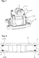
- Figure 1 shows a fluid pump 10 which, in the embodiment shown, is formed as an oil pump for supplying a clutch actuator.
- the fluid pump 10 is also suitable for supplying oil to a gearbox actuator, a cooling system and/or a lubrication system of a drive train.
- the fluid pump 10 is designed as an annular gear pump. It thus comprises a pump unit 12 which works on the principle of an annular gear pump.
- fluid provided to the fluid pump 10 via a fluid inlet 14 is conveyed to a fluid outlet 16 of the fluid pump 10.
- the fluid is pressurised, so the fluid inlet 14 may be described as the suction side and the fluid outlet 16 as the pressure side.
- the pump unit 12 is driven by means of an electric drive unit 18 which is controlled by a control unit 20.
- the pump unit 12 is here received in a first housing part 22 of the fluid pump, and the electrical drive unit 18 in a second housing part 24.
- the first housing part 22 and the second housing part 24 are separate components which are mounted on each other during production of the fluid pump 10.
- the fluid inlet 14 and the fluid outlet 16 are provided in a housing cover 26. This is another component which is separate from the first housing part 22 and second housing part 24.
- the housing cover 26 is thus also mounted on the first housing part 22 during production of the fluid pump.
- the fluid pump 10 is also equipped with a one-piece sealing element 28.
- a total of two sealing lips 28b, 28b, pointing in the direction of the second housing part 24, are provided on the first annular sealing portion 28a.
- the one-piece sealing element 28 furthermore has a second annular sealing portion 28d, which is positioned between the first housing part 22 and the housing cover 26 and in particular seals the first housing part 22 against the housing cover 26.
- the first annular sealing portion 28a and the second annular sealing portion 28d run substantially parallel to one another.
- a total of two sealing lips 28e, 28f, pointing in the direction of the housing cover 26, are provided on the second annular sealing portion 28d and serve for sealing the first housing part 22 against the housing cover 26.
- the two sealing portions 28a, 28d are furthermore connected together via several connecting portions 28g.
- the connecting portions 28g extend substantially perpendicularly to the sealing planes defined by the first sealing portion 28a and the second sealing portion 28d.
- Figures 5 to 8 show a non-definitive number of variants of the one-piece sealing element 28.
- a distance between the first annular sealing portion 28a and the second annual sealing portion 28d may be set via a length of the connecting portions 28g.
- connecting portions 28g which also carry reference sign 30 are offset radially inwardly relative to the other connecting portions 28g.
- the one-piece sealing element 28 is made of fluorocarbon rubber.
- the sealing element 28 is moulded onto the first housing part 22 during production of the fluid pump 10.
- first sealing portion 28a and the second sealing portion 28d are also formed.
- the sealing portions 28a, 28d are arranged on opposite sides of the first housing part 22.
- the sealing element 28 is preferably cohesively and integrally moulded onto the first housing part 22, i.e. the moulding takes place in one process.
- the sealing element 28 is then vulcanized. This gives it elastic properties.
- Both the second housing part 24 and the housing cover 26 are placed on this component at the respective assigned opposite sides.
- the sealing element 28, or more precisely the sealing portions 28a, 28d, is compressed so as to create a reliable seal of the first housing part 22 against the second housing part 24 and against the housing cover 26.
Landscapes
- Engineering & Computer Science (AREA)
- Mechanical Engineering (AREA)
- General Engineering & Computer Science (AREA)
- Details And Applications Of Rotary Liquid Pumps (AREA)
- Details Of Reciprocating Pumps (AREA)
- Physics & Mathematics (AREA)
- Thermal Sciences (AREA)
Abstract
Description
- The invention concerns a fluid pump, in particular an oil pump for supply to a clutch actuator, a gearbox actuator, a lubrication system and/or a cooling system of a drive train, with a pump unit and an electrical drive unit.
- In addition, the invention concerns a method for producing such a fluid pump.
- Such fluid pumps and methods are known from the prior art. Fluid pumps are often fitted to motor vehicles, in particular cars.
- Here, the fluid pumps must firstly function reliably in aggressive environments, i.e. environments with high temperatures and/or shaking or vibrations, over their entire useful life. In addition, the aim is always to produce fluid pumps as cheaply as possible. For this reason, the fluid pumps should be simple to produce. Often, ease of production of the fluid pump conflicts with reliable function over the entire useful life.
- It is therefore an object of the invention to provide a fluid pump which resolves said conflict, i.e. is simple to produce and at the same time functions reliably over its entire useful life.
- This object is achieved by a fluid pump of the type cited initially, in which the pump unit is arranged in a first housing part of the fluid pump, and the electrical drive unit is arranged in a second housing part of the fluid pump which is separate from the first housing part, wherein a one-piece sealing element is provided which seals the first housing part against the second housing part and seals the first housing part against a housing cover arranged on a side opposite the second housing part. Since the pump unit and electrical drive unit are arranged in separate housing parts, they may be preassembled initially with their assigned housing part. Then the two housing parts can be joined together. The housing cover here is also separate from the two housing parts. This allows rapid and simple assembly of the fluid pump. In this context, the one-piece sealing element means that the fluid pump as a whole is constructed from comparatively few components. It also simplifies assembly. The sealing element here fulfils substantially two sealing purposes. Accordingly, the first housing part is reliably sealed against the second housing part, and the first housing part is also reliably sealed against the housing cover. This ensures a long service life of the fluid pump. Advantageously, the housing part may be a thermoset plastic.
- Also, a fluid inlet and/or a fluid outlet of the fluid pump may be provided on the housing cover. Thus the fluid inlet and fluid outlet lie on the same side of the fluid pump. The fluid pump may thus be mounted and connected even in constricted spaces.
- According to one embodiment, the sealing element has a first annular sealing portion which is positioned between the first housing part and the second housing part, and in particular seals the first housing part against the second housing part. Describing the sealing portion as "first" serves solely to designate it precisely. In particular, this term does not imply a number of sealing portions. The general shape of the annular sealing portion is oriented to the shape of the interface between the first housing part and the second housing part. In particular, the sealing portion has a circular ring shape. However, it may also substantially have the shape of an elliptical, rectangular or polygonal ring. The cross-section of the sealing portion should be distinguished from its shape. The cross-section may be circular or rectangular depending on the specific application. As a whole, the first annular sealing portion creates a reliable seal of the first housing part against the second housing part, which leads to a long service life of the fluid pump.
- Alternatively or additionally, the sealing element has a second annular sealing portion which is positioned between the first housing part and the housing cover, and in particular seals the first housing part against the housing cover, in particular wherein the first sealing portion and the second sealing portion run substantially parallel to one another. Describing the sealing portion as "second" again serves solely to designate it precisely. In particular, this term does not imply a number of sealing portions. Otherwise, the effects and advantages which have already been explained with respect to the first sealing portion apply accordingly to the second sealing portion. The only difference is that the second sealing portion acts between the first housing part and the housing cover. A parallel course of the two sealing portions means that the two sealing portions are substantially congruent when viewed perpendicularly to a sealing plane spanned by the first sealing portion or the second sealing portion. Such a sealing element is particularly simple and compact in construction.
- Advantageously, the sealing element has at least one connecting portion which connects the first sealing portion to the second sealing portion, in particular wherein the connecting portion extends substantially perpendicularly to the sealing planes defined by the first sealing portion and the second sealing portion. The connecting portion thus connects the first sealing portion and second sealing portion together integrally. The two sealing portions, more precisely the sealing plane defined by the first sealing portion and the sealing plane defined by the second sealing portion, may have a spacing of more than nil. The connecting portion thus allows the provision of a one-piece sealing element which acts in two sealing planes that are spaced apart from one another. This gives a good compromise between ease of production of the sealing element and the fluid pump, and a long service life of the latter which results in particular from a reliable seal in the sealing planes.
- Also, several connecting portions may be arranged on the periphery of the annular sealing portions. The connecting portions may, but need not, be evenly distributed around the periphery. In particular, the two annular sealing portions are connected together via four to twelve connecting portions. Particularly preferably, six connecting portions are provided. The sealing element thus has a ladder-like form, wherein the two annular sealing portions should be regarded as the side bars and the connecting portions as the rungs.
- With respect to the radial position of the connecting portions relative to the sealing portions, all connecting portions may lie substantially on a same radius. Alternatively, a first group of connecting portions may be further offset radially inwardly than a second group of connecting portions. In this way, the sealing element may be adapted to the geometric conditions inside the fluid pump.
- The sealing element may comprise at least one, in particular two sealing lips pointing in the direction of the second housing part. The sealing lip is preferably provided integrally on the first sealing portion. In the case where two sealing lips are provided, in particular they run parallel. This gives a reliable seal of the first housing part against the second housing part.
- Alternatively or additionally, the sealing element has at least one, in particular two sealing lips pointing in the direction of the housing cover. The sealing lip is preferably provided integrally on the second sealing portion. In the case where two sealing lips are provided, in particular they run parallel. This gives a reliable seal of the first housing part against the housing cover.
- In a variant, the sealing element is made of an elastic mixture or a rubber mixture, in particular fluorocarbon rubber, in particular wherein the sealing element is injection-moulded into a space provided for this on the fluid pump. Elastic mixtures and rubber mixtures are materials with advantageous sealing properties which at the same time are easy to process. Also, by means of this material, durable sealing elements can be produced. This applies in particular to fluorocarbon rubber. By injection-moulding the sealing element into the space provided for this, a reliable sealing effect is achieved at the specified points. In addition, injection-moulding is a comparatively rapid production step. Furthermore, a sealing element may thus be provided in areas with difficult access.
- The object is also achieved by a method of the type cited initially for production of a fluid pump, in which the pump unit is arranged in a first housing part of the fluid pump,
wherein a sealing element for sealing the first housing part against a second housing part, which is separate from the first housing part and in which an electrical drive unit may be provided, and/or for sealing against a housing cover, is moulded onto the first housing part. By moulding the sealing element on, a component is produced comprising the first housing part and the sealing element. This component is designed so that it can be connected tightly to the second housing part and/or the housing cover. This moulding is simple and takes a comparatively short time. Accordingly, the fluid pump can be produced rapidly and easily. - In a variant, the moulding forms a first sealing portion of the sealing element which serves for sealing against the second housing part. Also, a second sealing portion of the sealing element is formed which serves for sealing against the housing cover. In other words, the sealing portions are formed during the moulding process. No further production steps are therefore required. The process for producing the fluid pump may thus take place particularly efficiently.
- Preferably, the first sealing portion and the second sealing portion are arranged on opposite sides of the first housing part, in particular wherein the first sealing portion and the second sealing portion run substantially parallel. Thus fluid pumps may be produced in which the second housing part and the housing cover lie on opposite sides of the first housing part.
- Advantageously, the sealing element is vulcanized after moulding. Thus an elastic behaviour is imposed on the sealing element which guarantees a reliable sealing effect. As an alternative, the sealing element as well as the thermoset plastic of the housing part are vulcanized in a common process step.
- The method for production of a fluid pump is in particular designed to produce a fluid pump according to the invention.
- Preferably, the sealing element is cohesively injection-moulded and/or is integral. This means that only a single injection-moulding process takes place without interruption. In other words, the sealing element is introduced "in one process". The associated production step can thus be performed comparatively quickly.
- Also, the housing cover may be placed on the first housing part with sealing element moulded thereon, and/or the second housing part may be placed on the first housing part with sealing element moulded thereon. Thus the second housing part and/or the housing cover is/are mounted on the component consisting of the first housing part and the sealing element. The sealing effect provided by the sealing element is based in particular on the fact that the sealing element is compressed by application of the second housing part and/or the housing cover.
- The invention is explained below with reference to various exemplary embodiments shown in the attached drawings. The drawings show:
-
Figure 1 a fluid pump according to the invention which is produced by means of a method according to the invention, in a perspective external view, -
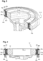
Figure 2a longitudinal section through a part of the fluid pump fromfigure 1 in a side view, -
Figure 3a further longitudinal section through a part of the fluid pump fromfigure 1 in a perspective depiction, wherein parts of a pump unit have been omitted, -
Figure 4a side view of the illustration fromfigure 3 , and -
Figure 5 to figure 8 different variants of a sealing element of the fluid pump fromfigures 1 to 4 . -
Figure 1 shows afluid pump 10 which, in the embodiment shown, is formed as an oil pump for supplying a clutch actuator. - At the same time, the
fluid pump 10 is also suitable for supplying oil to a gearbox actuator, a cooling system and/or a lubrication system of a drive train. - The
fluid pump 10 is designed as an annular gear pump. It thus comprises apump unit 12 which works on the principle of an annular gear pump. - By means of the
pump unit 12, fluid provided to thefluid pump 10 via afluid inlet 14 is conveyed to afluid outlet 16 of thefluid pump 10. The fluid is pressurised, so thefluid inlet 14 may be described as the suction side and thefluid outlet 16 as the pressure side. - The
pump unit 12 is driven by means of an electric drive unit 18 which is controlled by acontrol unit 20. - The
pump unit 12 is here received in afirst housing part 22 of the fluid pump, and the electrical drive unit 18 in asecond housing part 24. - The
first housing part 22 and thesecond housing part 24 are separate components which are mounted on each other during production of thefluid pump 10. - The
fluid inlet 14 and thefluid outlet 16 are provided in ahousing cover 26. This is another component which is separate from thefirst housing part 22 andsecond housing part 24. Thehousing cover 26 is thus also mounted on thefirst housing part 22 during production of the fluid pump. - The
fluid pump 10 is also equipped with a one-piece sealing element 28. - This has a first
annular sealing portion 28a, which is positioned between thefirst housing part 22 and thesecond housing part 24 and in particular seals thefirst housing part 22 against thesecond housing part 24. - For this, a total of two sealing
lips second housing part 24, are provided on the firstannular sealing portion 28a. - The one-
piece sealing element 28 furthermore has a secondannular sealing portion 28d, which is positioned between thefirst housing part 22 and thehousing cover 26 and in particular seals thefirst housing part 22 against thehousing cover 26. - The first
annular sealing portion 28a and the secondannular sealing portion 28d run substantially parallel to one another. - Also, a total of two sealing
lips housing cover 26, are provided on the secondannular sealing portion 28d and serve for sealing thefirst housing part 22 against thehousing cover 26. - The two
sealing portions portions 28g. - The connecting
portions 28g extend substantially perpendicularly to the sealing planes defined by thefirst sealing portion 28a and thesecond sealing portion 28d. -
Figures 5 to 8 show a non-definitive number of variants of the one-piece sealing element 28. - From these examples, it is evident firstly that a distance between the first
annular sealing portion 28a and the second annual sealingportion 28d may be set via a length of the connectingportions 28g. - Secondly, it is clear from the examples of
figures 5 to 8 that the radial positions of the connectingportions 28g on theannular sealing portions - In this context, for example the connecting
portions 28g which also carryreference sign 30 are offset radially inwardly relative to the other connectingportions 28g. - In all variants, the one-
piece sealing element 28 is made of fluorocarbon rubber. - The sealing
element 28 is moulded onto thefirst housing part 22 during production of thefluid pump 10. - During the moulding, the
first sealing portion 28a and thesecond sealing portion 28d are also formed. The sealingportions first housing part 22. - The sealing
element 28 is preferably cohesively and integrally moulded onto thefirst housing part 22, i.e. the moulding takes place in one process. - The sealing
element 28 is then vulcanized. This gives it elastic properties. - This results in a component which comprises the
first housing part 22 and the sealingelement 28. - Both the
second housing part 24 and thehousing cover 26 are placed on this component at the respective assigned opposite sides. Thus the sealingelement 28, or more precisely the sealingportions first housing part 22 against thesecond housing part 24 and against thehousing cover 26.
Claims (14)
- Fluid pump (10), in particular oil pump for supply to a clutch actuator, a gearbox actuator, a lubrication system and/or a cooling system of a drive train, with a pump unit (12) and an electrical drive unit (18), wherein the pump unit (12) is arranged in a first housing part (22) of the fluid pump (10), and the electrical drive unit (18) is arranged in a second housing part (24) of the fluid pump (10) which is separate from the first housing part (22), wherein a one-piece sealing element (28) is provided which seals the first housing part (22) against the second housing part (24) and seals the first housing part (22) against a housing cover (26) arranged on a side opposite the second housing part (24).
- Fluid pump (10) according to claim 1, characterized in that a fluid inlet (14) and/or a fluid outlet (16) of the fluid pump (10) is/are provided on the housing cover (26).
- Fluid pump (10) according to claim 1 or 2, characterized in that the sealing element (28) has a first annular sealing portion (28a), which is positioned between the first housing part (22) and the second housing part (24) and in particular seals the first housing part (22) against the second housing part (24).
- Fluid pump (10) according to any of the preceding claims, characterized in that the sealing element (28) has a second annular sealing portion (28d), which is positioned between the first housing part (22) and the housing cover (26) and in particular seals the first housing part (22) against the housing cover (26), in particular wherein the first sealing portion (28a) and the second sealing portion (28d) run substantially parallel to one another.
- Fluid pump (10) according to claim 3 and 4, characterized in that this sealing element (28) has at least one connecting portion (28g) which connects the first sealing portion (28a) to the second sealing portion (28d), in particular wherein the connecting portion (28g) extends substantially perpendicularly to the sealing planes defined by the first sealing portion (28a) and the second sealing portion (28d).
- Fluid pump (10) according to any of the preceding claims, characterized in that the sealing element (28) has at least one, in particular two sealing lips (28b, 28c) pointing in the direction of the second housing part (24).
- Fluid pump (10) according to any of the preceding claims, characterized in that the sealing element (28) has at least one, in particular two sealing lips (28e, 28f) pointing in the direction of the housing cover (26).
- Fluid pump (10) according to any of the preceding claims, characterized in that the sealing element (28) is made of an elastic mixture or a rubber mixture, in particular a fluorocarbon rubber, in particular wherein the sealing element (28) is injection-moulded into a space provided for this on the fluid pump (10).
- Method for production of a fluid pump (10), in particular an oil pump for supply to a clutch actuator, a gearbox actuator, a lubrication system and/or a cooling system of a drive train, with a pump unit (12) which is arranged in a first housing part (22) of the fluid pump (10),
wherein a sealing element (28) for sealing the first housing part (22) against a second housing part (24), which is separate from the first housing part (22) and in which an electrical drive unit (18) may be provided, and/or for sealing against a housing cover (26), is moulded onto the first housing part (22). - Method according to claim 9, characterized in that by the moulding, a first sealing portion (28a) of the sealing element (28) is formed which serves for sealing against the second housing part (24), and a second sealing portion (28d) of the sealing element (28) is formed which serves for sealing against the housing cover (26).
- Method according to claim 10, characterized in that the first sealing portion (28a) and the second sealing portion (28d) are arranged on opposite sides of the first housing part (22), in particular wherein the first sealing portion (28a) and the second sealing portion (28d) run substantially parallel.
- Method according to any of claims 9 to 11, characterized in that the sealing element (28) is vulcanized after moulding.
- Method according to any of claims 9 to 12, characterized in that the sealing element (28) is cohesively injection-moulded and/or is integral.
- Method according to any of claims 9 to 13, characterized in that the housing cover (26) is placed onto the first housing part (22) with sealing element (28) moulded thereon, and/or
the second housing part (24) is placed on the first housing part (22) with sealing element (28) moulded thereon.
Applications Claiming Priority (1)
| Application Number | Priority Date | Filing Date | Title |
|---|---|---|---|
| DE102019130723.6A DE102019130723A1 (en) | 2019-11-14 | 2019-11-14 | Liquid pump |
Publications (2)
| Publication Number | Publication Date |
|---|---|
| EP3822481A1 true EP3822481A1 (en) | 2021-05-19 |
| EP3822481B1 EP3822481B1 (en) | 2025-01-01 |
Family
ID=73172482
Family Applications (1)
| Application Number | Title | Priority Date | Filing Date |
|---|---|---|---|
| EP20206094.3A Active EP3822481B1 (en) | 2019-11-14 | 2020-11-06 | Fluid pump |
Country Status (6)
| Country | Link |
|---|---|
| US (1) | US12044236B2 (en) |
| EP (1) | EP3822481B1 (en) |
| KR (1) | KR102864709B1 (en) |
| CN (1) | CN112796995A (en) |
| DE (1) | DE102019130723A1 (en) |
| ES (1) | ES3013493T3 (en) |
Families Citing this family (3)
| Publication number | Priority date | Publication date | Assignee | Title |
|---|---|---|---|---|
| DE102016206456B4 (en) * | 2016-04-18 | 2017-11-09 | Continental Automotive Gmbh | Combination comprising a housing and a flange, and arrangement |
| DE102024101196A1 (en) * | 2024-01-16 | 2025-07-17 | Valeo Embrayages | Liquid pump with seal |
| CN120212040B (en) * | 2025-05-28 | 2025-09-02 | 广东美的制冷设备有限公司 | Intermediate plate injection molding assembly, pump body and preparation method of intermediate plate injection molding assembly |
Citations (4)
| Publication number | Priority date | Publication date | Assignee | Title |
|---|---|---|---|---|
| US5639228A (en) * | 1994-10-29 | 1997-06-17 | Pierburg Gmbh | Electrically driven air pump having friction-fit, air-tight seal joints |
| EP2610497A1 (en) * | 2011-12-27 | 2013-07-03 | Grundfos Holding A/S | Pump power unit |
| JP2016540156A (en) * | 2013-11-29 | 2016-12-22 | エフティーイー・オートモーティブ・ゲーエムベーハーF | Electric motor-driven fluid pump, especially for forced lubrication of manual transmissions in motor vehicles |
| US20170009771A1 (en) * | 2013-11-29 | 2017-01-12 | Fte Automotive Gmbh & Co.Kg | Electric motor driven liquid pump, in particular for the forced lubrication of a manual transmission for motor vehicles |
Family Cites Families (10)
| Publication number | Priority date | Publication date | Assignee | Title |
|---|---|---|---|---|
| US6357760B1 (en) * | 2000-05-19 | 2002-03-19 | Michael Doyle | Ring seal |
| DE10059059A1 (en) * | 2000-11-28 | 2002-05-29 | Continental Teves Ag & Co Ohg | Internal gear wheel pump, especially for electrohydraulic braking systems, has seal between housing or cover and axial disc in form of axial seal with supporting ring |
| DE102011001041B9 (en) * | 2010-11-15 | 2014-06-26 | Hnp Mikrosysteme Gmbh | Magnetically driven pump arrangement with a micropump with forced flushing and working method |
| DE102012207078A1 (en) * | 2012-04-27 | 2013-10-31 | Robert Bosch Gmbh | Gear machine with an axial seal, which extends in the region of the radial outer surface of the associated bearing body |
| JP6236958B2 (en) * | 2013-07-24 | 2017-11-29 | 株式会社ジェイテクト | Gear pump |
| JP6369194B2 (en) * | 2014-07-23 | 2018-08-08 | 株式会社ジェイテクト | Electric pump unit |
| DE102015106610A1 (en) * | 2015-04-29 | 2016-11-17 | Ebm-Papst St. Georgen Gmbh & Co. Kg | pump device |
| JP6502811B2 (en) * | 2015-09-18 | 2019-04-17 | アイシン精機株式会社 | Electric pump |
| US9926928B2 (en) * | 2016-01-26 | 2018-03-27 | Brose Fahrzeugteile Gmbh & Co. Kommanditgesellschaft, Wuerzburg | Oil pump |
| DE102019102745A1 (en) * | 2019-02-04 | 2020-08-06 | Schwäbische Hüttenwerke Automotive GmbH | Internal gear pump |
-
2019
- 2019-11-14 DE DE102019130723.6A patent/DE102019130723A1/en active Pending
-
2020
- 2020-11-06 EP EP20206094.3A patent/EP3822481B1/en active Active
- 2020-11-06 ES ES20206094T patent/ES3013493T3/en active Active
- 2020-11-10 US US17/093,827 patent/US12044236B2/en active Active
- 2020-11-11 KR KR1020200150375A patent/KR102864709B1/en active Active
- 2020-11-13 CN CN202011266614.6A patent/CN112796995A/en active Pending
Patent Citations (4)
| Publication number | Priority date | Publication date | Assignee | Title |
|---|---|---|---|---|
| US5639228A (en) * | 1994-10-29 | 1997-06-17 | Pierburg Gmbh | Electrically driven air pump having friction-fit, air-tight seal joints |
| EP2610497A1 (en) * | 2011-12-27 | 2013-07-03 | Grundfos Holding A/S | Pump power unit |
| JP2016540156A (en) * | 2013-11-29 | 2016-12-22 | エフティーイー・オートモーティブ・ゲーエムベーハーF | Electric motor-driven fluid pump, especially for forced lubrication of manual transmissions in motor vehicles |
| US20170009771A1 (en) * | 2013-11-29 | 2017-01-12 | Fte Automotive Gmbh & Co.Kg | Electric motor driven liquid pump, in particular for the forced lubrication of a manual transmission for motor vehicles |
Also Published As
| Publication number | Publication date |
|---|---|
| KR102864709B1 (en) | 2025-09-26 |
| CN112796995A (en) | 2021-05-14 |
| DE102019130723A1 (en) | 2021-05-20 |
| EP3822481B1 (en) | 2025-01-01 |
| KR20210058710A (en) | 2021-05-24 |
| US20210148379A1 (en) | 2021-05-20 |
| US12044236B2 (en) | 2024-07-23 |
| ES3013493T3 (en) | 2025-04-14 |
Similar Documents
| Publication | Publication Date | Title |
|---|---|---|
| EP3822481B1 (en) | Fluid pump | |
| US8910815B2 (en) | Cover for fuel system component and method of making | |
| US20110204577A1 (en) | Radial shaft seal for separating two media | |
| CN105762977B (en) | Motor drive assembly and gear box thereof | |
| KR20130069854A (en) | Seal and method for producing a sealing ring | |
| CN104755356B (en) | Housing for steering gear drive | |
| US9249799B2 (en) | Cylinder housing, in particular pump cylinder housing | |
| US11660561B2 (en) | Filter element with endcap having rigid reinforcing member | |
| EP1600636A3 (en) | Progressing cavity pump or motor | |
| US8047328B1 (en) | Plastic muffler and method for making same | |
| US10422331B2 (en) | One piece diaphragm | |
| JP3962387B2 (en) | Motor housing of electric motor | |
| CN104854385B (en) | Valve wedge for guiding valve | |
| CN102345593A (en) | A support ring for a vehicle fluid assembly and vehicle fluid assembly | |
| CN105545518A (en) | Engine block assembly | |
| KR20180037998A (en) | Vacuum pumps with longitudinal and annular sealing members | |
| CN110894829B (en) | A pressure pump sealing structure, a pressure pump head and a pressure pump | |
| US20180354357A1 (en) | Tank having a stiffening device | |
| US8985082B2 (en) | Engine assembly with pump cavity liner and method of assembling an engine | |
| KR101672890B1 (en) | 2 Liquid Separation Type Oil Seal Unit | |
| JP2019501825A (en) | Brake device | |
| US20160061312A1 (en) | Transmission shipping plug and method of assembly | |
| US8403336B2 (en) | Sealing element for housing of a hand power tool | |
| KR102436355B1 (en) | Compressor | |
| US20070163530A1 (en) | Seal assembly |
Legal Events
| Date | Code | Title | Description |
|---|---|---|---|
| PUAI | Public reference made under article 153(3) epc to a published international application that has entered the european phase |
Free format text: ORIGINAL CODE: 0009012 |
|
| STAA | Information on the status of an ep patent application or granted ep patent |
Free format text: STATUS: REQUEST FOR EXAMINATION WAS MADE |
|
| 17P | Request for examination filed |
Effective date: 20201106 |
|
| AK | Designated contracting states |
Kind code of ref document: A1 Designated state(s): AL AT BE BG CH CY CZ DE DK EE ES FI FR GB GR HR HU IE IS IT LI LT LU LV MC MK MT NL NO PL PT RO RS SE SI SK SM TR |
|
| STAA | Information on the status of an ep patent application or granted ep patent |
Free format text: STATUS: EXAMINATION IS IN PROGRESS |
|
| 17Q | First examination report despatched |
Effective date: 20230206 |
|
| P01 | Opt-out of the competence of the unified patent court (upc) registered |
Effective date: 20230629 |
|
| RAP1 | Party data changed (applicant data changed or rights of an application transferred) |
Owner name: VALEO POWERTRAIN GMBH |
|
| GRAP | Despatch of communication of intention to grant a patent |
Free format text: ORIGINAL CODE: EPIDOSNIGR1 |
|
| STAA | Information on the status of an ep patent application or granted ep patent |
Free format text: STATUS: GRANT OF PATENT IS INTENDED |
|
| GRAS | Grant fee paid |
Free format text: ORIGINAL CODE: EPIDOSNIGR3 |
|
| GRAA | (expected) grant |
Free format text: ORIGINAL CODE: 0009210 |
|
| STAA | Information on the status of an ep patent application or granted ep patent |
Free format text: STATUS: THE PATENT HAS BEEN GRANTED |
|
| INTG | Intention to grant announced |
Effective date: 20241105 |
|
| AK | Designated contracting states |
Kind code of ref document: B1 Designated state(s): AL AT BE BG CH CY CZ DE DK EE ES FI FR GB GR HR HU IE IS IT LI LT LU LV MC MK MT NL NO PL PT RO RS SE SI SK SM TR |
|
| REG | Reference to a national code |
Ref country code: GB Ref legal event code: FG4D |
|
| REG | Reference to a national code |
Ref country code: DE Ref legal event code: R096 Ref document number: 602020043960 Country of ref document: DE |
|
| REG | Reference to a national code |
Ref country code: CH Ref legal event code: EP |
|
| REG | Reference to a national code |
Ref country code: IE Ref legal event code: FG4D |
|
| REG | Reference to a national code |
Ref country code: ES Ref legal event code: FG2A Ref document number: 3013493 Country of ref document: ES Kind code of ref document: T3 Effective date: 20250414 |
|
| REG | Reference to a national code |
Ref country code: LT Ref legal event code: MG9D |
|
| REG | Reference to a national code |
Ref country code: NL Ref legal event code: MP Effective date: 20250101 |
|
| REG | Reference to a national code |
Ref country code: AT Ref legal event code: MK05 Ref document number: 1756495 Country of ref document: AT Kind code of ref document: T Effective date: 20250101 |
|
| PG25 | Lapsed in a contracting state [announced via postgrant information from national office to epo] |
Ref country code: NL Free format text: LAPSE BECAUSE OF FAILURE TO SUBMIT A TRANSLATION OF THE DESCRIPTION OR TO PAY THE FEE WITHIN THE PRESCRIBED TIME-LIMIT Effective date: 20250101 |
|
| PG25 | Lapsed in a contracting state [announced via postgrant information from national office to epo] |
Ref country code: FI Free format text: LAPSE BECAUSE OF FAILURE TO SUBMIT A TRANSLATION OF THE DESCRIPTION OR TO PAY THE FEE WITHIN THE PRESCRIBED TIME-LIMIT Effective date: 20250101 |
|
| PG25 | Lapsed in a contracting state [announced via postgrant information from national office to epo] |
Ref country code: PL Free format text: LAPSE BECAUSE OF FAILURE TO SUBMIT A TRANSLATION OF THE DESCRIPTION OR TO PAY THE FEE WITHIN THE PRESCRIBED TIME-LIMIT Effective date: 20250101 |
|
| PG25 | Lapsed in a contracting state [announced via postgrant information from national office to epo] |
Ref country code: NO Free format text: LAPSE BECAUSE OF FAILURE TO SUBMIT A TRANSLATION OF THE DESCRIPTION OR TO PAY THE FEE WITHIN THE PRESCRIBED TIME-LIMIT Effective date: 20250401 Ref country code: IS Free format text: LAPSE BECAUSE OF FAILURE TO SUBMIT A TRANSLATION OF THE DESCRIPTION OR TO PAY THE FEE WITHIN THE PRESCRIBED TIME-LIMIT Effective date: 20250501 |
|
| PG25 | Lapsed in a contracting state [announced via postgrant information from national office to epo] |
Ref country code: HR Free format text: LAPSE BECAUSE OF FAILURE TO SUBMIT A TRANSLATION OF THE DESCRIPTION OR TO PAY THE FEE WITHIN THE PRESCRIBED TIME-LIMIT Effective date: 20250101 |
|
| PG25 | Lapsed in a contracting state [announced via postgrant information from national office to epo] |
Ref country code: LV Free format text: LAPSE BECAUSE OF FAILURE TO SUBMIT A TRANSLATION OF THE DESCRIPTION OR TO PAY THE FEE WITHIN THE PRESCRIBED TIME-LIMIT Effective date: 20250101 Ref country code: PT Free format text: LAPSE BECAUSE OF FAILURE TO SUBMIT A TRANSLATION OF THE DESCRIPTION OR TO PAY THE FEE WITHIN THE PRESCRIBED TIME-LIMIT Effective date: 20250502 |
|
| PG25 | Lapsed in a contracting state [announced via postgrant information from national office to epo] |
Ref country code: GR Free format text: LAPSE BECAUSE OF FAILURE TO SUBMIT A TRANSLATION OF THE DESCRIPTION OR TO PAY THE FEE WITHIN THE PRESCRIBED TIME-LIMIT Effective date: 20250402 Ref country code: BG Free format text: LAPSE BECAUSE OF FAILURE TO SUBMIT A TRANSLATION OF THE DESCRIPTION OR TO PAY THE FEE WITHIN THE PRESCRIBED TIME-LIMIT Effective date: 20250101 |
|
| PG25 | Lapsed in a contracting state [announced via postgrant information from national office to epo] |
Ref country code: AT Free format text: LAPSE BECAUSE OF FAILURE TO SUBMIT A TRANSLATION OF THE DESCRIPTION OR TO PAY THE FEE WITHIN THE PRESCRIBED TIME-LIMIT Effective date: 20250101 |
|
| PG25 | Lapsed in a contracting state [announced via postgrant information from national office to epo] |
Ref country code: CZ Free format text: LAPSE BECAUSE OF FAILURE TO SUBMIT A TRANSLATION OF THE DESCRIPTION OR TO PAY THE FEE WITHIN THE PRESCRIBED TIME-LIMIT Effective date: 20250101 |
|
| PG25 | Lapsed in a contracting state [announced via postgrant information from national office to epo] |
Ref country code: SE Free format text: LAPSE BECAUSE OF FAILURE TO SUBMIT A TRANSLATION OF THE DESCRIPTION OR TO PAY THE FEE WITHIN THE PRESCRIBED TIME-LIMIT Effective date: 20250101 |
|
| REG | Reference to a national code |
Ref country code: DE Ref legal event code: R097 Ref document number: 602020043960 Country of ref document: DE |
|
| PG25 | Lapsed in a contracting state [announced via postgrant information from national office to epo] |
Ref country code: SM Free format text: LAPSE BECAUSE OF FAILURE TO SUBMIT A TRANSLATION OF THE DESCRIPTION OR TO PAY THE FEE WITHIN THE PRESCRIBED TIME-LIMIT Effective date: 20250101 |
|
| PG25 | Lapsed in a contracting state [announced via postgrant information from national office to epo] |
Ref country code: DK Free format text: LAPSE BECAUSE OF FAILURE TO SUBMIT A TRANSLATION OF THE DESCRIPTION OR TO PAY THE FEE WITHIN THE PRESCRIBED TIME-LIMIT Effective date: 20250101 |
|
| PG25 | Lapsed in a contracting state [announced via postgrant information from national office to epo] |
Ref country code: IT Free format text: LAPSE BECAUSE OF FAILURE TO SUBMIT A TRANSLATION OF THE DESCRIPTION OR TO PAY THE FEE WITHIN THE PRESCRIBED TIME-LIMIT Effective date: 20250101 |
|
| PG25 | Lapsed in a contracting state [announced via postgrant information from national office to epo] |
Ref country code: EE Free format text: LAPSE BECAUSE OF FAILURE TO SUBMIT A TRANSLATION OF THE DESCRIPTION OR TO PAY THE FEE WITHIN THE PRESCRIBED TIME-LIMIT Effective date: 20250101 |
|
| PG25 | Lapsed in a contracting state [announced via postgrant information from national office to epo] |
Ref country code: RO Free format text: LAPSE BECAUSE OF FAILURE TO SUBMIT A TRANSLATION OF THE DESCRIPTION OR TO PAY THE FEE WITHIN THE PRESCRIBED TIME-LIMIT Effective date: 20250101 |
|
| PG25 | Lapsed in a contracting state [announced via postgrant information from national office to epo] |
Ref country code: SK Free format text: LAPSE BECAUSE OF FAILURE TO SUBMIT A TRANSLATION OF THE DESCRIPTION OR TO PAY THE FEE WITHIN THE PRESCRIBED TIME-LIMIT Effective date: 20250101 |
|
| PLBE | No opposition filed within time limit |
Free format text: ORIGINAL CODE: 0009261 |
|
| STAA | Information on the status of an ep patent application or granted ep patent |
Free format text: STATUS: NO OPPOSITION FILED WITHIN TIME LIMIT |
|
| 26N | No opposition filed |
Effective date: 20251002 |
|
| PGFP | Annual fee paid to national office [announced via postgrant information from national office to epo] |
Ref country code: DE Payment date: 20251117 Year of fee payment: 6 |
|
| PGFP | Annual fee paid to national office [announced via postgrant information from national office to epo] |
Ref country code: FR Payment date: 20251128 Year of fee payment: 6 |
|
| PGFP | Annual fee paid to national office [announced via postgrant information from national office to epo] |
Ref country code: ES Payment date: 20251210 Year of fee payment: 6 |