EP3822228A1 - Desalination apparatus for high-saline water - Google Patents
Desalination apparatus for high-saline water Download PDFInfo
- Publication number
- EP3822228A1 EP3822228A1 EP20204281.8A EP20204281A EP3822228A1 EP 3822228 A1 EP3822228 A1 EP 3822228A1 EP 20204281 A EP20204281 A EP 20204281A EP 3822228 A1 EP3822228 A1 EP 3822228A1
- Authority
- EP
- European Patent Office
- Prior art keywords
- water
- stage
- stage module
- swro
- module
- Prior art date
- Legal status (The legal status is an assumption and is not a legal conclusion. Google has not performed a legal analysis and makes no representation as to the accuracy of the status listed.)
- Pending
Links
- XLYOFNOQVPJJNP-UHFFFAOYSA-N water Substances O XLYOFNOQVPJJNP-UHFFFAOYSA-N 0.000 title claims abstract description 326
- 238000010612 desalination reaction Methods 0.000 title claims abstract description 59
- 239000011780 sodium chloride Substances 0.000 title claims abstract description 42
- 238000001223 reverse osmosis Methods 0.000 claims abstract description 50
- 239000012141 concentrate Substances 0.000 claims abstract description 47
- 238000000034 method Methods 0.000 claims abstract description 31
- 230000008569 process Effects 0.000 claims abstract description 27
- 239000000203 mixture Substances 0.000 claims abstract description 4
- 238000011084 recovery Methods 0.000 claims description 80
- 239000000047 product Substances 0.000 claims description 52
- 239000013535 sea water Substances 0.000 claims description 17
- 239000012467 final product Substances 0.000 claims description 10
- 239000012466 permeate Substances 0.000 description 23
- 239000012528 membrane Substances 0.000 description 14
- 238000005265 energy consumption Methods 0.000 description 13
- 230000001965 increasing effect Effects 0.000 description 11
- 239000013505 freshwater Substances 0.000 description 10
- 230000035699 permeability Effects 0.000 description 7
- 238000004519 manufacturing process Methods 0.000 description 5
- 230000009467 reduction Effects 0.000 description 5
- 230000000694 effects Effects 0.000 description 4
- 238000002474 experimental method Methods 0.000 description 4
- 230000003204 osmotic effect Effects 0.000 description 4
- 238000004364 calculation method Methods 0.000 description 3
- 230000008859 change Effects 0.000 description 3
- 238000009826 distribution Methods 0.000 description 3
- 238000001704 evaporation Methods 0.000 description 3
- 150000003839 salts Chemical class 0.000 description 3
- FAPWRFPIFSIZLT-UHFFFAOYSA-M Sodium chloride Chemical compound [Na+].[Cl-] FAPWRFPIFSIZLT-UHFFFAOYSA-M 0.000 description 2
- 238000001914 filtration Methods 0.000 description 2
- 230000004907 flux Effects 0.000 description 2
- 230000006870 function Effects 0.000 description 2
- -1 i.e. Substances 0.000 description 2
- 238000005457 optimization Methods 0.000 description 2
- 238000004088 simulation Methods 0.000 description 2
- 238000013459 approach Methods 0.000 description 1
- 230000015572 biosynthetic process Effects 0.000 description 1
- 238000004422 calculation algorithm Methods 0.000 description 1
- 238000010276 construction Methods 0.000 description 1
- 238000011109 contamination Methods 0.000 description 1
- 230000003247 decreasing effect Effects 0.000 description 1
- 230000006735 deficit Effects 0.000 description 1
- 238000009792 diffusion process Methods 0.000 description 1
- 238000000909 electrodialysis Methods 0.000 description 1
- 230000002708 enhancing effect Effects 0.000 description 1
- 230000008020 evaporation Effects 0.000 description 1
- 238000009434 installation Methods 0.000 description 1
- 230000010354 integration Effects 0.000 description 1
- 238000001728 nano-filtration Methods 0.000 description 1
- 230000008520 organization Effects 0.000 description 1
- 230000010287 polarization Effects 0.000 description 1
- 238000010845 search algorithm Methods 0.000 description 1
- 239000000126 substance Substances 0.000 description 1
- 239000008400 supply water Substances 0.000 description 1
- 238000003911 water pollution Methods 0.000 description 1
Images




Classifications
-
- C—CHEMISTRY; METALLURGY
- C02—TREATMENT OF WATER, WASTE WATER, SEWAGE, OR SLUDGE
- C02F—TREATMENT OF WATER, WASTE WATER, SEWAGE, OR SLUDGE
- C02F1/00—Treatment of water, waste water, or sewage
- C02F1/44—Treatment of water, waste water, or sewage by dialysis, osmosis or reverse osmosis
- C02F1/441—Treatment of water, waste water, or sewage by dialysis, osmosis or reverse osmosis by reverse osmosis
-
- B—PERFORMING OPERATIONS; TRANSPORTING
- B01—PHYSICAL OR CHEMICAL PROCESSES OR APPARATUS IN GENERAL
- B01D—SEPARATION
- B01D61/00—Processes of separation using semi-permeable membranes, e.g. dialysis, osmosis or ultrafiltration; Apparatus, accessories or auxiliary operations specially adapted therefor
- B01D61/02—Reverse osmosis; Hyperfiltration ; Nanofiltration
- B01D61/025—Reverse osmosis; Hyperfiltration
-
- B—PERFORMING OPERATIONS; TRANSPORTING
- B01—PHYSICAL OR CHEMICAL PROCESSES OR APPARATUS IN GENERAL
- B01D—SEPARATION
- B01D61/00—Processes of separation using semi-permeable membranes, e.g. dialysis, osmosis or ultrafiltration; Apparatus, accessories or auxiliary operations specially adapted therefor
- B01D61/02—Reverse osmosis; Hyperfiltration ; Nanofiltration
- B01D61/027—Nanofiltration
-
- B—PERFORMING OPERATIONS; TRANSPORTING
- B01—PHYSICAL OR CHEMICAL PROCESSES OR APPARATUS IN GENERAL
- B01D—SEPARATION
- B01D61/00—Processes of separation using semi-permeable membranes, e.g. dialysis, osmosis or ultrafiltration; Apparatus, accessories or auxiliary operations specially adapted therefor
- B01D61/02—Reverse osmosis; Hyperfiltration ; Nanofiltration
- B01D61/06—Energy recovery
-
- B—PERFORMING OPERATIONS; TRANSPORTING
- B01—PHYSICAL OR CHEMICAL PROCESSES OR APPARATUS IN GENERAL
- B01D—SEPARATION
- B01D2311/00—Details relating to membrane separation process operations and control
- B01D2311/25—Recirculation, recycling or bypass, e.g. recirculation of concentrate into the feed
- B01D2311/252—Recirculation of concentrate
- B01D2311/2523—Recirculation of concentrate to feed side
-
- B—PERFORMING OPERATIONS; TRANSPORTING
- B01—PHYSICAL OR CHEMICAL PROCESSES OR APPARATUS IN GENERAL
- B01D—SEPARATION
- B01D2311/00—Details relating to membrane separation process operations and control
- B01D2311/25—Recirculation, recycling or bypass, e.g. recirculation of concentrate into the feed
- B01D2311/253—Bypassing of feed
-
- B—PERFORMING OPERATIONS; TRANSPORTING
- B01—PHYSICAL OR CHEMICAL PROCESSES OR APPARATUS IN GENERAL
- B01D—SEPARATION
- B01D2313/00—Details relating to membrane modules or apparatus
- B01D2313/24—Specific pressurizing or depressurizing means
- B01D2313/246—Energy recovery means
-
- B—PERFORMING OPERATIONS; TRANSPORTING
- B01—PHYSICAL OR CHEMICAL PROCESSES OR APPARATUS IN GENERAL
- B01D—SEPARATION
- B01D2317/00—Membrane module arrangements within a plant or an apparatus
- B01D2317/02—Elements in series
- B01D2317/022—Reject series
-
- B—PERFORMING OPERATIONS; TRANSPORTING
- B01—PHYSICAL OR CHEMICAL PROCESSES OR APPARATUS IN GENERAL
- B01D—SEPARATION
- B01D2317/00—Membrane module arrangements within a plant or an apparatus
- B01D2317/06—Use of membrane modules of the same kind
-
- B—PERFORMING OPERATIONS; TRANSPORTING
- B01—PHYSICAL OR CHEMICAL PROCESSES OR APPARATUS IN GENERAL
- B01D—SEPARATION
- B01D2317/00—Membrane module arrangements within a plant or an apparatus
- B01D2317/08—Use of membrane modules of different kinds
-
- C—CHEMISTRY; METALLURGY
- C02—TREATMENT OF WATER, WASTE WATER, SEWAGE, OR SLUDGE
- C02F—TREATMENT OF WATER, WASTE WATER, SEWAGE, OR SLUDGE
- C02F2103/00—Nature of the water, waste water, sewage or sludge to be treated
- C02F2103/08—Seawater, e.g. for desalination
-
- C—CHEMISTRY; METALLURGY
- C02—TREATMENT OF WATER, WASTE WATER, SEWAGE, OR SLUDGE
- C02F—TREATMENT OF WATER, WASTE WATER, SEWAGE, OR SLUDGE
- C02F2301/00—General aspects of water treatment
- C02F2301/08—Multistage treatments, e.g. repetition of the same process step under different conditions
-
- C—CHEMISTRY; METALLURGY
- C02—TREATMENT OF WATER, WASTE WATER, SEWAGE, OR SLUDGE
- C02F—TREATMENT OF WATER, WASTE WATER, SEWAGE, OR SLUDGE
- C02F2303/00—Specific treatment goals
- C02F2303/10—Energy recovery
-
- Y—GENERAL TAGGING OF NEW TECHNOLOGICAL DEVELOPMENTS; GENERAL TAGGING OF CROSS-SECTIONAL TECHNOLOGIES SPANNING OVER SEVERAL SECTIONS OF THE IPC; TECHNICAL SUBJECTS COVERED BY FORMER USPC CROSS-REFERENCE ART COLLECTIONS [XRACs] AND DIGESTS
- Y02—TECHNOLOGIES OR APPLICATIONS FOR MITIGATION OR ADAPTATION AGAINST CLIMATE CHANGE
- Y02A—TECHNOLOGIES FOR ADAPTATION TO CLIMATE CHANGE
- Y02A20/00—Water conservation; Efficient water supply; Efficient water use
- Y02A20/124—Water desalination
- Y02A20/131—Reverse-osmosis
-
- Y—GENERAL TAGGING OF NEW TECHNOLOGICAL DEVELOPMENTS; GENERAL TAGGING OF CROSS-SECTIONAL TECHNOLOGIES SPANNING OVER SEVERAL SECTIONS OF THE IPC; TECHNICAL SUBJECTS COVERED BY FORMER USPC CROSS-REFERENCE ART COLLECTIONS [XRACs] AND DIGESTS
- Y02—TECHNOLOGIES OR APPLICATIONS FOR MITIGATION OR ADAPTATION AGAINST CLIMATE CHANGE
- Y02W—CLIMATE CHANGE MITIGATION TECHNOLOGIES RELATED TO WASTEWATER TREATMENT OR WASTE MANAGEMENT
- Y02W10/00—Technologies for wastewater treatment
- Y02W10/30—Wastewater or sewage treatment systems using renewable energies
Definitions
- the present invention relates to a desalination apparatus for high-saline water, in particular a desalination apparatus for high-saline water capable of increasing quality and quantity of the product water during the treatment of high-saline inflow water such as sea water and reducing load of the entire process, thereby increasing energy efficiency.
- NIC National Intelligence Council
- WMO World Meteorological Organization
- Desalination of sea water or desalination of saline-water means that the fresh water is obtained by removing salinity from sea water containing salinity.
- Ways to perform desalination of sea water are evaporation method using water evaporation phenomenon, membrane filtering method using the discrimination and selective permeation of the membrane, etc. and the membrane filtering method is classified into RO (reverse osmosis) and electrodialysis.
- RO reverse osmosis
- water treatment method using reverse osmosis is a way to extract fresh water by arranging a semipermeable membrane therebetween and applying reverse osmosis pressure which is higher than osmosis pressure to sea water.
- the reverse osmosis method is widely being used since it consumes less energy than the evaporation method and easy to control.
- Korean patent 10-1853214 discloses 'a water treatment apparatus using reverse osmosis'.
- Process of desalination from high-saline sea water is generally carried out by pressure-driven SWRO process and it uses hydraulic pressure which is higher than osmosis pressure of inflow water.
- hydraulic pressure of inflow water exceeds osmosis pressure, salinity is removed and then fresh water is produced through a SWRO membrane.
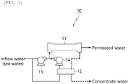
- Fig. 1 shows an example of structures of a single stage SWRO system of prior art.
- the single stage SWRO system comprises a SWRO module and a pressure exchanger.
- Raw water such as sea water is introduced into SWRO module as inflow water by high pressure pump.
- the SWRO module treats the inflow water through the reverse osmosis process and discharges product water and concentrate water.
- Pressure exchanger increase pressure of diverged raw water by using hydraulic pressure of the concentrate water and then mixes the diverged raw water with raw water discharged from the high pressure pump to introduce it as inflow water of the SWRO module.
- Reference number 14 in Fig. 1 indicates a booster pump.
- the recovery rate of the normal single stage SWRO system is less than 50% due to the osmosis pressure of sea water. If high pressure is applied for the high recovery rate, a large amount of water is produced from a SWRO element at the front end, i.e., pressure vessel (hereinafter referred to as 'PV') and the osmosis pressure of the inflow water at the rear end exceeds its hydraulic pressure, resulting in no more production of fresh water.
- 'PV' pressure vessel
- a ratio of the number of PV of the first stage SWRO module to the number of PV of the second stage module is 2:1 and it is similar to a NF (nanofiltration) and BWRO (brackish water reverse osmosis) system.
- NF nanofiltration
- BWRO crackish water reverse osmosis
- the gradual increase of pressure of inflow water exceeding osmosis pressure allows fresh water to be produced at each stage SWRO module, which increases the recovery rate to 60% to 65%.
- Increased recovery rate allows the reduction of the plant size, in particular the reduction of the size of an inlet portion and a pretreatment portion, thereby enabling the reduction of construction cost and operation cost.
- the application of the two stage SWRO system requires higher pressure than the single stage SWRO system, it is not being used generally.
- SWRO desalination plants constructed a two stage SWRO system having a high recovery rate operation.
- the second stage SWRO module is added to the first stage SWRO module in order to increase a plant capacity.
- Such two stage SWRO system increased the recovery rate to 50 to 60% and the necessary hydraulic pressure (70 to 90 bar) depends on the recovery rate.
- stage RO structure is able to decrease SEC of SWRO to energy close to the theoretical minimum energy. This is because the two stage RO makes possible to deliver high pressure to a small volume of inflow water in each stage.
- Advantages of the stage SWRO design for SEC was examined when the system is compared to single-stage SWRO at the same recovery (40%) unlike the real application of two-stage (60%).
- Theoretical background supports the advantages of the two stage at low SEC and enables wide application of the two stage SWRO in the current desalination business.
- the object of the invention is to provide a desalination apparatus for high-saline water capable of increasing quality and quantity of the product water, reducing load of the entire process and increasing energy efficiency, when two stage RO process is applied for the treatment of high-saline inflow water such as sea water.
- a desalination apparatus for high-saline water comprising: a first stage module into which raw water is introduced as a first inflow water and which treats the first inflow water by a reverse osmosis process to discharge a first product water and a first concentrate water; a second stage module into which a second inflow water that is a mixture of the raw water and the first concentrate water is introduced and which treats the second inflow water by a reverse osmosis process to discharge a second product water and a second concentrate water; and a pressure exchanger which increases pressure of the raw water that will be mixed with the first concentrate water by pressure of the second concentrate water; wherein a ratio of the number of pressure vessels constituting the first stage module to the number of pressure vessels constituting the second stage module is in the range of 6:19 to 9:16.
- total recovery rate of the first stage module and the second stage module may be set in a range of 45% to 55%.
- the desalination apparatus may further comprise a third stage module into which the first product water is introduced as a third inflow water, the third stage module being configured to treat the third inflow water by a reverse osmosis process to discharge a third product water and a third concentrate water, wherein the second product water and the third product water are discharged as final product water.
- the desalination apparatus may further comprise a third stage module into which the second product water is introduced as a third inflow water, the third stage module being configured to treat the third inflow water by a reverse osmosis process to discharge a third product water and a third concentrate water, wherein the first product water and the third product water are discharged as final product water.
- the third concentrate water may be mixed with the raw water to dilute the raw water.
- brackish water reverse osmosis may be applied to the third stage module.
- a desalination apparatus for high-saline water comprising: a first stage module into which raw water is introduced as a first inflow water and which treats the first inflow water by a reverse osmosis process to discharge a first product water and a first concentrate water; a second stage module into which the first concentrate water is introduced as a second inflow water and which performs reverse osmosis for the second inflow water to discharge a second product water and a second concentrate water; and a Pelton turbine which generates electric power by means of the second concentrate water; wherein a ratio of the number of pressure vessels constituting the first stage module to the number of pressure vessels constituting the second stage module is in the range of 57:43 to 61:39.
- a total recovery rate of the first stage module and the second stage module may be set in a range of 55% to 70%.
- seawater reverse osmosis may be applied to the first stage module and the second stage module.
- the ratio of the number of pressure vessels constituting the first stage module to the number of pressure vessels constituting the second stage module is set depending on a predetermined total recovery rate of the first stage module and the second stage module.
- the present invention provides a desalination apparatus for high-saline water capable of increasing quantity of fresh water, i.e., product water and reducing salinity.
- a desalination apparatus for high-saline water capable of increasing quality and quantity of the product water, reducing load of the entire process and increasing energy efficiency is provided.
- a desalination apparatus for high-saline water capable of decreasing membrane contamination during reverse osmosis process even in water condition of high salinity, thereby reducing exchange cycle of membrane is provided.
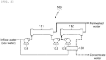
- Fig. 2 represents a structure of a desalination apparatus for high-saline water 100 according to the first embodiment of the present invention.
- the desalination apparatus for high-saline water 100 according to the first embodiment of the present invention comprises a first stage module 111, a second stage module 112, and a pressure exchanger 120.
- Raw water which is a first inflow water is introduced into the first stage module 111.
- raw water is introduced into the first stage module 111 by means of a high pressure pump 131.
- the first stage module 111 carries out a reverse osmosis process for the first inflow water to discharge a first product water (permeated water) and a first concentrate water.
- a second inflow water which is a mixture of raw water and the first concentrate water is introduced into a second stage module 112.
- the second stage module 112 carries out a reverse osmosis process for the second inflow water to discharge a second product water and a second concentrate water.
- a pressure exchanger 120 uses pressure of the second concentrate water to increase pressure of raw water which is not yet mixed With the first concentrate water.
- the first product water from the first stage module 111 and the second product water from the second stage module 112 are produced as final product water.
- Each of the first stage module 111 and the second stage module 112 consists of a plurality of pressure vessel.
- the ratio of the number of the pressure vessels of the first stage module 111 to the number of the pressure vessels of the second stage module 112 is in the range of 6:9 to 9:16.
- the apparatus is operated such that the total recovery rate of the first stage module 111 and the second stage module 112 is set to be in the range of 45% to 55%.
- reference numbers 132 and 133 which were not explained indicate a booster pump.
- Fig. 3 shows a structure of a desalination apparatus for high-saline water 100a according to the second embodiment of the present invention.
- the desalination apparatus for high-saline water 100a according to the second embodiment of the present invention comprises a first stage module 111a, a second stage module 112a, and a Pelton turbine 120a.
- Raw water which is a first inflow water is introduced into the first stage module 111a.
- raw water is introduced into the first stage module 111a by means of a high pressure pump 131a.
- the first stage module 111a carries out a reverse osmosis process for the first inflow water to discharge a first concentrate water.
- the first concentrate water is introduced into the second stage module 112a as a second inflow water.
- the second stage module 112a carries out a reverse osmosis process for the second inflow water to discharge a second product water and a second concentrate water.
- the first product water from the first stage module 111a and the second product water from the second stage module 112a are combined to be final product water.
- the Pelton turbine 120a generates an electric power using hydraulic pressure of the second concentrate water and uses the electric power for the desalination apparatus for high-saline water 100a according to the second embodiment of the present invention, thereby enhancing energy efficiency.
- each of the first stage module 111a and the second stage module 112a consists of a plurality of pressure vessel.
- the first stage module and the second stage module are arranged such that the ratio of the number of the pressure vessels of the first stage module 111a to the number of the pressure vessels of the second stage module 112a is in the range of 57:43 to 61:39.
- the apparatus is operated such that a recovery rate of the second product water produced by the second stage module 112a, i.e., the total recovery rate, is set to be in the range of 45% to 55%.
- reference numbers 132a which was not explained indicate a booster pump.
- SWRO Seawater Reverse Osmosis
- the ratio of the number of pressure vessels consisting the first stage module 111, 111a to the number of pressure vessels consisting the second stage module 112, 112a is determined depending on the total recovery rate of the product water produced by the first stage module 111, 111a and the second stage module 112, 112a.
- the recovery rate will be 40% as can be seen in Fig. 4(a) .
- the system is defined as a two stage SWRO system 100, 110a and the total recovery rate can reach 60% (40% of the first stage module and 20% of the second stage module).
- the recovery rate of the two stage SWRO system 100, 100a as shown in Fig. 4(b) is higher than that of the single stage SWRO system 10 as shown in Fig. 4(a) and it causes energy consumption of the two stage SWRO system 100, 100a.
- the two stage SWRO system 100, 100a in a theoretical study operates with 40% recovery rate as shown in Fig. 4(c) .
- the single stage SWRO system 10 of Fig. 1(a) has the same recovery rate as the two stage SWRO system 100, 100a of Fig. 1(b) , it can be asserted that the two stage SWRO system 100, 110a consumes less energy than the single SWRO system 10.
- J w is a water flux
- J s is a salt flux
- P f is a hydraulic pressure of inflow water
- P p is a hydraulic pressure of permeated water
- CPF is a concentration polarization factor
- ⁇ f is an osmotic pressure of inflow water
- ⁇ p is an osmotic pressure of permeated inflow water
- C f is a salinity of inflow water
- C p a salinity of permeated water
- A is a water permeability
- B is a salt permeability.
- design values recommended by the manufacturing company e.g., hydraulic pressure > 82.7 bar, pressure drop > 1.0 bar, supply water flow > 408 m 3 /d, water permeation > 32.3L/m 2 h
- Permeation quality Q p,system and SWRO system quality C p,system are evaluated by [Formula 3] and [Formula 4] which are the integration of [Formula 1] and [Formula 2] along a membrane area A m .
- [Formula 5] to [Formula 7] are applied for the output of the energy consumption of the SWRO system 10 which depends on the structure.
- E w,single represents energy consumption of the single stage SWRO system 10
- E w,two_PX represents energy consumption of the two stage SWRO system 100 to which the pressure exchanger 120 (hereinafter referred to as PX) is applied, i.e., energy consumption of the desalination apparatus for high-saline water 100 according to the first embodiment of the present invention.
- E w,two_PT represents energy consumption of the two stage SWRO system 100a to which PT is applied, i.e., energy consumption of the desalination apparatus for high-saline water 100a according to the second embodiment of the present
- Flow rate of the inflow water and the concentrate water is represented by Q f and Q c , respectively, and subscripts 1 and 2 indicate the first stage module 111, 111a and the second stage module 112, 112a, respectively.
- Pressure of stream of each stage module is expressed similarly, and pressure P in at the inlet of the SWRO system and pressure P out at the outlet are given as 1 bar.
- mechanical efficiency of the electric motor ⁇ motor is 98%
- the mechanical efficiency ⁇ HPP of pump including a high pressure pump 131 and the mechanical efficiency ⁇ BP of pump including a boost pump are 95% in a basic condition, but ⁇ PT of 90% is applied to some experiment which will be described later.
- Specific energy consumption (hereinafter referred to as SEC) is calculated by [Formula 8].
- SWRO system is designed with a capacity of 100,000 m 3 /d and 1200 PVs are installed such that each PV maintains an average water permeability of 13.35L/m 2 h.
- 1200 PVs and 1800 PVs are considered.
- the permeate flow rate for each stage and the number of PV are determined to evaluate the performance of the two stage SWRO system 100, 100a in such a way to minimize energy consumption.
- the number of PV in the prior-art two stage SWRO system is 1.5 times more than the number of PV in a single stage SWRO system 10 since half the number of the first stage module 111, 111a is added to the second stage module 112, 112a.
- the possibility of RO design can be evaluated fairly only when the number of PV (or membrane) is the same. Therefore, SEC of the single stage SWRO system and SEC of the two stage SWRO system 10, 100, 100a are compared when the number of PV is 1.5 times more and when the number of PV is the same, respectively. SEC is evaluated by using an optimal ratio for each case.
- two stage SWRO system 100, 100a consumes less energy than a single stage SWRO system 10 in the range of a typical recovery rate of SWRO.
- SEC of a single stage SWRO system 10 is 1.99 to 2.15 kWh/m 3 and the lowest SEC is shown at the recovery rate of 38%.
- a two stage SWRO system 100 to which PX is applied consumed 1.89-2.04 kWh/m 3 which is less than SEC of the single stage system in the entire range of recovery rate.
- SEC of the two stage SWRO system 100a to which PT is applied has significantly changed from 2.28 kWh/m 3 to 1.95 kWh/m 3 depending on the recovery rate and the two stage SWRO system 100a to which PT was applied has higher efficiency than the single stage SWRO system 10 at the recovery rate of more than 38%.
- the two stage SWRO system 100a can be obtained for the typical SWRO recovery rate.
- the SEC required for the operation of the two stage SWRO system 100, 100a is higher than the SEC required for that of the single stage SWRO system 10, which can be seen in the Fig. 7(b) .
- SEC does not change since the same condition is applied to the system.
- SEC increases when PVs having the same number as the single stage SWRO system 10 are installed, as can be seen in Fig. 7(b) .
- the two stage SWRO system 100, 100a to which PX and PT are applied indicates 2.10-2.22 kWh/m 3 and 2.97-2.18 kWh/m 3 , respectively, and thus the two stage SWRO system 100, 100a consumed more energy than the single stage SWRO system 10 in the range of given recovery rate.
- the two stage structure is more efficient than the single stage structure.
- the number of PV of the two stage SWRO system 100, 100a is the same as the number of PV of the single stage SWRO system 10
- the average water permeability remains the same.
- the previous theoretical study focuses only the calculation of SEC without considering RO design such as an average water permeability. Therefore, the two stage SWRO system 100, 100a is not profitable in terms of energy consumption in the recovery rate of about 30% as described above.
- the optimal recovery rate which minimizes SEC is influenced by other design factors. Particularly, a high feed flow rate for the stage caused by design results in the increase of the optimal recovery rate.
- initial fresh feed is supplied to the first stage module 111 and the second stage module 112, respectively, and as can be seen in Fig. 2 , the second stage module 112 has inflow water which is the sum of the concentrate water of the first stage module 111 and the initial inflow water.
- the optimal recovery rate of 40% relatively approaches 38% of the single stage.
- the two stage SWRO system 100a to which PT is applied all the inflow water is supplied to the first stage module 111a and the concentrate water of the first stage module 111a is supplied to the second stage module 112a.
- the first stage module 111a has PV whose number is similar to the number of PV of the single stage and the feed flow rate of the first stage module 111a is large.
- the first stage module 111a produces a much more amount of permeated water than the second stage module 112a, thereby the optimal recovery rate is more than 50% and is higher than the single stage SWRO system 10. (see Fig. 7 (b) )
- the two stage SWRO system 100, 100a consumes less energy than the single SWRO system 10. But, when membranes having the same number are used, there is no possibility exceeding the single stage SWRO system 10.
- the arrangement of the two stage SWRO system 100, 100a does not have less energy consumption in the range of the recovery rate of the previous SWRO system.
- the optimal recovery rate differs depending on the design of the SWRO and the optimal recovery rate of the two stage SWRO system 100a having PT is higher than the recovery rate of the previous SWRO system. Therefore, the two stage SWRO system 100, 100a can be realized at the recovery rate higher than the previous SWRO, which will be described later.
- the permeation quality is an important factor for the operation of the SWRO system since it is a criterion for the usability of water. Because the permeation quality depends on the water permeation quantity, it is important to determine the average water permeation quantity for the SWRO system. If the permeate flow rate and PV water quantity are set to be the same for all systems, the average water permeation quantity for the single stage SWRO system 100 is immediately determined, but the water permeation quantity for the two stage SWRO system 100, 100a differs for each stage. Such profile is important since it affects permeation quality of the entire system.
- Permeation quality is determined by the average water permeation quantity of the entire SWRO system, not by the average water permeation quantity of each stage. Referring to Fig. 8(a) , if 1800 PVs are applied to the two stage SWRO system 100, 100a, the permeation quality of the two stage SWRO system is lower than that of the single stage SWRO system 10 to which 1200 PVs are applied.
- the same amount of permeate water is generated from PV having the same number (average water permeate quantity - 13.35 L/m 2 h)
- the permeation quality of the single stage SWRO system 10 in the range of the recovery rate of 30% to 50% is 173-220 mg/L
- the permeation quality of the two stage SWRO system 100, 100a to which PX and PT was applied is 174-214 mg/L and 174-206mg/L, respectively.
- each stage of the two stage SWRO system 100, 100a generates permeate water having different quality, but the permeation quality of the total permeate water (permeate water of the first stage and permeate water of the second stage) from the two stage SWRO system 100, 100a is similar to the permeation quality of the singe stage SWRO system 10 and little bit better. This reflects that the permeation quality is affected by average water permeate quantity of SWRO system regardless of each stage or RO design.
- the two stage SWRO system 100 having PT operates with non-uniform average water permeation quantity for each stage
- the two stage SWRO system 100 having PX provides similar average water permeation quantity for each stage.
- inflow water is divided and supplied to each stage and as shown in Fig. 8(b) , each stage can operate with similar average water permeation quantity (13.81 ⁇ 11.9220.93 L/m 2 h).
- the first stage module 111 produces water with low water permeation quantity and the second stage module 112 produces water with high water permeation quantity (13.20 ⁇ 14.15 L/m 2 h).
- the difference of water permeation quantity increases but the difference is still small. Due to the uniform average water permeation quantity, each stage operates similarly without violating design requirements.
- the first stage module 111a always operates with higher water permeation quantity than the second stage module 112a.
- the average water permeation quantity of the first stage module 111a is of 18.24 ⁇ 14.48 L/m 2 h and the average water permeation quantity of the second stage module 112a is 6.84 ⁇ 11.59 L/m 2 h with the increase of the recovery rate. Since the first stage module 111a operates with very high average water permeation quantity with regard to SWRO, it violates the design requirements in the low recovery rate of 30 ⁇ 36%. However, the second stage module 112a reduces the burden of the first stage module 111a by producing water with high water permeation quantity and thus, SWRO system operates in a stable way at the recovery rate of 37% and more.
- the two stage SWRO system 100, 100a can distribute more water permeation quantity compared to the single stage SWRO system 10.
- the first element of the single stage SWRO system 10 operated with water permeation quantity of 27.99 L/m 2 h at the recovery rate of 40%
- the first element of the two stage SWRO system 110, 110a to which PX and PT were applied provided 20.93 L/m 2 h and 25.53 L/m 2 h, respectively (see Fig. 9(a) ).
- Due to a low water permeation quantity at the first stage module 111, 111a the remaining permeate water was produced at the second stage module 112, 112a.
- water permeation quantity of the eighth element was 26.04 L/m 2 h and 17.49 L/m 2 h, respectively.
- SWRO system operated with high water permeation quantity at the high recovery rate and the two stage SWRO was more appropriate at the high recovery rate, which was caused by the distribution of water permeation quantity and this is because the distribution of water permeation quantity contributes the reduction of fouling.
- Voutchkov's paper “Desalination engineering: planning and design (New York, McGraw Hill 531 Professional, 2012 .)" recites that the two stage SWRO system 100, 100a can be used to form low fouling of the first stage module 111 when the inflow water keeps high concentration of foulant.
- each stage of the two stage SWRO system 100, 100a operated with different average water permeation quantity.
- the difference of the average water permeation quantity between stages was higher than that of the two stage SWRO system 100 to which PX was applied at the low recovery condition, which was a burden to the first stage module 111.
- high average water permeation quantity does not always mean that the water permeation quantity is high at the first element of each stage. Rather, the first element at the single SWRO system 10 provided higher water permeation quantity. That is, the two stage SWRO system 100, 100a has advantages from the water permeation quantity distribution.
- the two stage SWRO system 100, 100a is designed to have a ratio of 2:1 as described above, which means that the ratio of the number of PV of the first stage module 111 to the number of PV of the second stage module 112 is 2:1.
- the ratio of the permeated water quantity produced from the first stage module 111 to the permeated water quantity produced from the second module 112 is 2:1. This is because the two stage SWRO system 100, 100a is used by generally mounting the single stage SWRO system 10 operating with the recovery rate of 40% on the first stage and because the entire recovery rate of the plant is increased to 60% by mounting the second stage module 112 having an additional recovery rate of 20%.
- the first stage module 111a of the two stage SWRO system 100a to which PT is applied has 57% to 61% of the entire PV in the range of recovery rate of 30% to 50% and the ratio of the number of PV is 57:43 to 61:39. Additional PVs were installed in the second stage module 112a instead of the first stage module 111a together with the increase of SWRO recovery rate.
- 2:1 which is the ratio of the number of PV is not an optimal ratio and varied according to SWRO recovery rate and ERD (Energy recovery device).
- the first stage module 111a and the second stage module 112a produced different amount of permeated water and the use of different ERD affected permeate flow rate.
- PX was applied to the two stage SWRO system 100, 100a as ERD
- the SWRO recovery rate 30% to 50%
- 25% to 32% of the entire SWRO permeated water was produced by the first stage module 111
- the remaining 75% to 68% of the target of the permeated water was produced by the second stage module 112 (see Fig. 10(b) ).
- the first stage module 111a of the two stage SWRO system 100a to which PT was applied produced less amount of permeated water (78% to 63%) together with the increase of the recovery rate (30% to 50%). But, more permeate flow rate was obtained by the first stage module than by the second stage module 112a.
- the two stage SWRO system 100 to which PX is applied is a design in which more load is applied to the second stage module 112
- the two stage SWRO system 100a to which PT is applied is a design in which more load is applied to the first stage module 111a.
- the two stage SWRO system 100, 110a is able to distribute more amount of water permeation quantity than the single stage SWRO system 10, but does not have advantages in terms of SEC in the entire SWRO range of the recovery rate of less than 50%.
- SEC of the two stage SWRO system 100, 100a and the single stage SWRO system 10 are similar to each other at the recovery rate of 50% (see Fig. 7(b) ) and further experiment for SEC was performed at the recovery rate of more than 50%.
- the two stage SWRO system 100, 100a has higher efficiency of energy than the single stage SWRO system 10.
- SEC of the single stage SWRO system 10 and the two stage SWRO system 100, 100a is provided at the recovery rate of 30% to 70%.
- the single stage SWRO system 10 consumed less energy than the two stage SWRO system 100, 100a.
- hydraulic pressure cannot exceed osmotic pressure and the increase rate of osmotic pressure is higher than the increase rate of hydraulic pressure. Therefore, it is preferable that only the two stage SWRO system 100, 100a is applied to produce fresh water at the recovery rate of more than 50%.
- the desalination apparatus 100 for high-saline according to the first embodiment of the present invention operates such that the entire recovery rate is set in the rage of 45% to 55% and the desalination apparatus 100a for high-saline according to the second embodiment of the present invention is configured to operate at the recovery rate in the rage of 55% to 70%.
- Fig. 12 shows configuration of a desalination apparatus 100b for high-saline according to the third embodiment of the present invention.
- the desalination apparatus 100b for high-saline according to the third embodiment of the present invention is modified from the first embodiment and may include a first stage module 111b, a second stage module 112b, a pressure exchanger 120b, and a third stage module 113b.
- first stage module 111b corresponds to those of the first embodiment and thus, they will be not described in detail.
- a first product water produced by the first stage module 111b is introduced into the third stage module 113b as a third inflow water. Then, the third stage module 113b performs a reverse osmosis for the third inflow water and discharges a third product water and a third concentrate water. Therefore, a final product water of the desalination apparatus 100b for high-saline according to the third embodiment of the present invention is a second product water and a third product water.
- BWRO Backrackish Water Reverse Osmosis
- the third stage module 113b performs reverse osmosis for the first product water produced by the first stage module 111b one more time, which results in the decrease of salinity of the final product water and the increase of the product water quality.
- Fig. 13 shows configuration of a desalination apparatus 100c for high-saline according to the fourth embodiment of the present invention.
- the desalination apparatus 100c for high-saline according to the fourth embodiment of the present invention is modified from the first embodiment and may include a first stage module 111c, a second stage module 112c, a pressure exchanger 120c, and a third stage module 113c.
- first stage module 111c corresponds to those of the first embodiment and thus, they will be not described in detail.
- a second product water produced by the second stage module 112c is introduced into the third stage module 113c as a third inflow water. Then, the third stage module 113c performs a reverse osmosis for the third inflow water and discharges a third product water and a third concentrate water. Therefore, a final product water of the desalination apparatus 100c for high-saline according to the fourth embodiment of the present invention is a first product water and a third product water.
- BWRO Backrackish Water Reverse Osmosis
- the third stage module 113c performs reverse osmosis for the second product water produced by the second stage module 112c one more time, which results in the decrease of salinity of the final product water and the increase of the product water quality.
- the ratio of pressure vessel and the range of the recovery rate in the third and fourth embodiments correspond to those of the first embodiment.
- the third concentrate water discharged from the third stage module 113b, 113c is mixed with raw water to dilute the raw water, resulting in the overall reduction of process load.
Landscapes
- Chemical & Material Sciences (AREA)
- Engineering & Computer Science (AREA)
- Water Supply & Treatment (AREA)
- Nanotechnology (AREA)
- Chemical Kinetics & Catalysis (AREA)
- Life Sciences & Earth Sciences (AREA)
- Hydrology & Water Resources (AREA)
- Environmental & Geological Engineering (AREA)
- Organic Chemistry (AREA)
- Separation Using Semi-Permeable Membranes (AREA)
Abstract
The present invention relates to a desalination apparatus for high-saline water comprising: a first stage module into which raw water is introduced as a first inflow water and which treats the first inflow water by a reverse osmosis process to discharge a first product water and a first concentrate water; a second stage module into which a second inflow water that is a mixture of the raw water and the first concentrate water is introduced and which treats the second inflow water by a reverse osmosis process to discharge a second product water and a second concentrate water; and a pressure exchanger which increases pressure of the raw water that will be mixed with the first concentrate water by pressure of the second concentrate water; wherein a ratio of the number of pressure vessels constituting the first stage module to the number of pressure vessels constituting the second stage module is in the range of 6:9 to 9:16.
Description
- The present application claims priority to Korean Patent Application No.
10-2020-0039573, filed April 1, 2020 - The present invention relates to a desalination apparatus for high-saline water, in particular a desalination apparatus for high-saline water capable of increasing quality and quantity of the product water during the treatment of high-saline inflow water such as sea water and reducing load of the entire process, thereby increasing energy efficiency.
- Recently, water deficit problem occurs all over the world. About 97% of water on earth is sea water and the remaining fresh water is not sufficient for humans use. Also, climate crisis, desertification, water pollution, etc. worsen the water shortage. For example, it is reported that NIC (National Intelligence Council) in the States reported that more than 3 billion people corresponding half the population in the entire world will live in countries having water shortage in 2015 and WMO (World Meteorological Organization) expects that six hundred and fifty three million to six hundred and four million people will experience water shortage problem in 2025 and 2.43 billion people will experience water shortage problem in 2050.
- To solve the water shortage problem, use of bank-filtered water or underwater, rainmaking, etc. are suggested, but desalination of sea water which is infinite resource is emerged as the most practical way to solve essential problems.
- Desalination of sea water or desalination of saline-water (hereinafter referred to as desalination of sea water) means that the fresh water is obtained by removing salinity from sea water containing salinity.
- Ways to perform desalination of sea water are evaporation method using water evaporation phenomenon, membrane filtering method using the discrimination and selective permeation of the membrane, etc. and the membrane filtering method is classified into RO (reverse osmosis) and electrodialysis.
- In particular, water treatment method using reverse osmosis is a way to extract fresh water by arranging a semipermeable membrane therebetween and applying reverse osmosis pressure which is higher than osmosis pressure to sea water. The reverse osmosis method is widely being used since it consumes less energy than the evaporation method and easy to control. For example, Korean patent
10-1853214 - However, places requiring the desalination apparatus mostly have high salinity of inflow water and high temperature. In this water condition, the amount of water obtained by the normal reverse osmosis apparatus is very limited. In other words, a recovery rate is low. Also, salinity of product water is high since water is produced from high-saline inflow water.
- Process of desalination from high-saline sea water is generally carried out by pressure-driven SWRO process and it uses hydraulic pressure which is higher than osmosis pressure of inflow water. When hydraulic pressure of inflow water exceeds osmosis pressure, salinity is removed and then fresh water is produced through a SWRO membrane.
-
Fig. 1 shows an example of structures of a single stage SWRO system of prior art. As shown inFig. 1 , the single stage SWRO system comprises a SWRO module and a pressure exchanger. Raw water such as sea water is introduced into SWRO module as inflow water by high pressure pump. The SWRO module treats the inflow water through the reverse osmosis process and discharges product water and concentrate water. Pressure exchanger increase pressure of diverged raw water by using hydraulic pressure of the concentrate water and then mixes the diverged raw water with raw water discharged from the high pressure pump to introduce it as inflow water of the SWRO module.Reference number 14 inFig. 1 indicates a booster pump. - The recovery rate of the normal single stage SWRO system is less than 50% due to the osmosis pressure of sea water. If high pressure is applied for the high recovery rate, a large amount of water is produced from a SWRO element at the front end, i.e., pressure vessel (hereinafter referred to as 'PV') and the osmosis pressure of the inflow water at the rear end exceeds its hydraulic pressure, resulting in no more production of fresh water.
- To increase the recovery rate of SWRO system, a two stage design was developed and it is configured to introduce concentrate water of the first stage SWRO module into the second stage SWRO module, thereby producing more amount of fresh water.
- For a normal two stage SWRO system, a ratio of the number of PV of the first stage SWRO module to the number of PV of the second stage module is 2:1 and it is similar to a NF (nanofiltration) and BWRO (brackish water reverse osmosis) system. When two stage SWRO system is used, the gradual increase of pressure of inflow water exceeding osmosis pressure allows fresh water to be produced at each stage SWRO module, which increases the recovery rate to 60% to 65%. Increased recovery rate allows the reduction of the plant size, in particular the reduction of the size of an inlet portion and a pretreatment portion, thereby enabling the reduction of construction cost and operation cost. Meanwhile, since the application of the two stage SWRO system requires higher pressure than the single stage SWRO system, it is not being used generally.
- Hence, several SWRO desalination plants constructed a two stage SWRO system having a high recovery rate operation. For the overall SWRO desalination plant to which the two stage SWRO system, the second stage SWRO module is added to the first stage SWRO module in order to increase a plant capacity. Such two stage SWRO system increased the recovery rate to 50 to 60% and the necessary hydraulic pressure (70 to 90 bar) depends on the recovery rate.
- Due to extremely high pressure of inflow water at the second stage SWRO module, devices having resistance to high pressure should be installed. This increases equipment costs compared to the operations under normal pressure. Also, the installation of additional stage and other equipment increases cost of capital. Moreover, specific energy consumption (SEC) the two stage SWRO system is high due to the high recovery rate. Since desalination business recently focuses on SEC rather than high recovery rate, current SWRO desalination plant generally use a single stage instead of two stages.
- Recently, theoretical study reveals that stage RO structure is able to decrease SEC of SWRO to energy close to the theoretical minimum energy. This is because the two stage RO makes possible to deliver high pressure to a small volume of inflow water in each stage. Advantages of the stage SWRO design for SEC was examined when the system is compared to single-stage SWRO at the same recovery (40%) unlike the real application of two-stage (60%). Theoretical background supports the advantages of the two stage at low SEC and enables wide application of the two stage SWRO in the current desalination business.
- However, the above study does not fully support that the suggested two stage SWRO can be realized over the single stage SWRO. In fact, theoretical study focused only the energy consumption and did not consider more practical perspective of SWRO such as quality of fresh water or other operation issues. Moreover, when SEC is compared, the number of PV of the two stage RO is higher than the number of PV of the single stage RO, which is due to the status of other equipment. Additionally, the evaluated SEC was not optimized since the flow rate and the number of PV were determined without the optimized consideration, but PV was arranged in a ratio of 2:1 based on experience. In other words, the average flow rate and recovery rate at each stage were not determined systemically. Regarding the calculation of SEC, by the application of a thermodynamic model and a simple RO model, the two stage SWRO cannot be realized.
- Accordingly, the present invention is provided to solve the above problems. The object of the invention is to provide a desalination apparatus for high-saline water capable of increasing quality and quantity of the product water, reducing load of the entire process and increasing energy efficiency, when two stage RO process is applied for the treatment of high-saline inflow water such as sea water.
- The above object is accomplished by a desalination apparatus for high-saline water comprising: a first stage module into which raw water is introduced as a first inflow water and which treats the first inflow water by a reverse osmosis process to discharge a first product water and a first concentrate water; a second stage module into which a second inflow water that is a mixture of the raw water and the first concentrate water is introduced and which treats the second inflow water by a reverse osmosis process to discharge a second product water and a second concentrate water; and a pressure exchanger which increases pressure of the raw water that will be mixed with the first concentrate water by pressure of the second concentrate water; wherein a ratio of the number of pressure vessels constituting the first stage module to the number of pressure vessels constituting the second stage module is in the range of 6:19 to 9:16.
- Here, total recovery rate of the first stage module and the second stage module may be set in a range of 45% to 55%.
- Also, the desalination apparatus may further comprise a third stage module into which the first product water is introduced as a third inflow water, the third stage module being configured to treat the third inflow water by a reverse osmosis process to discharge a third product water and a third concentrate water, wherein the second product water and the third product water are discharged as final product water.
- Also, the desalination apparatus may further comprise a third stage module into which the second product water is introduced as a third inflow water, the third stage module being configured to treat the third inflow water by a reverse osmosis process to discharge a third product water and a third concentrate water, wherein the first product water and the third product water are discharged as final product water.
- Also, the third concentrate water may be mixed with the raw water to dilute the raw water.
- Also, brackish water reverse osmosis (BWRO) may be applied to the third stage module.
- Moreover, the above object may be also accomplished by a desalination apparatus for high-saline water according to another embodiment of the invention comprising: a first stage module into which raw water is introduced as a first inflow water and which treats the first inflow water by a reverse osmosis process to discharge a first product water and a first concentrate water; a second stage module into which the first concentrate water is introduced as a second inflow water and which performs reverse osmosis for the second inflow water to discharge a second product water and a second concentrate water; and a Pelton turbine which generates electric power by means of the second concentrate water; wherein a ratio of the number of pressure vessels constituting the first stage module to the number of pressure vessels constituting the second stage module is in the range of 57:43 to 61:39.
- Here, a total recovery rate of the first stage module and the second stage module may be set in a range of 55% to 70%.
- Also, seawater reverse osmosis (SWRO) may be applied to the first stage module and the second stage module.
- Also, the ratio of the number of pressure vessels constituting the first stage module to the number of pressure vessels constituting the second stage module is set depending on a predetermined total recovery rate of the first stage module and the second stage module.
- According to the above arrangement, for high saline inflow water such as sea water, the present invention provides a desalination apparatus for high-saline water capable of increasing quantity of fresh water, i.e., product water and reducing salinity.
- Also, according to the present invention, a desalination apparatus for high-saline water capable of increasing quality and quantity of the product water, reducing load of the entire process and increasing energy efficiency is provided.
- Also, according to the present invention, a desalination apparatus for high-saline water capable of decreasing membrane contamination during reverse osmosis process even in water condition of high salinity, thereby reducing exchange cycle of membrane is provided.
-
-
Fig. 1 shows an example of configuration of a single stage SWRO system of prior art. -
Fig. 2 shows configuration of a desalination apparatus for high-saline water according to the first embodiment of the present invention. -
Fig. 3 shows configuration of a desalination apparatus for high-saline water according to the second embodiment of the present invention. -
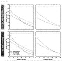
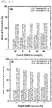
Figs. 4 to 11 represent theoretical and experimental effects for the desalination apparatus for high-saline water according to the first and second embodiments of the present invention. -
Fig. 12 shows configuration of a desalination apparatus for high-saline according to the third embodiment of the present invention. -
Fig. 13 shows configuration of a desalination apparatus for high-saline according to the fourth embodiment of the present invention. - Hereinafter, embodiments for the invention will be described referring to the attached drawing.
-
Fig. 2 represents a structure of a desalination apparatus for high-saline water 100 according to the first embodiment of the present invention. Referring toFig. 2 , the desalination apparatus for high-saline water 100 according to the first embodiment of the present invention comprises afirst stage module 111, asecond stage module 112, and apressure exchanger 120. - Raw water which is a first inflow water is introduced into the
first stage module 111. Here, raw water is introduced into thefirst stage module 111 by means of ahigh pressure pump 131. Thefirst stage module 111 carries out a reverse osmosis process for the first inflow water to discharge a first product water (permeated water) and a first concentrate water. - A second inflow water which is a mixture of raw water and the first concentrate water is introduced into a
second stage module 112. Thesecond stage module 112 carries out a reverse osmosis process for the second inflow water to discharge a second product water and a second concentrate water. Here, apressure exchanger 120 uses pressure of the second concentrate water to increase pressure of raw water which is not yet mixed With the first concentrate water. - According to the first embodiment, the first product water from the
first stage module 111 and the second product water from thesecond stage module 112 are produced as final product water. - Each of the
first stage module 111 and thesecond stage module 112 consists of a plurality of pressure vessel. In an example, the ratio of the number of the pressure vessels of thefirst stage module 111 to the number of the pressure vessels of thesecond stage module 112 is in the range of 6:9 to 9:16. Also, the apparatus is operated such that the total recovery rate of thefirst stage module 111 and thesecond stage module 112 is set to be in the range of 45% to 55%. - Also, in
Fig. 2 ,reference numbers -
Fig. 3 shows a structure of a desalination apparatus for high-saline water 100a according to the second embodiment of the present invention. Referring toFig. 3 , the desalination apparatus for high-saline water 100a according to the second embodiment of the present invention comprises afirst stage module 111a, asecond stage module 112a, and aPelton turbine 120a. - Raw water which is a first inflow water is introduced into the
first stage module 111a. Here, raw water is introduced into thefirst stage module 111a by means of ahigh pressure pump 131a. Thefirst stage module 111a carries out a reverse osmosis process for the first inflow water to discharge a first concentrate water. - The first concentrate water is introduced into the
second stage module 112a as a second inflow water. Thesecond stage module 112a carries out a reverse osmosis process for the second inflow water to discharge a second product water and a second concentrate water. - According to the second embodiment, the first product water from the
first stage module 111a and the second product water from thesecond stage module 112a are combined to be final product water. - The
Pelton turbine 120a generates an electric power using hydraulic pressure of the second concentrate water and uses the electric power for the desalination apparatus for high-saline water 100a according to the second embodiment of the present invention, thereby enhancing energy efficiency. - Here, each of the
first stage module 111a and thesecond stage module 112a consists of a plurality of pressure vessel. In an example, the first stage module and the second stage module are arranged such that the ratio of the number of the pressure vessels of thefirst stage module 111a to the number of the pressure vessels of thesecond stage module 112a is in the range of 57:43 to 61:39. Also, the apparatus is operated such that a recovery rate of the second product water produced by thesecond stage module 112a, i.e., the total recovery rate, is set to be in the range of 45% to 55%. - In
Fig. 3 ,reference numbers 132a which was not explained indicate a booster pump. - In the first and second embodiments, to deal with the high saline. SWRO (Seawater Reverse Osmosis) may be applied to the
first stage module second stage module - Also, the ratio of the number of pressure vessels consisting the
first stage module second stage module first stage module second stage module - Hereinafter, referring to
Figs. 4 to 11 , theoretical and experimental effects for the desalination apparatus for high-saline water - As shown in
Fig. 1 , in case of a singlestage SWRO system 10 of prior art, assuming that about 40% of the inflow rate is converted into permeated water, i.e., product water, the recovery rate will be 40% as can be seen inFig. 4(a) . In order to increase the recovery rate, like the general twostage SWRO system 100, 110a, if thesecond stage module stage SWRO system 10 as shown inFig. 4(b) , the system is defined as a twostage SWRO system 100, 110a and the total recovery rate can reach 60% (40% of the first stage module and 20% of the second stage module). - Here, the recovery rate of the two
stage SWRO system Fig. 4(b) is higher than that of the singlestage SWRO system 10 as shown inFig. 4(a) and it causes energy consumption of the twostage SWRO system stage SWRO system stage SWRO system Fig. 4(c) . When the singlestage SWRO system 10 ofFig. 1(a) has the same recovery rate as the twostage SWRO system Fig. 1(b) , it can be asserted that the twostage SWRO system 100, 110a consumes less energy than thesingle SWRO system 10. Accordingly, as described above, when the twostage SWRO system saline water - Considering the practical application of the two stage SWRO which uses
Pelton turbine 120a (hereinafter referred to as PT) as the energy recovery device as in the second embodiment, the efficiency of PT is given with 95% and 90%, respectively. The performance of SWRO process is evaluated based on the solution-diffusion model as shown in [Formula 1] and [Formula 2].

- Here, Jw is a water flux, Js is a salt flux, Pf is a hydraulic pressure of inflow water, Pp is a hydraulic pressure of permeated water, CPF is a concentration polarization factor, πf is an osmotic pressure of inflow water, πp is an osmotic pressure of permeated inflow water, Cf is a salinity of inflow water, Cp a salinity of permeated water, A is a water permeability, and B is a salt permeability.
- The program for the simulation provided a high accuracy (R2 = 0.9998) with the result estimated from a program Q+ version 2.4 provided by a membrane manufacturing company, and the maximum differences in the pressure and the permeate quality provided in the range of the recovery rate were 0.7 bar and 2 mg/L, respectively. If the operating condition violates design values recommended by the manufacturing company (e.g., hydraulic pressure > 82.7 bar, pressure drop > 1.0 bar, supply water flow > 408 m3/d, water permeation > 32.3L/m2h), the program provides a warning sign which is indicated by red dots in the figure.
- Permeation quality Qp,system and SWRO system quality Cp,system are evaluated by [Formula 3] and [Formula 4] which are the integration of [Formula 1] and [Formula 2] along a membrane area Am . [Formula 5] to [Formula 7] are applied for the output of the energy consumption of the
SWRO system 10 which depends on the structure. Ew,single represents energy consumption of the singlestage SWRO system 10, and Ew,two_PX represents energy consumption of the twostage SWRO system 100 to which the pressure exchanger 120 (hereinafter referred to as PX) is applied, i.e., energy consumption of the desalination apparatus for high-saline water 100 according to the first embodiment of the present invention. Ew,two_PT represents energy consumption of the twostage SWRO system 100a to which PT is applied, i.e., energy consumption of the desalination apparatus for high-saline water 100a according to the second embodiment of the present. - Flow rate of the inflow water and the concentrate water is represented by Qf and Qc, respectively, and
subscripts 1 and 2 indicate thefirst stage module second stage module - Also, mechanical efficiency of the electric motor ηmotor is 98%,
The mechanical efficiency ηHPP of pump including ahigh pressure pump 131 and the mechanical efficiency ηBP of pump including a boost pump are 95% in a basic condition, but ηPT of 90% is applied to some experiment which will be described later. Specific energy consumption (hereinafter referred to as SEC) is calculated by [Formula 8].


- SWRO system is designed with a capacity of 100,000 m3/d and 1200 PVs are installed such that each PV maintains an average water permeability of 13.35L/m2h. For two
stage SWRO system stage SWRO system 10, both 1200 PVs and 1800 PVs are considered. However, the permeate flow rate for each stage and the number of PV are determined to evaluate the performance of the twostage SWRO system - Therefore, the objective function of harmony search and constraint condition are given as [Formula 9] and [Formula 10].


- Since objective function is uncontinuous and non-differentiatable, optimal decision variable is very complicated to use a common optimization technique and thus, the harmony search as metaheuristic algorithm is applied in order to find efficiently decision variables having the balance between diversification and intensification.
- In the present invention, best decision variables can be obtained within 500 iterations (see
Fig. 6 ), the harmony search algorithm can reduce iteration time compared to standard calculation time (24000) required for the optimization. Parameters used for the harmony search are shown in [Table 1].[Table 1] Parameters used in the harmony search (HS). Parameters Value Harmony memory size (HMS) [-] 10 Bandwidth (BW) for permeate flow rate [m3/d] 1000 Bandwidth (BW) for PV numbers [-] 5 Harmony memory considering rate (HMCR) [-] 0.7 Pitch adjusting rate (PAR) [-] 0.3 - The number of PV in the prior-art two stage SWRO system is 1.5 times more than the number of PV in a single
stage SWRO system 10 since half the number of thefirst stage module second stage module stage SWRO system - In
Fig. 7 (a) , twostage SWRO system stage SWRO system 10 in the range of a typical recovery rate of SWRO. SEC of a singlestage SWRO system 10 is 1.99 to 2.15 kWh/m3 and the lowest SEC is shown at the recovery rate of 38%. Meanwhile, as in the first embodiment of the present invention, during the production of permeated water, a twostage SWRO system 100 to which PX is applied consumed 1.89-2.04 kWh/m3 which is less than SEC of the single stage system in the entire range of recovery rate. However, as in the second embodiment of the present invention, SEC of the twostage SWRO system 100a to which PT is applied has significantly changed from 2.28 kWh/m3 to 1.95 kWh/m3 depending on the recovery rate and the twostage SWRO system 100a to which PT was applied has higher efficiency than the singlestage SWRO system 10 at the recovery rate of more than 38%. Considering SWRO plant operating in the range of 40% to 45%, the twostage SWRO system 100a can be obtained for the typical SWRO recovery rate. - But, when the number of PV is the same, the SEC required for the operation of the two
stage SWRO system stage SWRO system 10, which can be seen in theFig. 7(b) . For the singlestage SWRO system 10, SEC does not change since the same condition is applied to the system. Meanwhile, for the twostage SWRO system stage SWRO system 10 are installed, as can be seen inFig. 7(b) . The twostage SWRO system stage SWRO system stage SWRO system 10 in the range of given recovery rate. Such result is not in accordance with the assertion that the two stage structure is more efficient than the single stage structure. In fact, when the number of PV of the twostage SWRO system stage SWRO system 10, the average water permeability remains the same. Meanwhile, the previous theoretical study focuses only the calculation of SEC without considering RO design such as an average water permeability. Therefore, the twostage SWRO system - Meanwhile, the optimal recovery rate which minimizes SEC is influenced by other design factors. Particularly, a high feed flow rate for the stage caused by design results in the increase of the optimal recovery rate. In the two
stage SWRO system 100 to which PX is applied, initial fresh feed is supplied to thefirst stage module 111 and thesecond stage module 112, respectively, and as can be seen inFig. 2 , thesecond stage module 112 has inflow water which is the sum of the concentrate water of thefirst stage module 111 and the initial inflow water. - Since the initial inflow water is divided and supplied to the respective stage module, the feed flow rate for each stage module is not that high compared to the single stage. Therefore, as shown in
Fig. 7 (b) , the optimal recovery rate of 40% relatively approaches 38% of the single stage. Meanwhile, in the twostage SWRO system 100a to which PT is applied, all the inflow water is supplied to thefirst stage module 111a and the concentrate water of thefirst stage module 111a is supplied to thesecond stage module 112a. However, in the twostage SWRO system 100a to which PT is applied, thefirst stage module 111a has PV whose number is similar to the number of PV of the single stage and the feed flow rate of thefirst stage module 111a is large. For the twostage SWRO system 100a to which PT is applied, thefirst stage module 111a produces a much more amount of permeated water than thesecond stage module 112a, thereby the optimal recovery rate is more than 50% and is higher than the singlestage SWRO system 10. (seeFig. 7 (b) ) - When more membranes are installed, the two
stage SWRO system single SWRO system 10. But, when membranes having the same number are used, there is no possibility exceeding the singlestage SWRO system 10. - In other words, the arrangement of the two
stage SWRO system stage SWRO system 100a having PT is higher than the recovery rate of the previous SWRO system. Therefore, the twostage SWRO system - Meanwhile, the permeation quality is an important factor for the operation of the SWRO system since it is a criterion for the usability of water. Because the permeation quality depends on the water permeation quantity, it is important to determine the average water permeation quantity for the SWRO system. If the permeate flow rate and PV water quantity are set to be the same for all systems, the average water permeation quantity for the single
stage SWRO system 100 is immediately determined, but the water permeation quantity for the twostage SWRO system - Also, a high-flux operation has weakness as to fouling formation at the membrane, which weakens the performance. Therefore, the permeation quality and the average water permeation quantity for the two
stage SWRO system - Permeation quality is determined by the average water permeation quantity of the entire SWRO system, not by the average water permeation quantity of each stage. Referring to
Fig. 8(a) , if 1800 PVs are applied to the twostage SWRO system stage SWRO system 10 to which 1200 PVs are applied. However, the same amount of permeate water is generated from PV having the same number (average water permeate quantity - 13.35 L/m2h), the permeation quality of the singlestage SWRO system 10 in the range of the recovery rate of 30% to 50% is 173-220 mg/L and the permeation quality of the twostage SWRO system stage SWRO system stage SWRO system stage SWRO system 10 and little bit better. This reflects that the permeation quality is affected by average water permeate quantity of SWRO system regardless of each stage or RO design. - While the two
stage SWRO system 100a having PT operates with non-uniform average water permeation quantity for each stage, the twostage SWRO system 100 having PX provides similar average water permeation quantity for each stage. For the twostage SWRO system 100 having PX, inflow water is divided and supplied to each stage and as shown inFig. 8(b) , each stage can operate with similar average water permeation quantity (13.81∼11.9220.93 L/m2h). With the increase of recovery quantity, thefirst stage module 111 produces water with low water permeation quantity and thesecond stage module 112 produces water with high water permeation quantity (13.20∼14.15 L/m2h). In this regard, the difference of water permeation quantity increases but the difference is still small. Due to the uniform average water permeation quantity, each stage operates similarly without violating design requirements. - Meanwhile, for the two
stage SWRO system 100a having PT, thefirst stage module 111a always operates with higher water permeation quantity than thesecond stage module 112a. The average water permeation quantity of thefirst stage module 111a is of 18.24∼14.48 L/m2h and the average water permeation quantity of thesecond stage module 112a is 6.84∼11.59 L/m2h with the increase of the recovery rate. Since thefirst stage module 111a operates with very high average water permeation quantity with regard to SWRO, it violates the design requirements in the low recovery rate of 30∼36%. However, thesecond stage module 112a reduces the burden of thefirst stage module 111a by producing water with high water permeation quantity and thus, SWRO system operates in a stable way at the recovery rate of 37% and more. - The two
stage SWRO system stage SWRO system 10. When the first element of the singlestage SWRO system 10 operated with water permeation quantity of 27.99 L/m2h at the recovery rate of 40%, the first element of the two stage SWRO system 110, 110a to which PX and PT were applied provided 20.93 L/m2h and 25.53 L/m2h, respectively (seeFig. 9(a) ). Due to a low water permeation quantity at thefirst stage module second stage module - With the increase of the recovery rate, a large amount of permeate water was produced and much water permeation quantity was generated along PV. At the recovery rate of 45% (see
Fig. 9(b) ), water permeation quantity of 31.50 L/m2h was observed at the first element and it was close to the limit of recommended water permeation quantity of 32.30 L/m2h. Meanwhile, water permeation quantity at the first element was 22.07 L/m2h and 25.37 L/m2h and water permeation quantity at the eighth element of the two stage to which PX and PT were applied was 28.41 L/m2h and 19.97 L/m2h. SWRO system operated with high water permeation quantity at the high recovery rate and the two stage SWRO was more appropriate at the high recovery rate, which was caused by the distribution of water permeation quantity and this is because the distribution of water permeation quantity contributes the reduction of fouling. Similarly, Voutchkov's paper "Desalination engineering: planning and design (New York, McGraw Hill 531 Professional, 2012.)" recites that the twostage SWRO system first stage module 111 when the inflow water keeps high concentration of foulant. - As long as the average water permeation quantity of the entire SWRO system does not change, the permeation quality remained the same regardless of RO design. Even though the average water permeation quantity was the same for the entire SWRO system, each stage of the two
stage SWRO system stage SWRO system 100a to which PT was applied, the difference of the average water permeation quantity between stages was higher than that of the twostage SWRO system 100 to which PX was applied at the low recovery condition, which was a burden to thefirst stage module 111. However, high average water permeation quantity does not always mean that the water permeation quantity is high at the first element of each stage. Rather, the first element at thesingle SWRO system 10 provided higher water permeation quantity. That is, the twostage SWRO system - In general, the two
stage SWRO system first stage module 111 to the number of PV of thesecond stage module 112 is 2:1. Generally, the ratio of the permeated water quantity produced from thefirst stage module 111 to the permeated water quantity produced from thesecond module 112 is 2:1. This is because the twostage SWRO system stage SWRO system 10 operating with the recovery rate of 40% on the first stage and because the entire recovery rate of the plant is increased to 60% by mounting thesecond stage module 112 having an additional recovery rate of 20%. - However, the ratio by the optimal design which minimizes SEC and increases the recovery rate is not 2:1, which will be described in the below in detail.
- For two
stage SWRO system second stage module 112 when the SWRO system is equipped with PX, while in thefirst stage module 111a when with PT. - In the two
stage SWRO system 100 to which PX is applied, thefirst stage module 111 has 24% to 36% of the entire PV, resulting in that the entire SWRO recovery rate increased from 30% to 50% (seeFig. 10(a) ). Therefore, for the twostage SWRO system 100 to which PX is applied, i.e., thedesalination apparatus 100 for high-saline water according to the first embodiment of the present invention, the ratio of the number of PV is 24:76 to 36:64 (=6:19 to 9:16) and more PVs are installed in thesecond stage module 112. - In contrast, the
first stage module 111a of the twostage SWRO system 100a to which PT is applied has 57% to 61% of the entire PV in the range of recovery rate of 30% to 50% and the ratio of the number of PV is 57:43 to 61:39. Additional PVs were installed in thesecond stage module 112a instead of thefirst stage module 111a together with the increase of SWRO recovery rate. Overally, 2:1 which is the ratio of the number of PV is not an optimal ratio and varied according to SWRO recovery rate and ERD (Energy recovery device). - The
first stage module 111a and thesecond stage module 112a produced different amount of permeated water and the use of different ERD affected permeate flow rate. When PX was applied to the twostage SWRO system first stage module 111 and the remaining 75% to 68% of the target of the permeated water was produced by the second stage module 112 (seeFig. 10(b) ). Permeate flow rate was 25:75 to 32:68 (= 1:3 to 8:17) and thesecond stage module 112 provides production of more amount of permeated water. - Meanwhile, the
first stage module 111a of the twostage SWRO system 100a to which PT was applied produced less amount of permeated water (78% to 63%) together with the increase of the recovery rate (30% to 50%). But, more permeate flow rate was obtained by the first stage module than by thesecond stage module 112a. The permeate flow rate of thefirst stage module 111a to thesecond stage module 112a was 78:22 to 63:27 (=39:11 to 7:3). - Accordingly, the two
stage SWRO system 100 to which PX is applied is a design in which more load is applied to thesecond stage module 112, and the twostage SWRO system 100a to which PT is applied is a design in which more load is applied to thefirst stage module 111a. - As described above, the two
stage SWRO system 100, 110a is able to distribute more amount of water permeation quantity than the singlestage SWRO system 10, but does not have advantages in terms of SEC in the entire SWRO range of the recovery rate of less than 50%. However, SEC of the twostage SWRO system stage SWRO system 10 are similar to each other at the recovery rate of 50% (seeFig. 7(b) ) and further experiment for SEC was performed at the recovery rate of more than 50%. - When the recovery rate is more that 50%, the two
stage SWRO system stage SWRO system 10. InFig. 11 , SEC of the singlestage SWRO system 10 and the twostage SWRO system - As shown in
Fig. 7(b) , the singlestage SWRO system 10 consumed less energy than the twostage SWRO system stage SWRO system - Therefore, as described above, the
desalination apparatus 100 for high-saline according to the first embodiment of the present invention operates such that the entire recovery rate is set in the rage of 45% to 55% and thedesalination apparatus 100a for high-saline according to the second embodiment of the present invention is configured to operate at the recovery rate in the rage of 55% to 70%. - Meanwhile,
Fig. 12 shows configuration of adesalination apparatus 100b for high-saline according to the third embodiment of the present invention. Thedesalination apparatus 100b for high-saline according to the third embodiment of the present invention is modified from the first embodiment and may include afirst stage module 111b, asecond stage module 112b, apressure exchanger 120b, and athird stage module 113b. - Here, the
first stage module 111b, thesecond stage module 112b and thepressure exchanger 120b correspond to those of the first embodiment and thus, they will be not described in detail. - A first product water produced by the
first stage module 111b is introduced into thethird stage module 113b as a third inflow water. Then, thethird stage module 113b performs a reverse osmosis for the third inflow water and discharges a third product water and a third concentrate water. Therefore, a final product water of thedesalination apparatus 100b for high-saline according to the third embodiment of the present invention is a second product water and a third product water. Here, for example, BWRO (Brackish Water Reverse Osmosis) is applied to thethird stage module 113b of the third embodiment of the present invention. - As such, the
third stage module 113b performs reverse osmosis for the first product water produced by thefirst stage module 111b one more time, which results in the decrease of salinity of the final product water and the increase of the product water quality. - Meanwhile,
Fig. 13 shows configuration of adesalination apparatus 100c for high-saline according to the fourth embodiment of the present invention. Thedesalination apparatus 100c for high-saline according to the fourth embodiment of the present invention is modified from the first embodiment and may include afirst stage module 111c, asecond stage module 112c, apressure exchanger 120c, and athird stage module 113c. - Here, the
first stage module 111c, thesecond stage module 112c and thepressure exchanger 120c correspond to those of the first embodiment and thus, they will be not described in detail. - A second product water produced by the
second stage module 112c is introduced into thethird stage module 113c as a third inflow water. Then, thethird stage module 113c performs a reverse osmosis for the third inflow water and discharges a third product water and a third concentrate water. Therefore, a final product water of thedesalination apparatus 100c for high-saline according to the fourth embodiment of the present invention is a first product water and a third product water. Here, for example, BWRO (Brackish Water Reverse Osmosis) is applied to thethird stage module 113c of the fourth embodiment of the present invention - As such, the
third stage module 113c performs reverse osmosis for the second product water produced by thesecond stage module 112c one more time, which results in the decrease of salinity of the final product water and the increase of the product water quality. - Here, the ratio of pressure vessel and the range of the recovery rate in the third and fourth embodiments correspond to those of the first embodiment. Also, in the third and fourth embodiments, the third concentrate water discharged from the
third stage module - The above descriptions are intended to exemplarily explain the technical spirit of the present invention and those skilled in the art easily can modify and change the invention without departing from the essential features. Therefore, the embodiments are intended to exemplarily explain the technical idea or spirit of the present invention, not intended to limit it. The scope of technical idea or spirit is not limited by the embodiments. The scope of the present invention will be determined by attached claims and it should be construed that the scope of the present invention includes all technical spirit and idea of the claims and their equivalents.
-
- 100,100a,100b,100c: desalination apparatus for high-saline water
- 110,110a,110b,110c: first stage module
- 112,112a,112b,112c: second stage module
- 120,120b,120c: pressure exchanger
- 120a: Pelton turbine
- 131,131a,131b,131c: high pressure pump
- 113b,113c: third stage module
Claims (10)
- A desalination apparatus for high-saline water comprising:a first stage module into which raw water is introduced as a first inflow water and which treats the first inflow water by reverse osmosis process to discharge a first product water and a first concentrate water,a second stage module into which a second inflow water that is a mixture of the raw water and the first concentrate water is introduced and which treats the second inflow water by reverse osmosis process to discharge a second product water and a second concentrate water, anda pressure exchanger which increases pressure of the raw water that will be mixed with the first concentrate water by pressure of the second concentrate water,wherein a ratio of the number of pressure vessels constituting the first stage module to the number of pressure vessels constituting the second stage module is in the range of 6:19 to 9:16.
- The desalination apparatus according to claim 1, wherein total recovery rate of the first stage module and the second stage module is set in a range of 45% to 55%.
- The desalination apparatus according to claim 1, further comprising a third stage module into which the first product water is introduced as a third inflow water, the third stage module being configured to treats the third inflow water by a reverse osmosis process to discharge a third product water and a third concentrate water, wherein the second product water and the third product water are discharged as final product water.
- The desalination apparatus according to claim 1, further comprising a third stage module into which the second product water is introduced as a third inflow water, the third stage module being configured to treat the third inflow water by a reverse osmosis process to discharge a third product water and a third concentrate water, wherein the first product water and the third product water are discharged as final product water.
- The desalination apparatus according to claim 3 or 4, wherein the third concentrate water is mixed with the raw water to dilute the raw water.
- The desalination apparatus according to claim 3 or 4, wherein brackish water reverse osmosis (BWRO) is applied to the third stage module.
- The desalination apparatus for high-saline water comprising:a first stage module into which raw water is introduced as a first inflow water and which treats the first inflow water by a reverse osmosis process to discharge a first product water and a first concentrate water,a second stage module into which the first concentrate water is introduced as a second inflow water and which treats the second inflow water by a reverse osmosis process to discharge a second product water and a second concentrate water, anda Pelton turbine which generates electric power by means of the second concentrate water,wherein a ratio of the number of pressure vessels constituting the first stage module to the number of pressure vessels constituting the second stage module is in the range of 57:43 to 61:39.
- The desalination apparatus according to claim 7, wherein a total recovery rate of the first stage module and the second stage module is set in a range of 55% to 70%.
- The desalination apparatus according to claim 1 or 7, wherein seawater reverse osmosis (SWRO) is applied to the first stage module and the second stage module.
- The desalination apparatus according to claim 1 or 7, wherein the ratio of the number of pressure vessels constituting the first stage module to the number of pressure vessels constituting the second stage module is set depending on a predetermined total recovery rate of the first stage module and the second stage module.
Applications Claiming Priority (2)
| Application Number | Priority Date | Filing Date | Title |
|---|---|---|---|
| KR20190146416 | 2019-11-15 | ||
| KR1020200039573A KR102475044B1 (en) | 2019-11-15 | 2020-04-01 | Desalination apparatus for high-saline water |
Publications (1)
| Publication Number | Publication Date |
|---|---|
| EP3822228A1 true EP3822228A1 (en) | 2021-05-19 |
Family
ID=73037732
Family Applications (1)
| Application Number | Title | Priority Date | Filing Date |
|---|---|---|---|
| EP20204281.8A Pending EP3822228A1 (en) | 2019-11-15 | 2020-10-28 | Desalination apparatus for high-saline water |
Country Status (1)
| Country | Link |
|---|---|
| EP (1) | EP3822228A1 (en) |
Citations (6)
| Publication number | Priority date | Publication date | Assignee | Title |
|---|---|---|---|---|
| US20080105617A1 (en) * | 2006-06-14 | 2008-05-08 | Eli Oklejas | Two pass reverse osmosis system |
| US20090090676A1 (en) * | 2007-10-03 | 2009-04-09 | Thh, Inc. | Method of Distributing Desalination Functions While Reducing the Environmental Impact of Industrial Cooling Water and the Introduction of Brine to Brackish or Saline Water Sources |
| KR101402346B1 (en) * | 2012-12-27 | 2014-06-03 | 주식회사 포스코 | Method for seawater desalinating with reverse osmosis |
| WO2017216785A1 (en) * | 2016-06-13 | 2017-12-21 | Desalitech Ltd | Pressure-exchange assisted closed circuit desalination systems for continuous desalination of low energy and high recovery under fixed flow and variable pressure conditions |
| KR101853214B1 (en) | 2016-12-29 | 2018-04-27 | 고려대학교 산학협력단 | Water treatment apparatus using reverse osmosis |
| US20180280888A1 (en) * | 2017-03-31 | 2018-10-04 | Hitachi, Ltd. | Reverse osmosis treatment apparatus and reverse osmosis treatment method |
-
2020
- 2020-10-28 EP EP20204281.8A patent/EP3822228A1/en active Pending
Patent Citations (6)
| Publication number | Priority date | Publication date | Assignee | Title |
|---|---|---|---|---|
| US20080105617A1 (en) * | 2006-06-14 | 2008-05-08 | Eli Oklejas | Two pass reverse osmosis system |
| US20090090676A1 (en) * | 2007-10-03 | 2009-04-09 | Thh, Inc. | Method of Distributing Desalination Functions While Reducing the Environmental Impact of Industrial Cooling Water and the Introduction of Brine to Brackish or Saline Water Sources |
| KR101402346B1 (en) * | 2012-12-27 | 2014-06-03 | 주식회사 포스코 | Method for seawater desalinating with reverse osmosis |
| WO2017216785A1 (en) * | 2016-06-13 | 2017-12-21 | Desalitech Ltd | Pressure-exchange assisted closed circuit desalination systems for continuous desalination of low energy and high recovery under fixed flow and variable pressure conditions |
| KR101853214B1 (en) | 2016-12-29 | 2018-04-27 | 고려대학교 산학협력단 | Water treatment apparatus using reverse osmosis |
| US20180280888A1 (en) * | 2017-03-31 | 2018-10-04 | Hitachi, Ltd. | Reverse osmosis treatment apparatus and reverse osmosis treatment method |
Non-Patent Citations (1)
| Title |
|---|
| VOUTCHKOV: "Desalination engineering: planning and design", vol. 531, 2012, MCGRAW HILL |
Similar Documents
| Publication | Publication Date | Title |
|---|---|---|
| Oren et al. | Pilot studies on high recovery BWRO-EDR for near zero liquid discharge approach | |
| DE69527021T2 (en) | Device and method for desalination of sea water by multi-stage reverse osmosis | |
| Kim et al. | Optimization of two-stage seawater reverse osmosis membrane processes with practical design aspects for improving energy efficiency | |
| US6508936B1 (en) | Process for desalination of saline water, especially water, having increased product yield and quality | |
| PL173335B1 (en) | Method of and apparatus for increasing concentration of solutions | |
| US20200039847A1 (en) | Membrane filtration system with concentrate staging and concentrate recirculation, switchable stages, or both | |
| JP6233297B2 (en) | Fresh water generation method | |
| Echevarría et al. | Hybrid sorption and pressure-driven membrane technologies for organic micropollutants removal in advanced water reclamation: A techno-economic assessment | |
| KR101853214B1 (en) | Water treatment apparatus using reverse osmosis | |
| WO2020251568A1 (en) | Osmotically assisted cascade water desalination systems, concentrators and hybrid systems | |
| JP2008100220A (en) | Fresh water generation method | |
| Hamoda et al. | Performance evaluation of a wastewater reclamation plant using ultrafiltration and reverse osmosis | |
| Anari et al. | Pressure-driven membrane nutrient preconcentration for down-stream electrochemical struvite recovery | |
| WO2016178216A1 (en) | Removal of nitrates from ground water | |
| WO2014115769A1 (en) | Method for operating freshwater production device | |
| Lee et al. | Pilot study of circle sequence reverse osmosis for high-recovery water reuse in industry using tertiary effluent | |
| Saxena et al. | Management of reject water in decentralized community RO plants by devising an integrated treatment scheme of NF and RO by pilot-scale analysis | |
| KR102475044B1 (en) | Desalination apparatus for high-saline water | |
| Voutchkov | Seawater desalination-costs and technology trends | |
| CN117735786B (en) | A device and method for desalination and resource utilization of fluorochemical washing wastewater | |
| Singh | Sustainable fuel cell integrated membrane desalination systems | |
| KR101402346B1 (en) | Method for seawater desalinating with reverse osmosis | |
| Voutchkov | Membrane Desalination—Process Selection, Design, and Implementation | |
| CN118317826A (en) | Pressure-delayed osmosis and system for osmotic energy collection and storage integrated with pressure-delayed osmosis | |
| Al-Mutaz | The continued challenge of capacity building in desalination |
Legal Events
| Date | Code | Title | Description |
|---|---|---|---|
| PUAI | Public reference made under article 153(3) epc to a published international application that has entered the european phase |
Free format text: ORIGINAL CODE: 0009012 |
|
| STAA | Information on the status of an ep patent application or granted ep patent |
Free format text: STATUS: REQUEST FOR EXAMINATION WAS MADE |
|
| 17P | Request for examination filed |
Effective date: 20201028 |
|
| AK | Designated contracting states |
Kind code of ref document: A1 Designated state(s): AL AT BE BG CH CY CZ DE DK EE ES FI FR GB GR HR HU IE IS IT LI LT LU LV MC MK MT NL NO PL PT RO RS SE SI SK SM TR |
|
| STAA | Information on the status of an ep patent application or granted ep patent |
Free format text: STATUS: EXAMINATION IS IN PROGRESS |
|
| 17Q | First examination report despatched |
Effective date: 20220615 |