EP3822222A1 - Crane - Google Patents
Crane Download PDFInfo
- Publication number
- EP3822222A1 EP3822222A1 EP19834252.9A EP19834252A EP3822222A1 EP 3822222 A1 EP3822222 A1 EP 3822222A1 EP 19834252 A EP19834252 A EP 19834252A EP 3822222 A1 EP3822222 A1 EP 3822222A1
- Authority
- EP
- European Patent Office
- Prior art keywords
- boom
- hook
- load
- control apparatus
- crane
- Prior art date
- Legal status (The legal status is an assumption and is not a legal conclusion. Google has not performed a legal analysis and makes no representation as to the accuracy of the status listed.)
- Granted
Links
Images





Classifications
-
- B—PERFORMING OPERATIONS; TRANSPORTING
- B66—HOISTING; LIFTING; HAULING
- B66C—CRANES; LOAD-ENGAGING ELEMENTS OR DEVICES FOR CRANES, CAPSTANS, WINCHES, OR TACKLES
- B66C13/00—Other constructional features or details
- B66C13/18—Control systems or devices
- B66C13/46—Position indicators for suspended loads or for crane elements
-
- B—PERFORMING OPERATIONS; TRANSPORTING
- B66—HOISTING; LIFTING; HAULING
- B66C—CRANES; LOAD-ENGAGING ELEMENTS OR DEVICES FOR CRANES, CAPSTANS, WINCHES, OR TACKLES
- B66C13/00—Other constructional features or details
- B66C13/18—Control systems or devices
- B66C13/22—Control systems or devices for electric drives
-
- B—PERFORMING OPERATIONS; TRANSPORTING
- B66—HOISTING; LIFTING; HAULING
- B66C—CRANES; LOAD-ENGAGING ELEMENTS OR DEVICES FOR CRANES, CAPSTANS, WINCHES, OR TACKLES
- B66C13/00—Other constructional features or details
-
- B—PERFORMING OPERATIONS; TRANSPORTING
- B66—HOISTING; LIFTING; HAULING
- B66C—CRANES; LOAD-ENGAGING ELEMENTS OR DEVICES FOR CRANES, CAPSTANS, WINCHES, OR TACKLES
- B66C15/00—Safety gear
- B66C15/06—Arrangements or use of warning devices
- B66C15/065—Arrangements or use of warning devices electrical
-
- B—PERFORMING OPERATIONS; TRANSPORTING
- B66—HOISTING; LIFTING; HAULING
- B66C—CRANES; LOAD-ENGAGING ELEMENTS OR DEVICES FOR CRANES, CAPSTANS, WINCHES, OR TACKLES
- B66C23/00—Cranes comprising essentially a beam, boom, or triangular structure acting as a cantilever and mounted for translatory of swinging movements in vertical or horizontal planes or a combination of such movements, e.g. jib-cranes, derricks, tower cranes
- B66C23/88—Safety gear
-
- B—PERFORMING OPERATIONS; TRANSPORTING
- B66—HOISTING; LIFTING; HAULING
- B66C—CRANES; LOAD-ENGAGING ELEMENTS OR DEVICES FOR CRANES, CAPSTANS, WINCHES, OR TACKLES
- B66C13/00—Other constructional features or details
- B66C13/18—Control systems or devices
- B66C13/40—Applications of devices for transmitting control pulses; Applications of remote control devices
-
- B—PERFORMING OPERATIONS; TRANSPORTING
- B66—HOISTING; LIFTING; HAULING
- B66C—CRANES; LOAD-ENGAGING ELEMENTS OR DEVICES FOR CRANES, CAPSTANS, WINCHES, OR TACKLES
- B66C23/00—Cranes comprising essentially a beam, boom, or triangular structure acting as a cantilever and mounted for translatory of swinging movements in vertical or horizontal planes or a combination of such movements, e.g. jib-cranes, derricks, tower cranes
- B66C23/18—Cranes comprising essentially a beam, boom, or triangular structure acting as a cantilever and mounted for translatory of swinging movements in vertical or horizontal planes or a combination of such movements, e.g. jib-cranes, derricks, tower cranes specially adapted for use in particular purposes
- B66C23/36—Cranes comprising essentially a beam, boom, or triangular structure acting as a cantilever and mounted for translatory of swinging movements in vertical or horizontal planes or a combination of such movements, e.g. jib-cranes, derricks, tower cranes specially adapted for use in particular purposes mounted on road or rail vehicles; Manually-movable jib-cranes for use in workshops; Floating cranes
- B66C23/42—Cranes comprising essentially a beam, boom, or triangular structure acting as a cantilever and mounted for translatory of swinging movements in vertical or horizontal planes or a combination of such movements, e.g. jib-cranes, derricks, tower cranes specially adapted for use in particular purposes mounted on road or rail vehicles; Manually-movable jib-cranes for use in workshops; Floating cranes with jibs of adjustable configuration, e.g. foldable
-
- B—PERFORMING OPERATIONS; TRANSPORTING
- B66—HOISTING; LIFTING; HAULING
- B66C—CRANES; LOAD-ENGAGING ELEMENTS OR DEVICES FOR CRANES, CAPSTANS, WINCHES, OR TACKLES
- B66C2700/00—Cranes
- B66C2700/03—Cranes with arms or jibs; Multiple cranes
- B66C2700/0321—Travelling cranes
- B66C2700/0357—Cranes on road or off-road vehicles, on trailers or towed vehicles; Cranes on wheels or crane-trucks
- B66C2700/0364—Cranes on road or off-road vehicles, on trailers or towed vehicles; Cranes on wheels or crane-trucks with a slewing arm
- B66C2700/0371—Cranes on road or off-road vehicles, on trailers or towed vehicles; Cranes on wheels or crane-trucks with a slewing arm on a turntable
Definitions
- the present invention relates to cranes.
- the present invention particularly relates to a crane capable of grasping the surrounding conditions of a hook or a load suspended on a hook and at the same time grasping the braking distance at the time of stopping operation.
- the crane is mainly composed of a traveling body and a swivel body.
- the traveling body is provided with a plurality of wheels and is configured to travel freely.
- the swivel body is provided with a wire rope and a hook in addition to a boom, and is configured to carry a load freely.
- a driving device for performing the operation of the boom, and a control apparatus for controlling the operating state of the driving device are provided.
- the control apparatus creates a filtered control signal and the driving device is controlled based on the filtered control signal (see Patent Literature 1).
- the filtered control signal is obtained by applying a filter having a predetermined characteristic to the basic control signal of the driving device.
- the notch filter has a characteristic that the attenuation rate becomes higher as it approaches the resonance frequency in any range centered on the resonance frequency.
- This application relates to the crane capable of grasping the surrounding conditions of the hook or the load suspended on the hook and at the same time grasping the braking distance at the time of stopping operation.
- the present invention is a crane comprising:
- control apparatus predicts a position at which the load stops and displays a marker of the load on the image display.
- control apparatus predicts a swing amount of the load and displays a swing range of the load on the image display.
- control apparatus predicts a position at which the hook stops and displays a marker of the hook on the image display.
- control apparatus predicts a swing amount of the hook and displays a swing range of the hook on the image display.
- a driving device for performing a motion of the boom a control apparatus for controlling an operating state of the driving device, a camera for taking an image downward from a distal end portion of the boom and an image display for displaying the image taken by the camera are provided.
- the control apparatus In a case where the motion of the boom is stopped, the control apparatus generates a filtered control signal by applying a filter to a basic control signal of the driving device and controls the driving device based on the filtered control signal, and predicts a braking distance of the boom to display the braking distance thereof on the image display.
- an operator can grasp the surrounding condition of the hook or the load suspended on the hook by viewing the image display, and at the same time, can grasp the braking distance of the boom. It is thus possible to perform an avoidance operation before the hook or the load suspended on a hook collides with a building or the like.
- the control apparatus predicts the position at which the load stops and displays the marker of the load on the image display. According to such a crane, it is possible to easily determine whether the load collides with a building or the like from the displayed marker of the load. Therefore, it is possible to perform the avoidance operation before the load collides with a building or the like.
- the control apparatus predicts a swing amount of the load and displays a swing range of the load on the image display. According to such a crane, it is possible to easily determine whether the load collides with a building or the like from the displayed swing range of the load. Therefore, it is possible to perform the avoidance operation before the load collides with a building or the like.
- the control apparatus predicts a position at which the hook stops and displays a marker of the hook on the image display. According to such a crane, it is possible to easily determine whether the hook collides with a building or the like from the displayed marker of the hook. Therefore, it is possible to perform the avoidance operation before the hook collides with a building or the like.
- the control apparatus predicts a swing amount of the hook and displays a swing range of the hook on the image display. According to such a crane, it is possible to easily determine whether the hook collide with a building or the like from the displayed swing range of the hook. Therefore, it is possible to perform the avoidance operation before the hook collides with a building or the like.
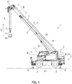
- crane 1 will be described.
- Crane 1 is mainly composed of traveling body 2 and swivel body 3.
- Traveling body 2 includes a pair of left and right front wheels 4 and rear wheels 5.
- traveling body 2 is provided with outrigger 6 which is grounded to stabilize when carrying load W.
- traveling body 2 supports pivot body 3, which is swivelable by the driving device, on the upper portion thereof.
- Swivel body 3 is provided with boom 7 so as to protrude forward from the rear portion of swivel body 3. Therefore, boom 7 is swivelable by the driving device (see arrow A). Further, boom 7 is extendible and retractable by the driving device (see arrow B). Further, boom 7 is luffing-free by the driving device (see arrow C). In addition, wire rope 8 is stretched over boom 7. On the proximal end side of boom 7, winch 9 around which wire rope 8 is wrapped is disposed, on the distal end side of boom 7, hook 10 is suspended by wire rope 8. Winch 9 is integrally configured with the driving device to allow winding and unwinding of wire rope 8. Therefore, the hook 10 is movable up and down by the driving device (see arrow D).
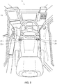
- swivel body 3 is provided with cabin 11 on the side of boom 7. Inside of cabin 11, swivel manipulation tool 21, extension/retraction manipulation tool 22, luffing manipulation tool 23, winding manipulation tool 24, to be described later, is provided. Image display 43 described later is also provided.
- operation system 12 will be described with reference to FIGS. 3 and 4 .
- the present operation system is an example of a conceivable configuration, and is not limited thereto.
- an operator who performs an operation in crane 1 will be referred to as an "operator Oa,” and an operator who performs an operation without riding on crane 1 will be described as an “operator Ob.”
- Operation system 12 is mainly composed of control apparatus 20.
- Various manipulating tools 21 to 24 are connected to control apparatus 20.
- various valves 25 to 28 are connected to control apparatus 20.
- weight sensor 29 is connected to control apparatus 20. Weight sensor 29 can detect the weight of load W. Therefore, control apparatus 20 can recognize the weight of load W.
- boom 7 is swivelable by the driving device (see arrow A in FIG. 1 ).
- a driving device is defined as swivel hydraulic motor 31.
- Swivel hydraulic motor 31 is appropriately operated by swivel valve 25 which is a directional control valve.
- swivel hydraulic motor 31 is appropriately operated by switching the flow direction of the hydraulic oil with swivel valve 25.
- Swivel valve 25 is operated based on the operation of swivel manipulation tool 21 by operator Oa.
- the swivel angle and the swivel speed of boom 7 is detected by a sensor which is not shown. Therefore, control apparatus 20 can recognize the swivel angle and the swivel speed of boom 7.
- boom 7 is extendible and retractable by the driving device (see arrow B in FIG).
- a driving device is defined as extension/retraction hydraulic cylinder 32.
- Extension/retraction hydraulic cylinder 32 is appropriately operated by extension/retraction valve 26 which is a directional control valve.
- extension/retraction hydraulic cylinder 32 is appropriately operated by switching the flow direction of the hydraulic oil with extension/retraction valve 26.
- Extension/retraction valve 26 is operated based on the operation of extension/retraction manipulation tool 22 by operator Oa. Further, the extension/retraction length and the extension/retraction speed of boom 7 are detected by a sensor which is not shown. Therefore, control apparatus 20 can recognize the extension/retraction length and the extension/retraction speed of boom 7.
- boom 7 is luffing-free by the driving device (see arrow C in FIG. 1 ).
- a driving device is defined as a luffing hydraulic cylinder 33.
- Luffing hydraulic cylinder 33 is appropriately operated by luffing valve 27 which is a directional control valve.
- luffing hydraulic cylinder 33 is appropriately operated by switching the flow direction of the hydraulic oil with luffing valve 27.
- Luffing valve 27 is operated based on the operation of luffing manipulation tool 23 by operator Oa.
- the luffing angle and the luffing speed of boom 7 is detected by a sensor which is not shown. Therefore, control apparatus 20 can recognize the luffing angle and the luffing speed of boom 7.
- hook 10 is movable up and down by the driving device (see arrow D in FIG).
- a drive device is defined as winding hydraulic motor 34.
- Winding hydraulic motor 34 is appropriately operated by winding valve 28 which is a directional control valve.
- winding hydraulic motor 34 is appropriately operated by switching the flow direction of the hydraulic oil or adjusting the flow rate of the hydraulic oil with winding valve 28.
- Winding valve 28 is operated based on the operation of winding manipulation tool 24 by operator Oa.
- slinging length L (see FIG. 1 ) and the ascending/descending speed of hook 10 is detected by a sensor which is not shown. Therefore, control apparatus 20 can recognize slinging length L and the ascending/descending speed of hook 10.
- operating system 12 includes camera 41, information relay device 42, and image display 43.
- information relay device 42 is unnecessary in a case where remote operating terminal 13 is of a wired type.
- Camera 41 is for taking an image.
- the camera 41 is attached to the distal end portion of boom 7 in order to take an image of hook 10 or load W suspended on hook 10 from above (see FIG. 1 ).
- Camera 41 is connected to information relay device 42.
- Information relay device 42 transmits and receives information converted into a radio wave signal.
- Information relay device 42 has at least an antenna attached to the distal end portion of boom 7 in order to reduce the influence on the radio waves due to grounded objects or the like.
- Information relay device 42 in addition to control apparatus 20, is connected to control apparatus 60 of remote operating terminal 13 to be described later. Therefore, information relay device 42 can transmit information from control apparatus 20 to control apparatus 60.
- Information relay device 42 may also transmit information from control apparatus 60 to control apparatus 20. Further, the image taken by camera 51 can be transmitted to control apparatus 20 and control apparatus 60.
- Image display 43 displays various images.
- Image display 43 is attached to the front side of cabin 11 so that operator Oa can visually recognize the image while manipulating various manipulation tools 21 to 24.
- Image display 43 is connected to control apparatus 20. Therefore, control apparatus 20 can provide information to operator Oa via image display 43.
- operating system 12 includes remote operating terminal 13.
- Remote operating terminal 13 is provided with control apparatus 60. Further, remote operating terminal 13 includes a transmitter and a receiver which are not shown. Remote operating terminal 13 in the present application is an example of a remote operating terminal, and is not limited thereto.
- Remote operating terminal 13 is provided with swivel manipulation tool 61.
- Swivel manipulation tool 61 is connected to control apparatus 60. Then, control apparatus 60 is connected to control apparatus 20 described above via a radio wave signal. Therefore, when operator Ob tilts swivel manipulation tool 61 in a direction (see arrow E in FIG. 4 ), the swivel motion of boom 7 is performed in the same manner as the swivel manipulation tool 21 is tilted in a direction described above. That is, when operator Ob tilts swivel manipulation tool 61 in a direction, swivel hydraulic motor 31 is appropriately operated, so that boom 7 is swiveled in the right or left direction.
- Remote operating terminal 13 is provided with extension/retraction manipulation tool 62.
- Extension/retraction manipulation tool 62 is connected to control apparatus 60. Then, control apparatus 60 is connected to control apparatus 20 described above via a radio wave signal. Therefore, when operator Ob tilts extension/retraction manipulation tool 62 in a direction (see arrow F in FIG. 4 ), the extension/retraction operation of boom 7 is performed in the same manner as extension/retraction manipulation tool 22 is tilted in a direction described above. That is, when operator Ob tilts extension/retraction manipulation tool 62 in a direction, extension/retraction hydraulic cylinder 32 is appropriately operated, so that boom 7 is extended or retracted.
- remote operating terminal 13 is provided with luffing manipulation tool 63.
- Luffing manipulation tool 63 is connected to control apparatus 60. Then, control apparatus 60 is connected to control apparatus 20 described above via a radio wave signal. Therefore, when operator Ob tilts luffing manipulation tool 63 in a direction (see arrow G in FIG. 4 ), the luffing operation of boom 7 is performed in the same manner as luffing manipulation tool 23 is tilted in a direction described above. That is, when the operator Ob tilts the luffing operation tool 63 in any direction, the luffing hydraulic cylinder 33 is appropriately operated, so that boom 7 is luffed up or down.
- remote operating terminal 13 is provided with winding manipulation tool 64.
- Winding manipulation tool 64 is connected to control apparatus 60.
- control apparatus 60 is connected to control apparatus 20 described above via a radio wave signal. Therefore, when operator Ob tilts winding manipulation tool 64 in a direction (see arrow H in FIG. 4 ), the ascending/descending motion of hook 10 is performed in the same manner as winding manipulation tool 24 is tilted in a direction described above. That is, when operator Ob tilts winding manipulation tool 64 in a direction, winding hydraulic motor 34 is appropriately operated, so that hook 10 is moved up or down.
- remote operating terminal 13 is provided with an image display 65.
- Image display 65 is connected to control apparatus 60. Then, control apparatus 60 is connected to control apparatus 20 via a radio wave signal described above. Therefore, control apparatus 20 can provide information to operator Ob via image display 65.
- image display 65 is a so-called touch panel, it can be the input device of operator Ob. Therefore, operator Ob can also provide information to control apparatus 20 via image display 65.
- Image display 65 is attached to the front surface of remote operating terminal 13 so that operator Ob can visually recognize the image while manipulating the various manipulation tools 61 to 64.
- control apparatus 20 includes basic control signal generation section 20a, resonance frequency computation section 20b, filter coefficient computation section 20c, and filtered control signal generation section 20d.
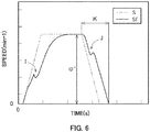
- the basic control signal generation section 20a generates basic control signal S which is a speed command of each driving device (31 to 34) (see Fig. 6 ).
- the basic control signal generation section 20a recognizes the manipulated amount and the manipulated speed of various manipulation tools 21 to 24, 61 to 64 by the operator, and generates basic control signal S for each situation.
- basic control signal generation section 20a generates basic control signal S corresponding to the manipulated amount and the manipulated speed of swivel manipulation tool 21, 61, basic control signal S corresponding to the manipulated amount and the manipulated speed of extension/retraction manipulation tool 22, 62, basic control signal S corresponding to the manipulated amount and the manipulated speed of luffing manipulation tool 23, 63, and basic control signal S corresponding to the manipulated amount and the manipulated speed of winding manipulation tool 24, 64.
- Resonance frequency computation section 20b computes resonance frequency co which is the frequency of the swing of load W caused by the operation of each driving device (31 to 34).
- Resonance frequency computation section 20b recognizes slinging length L of hook 10 based on the posture of boom 7 and the unwinding amount of wire rope 8, and calculates resonance frequency co for each situation.
- Filtered control signal generation section 20d along with generating notch filter F, is intended to generate filtered control signal Sf by applying notch filter F to basic control signal S (see FIG. 6 ).
- Filtered control signal generation section 20d acquires various coefficients ⁇ n , ⁇ , ⁇ from filter coefficient computation section 20c to generate notched filter F.
- filtered control signal generation section 20d acquires basic control signal S from basic control signal generation section 20a to generate filtered control signal Sf by applying notch filter F to basic control signal S.
- filtered control signal generation section 20d generates filtered control signal Sf from basic control signal S and notch filter F corresponding to the manipulated amount or the like of swivel manipulation tool 21, 61, filtered control signal Sf from basic control signal S and notch filter F corresponding to the manipulated amount or the like of extension/retraction manipulation tool 22, 62, filtered control signal Sf from basic control signal S and notch filter F corresponding to the manipulated amount or the like of luffing manipulation tool 23, 63, and filtered control signal Sf from basic control signal S and notch filter F corresponding to the manipulated amount or the like of winding manipulation tool 24, 64.
- control apparatus 20 can control various valves 25-28 based on filtered control signal Sf.
- each driving device (31-34) can be controlled based on filtered control signal Sf.
- Notch filter F has a characteristic in which the attenuation rate becomes higher as it approaches resonance frequency co in any range centered on resonance frequency ⁇ .
- Any range centered on resonant frequency co is represented as notch width Bn
- the difference in the attenuation amount in notch width Bn is represented as notch depth Dn. Therefore, notch filter F is specified by resonance frequency co, notch width Bn and notch depth Dn.
- Filtered control signal Sf is a speed command transmitted to each driving device (31-34).
- Filtered control signal Sf according to the acceleration of boom 7 has a characteristic in which the acceleration of filtered control signal Sf is milder than that of basic control signal S, and it accelerates again after temporarily decelerating (see part I in Fig. 6 ).
- the reason why the deceleration is temporarily performed is to suppress the swing of load W at the time of acceleration.
- filtered control signal Sf according to the deceleration of boom 7 has a characteristic in which the deceleration of filtered control signal Sf is milder or comparable than that of basic control signal S, and it decelerates again after temporarily accelerating (see section J in FIG. 6 ).
- control apparatus 20 can calculate time K which is the time until the speed command becomes 0 after operator Oa, Ob performs the stop operation. Therefore, control apparatus 20 can predict the braking distance of boom 7 by utilizing time K, the speed transition, resonance frequency co, and the like. However, it is also possible to predict the braking distance by other mathematical methods without utilizing time K.
- Control apparatus 20 can recognize the position of remote operating terminal 13. This can be realized by the antenna of information relay device 42 having a directivity characteristic. Further, as described above, control apparatus 20 can recognize the swivel angle, the extension/retraction length, and the luffing angle of boom 7. Therefore, the control apparatus 20 can recognize the positional direction of the remote operating terminal 13 with respect to camera 41. Accordingly, control apparatus 20 can recognize angle ⁇ formed by the supporting direction of camera 41 by boom 7 and the positional direction of remote operating terminal 13 with respect to camera 41 (see FIG. 8 ). It should be noted that "the supporting direction of camera 41 by boom 7" is a direction along virtual line V1 (see FIG. 8 ) connecting swivel center M and camera 41 of boom 7 when viewed from above.
- control apparatus 20 is connected to an azimuth meter which is not shown, and can recognize the azimuth.
- the azimuth in the present application is represented by an azimuth symbol in FIG. 8 .
- boom 7 swivels in response to the manipulation of swivel manipulation tool 21 by operator Oa or the manipulation of swivel manipulation tool 61 by operator Ob.
- camera 41 swivels with boom 7.
- aim point P of camera 41 will also swivel with boom 7 (see arrow N in FIG. 7 ), thus image area R1, R2 centered on aim point P will also swivel.
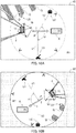
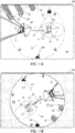
- Image region R1 is displayed on image display 43 provided inside cabin 11 (see FIG. 9A ).
- Image region R1 has a rectangular shape inscribed in the photographing range of camera 41. This is intended to provide a broad view of the surrounding condition of hook 10 or load W suspended on hook 10.
- Image region R2 is displayed on image display 65 provided on the upper surface of remote operating terminal 13 (see FIG. 9B ).
- Image region R2 has a circular shape inscribed in image region R1. This takes into consideration the fact that operator Ob can recognize that the image is turned and displayed, in addition to the fact that the image is not lost (no partially missing part of the image) even if the image is turned.
- the image is turned based on angle ⁇ . This is because directions are most easily recognized in the image by operator Ob.
- the moving direction of hook 10 or load W suspended on hook 10 is displayed by arrow-type image T (see FIG. 9A and 9B ).
- arrow-type image T Considering that hook 10 or load W suspended on hook 10 is vertically downward at the distal end portion of boom 7, it can be said that such a moving direction is equal to the direction in which the distal end portion of boom 7 moves.
- the length of image T is appropriately adjusted in accordance with the moving speed.
- the color of image T may be changed in accordance with the acceleration/deceleration. Further, the mode of flashing image T or the like may be changed in accordance with the acceleration/deceleration.
- marker U1 indicating the positional direction of traveling body 2 is displayed in image region R1, R2.
- Marker U2 indicating the positional direction of remote operating terminal 13 is displayed in image region R1, R2.
- marker U3 indicating the azimuth is displayed in image region R1, R2.
- the braking distance of boom 7 when operator Oa, Ob performs the swivel stop operation is calculated as follows.
- the braking distance of boom 7 will be described as ⁇ ⁇ .
- Braking distance ⁇ ⁇ of boom 7 is expressed by the following equation.
- ⁇ is the swivel speed of boom 7
- T is the load swing period.
- Pnf is the load swing reduction rate
- Dcc is the deceleration limit. It should be noted that swivel speed ⁇ ' of boom 7 is detected by the sensor (see FIG. 6 ). Load swing period T, load swing reduction rate Pnf and deceleration limit Dcc will be described later.
- ⁇ ⁇ ⁇ ′ T Pnf + ⁇ ′ 2 / 2 Dcc
- Load swing period T can be expressed using resonant frequency ⁇ . Therefore, load swing period T is expressed by the following equation.
- Load swing reduction rate Pnf is a value determined by a function using notch width coefficient ⁇ and notch depth coefficient ⁇ .
- the deceleration limit Dcc is a limit value when reducing the rotational speed of swivel hydraulic motor 31.
- the swing amount of load W is calculated by the following equation.
- the swing amount (amplitude) of load W will be described as ⁇ ⁇ .
- hook 10 and load W are regarded as a single rigid body, and then, the restoring force thereof is defined as F and the weight thereof is defined as M.
- the restoring force of hook 10 is F and the weight of hook 10 is M.
- the braking distance of boom 7 is displayed in image region R1, R2. More specifically, since arrow-type image T extends in image region R1, R2, the braking distance of boom 7 is displayed on the extension line of image T. Considering that hook 10 or load W suspended on hook 10 is vertically downward at the distal end portion of boom 7, it can be said that the braking distance of boom 7 is equal to the braking distance of hook 10 or load W suspended on hook 10. Note that the value of the braking distance changes continuously in relation to the speed transition and the time transition. In the present application, the situation in which boom 7 swivels has been described, but the present invention is also applicable to a situation in which boom 7 extends or retracts and luffs up or down. Further, in addition to the swivel or the like of boom 7, it is also applicable to a situation where hook 10 ascends or descends.
- crane 1 includes the driving devices (31 to 34) for performing the operation of boom 7, control apparatus 20 for controlling the operating state of the driving devices (31 to 34), camera 41 for taking an image downward from the distal end portion of boom 7, and image display 43, 65 for displaying the image taken by camera 41. Then, in the case where the motion of boom 7 is stopped, control apparatus 20 generates filtered control signal Sf by applying filter F to basic control signal S of driving device (31 to 34), and controls drive device 20 based on filtered control signal Sf, and predicts the braking distance of boom 7 to display on image display 43, 65.
- marker Y of load W may be displayed at such a position.
- Marker Y is obtained by cutting out the image of load W taken by camera 41, but is not limited thereto. For example, it may be a simple figure such as a circle or a rectangle.
- control apparatus 20 predicts the position at which load W stops, and displays marker Y of load W on image display 43, 65. According to such crane 1, it is possible to easily determine whether load W collides with a building or the like from displayed marker Y of load W. Therefore, it is possible to perform the avoidance operation before load W collides with a building or the like.
- Swing range Yr of load W in consideration of such a swing amount may be displayed.
- Swing range Yr has a large elliptical shape in the moving direction of load W (elliptical shape having the long axis along the moving direction of load W), but is not limited thereto. For example, it may be a straight line indicating a range or the like.
- control apparatus 20 predicts the swing amount of load W and displays the swing range Yr of load W on image display 43, 65. According to such crane 1, it is possible to easily determine whether load W collides with a building or the like from displayed swing range Yr of load W. Therefore, it is possible to perform the avoidance operation before load W collides with a building or the like.
- marker Z of hook 10 may be displayed at such a position.
- Marker Z is obtained by cutting out the image of hook 10 taken by camera 41, but is not limited thereto. For example, it may be a simple figure such as a circle or a rectangle.
- control apparatus 20 predicts the position at which hook 10 stops, and displays marker Z of hook 10 on image display 43, 65. According to such crane 1, it is possible to easily determine whether hook 10 collides with a building or the like from displayed marker Z. Therefore, it is possible to perform an avoidance operation before hook 10 collides with a building or the like.
- Swing range Zr of hook 10 since the present crane 1 can predict the swing amount (amplitude) of hook 10 from deceleration of boom 7 or slinging length L of hook 10, swing range Zr of hook 10 in consideration of such a swing amount may be displayed.
- Swing range Zr has a large elliptical shape in the moving direction of hook 10 (elliptical shape having the long axis along the moving direction of hook 10), but is not limited thereto. For example, it may be a straight line indicating a range or the like.
- control apparatus 20 predicts the swing amount of hook 10 and displays the swing range Zr of hook 10 on image display 43, 65. According to such a crane 1, it is possible to easily determine whether hook 10 collide with the building or the like from displayed swing range Zr of hook 10. Therefore, it is possible to perform an avoidance operation before hook 10 collides with a building or the like.
- notch filter F as a filter for generating filtered control signal Sf
- the band-stop filter which can attenuate or reduce by a specific frequency range is sufficient.
- it is a band limit filter, a band elimination filter, or the like.
- the present invention can be utilized for cranes.
Landscapes
- Engineering & Computer Science (AREA)
- Mechanical Engineering (AREA)
- Automation & Control Theory (AREA)
- Control And Safety Of Cranes (AREA)
- Jib Cranes (AREA)
Abstract
Description
- The present invention relates to cranes. The present invention particularly relates to a crane capable of grasping the surrounding conditions of a hook or a load suspended on a hook and at the same time grasping the braking distance at the time of stopping operation.
- Conventionally, cranes are known to be typical working vehicles. The crane is mainly composed of a traveling body and a swivel body. The traveling body is provided with a plurality of wheels and is configured to travel freely. The swivel body is provided with a wire rope and a hook in addition to a boom, and is configured to carry a load freely. In such a crane, a driving device for performing the operation of the boom, and a control apparatus for controlling the operating state of the driving device are provided.
- A crane has been proposed in which the control apparatus creates a filtered control signal and the driving device is controlled based on the filtered control signal (see Patent Literature 1). Here, the filtered control signal is obtained by applying a filter having a predetermined characteristic to the basic control signal of the driving device. For example, the notch filter has a characteristic that the attenuation rate becomes higher as it approaches the resonance frequency in any range centered on the resonance frequency.
- Here, it is assumed that the operation of stopping the swivel motion of the boom is performed and the hook or the load suspended on the hook is stopped. In this case, even if the operator performs the operation of stopping the swivel motion of the boom, the boom continues the swivel motion while decelerating for a while. Instead of immediately stopping the swivel motion of the boom, this is intended to suppress the swing of the load by providing a deceleration period based on the filtered control signal. However, a longer braking distance of the boom increases the possibility that the hook or the load suspended on a hook will collide with a building or the like. Therefore, the crane capable of grasping the surrounding conditions of the hook or the load suspended on the hook and at the same time grasping the braking distance at the time of stopping operation was required.
- Japanese Patent Application Laid-Open No.
2015-151211 - This application relates to the crane capable of grasping the surrounding conditions of the hook or the load suspended on the hook and at the same time grasping the braking distance at the time of stopping operation.
- The present invention is a crane comprising:
- a boom;
- a wire rope hanging from the boom; and
- a hook ascending and descending by winding and unwinding of the wire rope;
- a driving device for performing a motion of the boom;
- a control apparatus for controlling an operating state of the driving device;
- a camera for taking an image downward from a distal end portion of the boom; and
- an image display for displaying the image taken by the camera;
- In the present invention, the control apparatus predicts a position at which the load stops and displays a marker of the load on the image display.
- In the present invention, the control apparatus predicts a swing amount of the load and displays a swing range of the load on the image display.
- In the present invention, the control apparatus predicts a position at which the hook stops and displays a marker of the hook on the image display.
- In the present invention, the control apparatus predicts a swing amount of the hook and displays a swing range of the hook on the image display.
- According to the crane of the present invention, a driving device for performing a motion of the boom, a control apparatus for controlling an operating state of the driving device, a camera for taking an image downward from a distal end portion of the boom and an image display for displaying the image taken by the camera are provided. In a case where the motion of the boom is stopped, the control apparatus generates a filtered control signal by applying a filter to a basic control signal of the driving device and controls the driving device based on the filtered control signal, and predicts a braking distance of the boom to display the braking distance thereof on the image display. According to such a crane, an operator can grasp the surrounding condition of the hook or the load suspended on the hook by viewing the image display, and at the same time, can grasp the braking distance of the boom. It is thus possible to perform an avoidance operation before the hook or the load suspended on a hook collides with a building or the like.
- According to the crane of the present invention, the control apparatus predicts the position at which the load stops and displays the marker of the load on the image display. According to such a crane, it is possible to easily determine whether the load collides with a building or the like from the displayed marker of the load. Therefore, it is possible to perform the avoidance operation before the load collides with a building or the like.
- According to the crane of the present invention, the control apparatus predicts a swing amount of the load and displays a swing range of the load on the image display. According to such a crane, it is possible to easily determine whether the load collides with a building or the like from the displayed swing range of the load. Therefore, it is possible to perform the avoidance operation before the load collides with a building or the like.
- According to the crane of the present invention, the control apparatus predicts a position at which the hook stops and displays a marker of the hook on the image display. According to such a crane, it is possible to easily determine whether the hook collides with a building or the like from the displayed marker of the hook. Therefore, it is possible to perform the avoidance operation before the hook collides with a building or the like.
- According to the crane of the present invention, the control apparatus predicts a swing amount of the hook and displays a swing range of the hook on the image display. According to such a crane, it is possible to easily determine whether the hook collide with a building or the like from the displayed swing range of the hook. Therefore, it is possible to perform the avoidance operation before the hook collides with a building or the like.
-
-
FIG. 1 illustrates a crane; -
FIG. 2 illustrates an inside of a cabin; -
FIG. 3 illustrates a configuration of an operation system; -
FIG. 4 illustrates a remote operating terminal; -
FIG. 5 illustrates a graph indicating frequency characteristics of the notch filter; -
FIG. 6 illustrates a basic control signal and a filtered control signal; -
FIG. 7 illustrates a swivel motion of a boom; -
FIG. 8 illustrates a situation in which the boom is swiveling; -
FIG. 9 illustrates a display aspect of a situation in which the boom is swiveling; -
FIG. 10 illustrates a display aspect of a situation in which an operator performs a swivel stop operation; -
FIG. 11 illustrates a display aspect of a situation in which an operator performs a swivel stop operation; and -
FIG. 12 illustrates a display aspect of a situation in which an operator performs a swivel stop operation. - The technical idea disclosed in the present application can be applied to other cranes as well as
crane 1 described below. - First, with reference to
FIGS. 1 and2 ,crane 1 will be described. -
Crane 1 is mainly composed of travelingbody 2 and swivelbody 3. - Traveling
body 2 includes a pair of left and rightfront wheels 4 andrear wheels 5. In addition, travelingbody 2 is provided withoutrigger 6 which is grounded to stabilize when carrying load W. It should be noted that travelingbody 2 supportspivot body 3, which is swivelable by the driving device, on the upper portion thereof. -
Swivel body 3 is provided withboom 7 so as to protrude forward from the rear portion ofswivel body 3. Therefore,boom 7 is swivelable by the driving device (see arrow A). Further,boom 7 is extendible and retractable by the driving device (see arrow B). Further,boom 7 is luffing-free by the driving device (see arrow C). In addition,wire rope 8 is stretched overboom 7. On the proximal end side ofboom 7,winch 9 around whichwire rope 8 is wrapped is disposed, on the distal end side ofboom 7,hook 10 is suspended bywire rope 8.Winch 9 is integrally configured with the driving device to allow winding and unwinding ofwire rope 8. Therefore, thehook 10 is movable up and down by the driving device (see arrow D). It should be noted thatswivel body 3 is provided withcabin 11 on the side ofboom 7. Inside ofcabin 11,swivel manipulation tool 21, extension/retraction manipulation tool 22, luffingmanipulation tool 23, windingmanipulation tool 24, to be described later, is provided.Image display 43 described later is also provided. - Next,
operation system 12 will be described with reference toFIGS. 3 and4 . However, the present operation system is an example of a conceivable configuration, and is not limited thereto. Hereinafter, an operator who performs an operation incrane 1 will be referred to as an "operator Oa," and an operator who performs an operation without riding oncrane 1 will be described as an "operator Ob." -
Operation system 12 is mainly composed ofcontrol apparatus 20. Various manipulatingtools 21 to 24 are connected to controlapparatus 20. Further,various valves 25 to 28 are connected to controlapparatus 20. In addition,weight sensor 29 is connected to controlapparatus 20.Weight sensor 29 can detect the weight of load W. Therefore,control apparatus 20 can recognize the weight of load W. - As described above,
boom 7 is swivelable by the driving device (see arrow A inFIG. 1 ). In the present application, such a driving device is defined as swivelhydraulic motor 31. Swivelhydraulic motor 31 is appropriately operated byswivel valve 25 which is a directional control valve. In other words, swivelhydraulic motor 31 is appropriately operated by switching the flow direction of the hydraulic oil withswivel valve 25.Swivel valve 25 is operated based on the operation ofswivel manipulation tool 21 by operator Oa. Further, the swivel angle and the swivel speed ofboom 7 is detected by a sensor which is not shown. Therefore,control apparatus 20 can recognize the swivel angle and the swivel speed ofboom 7. - Further, as described above,
boom 7 is extendible and retractable by the driving device (see arrow B in FIG). In the present application, such a driving device is defined as extension/retractionhydraulic cylinder 32. Extension/retractionhydraulic cylinder 32 is appropriately operated by extension/retraction valve 26 which is a directional control valve. In other words, extension/retractionhydraulic cylinder 32 is appropriately operated by switching the flow direction of the hydraulic oil with extension/retraction valve 26. Extension/retraction valve 26 is operated based on the operation of extension/retraction manipulation tool 22 by operator Oa. Further, the extension/retraction length and the extension/retraction speed ofboom 7 are detected by a sensor which is not shown. Therefore,control apparatus 20 can recognize the extension/retraction length and the extension/retraction speed ofboom 7. - Further, as described above,
boom 7 is luffing-free by the driving device (see arrow C inFIG. 1 ). In the present application, such a driving device is defined as a luffinghydraulic cylinder 33. Luffinghydraulic cylinder 33 is appropriately operated by luffingvalve 27 which is a directional control valve. In other words, luffinghydraulic cylinder 33 is appropriately operated by switching the flow direction of the hydraulic oil with luffingvalve 27. Luffingvalve 27 is operated based on the operation of luffingmanipulation tool 23 by operator Oa. Further, the luffing angle and the luffing speed ofboom 7 is detected by a sensor which is not shown. Therefore,control apparatus 20 can recognize the luffing angle and the luffing speed ofboom 7. - In addition, as described above,
hook 10 is movable up and down by the driving device (see arrow D in FIG). In the present application, such a drive device is defined as windinghydraulic motor 34. Windinghydraulic motor 34 is appropriately operated by windingvalve 28 which is a directional control valve. In other words, windinghydraulic motor 34 is appropriately operated by switching the flow direction of the hydraulic oil or adjusting the flow rate of the hydraulic oil with windingvalve 28. Windingvalve 28 is operated based on the operation of windingmanipulation tool 24 by operator Oa. Further, slinging length L (seeFIG. 1 ) and the ascending/descending speed ofhook 10 is detected by a sensor which is not shown. Therefore,control apparatus 20 can recognize slinging length L and the ascending/descending speed ofhook 10. - In addition,
operating system 12 includescamera 41,information relay device 42, andimage display 43. However,information relay device 42 is unnecessary in a case whereremote operating terminal 13 is of a wired type. -
Camera 41 is for taking an image. Thecamera 41 is attached to the distal end portion ofboom 7 in order to take an image ofhook 10 or load W suspended onhook 10 from above (seeFIG. 1 ).Camera 41 is connected toinformation relay device 42. -
Information relay device 42 transmits and receives information converted into a radio wave signal.Information relay device 42 has at least an antenna attached to the distal end portion ofboom 7 in order to reduce the influence on the radio waves due to grounded objects or the like.Information relay device 42, in addition tocontrol apparatus 20, is connected to controlapparatus 60 ofremote operating terminal 13 to be described later. Therefore,information relay device 42 can transmit information fromcontrol apparatus 20 to controlapparatus 60.Information relay device 42 may also transmit information fromcontrol apparatus 60 to controlapparatus 20. Further, the image taken by camera 51 can be transmitted to controlapparatus 20 andcontrol apparatus 60. -
Image display 43 displays various images.Image display 43 is attached to the front side ofcabin 11 so that operator Oa can visually recognize the image while manipulatingvarious manipulation tools 21 to 24.Image display 43 is connected to controlapparatus 20. Therefore,control apparatus 20 can provide information to operator Oa viaimage display 43. - In addition,
operating system 12 includesremote operating terminal 13.Remote operating terminal 13 is provided withcontrol apparatus 60. Further,remote operating terminal 13 includes a transmitter and a receiver which are not shown.Remote operating terminal 13 in the present application is an example of a remote operating terminal, and is not limited thereto. -
Remote operating terminal 13 is provided withswivel manipulation tool 61.Swivel manipulation tool 61 is connected to controlapparatus 60. Then,control apparatus 60 is connected to controlapparatus 20 described above via a radio wave signal. Therefore, when operator Ob tilts swivelmanipulation tool 61 in a direction (see arrow E inFIG. 4 ), the swivel motion ofboom 7 is performed in the same manner as theswivel manipulation tool 21 is tilted in a direction described above. That is, when operator Ob tilts swivelmanipulation tool 61 in a direction, swivelhydraulic motor 31 is appropriately operated, so thatboom 7 is swiveled in the right or left direction. -
Remote operating terminal 13 is provided with extension/retraction manipulation tool 62. Extension/retraction manipulation tool 62 is connected to controlapparatus 60. Then,control apparatus 60 is connected to controlapparatus 20 described above via a radio wave signal. Therefore, when operator Ob tilts extension/retraction manipulation tool 62 in a direction (see arrow F inFIG. 4 ), the extension/retraction operation ofboom 7 is performed in the same manner as extension/retraction manipulation tool 22 is tilted in a direction described above. That is, when operator Ob tilts extension/retraction manipulation tool 62 in a direction, extension/retractionhydraulic cylinder 32 is appropriately operated, so thatboom 7 is extended or retracted. - Further,
remote operating terminal 13 is provided with luffingmanipulation tool 63.Luffing manipulation tool 63 is connected to controlapparatus 60. Then,control apparatus 60 is connected to controlapparatus 20 described above via a radio wave signal. Therefore, when operator Ob tilts luffingmanipulation tool 63 in a direction (see arrow G inFIG. 4 ), the luffing operation ofboom 7 is performed in the same manner as luffingmanipulation tool 23 is tilted in a direction described above. That is, when the operator Ob tilts the luffingoperation tool 63 in any direction, the luffinghydraulic cylinder 33 is appropriately operated, so thatboom 7 is luffed up or down. - In addition,
remote operating terminal 13 is provided with windingmanipulation tool 64. Windingmanipulation tool 64 is connected to controlapparatus 60. Then,control apparatus 60 is connected to controlapparatus 20 described above via a radio wave signal. Therefore, when operator Ob tilts windingmanipulation tool 64 in a direction (see arrow H inFIG. 4 ), the ascending/descending motion ofhook 10 is performed in the same manner as windingmanipulation tool 24 is tilted in a direction described above. That is, when operator Ob tilts windingmanipulation tool 64 in a direction, windinghydraulic motor 34 is appropriately operated, so thathook 10 is moved up or down. - In addition,
remote operating terminal 13 is provided with animage display 65.Image display 65 is connected to controlapparatus 60. Then,control apparatus 60 is connected to controlapparatus 20 via a radio wave signal described above. Therefore,control apparatus 20 can provide information to operator Ob viaimage display 65. On the other hand, sinceimage display 65 is a so-called touch panel, it can be the input device of operator Ob. Therefore, operator Ob can also provide information to controlapparatus 20 viaimage display 65.Image display 65 is attached to the front surface ofremote operating terminal 13 so that operator Ob can visually recognize the image while manipulating thevarious manipulation tools 61 to 64. - Thus,
remote operating terminal 13 can operate each driving device (31-34) viacontrol apparatus 20. It should be noted thatcontrol apparatus 20 includes basic controlsignal generation section 20a, resonancefrequency computation section 20b, filtercoefficient computation section 20c, and filtered controlsignal generation section 20d. - The basic control
signal generation section 20a generates basic control signal S which is a speed command of each driving device (31 to 34) (seeFig. 6 ). The basic controlsignal generation section 20a recognizes the manipulated amount and the manipulated speed ofvarious manipulation tools 21 to 24, 61 to 64 by the operator, and generates basic control signal S for each situation. Specifically, basic controlsignal generation section 20a generates basic control signal S corresponding to the manipulated amount and the manipulated speed ofswivel manipulation tool retraction manipulation tool manipulation tool manipulation tool - Resonance
frequency computation section 20b computes resonance frequency co which is the frequency of the swing of load W caused by the operation of each driving device (31 to 34). Resonancefrequency computation section 20b recognizes slinging length L ofhook 10 based on the posture ofboom 7 and the unwinding amount ofwire rope 8, and calculates resonance frequency co for each situation. Specifically, resonancefrequency computation section 20b calculates resonance frequency co based on the following equation using slinging length L and gravity acceleration g ofhook 10.
- Filter
coefficient computation section 20c calculates notch width coefficient ζ and notch depth coefficient δ in addition to center frequency coefficient ωn of transfer coefficient H(s) of notch filter F, which will be described later. Filtercoefficient computation section 20c calculates corresponding center frequency coefficient ωn centered on resonance frequency co calculated by resonancefrequency computation section 20b. Further, filtercoefficient computation section 20c calculates notch width coefficient ζ and notch depth coefficient δ corresponding to respective basic control signal S. Transfer coefficient H(s) is expressed by the following equation using center frequency coefficient ωn, notch width coefficient ζ, and notch depth coefficient δ.
- Filtered control
signal generation section 20d, along with generating notch filter F, is intended to generate filtered control signal Sf by applying notch filter F to basic control signal S (seeFIG. 6 ). Filtered controlsignal generation section 20d acquires various coefficients ωn, ζ, δ from filtercoefficient computation section 20c to generate notched filter F. Further, filtered controlsignal generation section 20d acquires basic control signal S from basic controlsignal generation section 20a to generate filtered control signal Sf by applying notch filter F to basic control signal S. Specifically, filtered controlsignal generation section 20d generates filtered control signal Sf from basic control signal S and notch filter F corresponding to the manipulated amount or the like ofswivel manipulation tool retraction manipulation tool manipulation tool manipulation tool - With such a configuration,
control apparatus 20 can control various valves 25-28 based on filtered control signal Sf. Thus, each driving device (31-34) can be controlled based on filtered control signal Sf. - Next, with reference to
FIGS. 5 and6 , notch filter F and filtered control signal Sf will be described. - Notch filter F has a characteristic in which the attenuation rate becomes higher as it approaches resonance frequency co in any range centered on resonance frequency ω. Any range centered on resonant frequency co is represented as notch width Bn, the difference in the attenuation amount in notch width Bn is represented as notch depth Dn. Therefore, notch filter F is specified by resonance frequency co, notch width Bn and notch depth Dn. Notch depth Dn is intended to be determined based on notch depth coefficient δ. Therefore, in a case where notch depth factor δ = 0, the gain characteristic at resonant frequency co becomes -∞ dB, and in a case where notch depth factor δ = 1, the gain characteristic at the resonant frequency co becomes 0 dB.
- Filtered control signal Sf is a speed command transmitted to each driving device (31-34). Filtered control signal Sf according to the acceleration of
boom 7 has a characteristic in which the acceleration of filtered control signal Sf is milder than that of basic control signal S, and it accelerates again after temporarily decelerating (see part I inFig. 6 ). Here, the reason why the deceleration is temporarily performed is to suppress the swing of load W at the time of acceleration. Further, filtered control signal Sf according to the deceleration ofboom 7 has a characteristic in which the deceleration of filtered control signal Sf is milder or comparable than that of basic control signal S, and it decelerates again after temporarily accelerating (see section J inFIG. 6 ). Here, the reason why the acceleration is temporarily performed is to suppress the swing of load W at the time of deceleration. It should be noted thatcontrol apparatus 20 can calculate time K which is the time until the speed command becomes 0 after operator Oa, Ob performs the stop operation. Therefore,control apparatus 20 can predict the braking distance ofboom 7 by utilizing time K, the speed transition, resonance frequency co, and the like. However, it is also possible to predict the braking distance by other mathematical methods without utilizing time K. - Next, with reference to
FIGS. 7 to 9 , a display mode ofimage display boom 7 is swiveling. - First, the premise in the present application will be briefly described.
-
Control apparatus 20 can recognize the position ofremote operating terminal 13. This can be realized by the antenna ofinformation relay device 42 having a directivity characteristic. Further, as described above,control apparatus 20 can recognize the swivel angle, the extension/retraction length, and the luffing angle ofboom 7. Therefore, thecontrol apparatus 20 can recognize the positional direction of theremote operating terminal 13 with respect tocamera 41. Accordingly,control apparatus 20 can recognize angle α formed by the supporting direction ofcamera 41 byboom 7 and the positional direction ofremote operating terminal 13 with respect to camera 41 (seeFIG. 8 ). It should be noted that "the supporting direction ofcamera 41 byboom 7" is a direction along virtual line V1 (seeFIG. 8 ) connecting swivel center M andcamera 41 ofboom 7 when viewed from above. Further, "the positional direction ofremote operating terminal 13 with respect tocamera 41" is a direction along virtual line V2 (seeFIG. 8 ) connectingcamera 41 andremote operating terminal 13 when viewed from above. In addition,control apparatus 20 is connected to an azimuth meter which is not shown, and can recognize the azimuth. The azimuth in the present application is represented by an azimuth symbol inFIG. 8 . - As described above,
boom 7 swivels in response to the manipulation ofswivel manipulation tool 21 by operator Oa or the manipulation ofswivel manipulation tool 61 by operator Ob. At this time,camera 41 swivels withboom 7. Then, aim point P ofcamera 41 will also swivel with boom 7 (see arrow N inFIG. 7 ), thus image area R1, R2 centered on aim point P will also swivel. - In the situation where
boom 7 is swiveling, it is assumed that load Q placed on the ground is included inside image region R1 (seeFIG. 8 ). Image region R1 is displayed onimage display 43 provided inside cabin 11 (seeFIG. 9A ). Image region R1 has a rectangular shape inscribed in the photographing range ofcamera 41. This is intended to provide a broad view of the surrounding condition ofhook 10 or load W suspended onhook 10. - At the same time, in the situation where
boom 7 is swiveling, it is assumed that load Q placed on the ground is also included inside image region R2 (seeFIG. 8 ). Image region R2 is displayed onimage display 65 provided on the upper surface of remote operating terminal 13 (seeFIG. 9B ). Image region R2 has a circular shape inscribed in image region R1. This takes into consideration the fact that operator Ob can recognize that the image is turned and displayed, in addition to the fact that the image is not lost (no partially missing part of the image) even if the image is turned. The image is turned based on angle α. This is because directions are most easily recognized in the image by operator Ob. - In addition, in image region R1 and R2, the moving direction of
hook 10 or load W suspended onhook 10 is displayed by arrow-type image T (seeFIG. 9A and 9B ). Considering thathook 10 or load W suspended onhook 10 is vertically downward at the distal end portion ofboom 7, it can be said that such a moving direction is equal to the direction in which the distal end portion ofboom 7 moves. The length of image T is appropriately adjusted in accordance with the moving speed. The color of image T may be changed in accordance with the acceleration/deceleration. Further, the mode of flashing image T or the like may be changed in accordance with the acceleration/deceleration. - In addition, marker U1 indicating the positional direction of traveling
body 2 is displayed in image region R1, R2. Marker U2 indicating the positional direction ofremote operating terminal 13 is displayed in image region R1, R2. Further, marker U3 indicating the azimuth is displayed in image region R1, R2. - The braking distance of
boom 7 when operator Oa, Ob performs the swivel stop operation is calculated as follows. Here, the braking distance ofboom 7 will be described as Δ Φ. - Braking distance Δ Φ of
boom 7 is expressed by the following equation. At this time, "Φ" is the swivel speed ofboom 7, and "T" is the load swing period. "Pnf" is the load swing reduction rate, and "Dcc" is the deceleration limit. It should be noted that swivel speed Φ' ofboom 7 is detected by the sensor (seeFIG. 6 ). Load swing period T, load swing reduction rate Pnf and deceleration limit Dcc will be described later.
- Load swing period T can be expressed using resonant frequency ω. Therefore, load swing period T is expressed by the following equation. Load swing reduction rate Pnf is a value determined by a function using notch width coefficient ζ and notch depth coefficient δ. Furthermore, the deceleration limit Dcc is a limit value when reducing the rotational speed of swivel
hydraulic motor 31. Load swing reduction rate Pnf and deceleration limit Dcc can also be set to values determined for each model.
- Further, the swing amount of load W is calculated by the following equation. Here, the swing amount (amplitude) of load W will be described as Δ Ψ. Further,
hook 10 and load W are regarded as a single rigid body, and then, the restoring force thereof is defined as F and the weight thereof is defined as M. However, in a situation where load W is not suspended onhook 10, the restoring force ofhook 10 is F and the weight ofhook 10 isM. Hook 10 and load W may be calculated as a double pendulum instead of being regarded as a single rigid body.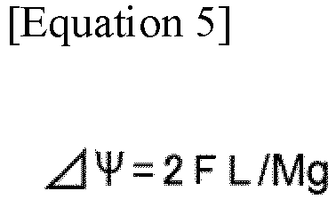
- Next, with reference to
FIGS. 10 to 12 , the display mode in which the operator Oa, Ob performs the swivel stop operation. - As shown in
FIG. 10 , the braking distance ofboom 7 is displayed in image region R1, R2. More specifically, since arrow-type image T extends in image region R1, R2, the braking distance ofboom 7 is displayed on the extension line of image T. Considering thathook 10 or load W suspended onhook 10 is vertically downward at the distal end portion ofboom 7, it can be said that the braking distance ofboom 7 is equal to the braking distance ofhook 10 or load W suspended onhook 10. Note that the value of the braking distance changes continuously in relation to the speed transition and the time transition. In the present application, the situation in which boom 7 swivels has been described, but the present invention is also applicable to a situation in which boom 7 extends or retracts and luffs up or down. Further, in addition to the swivel or the like ofboom 7, it is also applicable to a situation wherehook 10 ascends or descends. - Thus,
crane 1 according to the present application includes the driving devices (31 to 34) for performing the operation ofboom 7,control apparatus 20 for controlling the operating state of the driving devices (31 to 34),camera 41 for taking an image downward from the distal end portion ofboom 7, andimage display camera 41. Then, in the case where the motion ofboom 7 is stopped,control apparatus 20 generates filtered control signal Sf by applying filter F to basic control signal S of driving device (31 to 34), and controls drivedevice 20 based on filtered control signal Sf, and predicts the braking distance ofboom 7 to display onimage display such crane 1, operator Oa, Ob can grasp the surrounding condition ofhook 10 or load W suspended onhook 10 by viewingimage display boom 7. It is thus possible to perform an avoidance operation beforehook 10 or load W suspended onhook 10 collides with a building or the like. - In this regard, since the
present crane 1 can predict the position at which load W stops from the braking distance ofboom 7, marker Y of load W may be displayed at such a position. Marker Y is obtained by cutting out the image of load W taken bycamera 41, but is not limited thereto. For example, it may be a simple figure such as a circle or a rectangle. - As described above, in
crane 1 according to the present application,control apparatus 20 predicts the position at which load W stops, and displays marker Y of load W onimage display such crane 1, it is possible to easily determine whether load W collides with a building or the like from displayed marker Y of load W. Therefore, it is possible to perform the avoidance operation before load W collides with a building or the like. - In addition, since the
present crane 1 can predict the swing amount (amplitude) of load W from deceleration ofboom 7 or slinging length L ofhook 10, swing range Yr of load W in consideration of such a swing amount may be displayed. Swing range Yr has a large elliptical shape in the moving direction of load W (elliptical shape having the long axis along the moving direction of load W), but is not limited thereto. For example, it may be a straight line indicating a range or the like. - As described above, in
crane 1 according to the present application,control apparatus 20 predicts the swing amount of load W and displays the swing range Yr of load W onimage display such crane 1, it is possible to easily determine whether load W collides with a building or the like from displayed swing range Yr of load W. Therefore, it is possible to perform the avoidance operation before load W collides with a building or the like. - The above-mentioned technical idea can be applied even in a situation where load W is not suspended.
- That is, since the
present crane 1 can predict the position wherehook 10 stops from the braking distance ofboom 7, marker Z ofhook 10 may be displayed at such a position. Marker Z is obtained by cutting out the image ofhook 10 taken bycamera 41, but is not limited thereto. For example, it may be a simple figure such as a circle or a rectangle. - As described above, in
crane 1 according to the present application,control apparatus 20 predicts the position at whichhook 10 stops, and displays marker Z ofhook 10 onimage display such crane 1, it is possible to easily determine whetherhook 10 collides with a building or the like from displayed marker Z. Therefore, it is possible to perform an avoidance operation beforehook 10 collides with a building or the like. - In addition, since the
present crane 1 can predict the swing amount (amplitude) ofhook 10 from deceleration ofboom 7 or slinging length L ofhook 10, swing range Zr ofhook 10 in consideration of such a swing amount may be displayed. Swing range Zr has a large elliptical shape in the moving direction of hook 10 (elliptical shape having the long axis along the moving direction of hook 10), but is not limited thereto. For example, it may be a straight line indicating a range or the like. - As described above, in
crane 1 according to the present application,control apparatus 20 predicts the swing amount ofhook 10 and displays the swing range Zr ofhook 10 onimage display crane 1, it is possible to easily determine whetherhook 10 collide with the building or the like from displayed swing range Zr ofhook 10. Therefore, it is possible to perform an avoidance operation beforehook 10 collides with a building or the like. - Finally, although the present application uses notch filter F as a filter for generating filtered control signal Sf, it is not limited thereto. That is, the band-stop filter which can attenuate or reduce by a specific frequency range is sufficient. For example, it is a band limit filter, a band elimination filter, or the like.
- The present invention can be utilized for cranes.
-
- 1 Crane
- 2 Traveling body
- 3 Swivel body
- 7 Boom
- 8 Wire rope
- 9 Winch
- 10 Hook
- 12 Operating system
- 13 Remote operating terminal
- 20 Control apparatus
- 31 Swivel hydraulic motor (Driving device)
- 32 Extension/retraction hydraulic motor (Driving device)
- 33 Luffing hydraulic motor (Driving device)
- 34 Winding hydraulic motor (Driving device)
- 41 Camera
- 43 Image display
- 65 Image display
- F Notch filter (Filter)
- S Basic control signal
- Sf Filtered control signal
- W Load
- X Braking distance of a boom
- Y Marker of a load
- Z Marker of a hook
wherein the crane comprises:
Claims (5)
- A crane comprising:a boom;a wire rope hanging from the boom; anda hook ascending and descending by winding and unwinding of the wire rope;wherein the crane is configured to transport a load while suspending the load on the hook, wherein the crane comprises:a driving device for performing a motion of the boom;a control apparatus for controlling an operating state of the driving device;a camera for taking an image downward from a distal end portion of the boom; andan image display for displaying the image taken by the camera;wherein in a case where the motion of the boom is stopped, the control apparatus generates a filtered control signal by applying a filter to a basic control signal of the driving device and controls the driving device based on the filtered control signal, and predicts a braking distance of the boom to display the braking distance thereof on the image display.
- The crane according to claim 1, wherein the control apparatus predicts a position at which the load stops and displays a marker of the load on the image display.
- The crane according to claim 1 or 2, wherein the control apparatus predicts a swing amount of the load and displays a swing range of the load on the image display.
- The crane according to claim 1, wherein the control apparatus predicts a position at which the hook stops and displays a marker of the hook on the image display.
- The crane according to claim 1 or 4, wherein the control apparatus predicts a swing amount of the hook and displays a swing range of the hook on the image display.
Applications Claiming Priority (2)
| Application Number | Priority Date | Filing Date | Title |
|---|---|---|---|
| JP2018131035A JP7172206B2 (en) | 2018-07-10 | 2018-07-10 | crane |
| PCT/JP2019/020939 WO2020012798A1 (en) | 2018-07-10 | 2019-05-27 | Crane |
Publications (3)
| Publication Number | Publication Date |
|---|---|
| EP3822222A1 true EP3822222A1 (en) | 2021-05-19 |
| EP3822222A4 EP3822222A4 (en) | 2022-04-20 |
| EP3822222B1 EP3822222B1 (en) | 2023-10-18 |
Family
ID=69142876
Family Applications (1)
| Application Number | Title | Priority Date | Filing Date |
|---|---|---|---|
| EP19834252.9A Active EP3822222B1 (en) | 2018-07-10 | 2019-05-27 | Crane |
Country Status (5)
| Country | Link |
|---|---|
| US (1) | US11198596B2 (en) |
| EP (1) | EP3822222B1 (en) |
| JP (1) | JP7172206B2 (en) |
| CN (1) | CN112384466B (en) |
| WO (1) | WO2020012798A1 (en) |
Families Citing this family (7)
| Publication number | Priority date | Publication date | Assignee | Title |
|---|---|---|---|---|
| WO2020256106A1 (en) * | 2019-06-20 | 2020-12-24 | 株式会社タダノ | Movable range display system and crane equipped with movable range display system |
| JP7088432B2 (en) * | 2020-02-19 | 2022-06-21 | 株式会社タダノ | Hazard range display device for cranes and cranes |
| JP7323070B2 (en) * | 2020-06-03 | 2023-08-08 | 株式会社タダノ | Ground-breaking control device and crane |
| CN116553406B (en) * | 2022-01-30 | 2026-01-13 | 上海安川电动机器有限公司 | Swing back control method, device and equipment of slewing system and readable storage medium |
| JP7774490B2 (en) * | 2022-03-29 | 2025-11-21 | 住友重機械工業株式会社 | Crane operation support device and crane |
| CN117566589A (en) * | 2023-12-01 | 2024-02-20 | 张家港港务集团有限公司港埠分公司 | Method to avoid reciprocating swing of hook traveling terminal and lifting technology based on this method |
| CN120252533B (en) * | 2025-06-06 | 2025-08-12 | 德阳市特种设备检验所 | Device and method for measuring the amount of crane braking slide |
Family Cites Families (9)
| Publication number | Priority date | Publication date | Assignee | Title |
|---|---|---|---|---|
| JP4023749B2 (en) * | 2003-08-05 | 2007-12-19 | 新東工業株式会社 | Crane and its controller |
| JP4720457B2 (en) * | 2005-11-22 | 2011-07-13 | アイシン・エィ・ダブリュ株式会社 | Vehicle driving support method and driving support device |
| JP2011045167A (en) * | 2009-08-19 | 2011-03-03 | Nihon Univ | Driving support system, driving support method, and driving support program |
| JP5971994B2 (en) * | 2012-03-19 | 2016-08-17 | 株式会社タダノ | Crane work monitoring device |
| JP6192559B2 (en) | 2014-02-12 | 2017-09-06 | 三菱電機株式会社 | Crane equipment |
| JP2015196403A (en) * | 2014-03-31 | 2015-11-09 | 株式会社デンソー | Vehicular display control system |
| JP6772765B2 (en) * | 2016-11-07 | 2020-10-21 | 株式会社タダノ | Image display device |
| US10717631B2 (en) * | 2016-11-22 | 2020-07-21 | Manitowoc Crane Companies, Llc | Optical detection and analysis of crane hoist and rope |
| JP6834887B2 (en) * | 2017-09-29 | 2021-02-24 | 株式会社タダノ | crane |
-
2018
- 2018-07-10 JP JP2018131035A patent/JP7172206B2/en active Active
-
2019
- 2019-05-27 WO PCT/JP2019/020939 patent/WO2020012798A1/en not_active Ceased
- 2019-05-27 US US16/967,537 patent/US11198596B2/en active Active
- 2019-05-27 EP EP19834252.9A patent/EP3822222B1/en active Active
- 2019-05-27 CN CN201980044808.0A patent/CN112384466B/en active Active
Also Published As
| Publication number | Publication date |
|---|---|
| US11198596B2 (en) | 2021-12-14 |
| CN112384466B (en) | 2023-06-06 |
| WO2020012798A1 (en) | 2020-01-16 |
| CN112384466A (en) | 2021-02-19 |
| EP3822222B1 (en) | 2023-10-18 |
| JP2020007121A (en) | 2020-01-16 |
| EP3822222A4 (en) | 2022-04-20 |
| US20210214194A1 (en) | 2021-07-15 |
| JP7172206B2 (en) | 2022-11-16 |
Similar Documents
| Publication | Publication Date | Title |
|---|---|---|
| EP3822222B1 (en) | Crane | |
| EP3766821B1 (en) | Crane and crane control method | |
| EP2436637B1 (en) | Hook pose detecting equipment and crane | |
| EP3822219B1 (en) | Crane | |
| EP3279133A1 (en) | Display apparatus for traveling cranes and synchronizing aparatus for traveling cranes | |
| EP1652810B1 (en) | Crane and controller for the same | |
| EP3760569B1 (en) | Crane | |
| US11434113B2 (en) | Crane | |
| US11905145B2 (en) | Remote control terminal and work vehicle | |
| EP3828120A1 (en) | Crane and control system for crane | |
| EP3640194B1 (en) | Crane | |
| EP3831765A1 (en) | Crane | |
| EP4332048A1 (en) | Control device, crane, and method for controlling crane | |
| EP3763663B1 (en) | Crane and information display method | |
| EP3763656B1 (en) | Work vehicle | |
| EP3778463B1 (en) | Operation system comprising a work vehicle, a control apparatus , a remote operation terminal, and an information relay device. | |
| JP2019156532A (en) | Work vehicle and information display method in work vehicle |
Legal Events
| Date | Code | Title | Description |
|---|---|---|---|
| STAA | Information on the status of an ep patent application or granted ep patent |
Free format text: STATUS: THE INTERNATIONAL PUBLICATION HAS BEEN MADE |
|
| PUAI | Public reference made under article 153(3) epc to a published international application that has entered the european phase |
Free format text: ORIGINAL CODE: 0009012 |
|
| STAA | Information on the status of an ep patent application or granted ep patent |
Free format text: STATUS: REQUEST FOR EXAMINATION WAS MADE |
|
| 17P | Request for examination filed |
Effective date: 20210201 |
|
| AK | Designated contracting states |
Kind code of ref document: A1 Designated state(s): AL AT BE BG CH CY CZ DE DK EE ES FI FR GB GR HR HU IE IS IT LI LT LU LV MC MK MT NL NO PL PT RO RS SE SI SK SM TR |
|
| DAV | Request for validation of the european patent (deleted) | ||
| DAX | Request for extension of the european patent (deleted) | ||
| A4 | Supplementary search report drawn up and despatched |
Effective date: 20220323 |
|
| RIC1 | Information provided on ipc code assigned before grant |
Ipc: B66C 13/46 20060101ALI20220318BHEP Ipc: B66C 15/06 20060101ALI20220318BHEP Ipc: B66C 23/88 20060101ALI20220318BHEP Ipc: B66C 13/22 20060101AFI20220318BHEP |
|
| GRAP | Despatch of communication of intention to grant a patent |
Free format text: ORIGINAL CODE: EPIDOSNIGR1 |
|
| STAA | Information on the status of an ep patent application or granted ep patent |
Free format text: STATUS: GRANT OF PATENT IS INTENDED |
|
| INTG | Intention to grant announced |
Effective date: 20230508 |
|
| GRAS | Grant fee paid |
Free format text: ORIGINAL CODE: EPIDOSNIGR3 |
|
| GRAA | (expected) grant |
Free format text: ORIGINAL CODE: 0009210 |
|
| STAA | Information on the status of an ep patent application or granted ep patent |
Free format text: STATUS: THE PATENT HAS BEEN GRANTED |
|
| AK | Designated contracting states |
Kind code of ref document: B1 Designated state(s): AL AT BE BG CH CY CZ DE DK EE ES FI FR GB GR HR HU IE IS IT LI LT LU LV MC MK MT NL NO PL PT RO RS SE SI SK SM TR |
|
| REG | Reference to a national code |
Ref country code: GB Ref legal event code: FG4D |
|
| REG | Reference to a national code |
Ref country code: CH Ref legal event code: EP |
|
| REG | Reference to a national code |
Ref country code: IE Ref legal event code: FG4D |
|
| REG | Reference to a national code |
Ref country code: DE Ref legal event code: R096 Ref document number: 602019039757 Country of ref document: DE |
|
| REG | Reference to a national code |
Ref country code: LT Ref legal event code: MG9D |
|
| REG | Reference to a national code |
Ref country code: NL Ref legal event code: MP Effective date: 20231018 |
|
| REG | Reference to a national code |
Ref country code: AT Ref legal event code: MK05 Ref document number: 1622302 Country of ref document: AT Kind code of ref document: T Effective date: 20231018 |
|
| PG25 | Lapsed in a contracting state [announced via postgrant information from national office to epo] |
Ref country code: NL Free format text: LAPSE BECAUSE OF FAILURE TO SUBMIT A TRANSLATION OF THE DESCRIPTION OR TO PAY THE FEE WITHIN THE PRESCRIBED TIME-LIMIT Effective date: 20231018 |
|
| PG25 | Lapsed in a contracting state [announced via postgrant information from national office to epo] |
Ref country code: GR Free format text: LAPSE BECAUSE OF FAILURE TO SUBMIT A TRANSLATION OF THE DESCRIPTION OR TO PAY THE FEE WITHIN THE PRESCRIBED TIME-LIMIT Effective date: 20240119 |
|
| PG25 | Lapsed in a contracting state [announced via postgrant information from national office to epo] |
Ref country code: IS Free format text: LAPSE BECAUSE OF FAILURE TO SUBMIT A TRANSLATION OF THE DESCRIPTION OR TO PAY THE FEE WITHIN THE PRESCRIBED TIME-LIMIT Effective date: 20240218 |
|
| PG25 | Lapsed in a contracting state [announced via postgrant information from national office to epo] |
Ref country code: LT Free format text: LAPSE BECAUSE OF FAILURE TO SUBMIT A TRANSLATION OF THE DESCRIPTION OR TO PAY THE FEE WITHIN THE PRESCRIBED TIME-LIMIT Effective date: 20231018 |
|
| PG25 | Lapsed in a contracting state [announced via postgrant information from national office to epo] |
Ref country code: AT Free format text: LAPSE BECAUSE OF FAILURE TO SUBMIT A TRANSLATION OF THE DESCRIPTION OR TO PAY THE FEE WITHIN THE PRESCRIBED TIME-LIMIT Effective date: 20231018 |
|
| PG25 | Lapsed in a contracting state [announced via postgrant information from national office to epo] |
Ref country code: ES Free format text: LAPSE BECAUSE OF FAILURE TO SUBMIT A TRANSLATION OF THE DESCRIPTION OR TO PAY THE FEE WITHIN THE PRESCRIBED TIME-LIMIT Effective date: 20231018 |
|
| PG25 | Lapsed in a contracting state [announced via postgrant information from national office to epo] |
Ref country code: LT Free format text: LAPSE BECAUSE OF FAILURE TO SUBMIT A TRANSLATION OF THE DESCRIPTION OR TO PAY THE FEE WITHIN THE PRESCRIBED TIME-LIMIT Effective date: 20231018 Ref country code: IS Free format text: LAPSE BECAUSE OF FAILURE TO SUBMIT A TRANSLATION OF THE DESCRIPTION OR TO PAY THE FEE WITHIN THE PRESCRIBED TIME-LIMIT Effective date: 20240218 Ref country code: GR Free format text: LAPSE BECAUSE OF FAILURE TO SUBMIT A TRANSLATION OF THE DESCRIPTION OR TO PAY THE FEE WITHIN THE PRESCRIBED TIME-LIMIT Effective date: 20240119 Ref country code: ES Free format text: LAPSE BECAUSE OF FAILURE TO SUBMIT A TRANSLATION OF THE DESCRIPTION OR TO PAY THE FEE WITHIN THE PRESCRIBED TIME-LIMIT Effective date: 20231018 Ref country code: BG Free format text: LAPSE BECAUSE OF FAILURE TO SUBMIT A TRANSLATION OF THE DESCRIPTION OR TO PAY THE FEE WITHIN THE PRESCRIBED TIME-LIMIT Effective date: 20240118 Ref country code: AT Free format text: LAPSE BECAUSE OF FAILURE TO SUBMIT A TRANSLATION OF THE DESCRIPTION OR TO PAY THE FEE WITHIN THE PRESCRIBED TIME-LIMIT Effective date: 20231018 Ref country code: PT Free format text: LAPSE BECAUSE OF FAILURE TO SUBMIT A TRANSLATION OF THE DESCRIPTION OR TO PAY THE FEE WITHIN THE PRESCRIBED TIME-LIMIT Effective date: 20240219 |
|
| PG25 | Lapsed in a contracting state [announced via postgrant information from national office to epo] |
Ref country code: SE Free format text: LAPSE BECAUSE OF FAILURE TO SUBMIT A TRANSLATION OF THE DESCRIPTION OR TO PAY THE FEE WITHIN THE PRESCRIBED TIME-LIMIT Effective date: 20231018 Ref country code: RS Free format text: LAPSE BECAUSE OF FAILURE TO SUBMIT A TRANSLATION OF THE DESCRIPTION OR TO PAY THE FEE WITHIN THE PRESCRIBED TIME-LIMIT Effective date: 20231018 Ref country code: PL Free format text: LAPSE BECAUSE OF FAILURE TO SUBMIT A TRANSLATION OF THE DESCRIPTION OR TO PAY THE FEE WITHIN THE PRESCRIBED TIME-LIMIT Effective date: 20231018 Ref country code: NO Free format text: LAPSE BECAUSE OF FAILURE TO SUBMIT A TRANSLATION OF THE DESCRIPTION OR TO PAY THE FEE WITHIN THE PRESCRIBED TIME-LIMIT Effective date: 20240118 Ref country code: LV Free format text: LAPSE BECAUSE OF FAILURE TO SUBMIT A TRANSLATION OF THE DESCRIPTION OR TO PAY THE FEE WITHIN THE PRESCRIBED TIME-LIMIT Effective date: 20231018 Ref country code: HR Free format text: LAPSE BECAUSE OF FAILURE TO SUBMIT A TRANSLATION OF THE DESCRIPTION OR TO PAY THE FEE WITHIN THE PRESCRIBED TIME-LIMIT Effective date: 20231018 |
|
| PG25 | Lapsed in a contracting state [announced via postgrant information from national office to epo] |
Ref country code: DK Free format text: LAPSE BECAUSE OF FAILURE TO SUBMIT A TRANSLATION OF THE DESCRIPTION OR TO PAY THE FEE WITHIN THE PRESCRIBED TIME-LIMIT Effective date: 20231018 |
|
| REG | Reference to a national code |
Ref country code: DE Ref legal event code: R097 Ref document number: 602019039757 Country of ref document: DE |
|
| PG25 | Lapsed in a contracting state [announced via postgrant information from national office to epo] |
Ref country code: CZ Free format text: LAPSE BECAUSE OF FAILURE TO SUBMIT A TRANSLATION OF THE DESCRIPTION OR TO PAY THE FEE WITHIN THE PRESCRIBED TIME-LIMIT Effective date: 20231018 |
|
| PG25 | Lapsed in a contracting state [announced via postgrant information from national office to epo] |
Ref country code: SK Free format text: LAPSE BECAUSE OF FAILURE TO SUBMIT A TRANSLATION OF THE DESCRIPTION OR TO PAY THE FEE WITHIN THE PRESCRIBED TIME-LIMIT Effective date: 20231018 |
|
| PG25 | Lapsed in a contracting state [announced via postgrant information from national office to epo] |
Ref country code: SM Free format text: LAPSE BECAUSE OF FAILURE TO SUBMIT A TRANSLATION OF THE DESCRIPTION OR TO PAY THE FEE WITHIN THE PRESCRIBED TIME-LIMIT Effective date: 20231018 Ref country code: SK Free format text: LAPSE BECAUSE OF FAILURE TO SUBMIT A TRANSLATION OF THE DESCRIPTION OR TO PAY THE FEE WITHIN THE PRESCRIBED TIME-LIMIT Effective date: 20231018 Ref country code: RO Free format text: LAPSE BECAUSE OF FAILURE TO SUBMIT A TRANSLATION OF THE DESCRIPTION OR TO PAY THE FEE WITHIN THE PRESCRIBED TIME-LIMIT Effective date: 20231018 Ref country code: IT Free format text: LAPSE BECAUSE OF FAILURE TO SUBMIT A TRANSLATION OF THE DESCRIPTION OR TO PAY THE FEE WITHIN THE PRESCRIBED TIME-LIMIT Effective date: 20231018 Ref country code: EE Free format text: LAPSE BECAUSE OF FAILURE TO SUBMIT A TRANSLATION OF THE DESCRIPTION OR TO PAY THE FEE WITHIN THE PRESCRIBED TIME-LIMIT Effective date: 20231018 Ref country code: DK Free format text: LAPSE BECAUSE OF FAILURE TO SUBMIT A TRANSLATION OF THE DESCRIPTION OR TO PAY THE FEE WITHIN THE PRESCRIBED TIME-LIMIT Effective date: 20231018 Ref country code: CZ Free format text: LAPSE BECAUSE OF FAILURE TO SUBMIT A TRANSLATION OF THE DESCRIPTION OR TO PAY THE FEE WITHIN THE PRESCRIBED TIME-LIMIT Effective date: 20231018 |
|
| PLBE | No opposition filed within time limit |
Free format text: ORIGINAL CODE: 0009261 |
|
| STAA | Information on the status of an ep patent application or granted ep patent |
Free format text: STATUS: NO OPPOSITION FILED WITHIN TIME LIMIT |
|
| 26N | No opposition filed |
Effective date: 20240719 |
|
| PG25 | Lapsed in a contracting state [announced via postgrant information from national office to epo] |
Ref country code: SI Free format text: LAPSE BECAUSE OF FAILURE TO SUBMIT A TRANSLATION OF THE DESCRIPTION OR TO PAY THE FEE WITHIN THE PRESCRIBED TIME-LIMIT Effective date: 20231018 |
|
| PG25 | Lapsed in a contracting state [announced via postgrant information from national office to epo] |
Ref country code: SI Free format text: LAPSE BECAUSE OF FAILURE TO SUBMIT A TRANSLATION OF THE DESCRIPTION OR TO PAY THE FEE WITHIN THE PRESCRIBED TIME-LIMIT Effective date: 20231018 |
|
| REG | Reference to a national code |
Ref country code: CH Ref legal event code: PL |
|
| PG25 | Lapsed in a contracting state [announced via postgrant information from national office to epo] |
Ref country code: MC Free format text: LAPSE BECAUSE OF FAILURE TO SUBMIT A TRANSLATION OF THE DESCRIPTION OR TO PAY THE FEE WITHIN THE PRESCRIBED TIME-LIMIT Effective date: 20231018 |
|
| PG25 | Lapsed in a contracting state [announced via postgrant information from national office to epo] |
Ref country code: LU Free format text: LAPSE BECAUSE OF NON-PAYMENT OF DUE FEES Effective date: 20240527 |
|
| GBPC | Gb: european patent ceased through non-payment of renewal fee |
Effective date: 20240527 |
|
| PG25 | Lapsed in a contracting state [announced via postgrant information from national office to epo] |
Ref country code: MC Free format text: LAPSE BECAUSE OF FAILURE TO SUBMIT A TRANSLATION OF THE DESCRIPTION OR TO PAY THE FEE WITHIN THE PRESCRIBED TIME-LIMIT Effective date: 20231018 Ref country code: LU Free format text: LAPSE BECAUSE OF NON-PAYMENT OF DUE FEES Effective date: 20240527 Ref country code: CH Free format text: LAPSE BECAUSE OF NON-PAYMENT OF DUE FEES Effective date: 20240531 |
|
| REG | Reference to a national code |
Ref country code: BE Ref legal event code: MM Effective date: 20240531 |
|
| PG25 | Lapsed in a contracting state [announced via postgrant information from national office to epo] |
Ref country code: IE Free format text: LAPSE BECAUSE OF NON-PAYMENT OF DUE FEES Effective date: 20240527 |
|
| PG25 | Lapsed in a contracting state [announced via postgrant information from national office to epo] |
Ref country code: BE Free format text: LAPSE BECAUSE OF NON-PAYMENT OF DUE FEES Effective date: 20240531 |
|
| PG25 | Lapsed in a contracting state [announced via postgrant information from national office to epo] |
Ref country code: FR Free format text: LAPSE BECAUSE OF NON-PAYMENT OF DUE FEES Effective date: 20240531 |
|
| PG25 | Lapsed in a contracting state [announced via postgrant information from national office to epo] |
Ref country code: GB Free format text: LAPSE BECAUSE OF NON-PAYMENT OF DUE FEES Effective date: 20240527 |
|
| PGFP | Annual fee paid to national office [announced via postgrant information from national office to epo] |
Ref country code: DE Payment date: 20250519 Year of fee payment: 7 |
|
| PG25 | Lapsed in a contracting state [announced via postgrant information from national office to epo] |
Ref country code: HU Free format text: LAPSE BECAUSE OF FAILURE TO SUBMIT A TRANSLATION OF THE DESCRIPTION OR TO PAY THE FEE WITHIN THE PRESCRIBED TIME-LIMIT; INVALID AB INITIO Effective date: 20190527 |
|
| PG25 | Lapsed in a contracting state [announced via postgrant information from national office to epo] |
Ref country code: CY Free format text: LAPSE BECAUSE OF FAILURE TO SUBMIT A TRANSLATION OF THE DESCRIPTION OR TO PAY THE FEE WITHIN THE PRESCRIBED TIME-LIMIT; INVALID AB INITIO Effective date: 20190527 |
|
| PG25 | Lapsed in a contracting state [announced via postgrant information from national office to epo] |
Ref country code: FI Free format text: LAPSE BECAUSE OF FAILURE TO SUBMIT A TRANSLATION OF THE DESCRIPTION OR TO PAY THE FEE WITHIN THE PRESCRIBED TIME-LIMIT Effective date: 20231019 |