EP3822191B1 - Container closure with venting seal - Google Patents
Container closure with venting seal Download PDFInfo
- Publication number
- EP3822191B1 EP3822191B1 EP20206981.1A EP20206981A EP3822191B1 EP 3822191 B1 EP3822191 B1 EP 3822191B1 EP 20206981 A EP20206981 A EP 20206981A EP 3822191 B1 EP3822191 B1 EP 3822191B1
- Authority
- EP
- European Patent Office
- Prior art keywords
- container
- seal
- channel
- sidewall
- air pressure
- Prior art date
- Legal status (The legal status is an assumption and is not a legal conclusion. Google has not performed a legal analysis and makes no representation as to the accuracy of the status listed.)
- Active
Links
Images







Classifications
-
- B—PERFORMING OPERATIONS; TRANSPORTING
- B65—CONVEYING; PACKING; STORING; HANDLING THIN OR FILAMENTARY MATERIAL
- B65D—CONTAINERS FOR STORAGE OR TRANSPORT OF ARTICLES OR MATERIALS, e.g. BAGS, BARRELS, BOTTLES, BOXES, CANS, CARTONS, CRATES, DRUMS, JARS, TANKS, HOPPERS, FORWARDING CONTAINERS; ACCESSORIES, CLOSURES, OR FITTINGS THEREFOR; PACKAGING ELEMENTS; PACKAGES
- B65D51/00—Closures not otherwise provided for
- B65D51/16—Closures not otherwise provided for with means for venting air or gas
- B65D51/1605—Closures not otherwise provided for with means for venting air or gas whereby the interior of the container is maintained in permanent gaseous communication with the exterior
-
- B—PERFORMING OPERATIONS; TRANSPORTING
- B65—CONVEYING; PACKING; STORING; HANDLING THIN OR FILAMENTARY MATERIAL
- B65D—CONTAINERS FOR STORAGE OR TRANSPORT OF ARTICLES OR MATERIALS, e.g. BAGS, BARRELS, BOTTLES, BOXES, CANS, CARTONS, CRATES, DRUMS, JARS, TANKS, HOPPERS, FORWARDING CONTAINERS; ACCESSORIES, CLOSURES, OR FITTINGS THEREFOR; PACKAGING ELEMENTS; PACKAGES
- B65D51/00—Closures not otherwise provided for
- B65D51/16—Closures not otherwise provided for with means for venting air or gas
- B65D51/1633—Closures not otherwise provided for with means for venting air or gas whereby venting occurs by automatic opening of the closure, container or other element
- B65D51/1661—Closures not otherwise provided for with means for venting air or gas whereby venting occurs by automatic opening of the closure, container or other element by means of a passage for the escape of gas between the closure and the lip of the container mouth
-
- B—PERFORMING OPERATIONS; TRANSPORTING
- B65—CONVEYING; PACKING; STORING; HANDLING THIN OR FILAMENTARY MATERIAL
- B65D—CONTAINERS FOR STORAGE OR TRANSPORT OF ARTICLES OR MATERIALS, e.g. BAGS, BARRELS, BOTTLES, BOXES, CANS, CARTONS, CRATES, DRUMS, JARS, TANKS, HOPPERS, FORWARDING CONTAINERS; ACCESSORIES, CLOSURES, OR FITTINGS THEREFOR; PACKAGING ELEMENTS; PACKAGES
- B65D51/00—Closures not otherwise provided for
- B65D51/16—Closures not otherwise provided for with means for venting air or gas
- B65D51/1605—Closures not otherwise provided for with means for venting air or gas whereby the interior of the container is maintained in permanent gaseous communication with the exterior
- B65D51/1622—Closures not otherwise provided for with means for venting air or gas whereby the interior of the container is maintained in permanent gaseous communication with the exterior by means of a passage for the escape of gas between the closure and the lip of the container mouth
-
- B—PERFORMING OPERATIONS; TRANSPORTING
- B65—CONVEYING; PACKING; STORING; HANDLING THIN OR FILAMENTARY MATERIAL
- B65D—CONTAINERS FOR STORAGE OR TRANSPORT OF ARTICLES OR MATERIALS, e.g. BAGS, BARRELS, BOTTLES, BOXES, CANS, CARTONS, CRATES, DRUMS, JARS, TANKS, HOPPERS, FORWARDING CONTAINERS; ACCESSORIES, CLOSURES, OR FITTINGS THEREFOR; PACKAGING ELEMENTS; PACKAGES
- B65D1/00—Rigid or semi-rigid containers having bodies formed in one piece, e.g. by casting metallic material, by moulding plastics, by blowing vitreous material, by throwing ceramic material, by moulding pulped fibrous material or by deep-drawing operations performed on sheet material
- B65D1/02—Bottles or similar containers with necks or like restricted apertures, designed for pouring contents
-
- B—PERFORMING OPERATIONS; TRANSPORTING
- B65—CONVEYING; PACKING; STORING; HANDLING THIN OR FILAMENTARY MATERIAL
- B65D—CONTAINERS FOR STORAGE OR TRANSPORT OF ARTICLES OR MATERIALS, e.g. BAGS, BARRELS, BOTTLES, BOXES, CANS, CARTONS, CRATES, DRUMS, JARS, TANKS, HOPPERS, FORWARDING CONTAINERS; ACCESSORIES, CLOSURES, OR FITTINGS THEREFOR; PACKAGING ELEMENTS; PACKAGES
- B65D41/00—Caps, e.g. crown caps or crown seals, i.e. members having parts arranged for engagement with the external periphery of a neck or wall defining a pouring opening or discharge aperture; Protective cap-like covers for closure members, e.g. decorative covers of metal foil or paper
- B65D41/02—Caps or cap-like covers without lines of weakness, tearing strips, tags, or like opening or removal devices
- B65D41/04—Threaded or like caps or cap-like covers secured by rotation
- B65D41/0435—Threaded or like caps or cap-like covers secured by rotation with separate sealing elements
- B65D41/0442—Collars or rings
-
- B—PERFORMING OPERATIONS; TRANSPORTING
- B65—CONVEYING; PACKING; STORING; HANDLING THIN OR FILAMENTARY MATERIAL
- B65D—CONTAINERS FOR STORAGE OR TRANSPORT OF ARTICLES OR MATERIALS, e.g. BAGS, BARRELS, BOTTLES, BOXES, CANS, CARTONS, CRATES, DRUMS, JARS, TANKS, HOPPERS, FORWARDING CONTAINERS; ACCESSORIES, CLOSURES, OR FITTINGS THEREFOR; PACKAGING ELEMENTS; PACKAGES
- B65D53/00—Sealing or packing elements; Sealings formed by liquid or plastics material
- B65D53/04—Discs
-
- B—PERFORMING OPERATIONS; TRANSPORTING
- B65—CONVEYING; PACKING; STORING; HANDLING THIN OR FILAMENTARY MATERIAL
- B65D—CONTAINERS FOR STORAGE OR TRANSPORT OF ARTICLES OR MATERIALS, e.g. BAGS, BARRELS, BOTTLES, BOXES, CANS, CARTONS, CRATES, DRUMS, JARS, TANKS, HOPPERS, FORWARDING CONTAINERS; ACCESSORIES, CLOSURES, OR FITTINGS THEREFOR; PACKAGING ELEMENTS; PACKAGES
- B65D85/00—Containers, packaging elements or packages, specially adapted for particular articles or materials
- B65D85/70—Containers, packaging elements or packages, specially adapted for particular articles or materials for materials not otherwise provided for
- B65D85/72—Containers, packaging elements or packages, specially adapted for particular articles or materials for materials not otherwise provided for for edible or potable liquids, semiliquids, or plastic or pasty materials
Definitions
- Liquid containers can become over or under pressurized and the container damaged depending on the liquid to be contained and the ambient temperatures.
- a known type of container closure is a cap having a non-gas tight screw thread for engaging with a complimentary threaded neck of the container and a seal in the cap to form a substantially gas and liquid-tight seal with the container neck.
- One solution for unwanted negative pressurization of the container is incorporate a gas vent in the seal and/or the cap for venting between the ambient atmosphere and the interior of the container through openings existing between the screw threads of the cap and threads of the container neck.
- the document CN105966747 upon the disclosure of which the preamble of claim 1 is drafted, relates to a vessel, comprising a container and a cup lid, capable of releasing negative pressure automatically.
- a container closure comprises an outer cap, an inner cap, and a seal.
- the outer cap includes a top wall and an outer sidewall extending downward from the top wall.
- the inner cap is secured within the outer cap and includes a bottom wall and an inner sidewall extending upwardly from the bottom wall.
- the inner sidewall is offset from the outer sidewall to define a space between the outer cap and the inner cap for receiving an associated neck portion of an associated container.
- the seal is secured to the inner cap and includes a seal sidewall and a rim extending inwardly from the seal sidewall.
- the seal sidewall sealingly engages the inner sidewall and the rim sealingly overlaps the bottom wall.
- the inner cap together with the seal define an air pathway in fluid communication between the space between the outer and inner caps and an air opening formed on the bottom wall of the inner cap and selectively covered by the rim.
- FIG. 1-3 illustrate a container assembly 100 comprising a container 102 and an exemplary closure 104 according to the present disclosure which is complementary to the container.
- the container 102 may be configured to retain a desired substance, and in particular may be configured to retain the desired substance at a temperature that is either higher or lower than an ambient temperature.
- the container 102 is configured to be used as a beverage container, and may correspond to or resemble a bottle, jug, growler, vessel, carafe, or similar beverage container.
- the container 102 may be fashioned from any material having the desired properties for a beverage container, such as a stainless steel or a plastic formulation (e.g., a thermoplastic, or a thermosetting polymer).
- the container 102 may incorporate a double-walled construction, with the intervening space between the walls being substantially evacuated, so that the container is a vacuum-insulated container 102. Examples of appropriate vacuum-insulated containers are commercially available from HYDRO FLASK (Bend, Oregon).
- the container 102 includes body portion 110 and a neck portion 112 having a mouth 114 that provides access to an interior 118 of the container 102.
- the closure 104 is transitionable between an attached and a detached configuration with respect to the container neck portion 112.
- the closure 104 (which may alternatively be referred to as a cap or lid) may include one or more suitable structures and components configured so as to provide a sealing closure for the mouth 114 of the container 102.
- the closure 104 may include a first securing element (i.e., a first threading 120) that is complementary to a second securing element (i.e., a second threading 122) disposed on the neck portion 112.
- the first threading may be configured to mate with the second threading, so that the closure 104 may be secured to the neck portion 112 and thereby secured to and against mouth 114.
- additional and/or alternative configurations of securing elements may be used to secure the closure 104 against the container 102, for example, a snap-fit or crimped rim. In such cases the closure 104 and neck portion 112 of the container 102 need not be circular.
- the threaded connection does not form a gas tight seal between the closure 104 and the neck portion 112, so as to allow gas venting and pressure equalization as further described below.
- the exemplary closure 104 includes an outer cap assembly 130, an inner cap assembly 132 secured to the outer cap assembly, and a seal 134 secured to the inner cap assembly.
- the outer cap assembly 130 can comprise an outer cap 140 and, optionally, a cover member 142.
- the outer cap 140 includes a top wall 146 and an outer sidewall 148 extending downward from the top wall.
- An inner surface 150 of the outer sidewall 148 include the first threading 120.
- the cover member 142 which is complementary in shape to the outer cap 140, includes a top wall 154 and an outer sidewall 156.
- the top wall can include an opening 158 for exposing part of the top wall 146 which may be molded or inscribed to provide an aesthetic, instructional, or functional interface for a user of the container assembly 100.
- the cover member 142 is fixedly attached to the outer cap, for example, the cover member 142 can be overmolded onto the outer cap 140.
- Each of the outer cap 140 and the cover member 142 can be formed from a plastic, such as a thermoplastic, or a thermosetting polymer.
- the outer sidewall 156 of the cover member 142 may further include a grippable and/or manipulable surface configured to assist in attaching and/or detaching the closure 104 from the container 102.
- the inner cap assembly 132 is fixedly secured within the outer cap assembly 130.
- the inner cap assembly 132 comprises an inner cap 170, an insulation member 172, an insert 174, and a support 176.
- the inner cap 170 includes a bottom wall 180 and an inner sidewall 182 extending upwardly from the bottom wall. Similar to the top wall 146, the bottom wall 180 may be molded or inscribed to provide an aesthetic, instructional, or functional interface for a user of the container assembly 100.
- the inner sidewall 182 is offset from the outer sidewall 156 of the outer cap 140 to define a space 186 between the outer cap 140 and the inner cap 170 for receiving the neck portion 112 of the container 102. As best depicted in FIGS.
- the at least one groove is formed in the inner cap 170.
- the at least one groove includes a first groove or channel 190 and a second groove or channel 192 in communication with the first groove or channel 190.
- the first groove or channel 190 is formed in the inner sidewall 182 and extends circumferentially along a periphery of inner sidewall relative to a longitudinal axis CA of the closure 104 (the longitudinal axis is best depicted in FIGS. 7 and 8 ).
- the second groove or channel 192 is also formed in the inner sidewall 182 and extends axially relative to the longitudinal axis CA intersecting the first groove or channel 190.
- the inner sidewall 182 includes a first upper portion 196 and a second lower portion 198.
- the second lower portion 198 is offset inwardly (i.e., in a radial direction relative to the longitudinal axis CA) from the first upper portion 196 so as to define a first upper ledge 200 and a second lower ledge 202.
- the second ledge can be slightly offset upwardly from the bottom wall 180 and forms a radial extension of the bottom wall 180 which extends past the second lower portion 198.
- the first groove or channel 190 is defined by the second lower portion 198 and the first and second ledges 200, 202.
- a section of the second lower portion 198 can be bulged inwardly to define the second groove or channel 192 (see FIG. 9 ).
- the insulation member 172 and the insert 174 are positioned within the inner cap 170.
- the insulation member 172 includes a base 210 and a post 212 extending from the base.
- a first locating feature 204 for the second groove or channel 192 can be formed in the base 210.
- the insert 174 is connected to the insulation member 172.
- the insert 174 includes an outer sidewall 220 having an upper section 222 and a lower section 224 which are complementary in shape to the upper and lower portions 196, 198 of the inner sidewall 182 of the inner cap 170.
- the insert 174 further includes an inner sidewall 226 connected to the outer sidewall 220.
- the inner sidewall 226 together with the lower section 224 define an inner hub having a bore 230 that is complementary in shape to the insulation member 172. This allows the insert 174 to be matingly fitted or received over the insulation member 172. As shown, a second locating feature 232 for the second groove or channel 192 can be formed in the lower section 224, the second locating feature 232 received by the first locating feature 204 (see FIG. 9 ).
- the insert 174 can be further provided with a plurality of spaced reinforcing tabs 236 interconnecting the inner hub and outer sidewall 220. Further illustrated, the support 176 is received over the over the inner cap 170, particularly over the upper portion 196 of the inner sidewall 182 of the inner cap 170.
- the support 176 is ring-shaped having a sidewall 240 with an upper outwardly extending ledge 242 and a lower inwardly extending ledge 244.
- the insulation member 172 is sandwiched between and covered by the top wall 146 of the outer cap 140 and the bottom wall 180 of the inner cap 170, with the base 210 in contact with the bottom wall 180 and the post 212 in contact with the top wall 146.
- distal ends 250 of the reinforcing tabs 236 are spaced from the upper portion 196 of the inner sidewall 182 of the inner cap 170 to define offset regions 252 for locating flanges 254 depending from the top wall 146 of the outer cap 140.
- the seal 134 is provided to form a sealed connection between the neck portion 112 of the container 102 and the closure 104 when the closure is attached to (i.e., threaded onto) the neck portion.
- the seal 134 includes a seal sidewall 260 and a rim 262 extending inwardly from the seal sidewall, the rim 262 defining an opening 264.
- the seal sidewall 260 has an inverted U-shape in cross-section and includes an outer portion 270, an inner portion 272 and a top portion 274 interconnecting the outer and inner portions.
- the rim 262 extends inwardly from a lower free end of the inner portion 272.
- a circumferential shoulder 276 extends inwardly from a connected upper end of the inner portion 272.
- at least one groove or channel 280 can be formed in the top portion 274, the at least one groove or channel 280 extending radially on the top portion relative to the longitudinal axis CA (see FIGS. 7 and 8 ).
- a pair of grooves or channels 280, 282 can be formed on the top portion 274, the grooves or channels 280, 282 being angularly spaced (e.g., diametrically spaced) from one another relative to the longitudinal axis.
- the inner portion 272 of the seal sidewall 260 is secured to the lower portion 198 of the inner sidewall 182 of the inner cap 170.
- the top portion 274 is engaged against the upper ledge 200 of the lower portion 198 and the lower ledge 202 of the lower portion 198 is received between the rim 262 and the shoulder 276. Further, the rim 262 is sealingly engaged to the second lower ledge 202 of the bottom wall 180 of the inner cap 170, with the bottom wall 180 extending at least partially through the opening 264.
- the insulation member 172 may incorporate any suitable material, structure, or device configured to reduce heat transfer between upper and lower surfaces of the insulation member.
- the insulation member may include one or more plastics that may be the same or different than the plastics used for forming the other components of the closure 104.
- the insulation member 172 may include a plurality of internal voids or apertures configured so that the spaces formed by the voids decrease the thermal transfer due to conduction through the material of the insulation member 172.
- the seal 134 may include any material that creates or enhances an air-tight seal between the container 102 and the closure 104.
- the inner cap 170 together with the seal 134 define an air pathway 300 (see FIG. 9 ) in fluid communication between the space 186 between the outer and inner caps 140, 170 and an air opening 302 (see FIG. 8 ) formed on the bottom wall 180 of the inner cap 170 and selectively covered by the rim 262 of the seal 134.
- the air opening 302 is formed through the second lower ledge 202 of the bottom wall 180 outwardly of the lower portion 198 of the inner sidewall 182.
- a recessed portion 310 formed in the bottom wall near the air opening 302, which allows for ease of removal of the seal 134 from the inner cap 170.
- the air pathway 300 is defined by the first and second grooves or channels 190, 192 formed in the inner sidewall 182 of the inner cap 170 and covered by the seal 134.
- the air pathway 300 can also be defined by each of the grooves or channels 280, 282 optionally formed in the top portion 274 of the seal 134 and covered by the inner cap 170.
- the air pathway includes a first air pathway extending circumferentially about the longitudinal axis CA and formed by the first groove or channel 190 and the seal shoulder 276 and a second air pathway extending axially relative to the longitudinal axis CA and formed by the second groove or channel 192 and the seal shoulder 276.
- a third air pathway extending radial relative to the longitudinal axis CA can be formed by the top portion 274 (and optionally each of the grooves or channels 280, 282) and the first upper ledge 200 of the inner cap 170.
- the second air pathway intersects the first air pathway and the air opening 302, and the third air pathway intersects the first air pathway and is circumferentially spaced from the second air pathway.
- the lower end or ledge 244 of the support 176 received over the upper portion 196 of the inner sidewall 182 is both in contact with the top portion 274 of the seal 134 and can define an extension of each of the grooves or channels 280, 282.
- the grooves or channels 280, 282 are angularly spaced from the second groove or channel 192 relative to the longitudinal axis CA.
- first groove or channel 190 extends circumferentially along the inner sidewall 182 of the inner cap 170
- second groove or channel 192 extends axially from the first groove or channel 190 relative to the longitudinal axis CA and terminates at the air opening 302
- the grooves or channels 280, 282 of the seal 134 extend radially from the first groove or channel 190 relative to the longitudinal axis.
- an inner dimension of the seal sidewall 260 is less than an outer dimension of the lower portion 198 of the inner sidewall 182 so that when the seal 134 is fitted over the lower portion 198 the rim 262 is tensioned and biased against the second lower ledge 202 of the bottom wall 180 of the inner cap 170. This ensures that air opening 302 is normally closed or sealed by the rim 262 of the seal 134.
- the closure 104 is provided with the air pathway 300 allowing air flow between the interior 118 of the container 102 and the labyrinthine gap formed by the threaded connection of the closure 104 and container 102.
- a vacuum then formed within the interior 118 lifts that portion of the rim 262 covering the air opening 302 allowing ambient air to flow through the air pathway 300 and through the air opening 302 into the container.
- ambient air within the space 186 flows between the threaded connection, between the top portion 274 (and optionally through each of the grooves or channels 280, 282) and the first upper ledge 200 of the inner cap 170, into and through the first groove or channel 190, into and through the second groove or channel 192, and then into and through the air opening 302.
- This allows for equalization of interior air pressure of the container 102 and outside ambient air pressure.
- FIGS. 10-12 depict another embodiment of an exemplary closure 350 for the container assembly 100.
- the closure 350 includes the outer cap assembly 130 having the outer cap 140 and the cover member 142, the inner cap 170 secured to the outer cap 140, the seal 134 secured to the inner cap 170, and an insulation member 356.
- the insulation member 356 is positioned within the inner cap 170.
- the insulation member 356 includes a first cylindrical part 360 having a first diameter, and a second cylindrical part 362 having a second smaller diameter positioned below the first cylindrical part.
- the first and second cylindrical parts 360, 362 are complementary in shape to the respective upper and lower portions 196, 198 of the inner sidewall 182 of the inner cap 170.
- a locating feature 366 for the second groove or channel 192 of the inner cap 170 can be formed in the second cylindrical part 362.
- the insulation member 356 is sandwiched between and covered by the top wall 146 of the outer cap 140 and the bottom wall 180 of the inner cap 170, with the first cylindrical part 360 in contact with the top wall 146 and the second cylindrical part 362 in contact with the bottom wall 180.
- the insulation member 356 can be formed similar to the insulation member 172.
- the seal 134 which is mounted to the lower portion 198 of the inner sidewall 182 of the inner cap 170, is provided to form a sealed connection between the neck portion 112 of the container 102 and the closure 350 when the closure is attached to (i.e., threaded onto) the neck portion.
- the inner cap 170 together with the seal 134 define the air pathway 300 (see FIGS. 11 and 12 ) in fluid communication between the space 186 between the outer and inner caps 140, 170 and the air opening 302 formed on the bottom wall 180 of the inner cap 170.
- the air pathway 300 includes the first air pathway (i.e., the first groove or channel 190) extending circumferentially about the longitudinal axis CA, the second air pathway (i.e., the second groove or channel 192) extending axially relative to the longitudinal axis CA and intersecting the first air pathway and the air opening 302, and the third air pathway (i.e., between the seal 134 and the inner cap 170 and optionally the grooves or channels 280, 282) extending radial relative to the longitudinal axis CA, intersecting the first air pathway, and circumferentially spaced from the second air pathway.
- the first air pathway i.e., the first groove or channel 190
- the second air pathway i.e., the second groove or channel 192
- the third air pathway i.e., between the seal 134 and the inner cap 170 and optionally the grooves or channels 280, 282
- the closure 350 is adapted such that in a state where an interior pressure of the container 102 is greater than or equal to outside ambient air pressure, the air opening 302 is normally closed or sealed by the rim 262 of the seal 134 (see FIG. 13 ).
- the closure 350 is adapted such that in a state where an interior pressure of the container 102 is less than outside ambient air pressure, that portion of the rim 262 covering the air opening 302 is lifted (see FIG. 14 ) and ambient air flows through the air pathway 300, through the air opening 302 and into the container, again allowing for equalization of inside air pressure of the container and outside ambient air pressure.
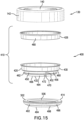
- FIGS. 15-17 depict another embodiment of an exemplary closure 400 for the container assembly 100.
- the closure 400 includes the outer cap assembly 130 having the outer cap 140 and the cover member 142, an inner cap assembly 410 secured to the outer cap 140, and a seal 414 secured to the inner cap assembly. Similar to the previous embodiments, an insulation member (not shown) can be positioned within the inner cap assembly 410.
- the inner cap assembly 410 comprises an inner cap 420 and a support 426.
- the inner cap 420 includes an inner sidewall 430 and a bottom member 432.
- the inner sidewall 430 is offset from the outer sidewall 156 of the outer cap 140 to define a space 436 between the outer cap 140 and the inner cap 420 for receiving a neck portion 440 of a container 442, which can be similar to the container 102 having a double-walled construction.
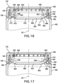
- the inner cap 420 has formed therein a first groove or channel 450 and a second groove or channel 452 in communication with the first groove or channel 450.
- the first groove or channel 450 is defined by an inwardly offset sidewall portion 456 (i.e., offset in an inward radial direction relative to a longitudinal axis CA of the closure 400 best depicted in FIGS. 16 and 17 ) formed in the inner sidewall 430 and extending circumferentially along a periphery of the inner sidewall 430 relative to the longitudinal axis CA.
- the sidewall portion 456 defines an upper ledge 460 and a lower ledge 462.
- the bottom member 432 which can be substantially saucer shaped, includes a sidewall 464 and a bottom wall 466.
- the lower ledge 462 extends outwardly (i.e., in an outward radial direction relative to the longitudinal axis CA) and circumferentially along a periphery the sidewall 464.
- a recessed portion 470 Provided on the sidewall 464 of the bottom member 432 is a recessed portion 470 and an air opening 472 extends through the lower ledge 462 and into the recessed portion 470.
- the air opening 472 is in direct communication with the second groove or channel 452.
- the support 426 is ring-shaped having a sidewall 480 dimensioned to be received over the inner sidewall 430 of the inner cap 420.
- the seal 414 includes a seal sidewall 492 and a rim 494 extending inwardly from the seal sidewall.
- the seal sidewall 492 has an inverted U-shape in cross-section and includes an outer portion 496, an inner portion 498 and a top portion 502 interconnecting the outer and inner portions ( FIG. 17 ).
- the rim 494 extends inwardly from a lower free end of the inner portion 498.
- a circumferential shoulder 506 extends inwardly from a connected upper end of the inner portion 498.
- the first groove or channel 450 is further defined by the shoulder 506 of the seal 414.
- the seal 414 is secured to the inner sidewall 430 of the inner cap 420 and the rim 494 is tensioned and biased against the sidewall 464 of the bottom member 432. Therefore, with the rim 494 sealingly engaged to the sidewall 464, the recessed portion 470 and the air opening 472 are normally closed or sealed by the seal 414.
- the inner cap 420 together with the seal 414 define an air pathway 520 in fluid communication between the space 436 between the outer and inner caps 140, 420 and the air opening 472 formed on the bottom member 432.
- the air pathway 520 includes the first air pathway (i.e., the first groove or channel 450) extending circumferentially about the longitudinal axis CA and the second air pathway (i.e., the second groove or channel 452) extending axially relative to the longitudinal axis CA and intersecting the first air pathway and the air opening 472.
- FIG. 18 is a detail cross-sectional view of the seal 414 in a state where an interior pressure of the container 442 is substantially equal to outside ambient air pressure.
- FIG. 19 is a detail cross-sectional view of the seal 414 in a state where a predetermined interior pressure of the container 442 is less than outside ambient air pressure. In this state, the vacuum formed within the container lifts that portion of the rim 494 covering the recessed portion 470 and the air opening 472. This allows ambient air to flow through the above described air pathway 520, through the air opening 472 and into the container, allowing for equalization of inside air pressure of the container and outside ambient air pressure.
- FIG. 20 is a detail cross-sectional view of the seal 414 in a state where a predetermined interior pressure of the container 442 is greater than outside ambient air pressure.
- that portion of the rim 494 covering the recessed portion 470 is at least partially deformed into the recessed portion, which, in turn, lifts that portion of the of the rim 494 away from the bottom member 432.
- This allows air from within the container to flow out the air opening 472, through the above described air pathway 520, into the space 436, and from there to ambient, again allowing for equalization of inside air pressure of the container and outside ambient air pressure.
Landscapes
- Engineering & Computer Science (AREA)
- Mechanical Engineering (AREA)
- Ceramic Engineering (AREA)
- Closures For Containers (AREA)
Description
- Liquid containers can become over or under pressurized and the container damaged depending on the liquid to be contained and the ambient temperatures. A known type of container closure is a cap having a non-gas tight screw thread for engaging with a complimentary threaded neck of the container and a seal in the cap to form a substantially gas and liquid-tight seal with the container neck. One solution for unwanted negative pressurization of the container is incorporate a gas vent in the seal and/or the cap for venting between the ambient atmosphere and the interior of the container through openings existing between the screw threads of the cap and threads of the container neck. The document
CN105966747 , upon the disclosure of which the preamble of claim 1 is drafted, relates to a vessel, comprising a container and a cup lid, capable of releasing negative pressure automatically. - According to one aspect, a container closure comprises an outer cap, an inner cap, and a seal. The outer cap includes a top wall and an outer sidewall extending downward from the top wall. The inner cap is secured within the outer cap and includes a bottom wall and an inner sidewall extending upwardly from the bottom wall. The inner sidewall is offset from the outer sidewall to define a space between the outer cap and the inner cap for receiving an associated neck portion of an associated container. The seal is secured to the inner cap and includes a seal sidewall and a rim extending inwardly from the seal sidewall. The seal sidewall sealingly engages the inner sidewall and the rim sealingly overlaps the bottom wall. The inner cap together with the seal define an air pathway in fluid communication between the space between the outer and inner caps and an air opening formed on the bottom wall of the inner cap and selectively covered by the rim.
- Preferred embodiments are defined by dependent claims.
-
-
FIG. 1 is an exploded perspective view of a container assembly including a container and an exemplary container closure according to one aspect of the present disclosure. -
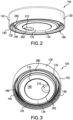
FIGS. 2 and 3 are perspective views of the closure ofFIG. 1 . -
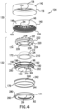
FIG. 4 is an exploded perspective view of the closure ofFIG. 1 . -
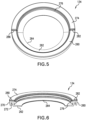
FIG. 5 is a perspective view of a seal of the closure ofFIG. 1 . -
FIG. 6 is a cross-sectional view ofFIG. 5 -
FIGS. 7-9 are cross-sectional views of the closure ofFIG. 1 . -
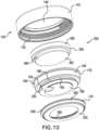
FIG. 10 is an exploded perspective view of an exemplary container closure according to another aspect of the present disclosure. -
FIGS. 11 and 12 are cross-sectional views ofFIG. 10 . -
FIG. 13 is a detail cross-sectional view of a seal in a state where an interior pressure of the container is greater than or substantially equal to outside ambient air pressure. -
FIG. 14 is a detail cross-sectional view of the seal in a state where an interior pressure of the container is less than outside ambient air pressure. -
FIG. 15 is an exploded perspective view of an exemplary container closure according to another aspect of the present disclosure. -
FIGS. 16 and 17 are cross-sectional views ofFIG. 15 . -
FIG. 18 is a detail cross-sectional view of a seal in a state where an interior pressure of the container is substantially equal to outside ambient air pressure. -
FIG. 19 is a detail cross-sectional view of the seal in a state where an interior pressure of the container is less than outside ambient air pressure. -
FIG. 20 is a detail cross-sectional view of the seal in a state where an interior pressure of the container is greater than outside ambient air pressure. - It should, of course, be understood that the description and drawings herein are merely illustrative and that various modifications and changes can be made in the structures disclosed without departing from the present disclosure. For purposes of description herein, spatially relative terms, such as "upper" and "lower" and the like, may be used to describe an element and/or feature's relationship to another element(s) and/or feature(s) as, for example, illustrated in the figures of the present disclosure.
- Referring now to the drawings, wherein like numerals refer to like parts throughout the several views,
FIG. 1-3 illustrate acontainer assembly 100 comprising acontainer 102 and anexemplary closure 104 according to the present disclosure which is complementary to the container. Thecontainer 102 may be configured to retain a desired substance, and in particular may be configured to retain the desired substance at a temperature that is either higher or lower than an ambient temperature. In one aspect of the disclosure, thecontainer 102 is configured to be used as a beverage container, and may correspond to or resemble a bottle, jug, growler, vessel, carafe, or similar beverage container. Thecontainer 102 may be fashioned from any material having the desired properties for a beverage container, such as a stainless steel or a plastic formulation (e.g., a thermoplastic, or a thermosetting polymer). In one aspect of the disclosure, thecontainer 102 may incorporate a double-walled construction, with the intervening space between the walls being substantially evacuated, so that the container is a vacuum-insulatedcontainer 102. Examples of appropriate vacuum-insulated containers are commercially available from HYDRO FLASK (Bend, Oregon). - The
container 102 includesbody portion 110 and aneck portion 112 having amouth 114 that provides access to aninterior 118 of thecontainer 102. Theclosure 104 is transitionable between an attached and a detached configuration with respect to thecontainer neck portion 112. The closure 104 (which may alternatively be referred to as a cap or lid) may include one or more suitable structures and components configured so as to provide a sealing closure for themouth 114 of thecontainer 102. By way of example, theclosure 104 may include a first securing element (i.e., a first threading 120) that is complementary to a second securing element (i.e., a second threading 122) disposed on theneck portion 112. That is, the first threading may be configured to mate with the second threading, so that theclosure 104 may be secured to theneck portion 112 and thereby secured to and againstmouth 114. It should be appreciated that additional and/or alternative configurations of securing elements may be used to secure theclosure 104 against thecontainer 102, for example, a snap-fit or crimped rim. In such cases theclosure 104 andneck portion 112 of thecontainer 102 need not be circular. When theclosure 104 is secured to thecontainer 102, the contents of thecontainer assembly 100 are not prone to leaking during routine handling and/or transport. However, the threaded connection does not form a gas tight seal between theclosure 104 and theneck portion 112, so as to allow gas venting and pressure equalization as further described below. - With additional reference to
FIG. 4 , theexemplary closure 104 includes anouter cap assembly 130, aninner cap assembly 132 secured to the outer cap assembly, and aseal 134 secured to the inner cap assembly. Theouter cap assembly 130 can comprise anouter cap 140 and, optionally, acover member 142. Theouter cap 140 includes atop wall 146 and anouter sidewall 148 extending downward from the top wall. Aninner surface 150 of theouter sidewall 148 include thefirst threading 120. Thecover member 142, which is complementary in shape to theouter cap 140, includes atop wall 154 and anouter sidewall 156. The top wall can include anopening 158 for exposing part of thetop wall 146 which may be molded or inscribed to provide an aesthetic, instructional, or functional interface for a user of thecontainer assembly 100. Thecover member 142 is fixedly attached to the outer cap, for example, thecover member 142 can be overmolded onto theouter cap 140. Each of theouter cap 140 and thecover member 142 can be formed from a plastic, such as a thermoplastic, or a thermosetting polymer. Theouter sidewall 156 of thecover member 142 may further include a grippable and/or manipulable surface configured to assist in attaching and/or detaching theclosure 104 from thecontainer 102. - The
inner cap assembly 132 is fixedly secured within theouter cap assembly 130. According to the present disclosure, theinner cap assembly 132 comprises aninner cap 170, aninsulation member 172, aninsert 174, and asupport 176. Theinner cap 170 includes abottom wall 180 and aninner sidewall 182 extending upwardly from the bottom wall. Similar to thetop wall 146, thebottom wall 180 may be molded or inscribed to provide an aesthetic, instructional, or functional interface for a user of thecontainer assembly 100. Theinner sidewall 182 is offset from theouter sidewall 156 of theouter cap 140 to define aspace 186 between theouter cap 140 and theinner cap 170 for receiving theneck portion 112 of thecontainer 102. As best depicted inFIGS. 7-9 , at least one groove or channel is formed in theinner cap 170. In the present embodiment, the at least one groove includes a first groove orchannel 190 and a second groove orchannel 192 in communication with the first groove orchannel 190. The first groove orchannel 190 is formed in theinner sidewall 182 and extends circumferentially along a periphery of inner sidewall relative to a longitudinal axis CA of the closure 104 (the longitudinal axis is best depicted inFIGS. 7 and 8 ). The second groove orchannel 192 is also formed in theinner sidewall 182 and extends axially relative to the longitudinal axis CA intersecting the first groove orchannel 190. More particularly, theinner sidewall 182 includes a firstupper portion 196 and a secondlower portion 198. The secondlower portion 198 is offset inwardly (i.e., in a radial direction relative to the longitudinal axis CA) from the firstupper portion 196 so as to define a firstupper ledge 200 and a secondlower ledge 202. The second ledge can be slightly offset upwardly from thebottom wall 180 and forms a radial extension of thebottom wall 180 which extends past the secondlower portion 198. The first groove orchannel 190 is defined by the secondlower portion 198 and the first andsecond ledges lower portion 198 can be bulged inwardly to define the second groove or channel 192 (seeFIG. 9 ). - In the depicted embodiment of
FIG. 4 ,7 and 8 , theinsulation member 172 and theinsert 174 are positioned within theinner cap 170. According to one aspect, theinsulation member 172 includes abase 210 and apost 212 extending from the base. Afirst locating feature 204 for the second groove orchannel 192 can be formed in thebase 210. Theinsert 174 is connected to theinsulation member 172. Theinsert 174 includes anouter sidewall 220 having anupper section 222 and alower section 224 which are complementary in shape to the upper andlower portions inner sidewall 182 of theinner cap 170. Theinsert 174 further includes aninner sidewall 226 connected to theouter sidewall 220. Theinner sidewall 226 together with thelower section 224 define an inner hub having abore 230 that is complementary in shape to theinsulation member 172. This allows theinsert 174 to be matingly fitted or received over theinsulation member 172. As shown, asecond locating feature 232 for the second groove orchannel 192 can be formed in thelower section 224, thesecond locating feature 232 received by the first locating feature 204 (seeFIG. 9 ). Theinsert 174 can be further provided with a plurality of spaced reinforcingtabs 236 interconnecting the inner hub andouter sidewall 220. Further illustrated, thesupport 176 is received over the over theinner cap 170, particularly over theupper portion 196 of theinner sidewall 182 of theinner cap 170. In the depicted aspect, thesupport 176 is ring-shaped having asidewall 240 with an upper outwardly extendingledge 242 and a lower inwardly extendingledge 244. In the assembled condition of theclosure 104, theinsulation member 172 is sandwiched between and covered by thetop wall 146 of theouter cap 140 and thebottom wall 180 of theinner cap 170, with the base 210 in contact with thebottom wall 180 and thepost 212 in contact with thetop wall 146. Further, distal ends 250 of the reinforcingtabs 236 are spaced from theupper portion 196 of theinner sidewall 182 of theinner cap 170 to define offsetregions 252 for locatingflanges 254 depending from thetop wall 146 of theouter cap 140. - The
seal 134 is provided to form a sealed connection between theneck portion 112 of thecontainer 102 and theclosure 104 when the closure is attached to (i.e., threaded onto) the neck portion. With particular reference toFIGS. 4-6 , theseal 134 includes aseal sidewall 260 and arim 262 extending inwardly from the seal sidewall, therim 262 defining anopening 264. According to the depicted aspect, theseal sidewall 260 has an inverted U-shape in cross-section and includes anouter portion 270, aninner portion 272 and atop portion 274 interconnecting the outer and inner portions. Therim 262 extends inwardly from a lower free end of theinner portion 272. Acircumferential shoulder 276 extends inwardly from a connected upper end of theinner portion 272. Further, at least one groove orchannel 280 can be formed in thetop portion 274, the at least one groove orchannel 280 extending radially on the top portion relative to the longitudinal axis CA (seeFIGS. 7 and 8 ). In the present disclosure, a pair of grooves orchannels top portion 274, the grooves orchannels FIGS. 7 and 8 , theinner portion 272 of theseal sidewall 260 is secured to thelower portion 198 of theinner sidewall 182 of theinner cap 170. Thetop portion 274 is engaged against theupper ledge 200 of thelower portion 198 and thelower ledge 202 of thelower portion 198 is received between therim 262 and theshoulder 276. Further, therim 262 is sealingly engaged to the secondlower ledge 202 of thebottom wall 180 of theinner cap 170, with thebottom wall 180 extending at least partially through theopening 264. - Each of the
inner cap 170, theinsert 174, and thesupport 176 can be formed from a plastic, such as a thermoplastic, or a thermosetting polymer. Theinsulation member 172 may incorporate any suitable material, structure, or device configured to reduce heat transfer between upper and lower surfaces of the insulation member. For example, the insulation member may include one or more plastics that may be the same or different than the plastics used for forming the other components of theclosure 104. In addition to the incorporation of an insulating material, theinsulation member 172 may include a plurality of internal voids or apertures configured so that the spaces formed by the voids decrease the thermal transfer due to conduction through the material of theinsulation member 172. Theseal 134 may include any material that creates or enhances an air-tight seal between thecontainer 102 and theclosure 104. - According to the present disclosure, the
inner cap 170 together with theseal 134 define an air pathway 300 (seeFIG. 9 ) in fluid communication between thespace 186 between the outer andinner caps FIG. 8 ) formed on thebottom wall 180 of theinner cap 170 and selectively covered by therim 262 of theseal 134. As illustrated, theair opening 302 is formed through the secondlower ledge 202 of thebottom wall 180 outwardly of thelower portion 198 of theinner sidewall 182. Further depicted is a recessedportion 310 formed in the bottom wall near theair opening 302, which allows for ease of removal of theseal 134 from theinner cap 170. According to the present embodiment, theair pathway 300 is defined by the first and second grooves orchannels inner sidewall 182 of theinner cap 170 and covered by theseal 134. Theair pathway 300 can also be defined by each of the grooves orchannels top portion 274 of theseal 134 and covered by theinner cap 170. More particularly, the air pathway includes a first air pathway extending circumferentially about the longitudinal axis CA and formed by the first groove orchannel 190 and theseal shoulder 276 and a second air pathway extending axially relative to the longitudinal axis CA and formed by the second groove orchannel 192 and theseal shoulder 276. Due to tolerances between theinner cap 170 and theseal 134 connected thereto, ambient air is capable of flowing between thetop portion 274 of theseal 134 and the firstupper ledge 200 of the secondlower portion 198 of theinner sidewall 182 of theinner cap 170. To facilitate this airflow, the grooves orchannels top portion 274. Therefore, a third air pathway extending radial relative to the longitudinal axis CA can be formed by the top portion 274 (and optionally each of the grooves orchannels 280, 282) and the firstupper ledge 200 of theinner cap 170. The second air pathway intersects the first air pathway and theair opening 302, and the third air pathway intersects the first air pathway and is circumferentially spaced from the second air pathway. - As depicted in
FIGS. 7 and 8 , the lower end orledge 244 of thesupport 176 received over theupper portion 196 of theinner sidewall 182 is both in contact with thetop portion 274 of theseal 134 and can define an extension of each of the grooves orchannels FIGS. 7-9 , the grooves orchannels channel 192 relative to the longitudinal axis CA. Again, the first groove orchannel 190 extends circumferentially along theinner sidewall 182 of theinner cap 170, the second groove orchannel 192 extends axially from the first groove orchannel 190 relative to the longitudinal axis CA and terminates at theair opening 302, and the grooves orchannels seal 134 extend radially from the first groove orchannel 190 relative to the longitudinal axis. Further, an inner dimension of theseal sidewall 260 is less than an outer dimension of thelower portion 198 of theinner sidewall 182 so that when theseal 134 is fitted over thelower portion 198 therim 262 is tensioned and biased against the secondlower ledge 202 of thebottom wall 180 of theinner cap 170. This ensures thatair opening 302 is normally closed or sealed by therim 262 of theseal 134. - Therefore, the
closure 104 is provided with theair pathway 300 allowing air flow between the interior 118 of thecontainer 102 and the labyrinthine gap formed by the threaded connection of theclosure 104 andcontainer 102. When thecontainer 102 is under pressurized with respect to outside ambient air pressure, a vacuum then formed within the interior 118 lifts that portion of therim 262 covering theair opening 302 allowing ambient air to flow through theair pathway 300 and through theair opening 302 into the container. Particularly, ambient air within thespace 186 flows between the threaded connection, between the top portion 274 (and optionally through each of the grooves orchannels 280, 282) and the firstupper ledge 200 of theinner cap 170, into and through the first groove orchannel 190, into and through the second groove orchannel 192, and then into and through theair opening 302. This allows for equalization of interior air pressure of thecontainer 102 and outside ambient air pressure. -
FIGS. 10-12 depict another embodiment of anexemplary closure 350 for thecontainer assembly 100. Theclosure 350 includes theouter cap assembly 130 having theouter cap 140 and thecover member 142, theinner cap 170 secured to theouter cap 140, theseal 134 secured to theinner cap 170, and aninsulation member 356. Theinsulation member 356 is positioned within theinner cap 170. According to one aspect, theinsulation member 356 includes a firstcylindrical part 360 having a first diameter, and a secondcylindrical part 362 having a second smaller diameter positioned below the first cylindrical part. As depicted, the first and secondcylindrical parts lower portions inner sidewall 182 of theinner cap 170. A locatingfeature 366 for the second groove orchannel 192 of theinner cap 170 can be formed in the secondcylindrical part 362. In the assembled condition of theclosure 104, theinsulation member 356 is sandwiched between and covered by thetop wall 146 of theouter cap 140 and thebottom wall 180 of theinner cap 170, with the firstcylindrical part 360 in contact with thetop wall 146 and the secondcylindrical part 362 in contact with thebottom wall 180. Theinsulation member 356 can be formed similar to theinsulation member 172. - With reference also to
FIGS. 13 and 14 , theseal 134, which is mounted to thelower portion 198 of theinner sidewall 182 of theinner cap 170, is provided to form a sealed connection between theneck portion 112 of thecontainer 102 and theclosure 350 when the closure is attached to (i.e., threaded onto) the neck portion. Again, theinner cap 170 together with theseal 134 define the air pathway 300 (seeFIGS. 11 and 12 ) in fluid communication between thespace 186 between the outer andinner caps air opening 302 formed on thebottom wall 180 of theinner cap 170. Theair pathway 300 includes the first air pathway (i.e., the first groove or channel 190) extending circumferentially about the longitudinal axis CA, the second air pathway (i.e., the second groove or channel 192) extending axially relative to the longitudinal axis CA and intersecting the first air pathway and theair opening 302, and the third air pathway (i.e., between theseal 134 and theinner cap 170 and optionally the grooves orchannels 280, 282) extending radial relative to the longitudinal axis CA, intersecting the first air pathway, and circumferentially spaced from the second air pathway. Theclosure 350 is adapted such that in a state where an interior pressure of thecontainer 102 is greater than or equal to outside ambient air pressure, theair opening 302 is normally closed or sealed by therim 262 of the seal 134 (seeFIG. 13 ). Theclosure 350 is adapted such that in a state where an interior pressure of thecontainer 102 is less than outside ambient air pressure, that portion of therim 262 covering theair opening 302 is lifted (seeFIG. 14 ) and ambient air flows through theair pathway 300, through theair opening 302 and into the container, again allowing for equalization of inside air pressure of the container and outside ambient air pressure. -
FIGS. 15-17 depict another embodiment of anexemplary closure 400 for thecontainer assembly 100. Theclosure 400 includes theouter cap assembly 130 having theouter cap 140 and thecover member 142, aninner cap assembly 410 secured to theouter cap 140, and aseal 414 secured to the inner cap assembly. Similar to the previous embodiments, an insulation member (not shown) can be positioned within theinner cap assembly 410. According to the present disclosure, theinner cap assembly 410 comprises aninner cap 420 and asupport 426. Theinner cap 420 includes aninner sidewall 430 and abottom member 432. Theinner sidewall 430 is offset from theouter sidewall 156 of theouter cap 140 to define aspace 436 between theouter cap 140 and theinner cap 420 for receiving aneck portion 440 of acontainer 442, which can be similar to thecontainer 102 having a double-walled construction. - As depicted, the
inner cap 420 has formed therein a first groove orchannel 450 and a second groove orchannel 452 in communication with the first groove orchannel 450. The first groove orchannel 450 is defined by an inwardly offset sidewall portion 456 (i.e., offset in an inward radial direction relative to a longitudinal axis CA of theclosure 400 best depicted inFIGS. 16 and 17 ) formed in theinner sidewall 430 and extending circumferentially along a periphery of theinner sidewall 430 relative to the longitudinal axis CA. Thesidewall portion 456 defines anupper ledge 460 and alower ledge 462. Thebottom member 432, which can be substantially saucer shaped, includes asidewall 464 and abottom wall 466. Thelower ledge 462 extends outwardly (i.e., in an outward radial direction relative to the longitudinal axis CA) and circumferentially along a periphery thesidewall 464. Provided on thesidewall 464 of thebottom member 432 is a recessedportion 470 and anair opening 472 extends through thelower ledge 462 and into the recessedportion 470. Theair opening 472 is in direct communication with the second groove orchannel 452. In the depicted aspect, thesupport 426 is ring-shaped having asidewall 480 dimensioned to be received over theinner sidewall 430 of theinner cap 420. - Similar to the
seal 134 described above, theseal 414 includes aseal sidewall 492 and arim 494 extending inwardly from the seal sidewall. According to the depicted aspect, theseal sidewall 492 has an inverted U-shape in cross-section and includes anouter portion 496, aninner portion 498 and atop portion 502 interconnecting the outer and inner portions (FIG. 17 ). Therim 494 extends inwardly from a lower free end of theinner portion 498. Acircumferential shoulder 506 extends inwardly from a connected upper end of theinner portion 498. The first groove orchannel 450 is further defined by theshoulder 506 of theseal 414. InFIGS. 16 and 17 , theseal 414 is secured to theinner sidewall 430 of theinner cap 420 and therim 494 is tensioned and biased against thesidewall 464 of thebottom member 432. Therefore, with therim 494 sealingly engaged to thesidewall 464, the recessedportion 470 and theair opening 472 are normally closed or sealed by theseal 414. - With reference now to
FIGS. 18-20 , similar to the previous embodiments, theinner cap 420 together with theseal 414 define anair pathway 520 in fluid communication between thespace 436 between the outer andinner caps air opening 472 formed on thebottom member 432. Theair pathway 520 includes the first air pathway (i.e., the first groove or channel 450) extending circumferentially about the longitudinal axis CA and the second air pathway (i.e., the second groove or channel 452) extending axially relative to the longitudinal axis CA and intersecting the first air pathway and theair opening 472. Similar to the previous embodiments, due to tolerances between theinner cap 420 and theseal 414 connected thereto, airflow is capable between thetop portion 502 of theseal 414 and theupper ledge 460 of theinner sidewall 430 of theinner cap 420. Therefore, a third air pathway extending radial relative to the longitudinal axis CA can be formed by thetop portion 502 and theupper ledge 460 of theinner cap 420. The third air pathway intersects the first air pathway and the second air pathway.FIG. 18 is a detail cross-sectional view of theseal 414 in a state where an interior pressure of thecontainer 442 is substantially equal to outside ambient air pressure. As shown, theseal sidewall 492 is sealingly engaged to theneck portion 440 of thecontainer 442 and therim 494 is sealingly engaged to thesidewall 464 of thebottom member 432. The recessedportion 470 and, in turn, theair opening 472, is covered and sealed by therim 494.FIG. 19 is a detail cross-sectional view of theseal 414 in a state where a predetermined interior pressure of thecontainer 442 is less than outside ambient air pressure. In this state, the vacuum formed within the container lifts that portion of therim 494 covering the recessedportion 470 and theair opening 472. This allows ambient air to flow through the above describedair pathway 520, through theair opening 472 and into the container, allowing for equalization of inside air pressure of the container and outside ambient air pressure. Particularly, after therim 494 is lifted away from thebottom member 432, ambient air within thespace 436 flows between the threaded connection, between theupper portion 502 of theseal 414 of theupper edge 460 of theinner cap 420, into and through the first groove orchannel 450, into and through the second groove orchannel 452, and into and through theair opening 472 to the interior of the container.FIG. 20 is a detail cross-sectional view of theseal 414 in a state where a predetermined interior pressure of thecontainer 442 is greater than outside ambient air pressure. In this state, that portion of therim 494 covering the recessedportion 470 is at least partially deformed into the recessed portion, which, in turn, lifts that portion of the of therim 494 away from thebottom member 432. This allows air from within the container to flow out theair opening 472, through the above describedair pathway 520, into thespace 436, and from there to ambient, again allowing for equalization of inside air pressure of the container and outside ambient air pressure.
Claims (14)
- A container closure (104, 350, 400), comprising:an outer cap (140) including a top wall (146) and an outer sidewall (148) extending downward from the top wall;an inner cap (170, 420) secured within the outer cap (140), the inner cap (170, 420) including a bottom wall (180, 432) and an inner sidewall (182, 430) extending upwardly from the bottom wall (180, 432), the inner sidewall (182, 430) is offset from the outer sidewall (148) to define a space (186, 436) between the outer cap (140) and the inner cap (170, 420) for receiving an associated neck portion (112, 440) of an associated container (102, 442);a seal (134, 414) secured to the inner cap (170, 420), the seal (134, 414) including a seal sidewall (260, 492) and a rim (262, 494) extending inwardly from the seal sidewall, the seal sidewall (260, 492) sealingly engaging the inner sidewall (182, 430) and the rim (262, 494) sealingly overlapping the bottom wall (180, 432),characterized in that the inner cap (170, 420) together with the seal (134, 414) define an air pathway (300, 520) in fluid communication between the space (186, 436) between the outer and inner caps and an air opening (302, 472) formed on the bottom wall (180, 432) of the inner cap (170, 420) and selectively covered by the rim (262, 494).
- The container closure of claim 1, wherein the air pathway (300, 520) is at least partially defined by at least one groove (190, 192, 450, 452) formed in the inner cap (170, 420) and covered by the seal (134, 414).
- The container closure of claim 2, wherein the at least one groove is a first groove (190, 450) formed in and along a periphery of the inner sidewall and a second groove (192, 452) formed in the inner sidewall and intersecting the first groove.
- The container closure of claim 3, wherein the air pathway (300) is at least partially defined by at least one channel (280, 282) formed in the seal (134) and covered by the inner cap (170).
- The container closure of claim 4, wherein the container closure defines a longitudinal axis (CA), and the second groove (192) is angularly spaced from the at least one channel (280, 282) relative to the longitudinal axis.
- The container closure of claim 4, wherein the container closure defines a longitudinal axis (CA), the at least one channel is a first channel (280) and a second channel (282) circumferentially spaced from the first channel relative to the longitudinal axis, and one of the first channel and the second channel intersects the second groove (192).
- The container closure of claim 2, wherein the at least one groove (190, 450) separates the inner sidewall into an upper portion (196) and a lower portion (198), and an inner dimension of the seal (134, 414) is less than an outer dimension of the lower portion (196) so that when the seal is fitted over the lower portion the rim (262, 494) is tensioned and biased against the bottom wall (180, 432).
- The container closure of one of claims 1 to 7, wherein the container closure defines a longitudinal axis (CA), the air pathway (300, 520) is defined by a first channel (190, 450) extending circumferentially along the inner cap (170, 420) and a second channel (192, 452) extending axially from the first channel relative to the longitudinal axis.
- The container closure of claim 8, wherein the first channel (190, 450) extends circumferentially along the inner sidewall (182, 430) and the second channel (192, 452) fluidly connects the first channel and the air opening (302, 472) in the bottom wall (180, 432).
- The container closure of one of claims 1 to 9, wherein the bottom wall (180, 432) includes a recessed portion (310, 470) and the air opening (302, 472) is located in the recessed portion.
- A combination of a container closure (104, 350, 400) of one of claims 1 to 10 and of a container (102, 442), the container including a neck portion (112, 440), and the container closure transitionable between an attached and a detached configuration with respect to the container neck portion (112, 440),
wherein the rim (262, 494) is configured to be lifted away from the bottom wall when a predetermined interior air pressure of the container is less than outside ambient air pressure, allowing ambient air to flow through the air pathway (300, 520) and through the air opening (302, 472) into the container to equalize interior air pressure of the container and outside ambient air pressure. - The combination of claim 11, wherein the bottom wall (432) includes a recessed portion (470) and the air opening (472) is located in the recessed portion, and the rim (494) is configured to be at least partially deformed into the recessed portion when a predetermined interior air pressure of the container is greater than outside ambient air pressure, allowing inside air to flow out through the air opening (472) and through the air pathway (520) to ambient to equalize interior air pressure of the container and outside ambient air pressure.
- A combination of a container closure (400) of one of claims 1 to 10 and of a container (422), the container including a neck portion (440), and the container closure transitionable between an attached and a detached configuration with respect to the container neck portion,
wherein the rim (494) is configured to be lifted away from the bottom wall (432) when a predetermined interior air pressure of the container is greater than outside ambient air pressure, allowing inside air to flow out through the air opening (472) and through the air pathway (520) to ambient to equalize interior air pressure of the container and outside ambient air pressure. - The combination of claim 13, wherein the bottom wall (432) includes a recessed portion (470) and the air opening (472) is located in the recessed portion, and the rim (494) is configured to be at least partially deformed into the recessed portion (470) when a predetermined interior air pressure of the container is greater than outside ambient air pressure.
Applications Claiming Priority (1)
| Application Number | Priority Date | Filing Date | Title |
|---|---|---|---|
| US16/684,712 US11535433B2 (en) | 2019-11-15 | 2019-11-15 | Container closure with venting seal |
Publications (2)
| Publication Number | Publication Date |
|---|---|
| EP3822191A1 EP3822191A1 (en) | 2021-05-19 |
| EP3822191B1 true EP3822191B1 (en) | 2025-01-01 |
Family
ID=73343948
Family Applications (1)
| Application Number | Title | Priority Date | Filing Date |
|---|---|---|---|
| EP20206981.1A Active EP3822191B1 (en) | 2019-11-15 | 2020-11-11 | Container closure with venting seal |
Country Status (3)
| Country | Link |
|---|---|
| US (1) | US11535433B2 (en) |
| EP (1) | EP3822191B1 (en) |
| CN (1) | CN112810994B (en) |
Families Citing this family (14)
| Publication number | Priority date | Publication date | Assignee | Title |
|---|---|---|---|---|
| CN114026028B (en) * | 2019-05-27 | 2025-01-07 | Rpc布兰姆拉格股份有限公司 | Closure device for container |
| US11358760B2 (en) * | 2019-09-10 | 2022-06-14 | Helen Of Troy Limited | Straw lid assembly |
| USD941636S1 (en) * | 2020-03-19 | 2022-01-25 | Helen Of Troy Limited | Vacuum insulated bowl |
| USD957196S1 (en) | 2020-10-27 | 2022-07-12 | Yeti Coolers, Llc | Bottle |
| USD1036936S1 (en) | 2021-10-26 | 2024-07-30 | Yeti Coolers, Llc | Bottle |
| USD1015058S1 (en) * | 2022-02-18 | 2024-02-20 | Ever Vessel Pty Ltd | Drinking vessel lid |
| USD1014179S1 (en) * | 2022-02-18 | 2024-02-13 | Ever Vessel Pty Ltd | Drinking vessel lid |
| US12528058B2 (en) | 2022-03-24 | 2026-01-20 | Spritz, Inc. | Container for liquid and method associated therewith |
| CN115339760B (en) * | 2022-10-15 | 2023-01-06 | 北矿化学科技(沧州)有限公司 | Packaging cover with breather valve |
| USD1140644S1 (en) | 2022-10-26 | 2026-08-11 | Yeti Coolers, Llc | Bottle |
| USD1126670S1 (en) | 2022-10-26 | 2026-05-19 | Yeti Coolers, Llc | Bottle |
| USD1050803S1 (en) | 2022-12-16 | 2024-11-12 | Yeti Coolers, Llc | Lid |
| USD1050801S1 (en) | 2022-12-16 | 2024-11-12 | Yeti Coolers, Llc | Lid |
| US12703541B2 (en) * | 2024-08-30 | 2026-08-11 | Closure Systems International Inc. | Closure with plug and container |
Family Cites Families (22)
| Publication number | Priority date | Publication date | Assignee | Title |
|---|---|---|---|---|
| US3022918A (en) | 1960-06-13 | 1962-02-27 | Plas Tainer Inc | Sealing means |
| US3174641A (en) | 1963-03-11 | 1965-03-23 | Pacific Ind Inc | Vented closure assembly |
| US3308981A (en) * | 1965-02-26 | 1967-03-14 | Container Corp | Venting closure for containers |
| BE759636A (en) | 1969-12-10 | 1971-04-30 | Diamond Int Corp | CONTAINER EQUIPPED WITH A COMBINED BODY IN THE FORM OF A SEAL AND A VALVE |
| PH12385A (en) | 1975-07-09 | 1979-01-29 | Procter & Gamble | Venting closure assembly |
| US4685580A (en) | 1986-04-18 | 1987-08-11 | Tbl Development Corporation | Anti-panelling container closure |
| CN2419917Y (en) * | 2000-03-15 | 2001-02-21 | 翁友平 | Heat insulation cup |
| WO2006124591A1 (en) | 2005-05-13 | 2006-11-23 | Chemtura Corporation | Moisture absorbent scavenger and vacuum relief device for chemical containers |
| US7588142B1 (en) * | 2005-11-18 | 2009-09-15 | Rexam Closures And Containers Inc. | Additive delivery system closure |
| US8584876B2 (en) * | 2007-07-05 | 2013-11-19 | Kraft Foods Group Brands Llc | Food containers adapted for accommodating pressure changes using skip seals and methods of manufacture |
| US8430259B2 (en) | 2008-04-04 | 2013-04-30 | Stokely-Van Camp, Inc. | Closure with flexible diaphragm |
| US8875927B2 (en) | 2009-09-23 | 2014-11-04 | Anchor Packaging, Inc. | Container with self-venting features |
| WO2011094578A1 (en) | 2010-01-29 | 2011-08-04 | Graham Packaging Company, L.P. | Pressure equalizing closure |
| GB201019769D0 (en) | 2010-11-22 | 2011-01-05 | Greif Int Holding Bv | Vented container closure |
| JP2013220173A (en) | 2012-04-16 | 2013-10-28 | Tiger Vacuum Bottle Co Ltd | Container with lid |
| JP6243860B2 (en) | 2015-02-10 | 2017-12-06 | パール金属株式会社 | Container with lid |
| JP6101298B2 (en) | 2015-03-14 | 2017-03-22 | パール金属株式会社 | Insulated container with lid |
| US9650183B2 (en) * | 2015-09-03 | 2017-05-16 | Helen Of Troy Limited | Lid assembly and valve for a lid assembly |
| CN105966747B (en) | 2016-06-28 | 2018-05-18 | 浙江哈尔斯真空器皿股份有限公司 | The vessel of automatic release negative pressure |
| US10773865B2 (en) | 2016-07-18 | 2020-09-15 | First Quality Packaging Solutions, Llc | Container with venting features |
| US20190135505A1 (en) * | 2017-10-06 | 2019-05-09 | Taylor-Cain Corporation | Dual vent for storage containers |
| CN107640444B (en) * | 2017-10-30 | 2019-03-19 | 珠海先河生物技术有限公司 | Vacuum cup |
-
2019
- 2019-11-15 US US16/684,712 patent/US11535433B2/en active Active
-
2020
- 2020-10-30 CN CN202011196042.9A patent/CN112810994B/en active Active
- 2020-11-11 EP EP20206981.1A patent/EP3822191B1/en active Active
Also Published As
| Publication number | Publication date |
|---|---|
| US11535433B2 (en) | 2022-12-27 |
| CN112810994B (en) | 2025-06-20 |
| EP3822191A1 (en) | 2021-05-19 |
| US20210147125A1 (en) | 2021-05-20 |
| CN112810994A (en) | 2021-05-18 |
Similar Documents
| Publication | Publication Date | Title |
|---|---|---|
| US11535433B2 (en) | Container closure with venting seal | |
| US10117533B2 (en) | Straw cup | |
| US8931650B2 (en) | Vented baby bottle | |
| EP1946739B1 (en) | Vented and Double Walled Baby Bottles | |
| US5148936A (en) | Container closure arrangement | |
| EP3480130B1 (en) | Discharge container | |
| US20110049169A1 (en) | Vented closure for container | |
| US9254929B2 (en) | Reusable food container with re-sealable cap | |
| US20170251850A1 (en) | No-spill drinking container | |
| US12365523B2 (en) | Seal arrangement for a container closure | |
| US9650183B2 (en) | Lid assembly and valve for a lid assembly | |
| US20240278962A1 (en) | Poppet lid | |
| CN101926023B (en) | Valve stopper | |
| EP1712480B1 (en) | Cap element for a beverage can | |
| KR20160030166A (en) | Dual configuration bottle assembly | |
| US12091217B2 (en) | Beverage container | |
| JP2019508330A (en) | Fluid product dispenser | |
| US20150368013A1 (en) | Container assembly | |
| US20010010313A1 (en) | Portable thermos receptacles | |
| CN212244524U (en) | Automatic pressure relief sealed container with cover | |
| US20190106255A1 (en) | Tiltable lid assembly | |
| KR200363600Y1 (en) | Cover for vacuum-packaging receptacles | |
| CA2513338C (en) | Drink-through cup lid | |
| HK1135579A (en) | Vented closure for container | |
| PL181758B1 (en) | Container with lid |
Legal Events
| Date | Code | Title | Description |
|---|---|---|---|
| PUAI | Public reference made under article 153(3) epc to a published international application that has entered the european phase |
Free format text: ORIGINAL CODE: 0009012 |
|
| STAA | Information on the status of an ep patent application or granted ep patent |
Free format text: STATUS: THE APPLICATION HAS BEEN PUBLISHED |
|
| AK | Designated contracting states |
Kind code of ref document: A1 Designated state(s): AL AT BE BG CH CY CZ DE DK EE ES FI FR GB GR HR HU IE IS IT LI LT LU LV MC MK MT NL NO PL PT RO RS SE SI SK SM TR |
|
| STAA | Information on the status of an ep patent application or granted ep patent |
Free format text: STATUS: REQUEST FOR EXAMINATION WAS MADE |
|
| 17P | Request for examination filed |
Effective date: 20211110 |
|
| RBV | Designated contracting states (corrected) |
Designated state(s): AL AT BE BG CH CY CZ DE DK EE ES FI FR GB GR HR HU IE IS IT LI LT LU LV MC MK MT NL NO PL PT RO RS SE SI SK SM TR |
|
| STAA | Information on the status of an ep patent application or granted ep patent |
Free format text: STATUS: EXAMINATION IS IN PROGRESS |
|
| 17Q | First examination report despatched |
Effective date: 20221025 |
|
| P01 | Opt-out of the competence of the unified patent court (upc) registered |
Effective date: 20230614 |
|
| GRAP | Despatch of communication of intention to grant a patent |
Free format text: ORIGINAL CODE: EPIDOSNIGR1 |
|
| GRAP | Despatch of communication of intention to grant a patent |
Free format text: ORIGINAL CODE: EPIDOSNIGR1 |
|
| STAA | Information on the status of an ep patent application or granted ep patent |
Free format text: STATUS: GRANT OF PATENT IS INTENDED |
|
| INTG | Intention to grant announced |
Effective date: 20240614 |
|
| GRAS | Grant fee paid |
Free format text: ORIGINAL CODE: EPIDOSNIGR3 |
|
| GRAA | (expected) grant |
Free format text: ORIGINAL CODE: 0009210 |
|
| STAA | Information on the status of an ep patent application or granted ep patent |
Free format text: STATUS: THE PATENT HAS BEEN GRANTED |
|
| AK | Designated contracting states |
Kind code of ref document: B1 Designated state(s): AL AT BE BG CH CY CZ DE DK EE ES FI FR GB GR HR HU IE IS IT LI LT LU LV MC MK MT NL NO PL PT RO RS SE SI SK SM TR |
|
| REG | Reference to a national code |
Ref country code: GB Ref legal event code: FG4D |
|
| REG | Reference to a national code |
Ref country code: CH Ref legal event code: EP |
|
| REG | Reference to a national code |
Ref country code: DE Ref legal event code: R096 Ref document number: 602020043967 Country of ref document: DE |
|
| REG | Reference to a national code |
Ref country code: IE Ref legal event code: FG4D |
|
| REG | Reference to a national code |
Ref country code: LT Ref legal event code: MG9D |
|
| REG | Reference to a national code |
Ref country code: NL Ref legal event code: MP Effective date: 20250101 |
|
| REG | Reference to a national code |
Ref country code: DE Ref legal event code: R081 Ref document number: 602020043967 Country of ref document: DE Owner name: KAZ EUROPE SARL, CH Free format text: FORMER OWNER: HELEN OF TROY LIMITED, ST. MICHAEL, BB |
|
| REG | Reference to a national code |
Ref country code: AT Ref legal event code: MK05 Ref document number: 1756041 Country of ref document: AT Kind code of ref document: T Effective date: 20250101 |
|
| PG25 | Lapsed in a contracting state [announced via postgrant information from national office to epo] |
Ref country code: NL Free format text: LAPSE BECAUSE OF FAILURE TO SUBMIT A TRANSLATION OF THE DESCRIPTION OR TO PAY THE FEE WITHIN THE PRESCRIBED TIME-LIMIT Effective date: 20250101 |
|
| PG25 | Lapsed in a contracting state [announced via postgrant information from national office to epo] |
Ref country code: FI Free format text: LAPSE BECAUSE OF FAILURE TO SUBMIT A TRANSLATION OF THE DESCRIPTION OR TO PAY THE FEE WITHIN THE PRESCRIBED TIME-LIMIT Effective date: 20250101 |
|
| PG25 | Lapsed in a contracting state [announced via postgrant information from national office to epo] |
Ref country code: PL Free format text: LAPSE BECAUSE OF FAILURE TO SUBMIT A TRANSLATION OF THE DESCRIPTION OR TO PAY THE FEE WITHIN THE PRESCRIBED TIME-LIMIT Effective date: 20250101 |
|
| PG25 | Lapsed in a contracting state [announced via postgrant information from national office to epo] |
Ref country code: ES Free format text: LAPSE BECAUSE OF FAILURE TO SUBMIT A TRANSLATION OF THE DESCRIPTION OR TO PAY THE FEE WITHIN THE PRESCRIBED TIME-LIMIT Effective date: 20250101 |
|
| PG25 | Lapsed in a contracting state [announced via postgrant information from national office to epo] |
Ref country code: IS Free format text: LAPSE BECAUSE OF FAILURE TO SUBMIT A TRANSLATION OF THE DESCRIPTION OR TO PAY THE FEE WITHIN THE PRESCRIBED TIME-LIMIT Effective date: 20250501 Ref country code: NO Free format text: LAPSE BECAUSE OF FAILURE TO SUBMIT A TRANSLATION OF THE DESCRIPTION OR TO PAY THE FEE WITHIN THE PRESCRIBED TIME-LIMIT Effective date: 20250401 |
|
| PG25 | Lapsed in a contracting state [announced via postgrant information from national office to epo] |
Ref country code: HR Free format text: LAPSE BECAUSE OF FAILURE TO SUBMIT A TRANSLATION OF THE DESCRIPTION OR TO PAY THE FEE WITHIN THE PRESCRIBED TIME-LIMIT Effective date: 20250101 |
|
| PG25 | Lapsed in a contracting state [announced via postgrant information from national office to epo] |
Ref country code: PT Free format text: LAPSE BECAUSE OF FAILURE TO SUBMIT A TRANSLATION OF THE DESCRIPTION OR TO PAY THE FEE WITHIN THE PRESCRIBED TIME-LIMIT Effective date: 20250502 Ref country code: LV Free format text: LAPSE BECAUSE OF FAILURE TO SUBMIT A TRANSLATION OF THE DESCRIPTION OR TO PAY THE FEE WITHIN THE PRESCRIBED TIME-LIMIT Effective date: 20250101 |
|
| PG25 | Lapsed in a contracting state [announced via postgrant information from national office to epo] |
Ref country code: GR Free format text: LAPSE BECAUSE OF FAILURE TO SUBMIT A TRANSLATION OF THE DESCRIPTION OR TO PAY THE FEE WITHIN THE PRESCRIBED TIME-LIMIT Effective date: 20250402 Ref country code: BG Free format text: LAPSE BECAUSE OF FAILURE TO SUBMIT A TRANSLATION OF THE DESCRIPTION OR TO PAY THE FEE WITHIN THE PRESCRIBED TIME-LIMIT Effective date: 20250101 |
|
| PG25 | Lapsed in a contracting state [announced via postgrant information from national office to epo] |
Ref country code: AT Free format text: LAPSE BECAUSE OF FAILURE TO SUBMIT A TRANSLATION OF THE DESCRIPTION OR TO PAY THE FEE WITHIN THE PRESCRIBED TIME-LIMIT Effective date: 20250101 |
|
| PG25 | Lapsed in a contracting state [announced via postgrant information from national office to epo] |
Ref country code: CZ Free format text: LAPSE BECAUSE OF FAILURE TO SUBMIT A TRANSLATION OF THE DESCRIPTION OR TO PAY THE FEE WITHIN THE PRESCRIBED TIME-LIMIT Effective date: 20250101 |
|
| PG25 | Lapsed in a contracting state [announced via postgrant information from national office to epo] |
Ref country code: SE Free format text: LAPSE BECAUSE OF FAILURE TO SUBMIT A TRANSLATION OF THE DESCRIPTION OR TO PAY THE FEE WITHIN THE PRESCRIBED TIME-LIMIT Effective date: 20250101 |
|
| REG | Reference to a national code |
Ref country code: DE Ref legal event code: R097 Ref document number: 602020043967 Country of ref document: DE |
|
| PG25 | Lapsed in a contracting state [announced via postgrant information from national office to epo] |
Ref country code: SM Free format text: LAPSE BECAUSE OF FAILURE TO SUBMIT A TRANSLATION OF THE DESCRIPTION OR TO PAY THE FEE WITHIN THE PRESCRIBED TIME-LIMIT Effective date: 20250101 |
|
| PG25 | Lapsed in a contracting state [announced via postgrant information from national office to epo] |
Ref country code: DK Free format text: LAPSE BECAUSE OF FAILURE TO SUBMIT A TRANSLATION OF THE DESCRIPTION OR TO PAY THE FEE WITHIN THE PRESCRIBED TIME-LIMIT Effective date: 20250101 |
|
| PG25 | Lapsed in a contracting state [announced via postgrant information from national office to epo] |
Ref country code: IT Free format text: LAPSE BECAUSE OF FAILURE TO SUBMIT A TRANSLATION OF THE DESCRIPTION OR TO PAY THE FEE WITHIN THE PRESCRIBED TIME-LIMIT Effective date: 20250101 |
|
| PGFP | Annual fee paid to national office [announced via postgrant information from national office to epo] |
Ref country code: GB Payment date: 20250918 Year of fee payment: 6 |
|
| PG25 | Lapsed in a contracting state [announced via postgrant information from national office to epo] |
Ref country code: EE Free format text: LAPSE BECAUSE OF FAILURE TO SUBMIT A TRANSLATION OF THE DESCRIPTION OR TO PAY THE FEE WITHIN THE PRESCRIBED TIME-LIMIT Effective date: 20250101 |
|
| PG25 | Lapsed in a contracting state [announced via postgrant information from national office to epo] |
Ref country code: RO Free format text: LAPSE BECAUSE OF FAILURE TO SUBMIT A TRANSLATION OF THE DESCRIPTION OR TO PAY THE FEE WITHIN THE PRESCRIBED TIME-LIMIT Effective date: 20250101 |
|
| PG25 | Lapsed in a contracting state [announced via postgrant information from national office to epo] |
Ref country code: SK Free format text: LAPSE BECAUSE OF FAILURE TO SUBMIT A TRANSLATION OF THE DESCRIPTION OR TO PAY THE FEE WITHIN THE PRESCRIBED TIME-LIMIT Effective date: 20250101 |
|
| PLBE | No opposition filed within time limit |
Free format text: ORIGINAL CODE: 0009261 |
|
| STAA | Information on the status of an ep patent application or granted ep patent |
Free format text: STATUS: NO OPPOSITION FILED WITHIN TIME LIMIT |
|
| REG | Reference to a national code |
Ref country code: CH Ref legal event code: L10 Free format text: ST27 STATUS EVENT CODE: U-0-0-L10-L00 (AS PROVIDED BY THE NATIONAL OFFICE) Effective date: 20251112 |
|
| 26N | No opposition filed |
Effective date: 20251002 |
|
| REG | Reference to a national code |
Ref country code: GB Ref legal event code: 732E Free format text: REGISTERED BETWEEN 20251204 AND 20251210 |
|
| PGFP | Annual fee paid to national office [announced via postgrant information from national office to epo] |
Ref country code: DE Payment date: 20250916 Year of fee payment: 6 |
|
| REG | Reference to a national code |
Ref country code: CH Ref legal event code: H13 Free format text: ST27 STATUS EVENT CODE: U-0-0-H10-H13 (AS PROVIDED BY THE NATIONAL OFFICE) Effective date: 20260623 |
|
| PG25 | Lapsed in a contracting state [announced via postgrant information from national office to epo] |
Ref country code: LT Free format text: LAPSE BECAUSE OF FAILURE TO SUBMIT A TRANSLATION OF THE DESCRIPTION OR TO PAY THE FEE WITHIN THE PRESCRIBED TIME-LIMIT Effective date: 20250101 |
|
| PG25 | Lapsed in a contracting state [announced via postgrant information from national office to epo] |
Ref country code: MC Free format text: LAPSE BECAUSE OF FAILURE TO SUBMIT A TRANSLATION OF THE DESCRIPTION OR TO PAY THE FEE WITHIN THE PRESCRIBED TIME-LIMIT Effective date: 20250101 |
|
| PG25 | Lapsed in a contracting state [announced via postgrant information from national office to epo] |
Ref country code: RS Free format text: LAPSE BECAUSE OF FAILURE TO SUBMIT A TRANSLATION OF THE DESCRIPTION OR TO PAY THE FEE WITHIN THE PRESCRIBED TIME-LIMIT Effective date: 20250101 |
|
| PG25 | Lapsed in a contracting state [announced via postgrant information from national office to epo] |
Ref country code: LU Free format text: LAPSE BECAUSE OF NON-PAYMENT OF DUE FEES Effective date: 20251111 Ref country code: CH Free format text: LAPSE BECAUSE OF NON-PAYMENT OF DUE FEES Effective date: 20251130 |