EP3822188A1 - Packaging for an electronic device - Google Patents
Packaging for an electronic device Download PDFInfo
- Publication number
- EP3822188A1 EP3822188A1 EP19209158.5A EP19209158A EP3822188A1 EP 3822188 A1 EP3822188 A1 EP 3822188A1 EP 19209158 A EP19209158 A EP 19209158A EP 3822188 A1 EP3822188 A1 EP 3822188A1
- Authority
- EP
- European Patent Office
- Prior art keywords
- packaging
- receptacle
- electronic device
- orifice
- retainer
- Prior art date
- Legal status (The legal status is an assumption and is not a legal conclusion. Google has not performed a legal analysis and makes no representation as to the accuracy of the status listed.)
- Withdrawn
Links
- 238000004806 packaging method and process Methods 0.000 title claims abstract description 85
- 239000002648 laminated material Substances 0.000 claims description 26
- 239000000853 adhesive Substances 0.000 claims description 21
- 230000001070 adhesive effect Effects 0.000 claims description 21
- 239000000463 material Substances 0.000 claims description 15
- 239000000123 paper Substances 0.000 claims description 8
- 230000005672 electromagnetic field Effects 0.000 claims description 3
- 230000000284 resting effect Effects 0.000 claims description 2
- 238000000605 extraction Methods 0.000 description 6
- 238000003032 molecular docking Methods 0.000 description 6
- 238000004519 manufacturing process Methods 0.000 description 3
- 230000003287 optical effect Effects 0.000 description 3
- 230000035939 shock Effects 0.000 description 3
- 230000001939 inductive effect Effects 0.000 description 2
- 238000003780 insertion Methods 0.000 description 2
- 230000037431 insertion Effects 0.000 description 2
- 239000000443 aerosol Substances 0.000 description 1
- 239000003571 electronic cigarette Substances 0.000 description 1
- 230000001681 protective effect Effects 0.000 description 1
- 238000000926 separation method Methods 0.000 description 1
- 239000007779 soft material Substances 0.000 description 1
Images

Classifications
-
- B—PERFORMING OPERATIONS; TRANSPORTING
- B65—CONVEYING; PACKING; STORING; HANDLING THIN OR FILAMENTARY MATERIAL
- B65D—CONTAINERS FOR STORAGE OR TRANSPORT OF ARTICLES OR MATERIALS, e.g. BAGS, BARRELS, BOTTLES, BOXES, CANS, CARTONS, CRATES, DRUMS, JARS, TANKS, HOPPERS, FORWARDING CONTAINERS; ACCESSORIES, CLOSURES, OR FITTINGS THEREFOR; PACKAGING ELEMENTS; PACKAGES
- B65D5/00—Rigid or semi-rigid containers of polygonal cross-section, e.g. boxes, cartons or trays, formed by folding or erecting one or more blanks made of paper
- B65D5/42—Details of containers or of foldable or erectable container blanks
- B65D5/44—Integral, inserted or attached portions forming internal or external fittings
- B65D5/50—Internal supporting or protecting elements for contents
- B65D5/5028—Elements formed separately from the container body
- B65D5/503—Tray-like elements formed in one piece
-
- B—PERFORMING OPERATIONS; TRANSPORTING
- B65—CONVEYING; PACKING; STORING; HANDLING THIN OR FILAMENTARY MATERIAL
- B65D—CONTAINERS FOR STORAGE OR TRANSPORT OF ARTICLES OR MATERIALS, e.g. BAGS, BARRELS, BOTTLES, BOXES, CANS, CARTONS, CRATES, DRUMS, JARS, TANKS, HOPPERS, FORWARDING CONTAINERS; ACCESSORIES, CLOSURES, OR FITTINGS THEREFOR; PACKAGING ELEMENTS; PACKAGES
- B65D5/00—Rigid or semi-rigid containers of polygonal cross-section, e.g. boxes, cartons or trays, formed by folding or erecting one or more blanks made of paper
- B65D5/42—Details of containers or of foldable or erectable container blanks
- B65D5/4204—Inspection openings or windows
-
- B—PERFORMING OPERATIONS; TRANSPORTING
- B65—CONVEYING; PACKING; STORING; HANDLING THIN OR FILAMENTARY MATERIAL
- B65D—CONTAINERS FOR STORAGE OR TRANSPORT OF ARTICLES OR MATERIALS, e.g. BAGS, BARRELS, BOTTLES, BOXES, CANS, CARTONS, CRATES, DRUMS, JARS, TANKS, HOPPERS, FORWARDING CONTAINERS; ACCESSORIES, CLOSURES, OR FITTINGS THEREFOR; PACKAGING ELEMENTS; PACKAGES
- B65D2201/00—Means or constructions for testing or controlling the contents
-
- B—PERFORMING OPERATIONS; TRANSPORTING
- B65—CONVEYING; PACKING; STORING; HANDLING THIN OR FILAMENTARY MATERIAL
- B65D—CONTAINERS FOR STORAGE OR TRANSPORT OF ARTICLES OR MATERIALS, e.g. BAGS, BARRELS, BOTTLES, BOXES, CANS, CARTONS, CRATES, DRUMS, JARS, TANKS, HOPPERS, FORWARDING CONTAINERS; ACCESSORIES, CLOSURES, OR FITTINGS THEREFOR; PACKAGING ELEMENTS; PACKAGES
- B65D2585/00—Containers, packaging elements or packages specially adapted for particular articles or materials
- B65D2585/68—Containers, packaging elements or packages specially adapted for particular articles or materials for machines, engines, or vehicles in assembled or dismantled form
- B65D2585/6802—Containers, packaging elements or packages specially adapted for particular articles or materials for machines, engines, or vehicles in assembled or dismantled form specific machines, engines or vehicles
- B65D2585/6835—Containers, packaging elements or packages specially adapted for particular articles or materials for machines, engines, or vehicles in assembled or dismantled form specific machines, engines or vehicles audio-visual devices
Definitions
- the present invention relates to a packaging for an electronic device and charging device.
- a packaging for an electronic device and for a charging device comprising a cable and a first and second connector arranged such that the electronic device is connectable with the cable via the first connector and the cable is connectable with a power supply system via the second connector
- the packaging comprising a receptacle having an inner cavity, in which the electronic device is arrangeable, and an opening, through which the electronic device is removable and insertable into the inner cavity of the receptacle, a lid, with which the opening of the receptacle is closable, a retainer, comprising a counterpart recess for the electronic device for receiving the electronic device at least in part, wherein the retainer with the electronic device is placeable in the inner cavity of the receptacle, wherein an orifice of the receptacle through which the cable of the charging device is passable from the inner cavity to the outside of the receptacle and a passage of the retainer through which the electronic device is connectable with the first connector of the charging device.
- packaging refers to a packaging of an electronic device in which the electronic device packaged at the production site and in which it is sold to the customer. By holding the electronic device tightly in the packaging, the electronic device arrives without damage at the consumer. The wrapping of the electronic device until arrival at the customer denotes the first use or primary purpose of the packaging.
- the invention enables a second use (secondary purpose) of the packaging after its first use.
- the cable With the orifice in the receptacle the cable can be routed from a power supply system, e.g. a wall plug, into the inner cavity of the receptacle.
- a power supply system e.g. a wall plug
- the cable With the passage of the retainer, the cable, which is routed through the orifice, can be connected via its first connector to the electronic device, which is arranged in the retainer.
- the electronic device is arranged in the retainer of the receptacle, the electronic device is connected with the cable via the first connector through the passage of the retainer, the cable is routed through the orifice of the receptacle from the inner cavity of the receptacle to the outside of the receptacle where the cable is connected with a power supply system via the second connector.
- the packaging is further usable as a docking station for charging the electronic device after its first use as a packaging for secure transport of the electronic device.
- the packaging does not need to be discarded after unwrapping the electronic device after purchase. In terms of sustainability, this is highly desirable. Also the customer obtains the benefit of an additional and free docking station directly provided with the electronic device.
- the orifice is located at a bottom part of a side wall of the receptacle.
- the cable routed through the orifice will leave the receptacle near surface on which the packaging is positioned.
- This enables the cable to be tidily routable to a power supply system, for example a wall plug.
- the overall optical impression of the packaging with the cable connected to a power supply system improved, as the cable determines the overall optical impression less.
- the orifice is located at back side wall of the receptacle. This will further improve the overall optical impression of the packaging with the cable connected to a power supply system, as the packaging itself hides the cable.
- the orifice is sealed by a closure wall, which is connected to the receptacle side wall via a prescored perforation.
- the closure wall is detachable from the receptacle sidewall by separating the closure wall from the receptacle side wall at the perforation.
- the closure wall With the closure wall the orifice is sealed during the first use of the packaging. After the customer unpackaged the electronic device from the packaging, i.e. when the primary purpose of the packaging is fulfilled, the customer can then separate the closure wall from the receptacle side wall at the prescored perforation. By doing so, the closure wall is removed from the receptacle side wall, which opens the orifice.
- the cable can then be routed through the orifice from the inner cavity of the receptacle to the outside of the receptacle where it is connectable to a power supply system via its second connector.
- the orifice which is only necessary for the secondary purpose but not for the primary, remains closed during the use of the packaging according to its first purpose. Due to the prescored perforation the closure wall can easily be separated from the receptacle by the customer. In this way the packaging can be transformed from fully serving its primary purpose to fully serving its secondary purpose in a very easy and convenient way.
- the retainer comprises an outwardly extending flange resting on support edges of receptacle.
- the retainer can be easily arranged in the inner cavity of the receptacle.
- the flange of the retainer is in contact with the receptacle, wherein all other parts of the retainer are suspended in the air of the inner cavity of the receptacle.
- the flange just rests on the support edges. This implies that the retainer can easily be lifted upwards and be thereby removed from the receptacle. This enables the access to the inner cavity of the receptacle, e.g. for routing the cable through the orifice and/or connect the first connector of the cable to the electronic device via the passage of the retainer.
- the receptacle comprises a laminated material.
- the receptacle walls consist of the laminated material.
- Laminated material consists of at least two individual material layers, which are affixed to each other with one of their laminar surfaces.
- the laminated material comprises the advantage of being able to combine advantageous properties of different materials. For example, a stiff but optically not appealing material could be covered with an optically appealing but very soft material and thus obtaining a laminated material which is stiff and optically appealing. Also due to the affixation of the individual material layer to each other, the stiffness of the laminated material may be improved in comparison to the stiffness of the individual material layers.
- the laminated material comprises a center layer out of cardboard.
- the center layer is covered on both surfaces with a respective outermost layer.
- a laminated material consisting of three individual layers is formed.
- Cardboard is a very cheap material with broad availability which still provides high stiffness. In this way a robust packaging can be manufactured at low manufacturing costs.
- the laminated material comprises two paper layers each laminated on one of the two sides of the center layer.
- the two paper layers denote the outermost layers, which are affixed to the two surfaces of the center layer.
- the paper layers may consist of normal paper, coated paper or any other suitable type of paper.
- the paper comprises prints, writing and/or logos. In this way the packaging can be easily equipped with embellishments.
- the orifice of the receptacle runs through all layers of laminated material and the material of the outermost layer of the laminated material forms the closure wall and is connected only thereto.
- each individual layer of the laminated material comprises a hole, wherein the holes are positioned congruent on each other and together form the orifice.
- the closure wall consists only of the material of the outermost material layer arranged towards the outside of the receptacle.
- the closure is attached via the prescored perforation only to the outermost material layer arranged towards the outside of the receptacle. Therefore, the closure wall can be removed much more easily as is has to be separated only from one of the layer of the laminated material and not from all layers.
- a gap is present between the counterpart recess and the receptacle.
- the counterpart recess is not in contact with the receptacle.
- the retainer is only in contact with the receptacle at the flanges.
- the gap not only provide shock protection of the electronic device during the first use of the packaging.
- the gap furthermore enables an arrangement of at least a part of the cable and the first connector between the counterpart recess and the receptacle. This also means that unneeded length of the cable, e.g. when the wall plug is in short distance to the packaging, can be stored inside the packaging. This leads to an effective length adjustability of the cable.
- the packaging comprises further compartments for storing accessories.
- These compartments are preferably arranged in the gap between the counterpart recess and the receptacle. This is a convenient way to store accessories for the electronic device not only during the first use of the packaging but also during the second use. Often consumers loose accessories belonging to their electronic devices or do not find them anymore because there is no specific easy to find place to store such accessories. If the packaging is put to its second use as a docking station, the accessories can be stored in this docking station. This means the consumer has all accessories perfectly stored in an easy to memorize place.
- the passage consists of a passage area of recessed walls, which are permeable for an electromagnetic field.
- the recessed walls are the side walls of the counterpart recess.
- the recessed walls extend downwardly from the flange into the inner cavity of the receptacle thereby forming the counterpart recess.
- the recessed walls are permeable for an electromagnetic field.
- the first connector preferably is an inductive connector, which connects the cable with the electronic device inductively. In this way, the consumer only needs to put the electronic device into the counterpart recess of the retainer. The electronic device is thereby automatically positioned correctly to connect inductively to the cable, so that the electronic device is automatically charged when it is placed in the counterpart recess.
- the passage consists of a second orifice in a wall of the recess through which the first connector is connectable with the electronic device.
- the first connector comprises a plug, which matches a charging socket of the electronic device.
- the plug can be arranged in the charging socket through the second orifice.
- the consumer preferably removes the retainer from the receptacle, puts the electronic device into the counterpart recess of the retainer, takes the first connector from the receptacle and connects it to the electronic device by inserting the plug of the first connector through the second orifice into the charging socket of the electronic device and then puts the retainer with the electronic device back into the receptacle. If desired, the packaging can then be closed by putting the lid onto the receptacle.
- the counterpart recess comprises a linkage on the surface facing the receptacle walls, wherein the linkage is arranged at the second orifice.
- the first connector is affixable in the linkage.
- the first connector is affixed in the linkage in the very position the first connector comprising the plug occupies when being connected to the charging socket of the electronic device. This means, that the first connector is arranged in the in the second orifice, wherein a cable facing side of the first connector is arranged at the outer surface of the recessed walls and the plug, arranged on the averted side of the first connector, is arranged at the inner surface of the recessed walls.
- the outer surface of the recessed walls faces the receptacle, wherein the inner surface of the recessed walls face the electronic device.
- the first connector can be affixed in the correct position. The consumer only needs to place the electronic device in the counterpart recess and thereby automatically connects the electronic device with the cable via the first connector.
- the consumer does not need to take retainer out of the receptacle for connecting the electronic device with the cable.
- the plug of the first connector which is held in place by the linkage, is automatically plugged into the charging socket of the electronic device.
- the position of the second orifice in the wall of the recess aligns with the position of a charging socket of the electronic device when the device is received in the counterpart recess.
- the first connector comprising a plug can be easily plugged into the charging socket of the electronic device, which is arranged in the counterpart recess, wherein the first connector with the plug is routed from the outer surface of the recessed walls through the second orifice into the charging socket.
- the second orifice of the retainer is sealed by an adhesive label or is by a closure wall, which is connected at least one of the recessed walls via a prescored perforation. This closes the second orifice similar to the closure wall of the first orifice.
- the second orifice is in this way closed during the first use of the packaging and can be opened by the consumer easily for the secondary purpose of the packaging. With a sealed second orifice the protective properties of the packaging during the first use are improved compared to a permanently open second orifice.
- the adhesive label can be removed easily by the consumer.
- a closure wall can be arranged in the second orifice to seal it.
- the closure wall is connected to at least one of the recessed walls via a prescored perforation.
- the consumer has to break the webs of the perforation, which connect the recessed walls with the closure wall.
- the perforation comprising the webs are designed to break easily, when the customer applies a force, but withstand the potential shocks, which might occur during the first use of the packaging as a protection of the electronic device.
- the adhesive label is preferably made of plastic.
- the adhesive label is larger than the second orifice, so it can cover the second orifice completely and also covers a part of the recessed wall directly surrounding the second orifice.
- the adhesive label comprises a non-adhesive flap at its outer edge, which the consumer can grab easily and therefore remove the adhesive label more conveniently.
- the adhesive label can be applied to the recessed walls on their outer or inner surface.
- the closure wall preferably consists of the same material as the retainer. It is also possible to use a closure wall with an additional adhesive label. This increases the stability of the perforation during the first use of the packaging and prevents an unintended separation of the closure wall from the recessed walls.
- the packaging comprises a cuboid shape and the first orifice is located at a lower corner of one of the side walls and the second orifice is located at the bottom side wall of the retainer.
- the cuboid shape of the packaging is most advantageous for effective stacking of multiple packaging.
- the lower corner is a corner of a side wall of the receptacle, which is located next to the base area of the packaging.
- an upper corner of a side wall is located next to the opening of the receptacle, wherein the opening is located on the opposite side of the base area of the packaging.
- the second orifice is either located directly at this corner or within a small distance to the corner.
- the second orifice is located within a small distance to the corner, as this will increase the stability of the packaging.
- the small distance is smaller than the largest dimension of the closure wall.
- the second orifice being located at the bottom side wall of the retainer means, that the second orifice is located on a part of the recessed walls which is parallel to the base area of the receptacle. This arrangement is preferred as the direction in which the plug of the first connector is inserted into or removed from the charging socket of the electronic device is in this case parallel to an insertion/removal direction of the electronic device into or from the retainer.
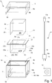
- Fig. 1 shows the packaging 1.
- the packaging 1 comprises a receptacle 3, a lid 6 and a retainer 7.
- the retainer 7 is arrangeable in the inner cavity 4 of the receptacle 3.
- the receptacle comprises an opening 5, which is closable with a lid 6.
- an electronic device 2 can be arranged in the retainer 7 .
- the electronic device may be, for example, an electrical aerosol generating device (e.g. heat-not-burn device or e-cigarette).
- the retainer 7 comprises a recess 8 in which the electronic device 2 fits at least in part.
- the lid 6 is a slip lid.
- the lid 6 comprises a support area 6a, which is arranged circumferentially on the inner surface of the sidewalls 6b of the lid 6.
- the surface normal of the support area 6a is parallel to the extent of the sidewalls 3a of the receptacle. In this way, the support area 6a rests on the upper edge 3b of the sidewalls 3a of the receptacle 3 when the packaging is closed.
- the retainer 7 is arrangeable in the inner cavity 4 of the receptacle 3.
- the retainer 7 comprises a recess 8.
- the recess 8 is shaped as a counterpart to the shape of the electronic device 2. This means, that the recess 8 is shaped to receive and hold the electronic device 2 at least in part. In part means, that the electronic device 2 may not fit completely into the recess 2 and that parts of the electronic device 2 may protrude out of the recess while other parts of the electronic device 2 are contained in the recess 8.
- a lower part 2b of the electronic device 2 can be arranged in the recess 8, while an upper part 2a of the electronic device 2 protrudes out of the recess at the top side 8a.
- the recess 8 is shaped as a mold for at least a part of the electronic device 2.
- the recess 8 is confined by walls 23a-e, leaving the top side 8a open for insertion of the electronic device.
- the five walls 23a-e comprise four side walls 23a-d and one bottom wall 23e, in case of a cuboid shape of the electronic device 2. If the electronic device 2 comprises a cuboid shape with rounded corners and edges, the walls 23a-e will be shaped as a negative of the electronic devices 2 shape with the same rounded corners and edges.
- the side walls 23a-d have a downward extent. At the top side 8a of the recess an outwardly extending flange 17 is arranged.
- the flange 17 extends in the same plane as the open top side 8a of the recess 2.
- the flange 17 extends circumferentially around the open top side 8a.
- the flange 17 extends horizontally.
- the horizontal extent of the flange 17 varies.
- the horizontal extent of the flange 17 is determined by the shape of the receptacle.
- the receptacle 3 comprises support edges 18 in the inner cavity of the receptacle.
- the support edges 18 comprise a horizontal area 18 on which the flange 17 of the retainer 7 can be rested.
- the retainer 7 is arrangeable in the inner cavity 4 of the receptacle through an opening 5 of the receptacle, wherein the retainer 7 is held in position in the inner cavity 4 by the flange 17 which rests on the support edges 18 of the receptacle.
- the walls 23a-e of the recess 8 are not in contact with the receptacle 3, when the retainer 7 is arranged in the inner cavity 4 of the receptacle 3. Only the flanges 17 of the retainer 7 are in contact with the receptacle, namely its support edges 18.
- a gap is present between the walls 23a-e of the retainer 7 arranged in the receptacle and the side walls 3a of the receptacle 3 .
- additional compartments 22 can be arranged.
- Such compartments can contain accessories for the electronic device during the first use and also during the second use of the packaging 1.
- the electronic device 2 can be fitted at least in part in the recess 8 of the retainer 7.
- the electronic device 2 comprises a charging socket 24 such as a USB-C port.
- a plug 11 a such as a USB-C plug, of the first connector 11 of the charging device 9 can be connected to the electronic device 2.
- the cable 10 may also be connectable to the connector 12 (or charger) via a connecting plug such as USB-A plug (not shown).
- the first and second connectors 11, 12 are so arranged at the respective ends 10a, 10b of the cable 10.
- the retainer 7 comprises a passage 15.
- the passage 15 is an orifice 15.
- the orifice 15 is sealed by an adhesive label 25.
- the adhesive label 25 is either arranged on the inner surface 27a or the outer surface 27b of one of the walls 23a-e.
- the adhesive label 25 comprises a flap 25a, which is non-adhesive. The flap can be grabbed by the consumer and allows the consumer to remove the adhesive label 25 more easily.
- the adhesive label 25 is larger than the orifice 15 with regard to their respective lateral extents. This means, that the adhesive label 25 completely closes the orifice 15.
- the adhesive label 25 adheres to the wall 23a-e in which the orifice 15 is located.
- the orifice 15 is aligned with the charging socket 24 of the electronic device 2. This means, that the charging socket 24 can be accessed through the orifice 15, when the electronic device 2 is arranged in the recess 8 of the retainer 7.
- the charging socket 24 is arranged on a bottom side 2c.
- the plug 11a is insertable into the electronic device in a vertical direction.
- the orifice 15 is located on the bottom wall 23e of the recess 8.
- the plug 11a and the first connector 11 are guidable through the orifice 15 in a vertical direction. By guiding the first connector 11 comprising the plug 11a through the orifice 15, the plug 11a is insertable into the charging socket 24.
- the receptacle 3 comprises an orifice 14.
- the orifice 14 is sealed by a closure wall 14a.
- the closure wall 14a is affixed to the side wall 3a of the receptacle 3 by a perforation 14b.
- the orifice 14 is arranged at a bottom part 16 of the side wall 3a.
- the orifice 14 is larger in diameter than the first connector 11. This means, that the first connector together with the thereto attached cable 10 can be routed through the orifice 14 of the receptacle 3 into the inner cavity 4 of the receptacle.
- the first connector 11 can be guided through the orifice 15 of the retainer 7 and be inserted into the charging socket of the electronic device 2 placed in the recess 8 of the retainer 7. In this way, the packaging 1 can be used as a docking station for charging the electronic device 2.
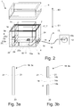
- Figure 2 shows a view of the packaging 1 with the electronic device 2 connected to the power supply system 13 with the charging device 9 during its second use.
- the electronic device 2 is arranged in the retainer 7.
- An upper part 2a of the electronic device 2 protrudes out of the recess 8 whereas a lower part 2b of the electronic device 2 is arranged in the recess 8.
- the upper part 2a and the lower part 2b are separated by the upper edge 8a of the recess 8.
- the flange 17 of the retainer 7 is rested on the support edges 18 of the receptacle 3.
- the walls 23a-e of the recess 8 are not in contact with the side walls 3a of the receptacle and the bottom wall 3c of the receptacle 3.
- the bottom wall 23e of the recess 8 is distanced to the bottom walls 3c of the receptacle 3 by a distance 28.
- the side wall 3a of the receptacle 3 and the side wall 23a of the recess 8 are distanced by a distance 29.
- the gap between the side walls 3a, 23a and the bottom walls 3c, 23e can be occupied by further compartments 22 and parts of the charging device 9.
- the orifices 14, 15 are open.
- the closure wall 14a and the adhesive label 25 (not shown here) have been removed.
- the cable 10 is routed from the first connector, which is plugged into the charging socket 24 of the electronic device 2 through the orifice 15, in the space between the bottom wall 23e of the recess 8 and the bottom wall 3c of the receptacle 3 to the orifice 14 of the receptacle 3.
- the cable 10 is routed through the orifice 14 of the receptacle 3. In this way, the cable 10 is guided from the inner cavity 4 of the receptacle 3 outside of the receptacle 3.
- the cable 10 is further routed to the power supply system 13 to which it is connected via the second connector 12.
- the orifice 14 of the receptacle 3 is arranged in a bottom part 16 of the receptacles 3 side wall 3a.
- Bottom part 16 means, that the orifice 14 is arranged at a vertical position on the side wall 3a, which lies within the height 28 of the gap between the bottom wall 23e of the recess 8 and the bottom wall 3c of the receptacle 3.
- the orifice is arranged below the bottom wall 23e of the recess 8. This means, that the gap between the bottom wall 23e of the recess 8 and the bottom wall 3c of the receptacle is accessible through the orifice 14 from the outside of the receptacle 3.
- the extraction direction E1 of the first connector 11 out of the charging socket 24 of the electronic device 2 is parallel but directly opposite to an extraction direction E2 of the electronic device 2 out of the retainer 7. In this way, the first connector 11 is disconnected from the charging socket 24 in the extraction direction E1 when the electronic device 2 is removed from the retainer 7 in the extraction direction E2.
- the distance 28 between the bottom wall 23e of the recess 8 and the bottom wall 3c of the receptacle is larger than the dimension of the first connector 11 plugged into the charging socket 24 measured parallel to the distance 28.
- Figure 3a shows a schematic view of the laminated material 19. At least the side walls 3a of the receptacle 2 consist of the laminated material 19.
- the laminated material 19 comprises a center layer 20 sandwiched between two outer layers 21.
- the center layer 20 is thicker than the respective outer layers 21.
- Figure 3b shows a schematic view of the laminated material 19 with the orifice 14.
- the orifice 14 is closed with the closure wall 14a.
- the closure wall 14a consists only of one of the outer layers 21, while the orifice 14 in the center layer 20 and the other outer layer 21 remains open.
- the closure wall 14a is connected with the outer layer 21 via the perforation 14b.
- the outer layer 21 directed towards the inner cavity of the receptacle 3 remains discontinuous at the orifice 14, whereas the other outer layer 21 comprises the closure wall 14a.
- Figure 4 shows another embodiment of the retainer 7.
- the orifice 15 is closed with a closure wall 26.
- the closure wall is connected with the bottom wall 23e via a perforation 26 a.
- the closure wall 26 may be of the same material as the bottom wall 23e.
- FIG. 5 shows another embodiment of the retainer 7.
- the retainer 7 comprises a linkage 30 at the orifice 15.
- the first connector 11 is affixable in the linkage 30. In this way, the first connector 11 remains positioned in the orifice 15 whether or not the first connector 11 is connected to the electronic device 2 (not shown here).
- the linkage is arranged at the outer surface 27b of the recess 8.
- the linkage 30 may be a clip in which the first connector 11 can be clipped in and secured in its position.
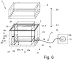
- FIG. 6 shows the packaging 1 according to another embodiment.
- the first connector 11 is an inductive connector.
- the passage 15 corresponds to the whole bottom wall 23e of the recess 8.
- the electronic device 2 is inductively coupled to the first connector 11 through the passage 15.
- the first connector is arranged in the gap between the bottom wall 23e of the recess 8 and the bottom wall 3c of the receptacle.
- the cable 10 is disconnectable from the first and/or second connector 11, 12 at the cable ends 10a, 10b.
- the first and the second connector 11, 12 can be larger in their smallest diameter than the orifice 14 of the receptacle 3.
- the cable 10 can be disconnected from the first and/or second connector 11, 12 and be routed through the orifice 14 of the receptacle 3. After that the cable 10 can be reconnected to the first and/or second connector 11, 12 to enable charging of the electronic device 2.
Landscapes
- Engineering & Computer Science (AREA)
- Mechanical Engineering (AREA)
- Packaging Of Annular Or Rod-Shaped Articles, Wearing Apparel, Cassettes, Or The Like (AREA)
Abstract
The invention relates to a packaging (1) for an electronic device (2) and charging device (9) comprising a cable (10) and a first and second connector (11, 12), the packaging comprising a receptacle (3) having an inner cavity (4), in which the electronic device (2) is arrangeable, and an opening (5), through which the electronic device (2) is removable and insertable into the inner cavity (4) of the receptacle (3), a lid (6), with which the opening (5) of the receptacle (3) is closable, a retainer (7), comprising a counterpart recess (8) for the electronic device (2) for receiving the electronic device (2) at least in part, wherein the retainer (7) with the electronic device (2) is placeable in the inner cavity (4) of the receptacle (3), wherein the first and second connectors are arrangeable at respective ends (10a, 10b) of the cable (10) and the electronic device (2) is connectable with the cable (10) via the first connector (11) and the cable (10) is connectable with a power supply system (13) via the second connector (12), wherein an orifice (14) of the receptacle (3) through which the cable (10) is passable from the inner cavity (4) to the outside of the receptacle (3) and a passage (15) of the retainer (7) through which the electronic device (2) is connectable with the first connector (11) of the charging device (9).
Description
- The present invention relates to a packaging for an electronic device and charging device.
- Manufacturers of electronic devices often produce elaborate packaging, in which the electronic devices are shipped and/or sold to the consumer. Typically, such packaging is not subjected to further use after the consumer unpackaged the newly bought electronic device. After unpackaging the electronic device, the packaging is typically thrown away. In view of sustainability and the expenses, necessary for development and production of such packaging, such one-time usage is undesirable.
- It is therefore the objective of the invention to provide a packaging for an electronic device, which enables a second use of the packaging after serving as a packaging of the electronic device.
- This objective is reached by a packaging for an electronic device and for a charging device comprising a cable and a first and second connector arranged such that the electronic device is connectable with the cable via the first connector and the cable is connectable with a power supply system via the second connector, the packaging comprising a receptacle having an inner cavity, in which the electronic device is arrangeable, and an opening, through which the electronic device is removable and insertable into the inner cavity of the receptacle, a lid, with which the opening of the receptacle is closable, a retainer, comprising a counterpart recess for the electronic device for receiving the electronic device at least in part, wherein the retainer with the electronic device is placeable in the inner cavity of the receptacle, wherein an orifice of the receptacle through which the cable of the charging device is passable from the inner cavity to the outside of the receptacle and a passage of the retainer through which the electronic device is connectable with the first connector of the charging device.
- The term packaging refers to a packaging of an electronic device in which the electronic device packaged at the production site and in which it is sold to the customer. By holding the electronic device tightly in the packaging, the electronic device arrives without damage at the consumer. The wrapping of the electronic device until arrival at the customer denotes the first use or primary purpose of the packaging.
- However the invention enables a second use (secondary purpose) of the packaging after its first use. With the orifice in the receptacle the cable can be routed from a power supply system, e.g. a wall plug, into the inner cavity of the receptacle. With the passage of the retainer, the cable, which is routed through the orifice, can be connected via its first connector to the electronic device, which is arranged in the retainer. In this way an arrangement is obtainable in which the electronic device is arranged in the retainer of the receptacle, the electronic device is connected with the cable via the first connector through the passage of the retainer, the cable is routed through the orifice of the receptacle from the inner cavity of the receptacle to the outside of the receptacle where the cable is connected with a power supply system via the second connector. In this way it is possible to charge the electronic device while it is situated in the packaging. This enables a second use of the packaging as a docking station for charging the electronic device. In this way, the packaging is further usable as a docking station for charging the electronic device after its first use as a packaging for secure transport of the electronic device. With this secondary purpose the packaging does not need to be discarded after unwrapping the electronic device after purchase. In terms of sustainability, this is highly desirable. Also the customer obtains the benefit of an additional and free docking station directly provided with the electronic device.
- According to another embodiment the orifice is located at a bottom part of a side wall of the receptacle. By locating the orifice at a bottom part of the side wall, the cable routed through the orifice will leave the receptacle near surface on which the packaging is positioned. This enables the cable to be tidily routable to a power supply system, for example a wall plug. The overall optical impression of the packaging with the cable connected to a power supply system improved, as the cable determines the overall optical impression less. Preferably, the orifice is located at back side wall of the receptacle. This will further improve the overall optical impression of the packaging with the cable connected to a power supply system, as the packaging itself hides the cable.
- According to another embodiment the orifice is sealed by a closure wall, which is connected to the receptacle side wall via a prescored perforation. Preferably, the closure wall is detachable from the receptacle sidewall by separating the closure wall from the receptacle side wall at the perforation. With the closure wall the orifice is sealed during the first use of the packaging. After the customer unpackaged the electronic device from the packaging, i.e. when the primary purpose of the packaging is fulfilled, the customer can then separate the closure wall from the receptacle side wall at the prescored perforation. By doing so, the closure wall is removed from the receptacle side wall, which opens the orifice. The cable can then be routed through the orifice from the inner cavity of the receptacle to the outside of the receptacle where it is connectable to a power supply system via its second connector. With the closure wall, the orifice, which is only necessary for the secondary purpose but not for the primary, remains closed during the use of the packaging according to its first purpose. Due to the prescored perforation the closure wall can easily be separated from the receptacle by the customer. In this way the packaging can be transformed from fully serving its primary purpose to fully serving its secondary purpose in a very easy and convenient way.
- According to another embodiment the retainer comprises an outwardly extending flange resting on support edges of receptacle. With the flange the retainer can be easily arranged in the inner cavity of the receptacle. Preferably, only the flange of the retainer is in contact with the receptacle, wherein all other parts of the retainer are suspended in the air of the inner cavity of the receptacle. In this way the electronic device is shielded from any shocks during the first use of the packaging. For the second use this arrangement is also advantageous. The flange just rests on the support edges. This implies that the retainer can easily be lifted upwards and be thereby removed from the receptacle. This enables the access to the inner cavity of the receptacle, e.g. for routing the cable through the orifice and/or connect the first connector of the cable to the electronic device via the passage of the retainer.
- According to another embodiment the receptacle comprises a laminated material. Preferably, the receptacle walls consist of the laminated material. Laminated material consists of at least two individual material layers, which are affixed to each other with one of their laminar surfaces. The laminated material comprises the advantage of being able to combine advantageous properties of different materials. For example, a stiff but optically not appealing material could be covered with an optically appealing but very soft material and thus obtaining a laminated material which is stiff and optically appealing. Also due to the affixation of the individual material layer to each other, the stiffness of the laminated material may be improved in comparison to the stiffness of the individual material layers.
- According to another embodiment the laminated material comprises a center layer out of cardboard. Preferably, the center layer is covered on both surfaces with a respective outermost layer. In this way, preferably a laminated material consisting of three individual layers is formed. Cardboard is a very cheap material with broad availability which still provides high stiffness. In this way a robust packaging can be manufactured at low manufacturing costs.
- According to another embodiment the laminated material comprises two paper layers each laminated on one of the two sides of the center layer. This means that the two paper layers denote the outermost layers, which are affixed to the two surfaces of the center layer. The paper layers may consist of normal paper, coated paper or any other suitable type of paper. Preferably the paper comprises prints, writing and/or logos. In this way the packaging can be easily equipped with embellishments.
- According to another embodiment the orifice of the receptacle runs through all layers of laminated material and the material of the outermost layer of the laminated material forms the closure wall and is connected only thereto. In other words, each individual layer of the laminated material comprises a hole, wherein the holes are positioned congruent on each other and together form the orifice. The closure wall consists only of the material of the outermost material layer arranged towards the outside of the receptacle. The closure is attached via the prescored perforation only to the outermost material layer arranged towards the outside of the receptacle. Therefore, the closure wall can be removed much more easily as is has to be separated only from one of the layer of the laminated material and not from all layers. Much less force for separating the closure wall from the one outermost layer at the perforation will be necessary as in this embodiment the webs, which denote the part of the perforation which actually connects the closure wall with the surrounding material of the receptacle, are much thinner because they only consist of one of the material layers of the laminated material. As a result, the consumer can remove the closure wall much easier which makes putting the packaging to its second use much more convenient.
- According to another embodiment a gap is present between the counterpart recess and the receptacle. In other words, the counterpart recess is not in contact with the receptacle. As discussed before, the retainer is only in contact with the receptacle at the flanges. The gap not only provide shock protection of the electronic device during the first use of the packaging. The gap furthermore enables an arrangement of at least a part of the cable and the first connector between the counterpart recess and the receptacle. This also means that unneeded length of the cable, e.g. when the wall plug is in short distance to the packaging, can be stored inside the packaging. This leads to an effective length adjustability of the cable.
- According to another embodiment the packaging comprises further compartments for storing accessories. These compartments are preferably arranged in the gap between the counterpart recess and the receptacle. This is a convenient way to store accessories for the electronic device not only during the first use of the packaging but also during the second use. Often consumers loose accessories belonging to their electronic devices or do not find them anymore because there is no specific easy to find place to store such accessories. If the packaging is put to its second use as a docking station, the accessories can be stored in this docking station. This means the consumer has all accessories perfectly stored in an easy to memorize place.
- According to another embodiment the passage consists of a passage area of recessed walls, which are permeable for an electromagnetic field. The recessed walls are the side walls of the counterpart recess. The recessed walls extend downwardly from the flange into the inner cavity of the receptacle thereby forming the counterpart recess. At least in the passage area, the recessed walls are permeable for an electromagnetic field. In this embodiment the first connector preferably is an inductive connector, which connects the cable with the electronic device inductively. In this way, the consumer only needs to put the electronic device into the counterpart recess of the retainer. The electronic device is thereby automatically positioned correctly to connect inductively to the cable, so that the electronic device is automatically charged when it is placed in the counterpart recess.
- According to another embodiment the passage consists of a second orifice in a wall of the recess through which the first connector is connectable with the electronic device. In this embodiment the first connector comprises a plug, which matches a charging socket of the electronic device. When the electronic device is arranged in the counterpart recess, the plug can be arranged in the charging socket through the second orifice.
- In this embodiment to charge the electronic device in the packaging according to its secondary purpose the consumer preferably removes the retainer from the receptacle, puts the electronic device into the counterpart recess of the retainer, takes the first connector from the receptacle and connects it to the electronic device by inserting the plug of the first connector through the second orifice into the charging socket of the electronic device and then puts the retainer with the electronic device back into the receptacle. If desired, the packaging can then be closed by putting the lid onto the receptacle.
- Preferably, the counterpart recess comprises a linkage on the surface facing the receptacle walls, wherein the linkage is arranged at the second orifice. Preferably, the first connector is affixable in the linkage. Preferably, the first connector is affixed in the linkage in the very position the first connector comprising the plug occupies when being connected to the charging socket of the electronic device. This means, that the first connector is arranged in the in the second orifice, wherein a cable facing side of the first connector is arranged at the outer surface of the recessed walls and the plug, arranged on the averted side of the first connector, is arranged at the inner surface of the recessed walls. The outer surface of the recessed walls faces the receptacle, wherein the inner surface of the recessed walls face the electronic device. In this way, the first connector can be affixed in the correct position. The consumer only needs to place the electronic device in the counterpart recess and thereby automatically connects the electronic device with the cable via the first connector.
- In this embodiment the consumer does not need to take retainer out of the receptacle for connecting the electronic device with the cable. By putting the electronic device into the counterpart recess, the plug of the first connector, which is held in place by the linkage, is automatically plugged into the charging socket of the electronic device.
- According to another embodiment the position of the second orifice in the wall of the recess aligns with the position of a charging socket of the electronic device when the device is received in the counterpart recess. With this alignment the first connector comprising a plug can be easily plugged into the charging socket of the electronic device, which is arranged in the counterpart recess, wherein the first connector with the plug is routed from the outer surface of the recessed walls through the second orifice into the charging socket.
- According to another embodiment the second orifice of the retainer is sealed by an adhesive label or is by a closure wall, which is connected at least one of the recessed walls via a prescored perforation. This closes the second orifice similar to the closure wall of the first orifice. The second orifice is in this way closed during the first use of the packaging and can be opened by the consumer easily for the secondary purpose of the packaging. With a sealed second orifice the protective properties of the packaging during the first use are improved compared to a permanently open second orifice. The adhesive label can be removed easily by the consumer. In alternative to the adhesive label, a closure wall can be arranged in the second orifice to seal it. Preferably, the closure wall is connected to at least one of the recessed walls via a prescored perforation. The consumer has to break the webs of the perforation, which connect the recessed walls with the closure wall. Preferably, the perforation comprising the webs are designed to break easily, when the customer applies a force, but withstand the potential shocks, which might occur during the first use of the packaging as a protection of the electronic device. The adhesive label is preferably made of plastic. Preferably, the adhesive label is larger than the second orifice, so it can cover the second orifice completely and also covers a part of the recessed wall directly surrounding the second orifice. Preferably, the adhesive label comprises a non-adhesive flap at its outer edge, which the consumer can grab easily and therefore remove the adhesive label more conveniently. The adhesive label can be applied to the recessed walls on their outer or inner surface. The closure wall preferably consists of the same material as the retainer. It is also possible to use a closure wall with an additional adhesive label. This increases the stability of the perforation during the first use of the packaging and prevents an unintended separation of the closure wall from the recessed walls.
- According to another embodiment the packaging comprises a cuboid shape and the first orifice is located at a lower corner of one of the side walls and the second orifice is located at the bottom side wall of the retainer. The cuboid shape of the packaging is most advantageous for effective stacking of multiple packaging. The lower corner is a corner of a side wall of the receptacle, which is located next to the base area of the packaging. In contrast to that an upper corner of a side wall is located next to the opening of the receptacle, wherein the opening is located on the opposite side of the base area of the packaging. Located at a lower corner means, that the second orifice is either located directly at this corner or within a small distance to the corner. Preferably, the second orifice is located within a small distance to the corner, as this will increase the stability of the packaging. Preferably, the small distance is smaller than the largest dimension of the closure wall. The second orifice being located at the bottom side wall of the retainer means, that the second orifice is located on a part of the recessed walls which is parallel to the base area of the receptacle. This arrangement is preferred as the direction in which the plug of the first connector is inserted into or removed from the charging socket of the electronic device is in this case parallel to an insertion/removal direction of the electronic device into or from the retainer. This ensures, that the charging socket and the first connector are not damaged when the consumer removes the electronic device from the retainer and forgets to unplug the first connector before, as by removing the electronic device from the retainer, the plug of the first connector is automatically removed from the charging socket due to the parallel removal direction.
- Further advantages, objectives and features of the present invention will be described, by way of example only, in the following description with reference to the appended figures. In the figures, like components in different embodiments can exhibit the same reference symbols.
- The figures show:
- Fig. 1
- a general view of all the components of the
packaging 1; - Fig. 2
- a view of the
packaging 1 with theelectronic device 2 connected to thepower supply system 13 with the chargingdevice 9; - Fig. 3a
- a schematic view of the laminated material 19;
- Fig. 3b
- a schematic view of the laminated material 19 with the
orifice 14; - Fig. 4
- a detailed view of another embodiment of the
retainer 7; - Fig. 5
- a detailed view of another embodiment of the
retainer 7; - Fig. 6
- a view of the
packaging 1 according to another embodiment. -
Fig. 1 shows thepackaging 1. Thepackaging 1 comprises areceptacle 3, alid 6 and aretainer 7. Theretainer 7 is arrangeable in theinner cavity 4 of thereceptacle 3. The receptacle comprises anopening 5, which is closable with alid 6. In theretainer 7 anelectronic device 2 can be arranged. The electronic device may be, for example, an electrical aerosol generating device (e.g. heat-not-burn device or e-cigarette). For this purpose, theretainer 7 comprises arecess 8 in which theelectronic device 2 fits at least in part. Thelid 6 is a slip lid. Thelid 6 comprises asupport area 6a, which is arranged circumferentially on the inner surface of thesidewalls 6b of thelid 6. The surface normal of thesupport area 6a is parallel to the extent of thesidewalls 3a of the receptacle. In this way, thesupport area 6a rests on theupper edge 3b of thesidewalls 3a of thereceptacle 3 when the packaging is closed. - As already mentioned, the
retainer 7 is arrangeable in theinner cavity 4 of thereceptacle 3. Theretainer 7 comprises arecess 8. Therecess 8 is shaped as a counterpart to the shape of theelectronic device 2. This means, that therecess 8 is shaped to receive and hold theelectronic device 2 at least in part. In part means, that theelectronic device 2 may not fit completely into therecess 2 and that parts of theelectronic device 2 may protrude out of the recess while other parts of theelectronic device 2 are contained in therecess 8. In the herein described embodiment alower part 2b of theelectronic device 2 can be arranged in therecess 8, while anupper part 2a of theelectronic device 2 protrudes out of the recess at thetop side 8a. In other words, therecess 8 is shaped as a mold for at least a part of theelectronic device 2. Therecess 8 is confined bywalls 23a-e, leaving thetop side 8a open for insertion of the electronic device. The fivewalls 23a-e comprise fourside walls 23a-d and onebottom wall 23e, in case of a cuboid shape of theelectronic device 2. If theelectronic device 2 comprises a cuboid shape with rounded corners and edges, thewalls 23a-e will be shaped as a negative of theelectronic devices 2 shape with the same rounded corners and edges. Theside walls 23a-d have a downward extent. At thetop side 8a of the recess an outwardly extendingflange 17 is arranged. Theflange 17 extends in the same plane as the opentop side 8a of therecess 2. Theflange 17 extends circumferentially around the opentop side 8a. Theflange 17 extends horizontally. The horizontal extent of theflange 17 varies. The horizontal extent of theflange 17 is determined by the shape of the receptacle. - The
receptacle 3 comprises support edges 18 in the inner cavity of the receptacle. The support edges 18 comprise ahorizontal area 18 on which theflange 17 of theretainer 7 can be rested. Theretainer 7 is arrangeable in theinner cavity 4 of the receptacle through anopening 5 of the receptacle, wherein theretainer 7 is held in position in theinner cavity 4 by theflange 17 which rests on the support edges 18 of the receptacle. Thewalls 23a-e of therecess 8 are not in contact with thereceptacle 3, when theretainer 7 is arranged in theinner cavity 4 of thereceptacle 3. Only theflanges 17 of theretainer 7 are in contact with the receptacle, namely its support edges 18. Between thewalls 23a-e of theretainer 7 arranged in the receptacle and theside walls 3a of thereceptacle 3 a gap is present. In this gapadditional compartments 22 can be arranged. Such compartments can contain accessories for the electronic device during the first use and also during the second use of thepackaging 1. - The
electronic device 2 can be fitted at least in part in therecess 8 of theretainer 7. Theelectronic device 2 comprises a chargingsocket 24 such as a USB-C port. In this charging socket 24 aplug 11 a, such as a USB-C plug, of thefirst connector 11 of thecharging device 9 can be connected to theelectronic device 2. By connecting thesecond connector 12, including a charger in this example, to apower supply system 13, theelectronic device 2 is chargeable. Thecable 10 may also be connectable to the connector 12 (or charger) via a connecting plug such as USB-A plug (not shown). The first andsecond connectors cable 10. - The
retainer 7 comprises apassage 15. In this embodiment, thepassage 15 is anorifice 15. Theorifice 15 is sealed by anadhesive label 25. Theadhesive label 25 is either arranged on theinner surface 27a or theouter surface 27b of one of thewalls 23a-e. Theadhesive label 25 comprises aflap 25a, which is non-adhesive. The flap can be grabbed by the consumer and allows the consumer to remove theadhesive label 25 more easily. Theadhesive label 25 is larger than theorifice 15 with regard to their respective lateral extents. This means, that theadhesive label 25 completely closes theorifice 15. Theadhesive label 25 adheres to thewall 23a-e in which theorifice 15 is located. - The
orifice 15 is aligned with the chargingsocket 24 of theelectronic device 2. This means, that the chargingsocket 24 can be accessed through theorifice 15, when theelectronic device 2 is arranged in therecess 8 of theretainer 7. The chargingsocket 24 is arranged on abottom side 2c. Theplug 11a is insertable into the electronic device in a vertical direction. Theorifice 15 is located on thebottom wall 23e of therecess 8. Theplug 11a and thefirst connector 11 are guidable through theorifice 15 in a vertical direction. By guiding thefirst connector 11 comprising theplug 11a through theorifice 15, theplug 11a is insertable into the chargingsocket 24. - The
receptacle 3 comprises anorifice 14. Theorifice 14 is sealed by aclosure wall 14a. Theclosure wall 14a is affixed to theside wall 3a of thereceptacle 3 by aperforation 14b. When putting the packaging to its second use, the consumer removes theclosure wall 14a at theperforation 14b. Theorifice 14 is arranged at abottom part 16 of theside wall 3a. Theorifice 14 is larger in diameter than thefirst connector 11. This means, that the first connector together with the thereto attachedcable 10 can be routed through theorifice 14 of thereceptacle 3 into theinner cavity 4 of the receptacle. From there, thefirst connector 11 can be guided through theorifice 15 of theretainer 7 and be inserted into the charging socket of theelectronic device 2 placed in therecess 8 of theretainer 7. In this way, thepackaging 1 can be used as a docking station for charging theelectronic device 2. -
Figure 2 shows a view of thepackaging 1 with theelectronic device 2 connected to thepower supply system 13 with the chargingdevice 9 during its second use. Theelectronic device 2 is arranged in theretainer 7. Anupper part 2a of theelectronic device 2 protrudes out of therecess 8 whereas alower part 2b of theelectronic device 2 is arranged in therecess 8. Theupper part 2a and thelower part 2b are separated by theupper edge 8a of therecess 8. Theflange 17 of theretainer 7 is rested on the support edges 18 of thereceptacle 3. Thewalls 23a-e of therecess 8 are not in contact with theside walls 3a of the receptacle and thebottom wall 3c of thereceptacle 3. Thebottom wall 23e of therecess 8 is distanced to thebottom walls 3c of thereceptacle 3 by adistance 28. Theside wall 3a of thereceptacle 3 and theside wall 23a of therecess 8 are distanced by a distance 29. The gap between theside walls bottom walls further compartments 22 and parts of thecharging device 9. - The
orifices closure wall 14a and the adhesive label 25 (not shown here) have been removed. Thecable 10 is routed from the first connector, which is plugged into the chargingsocket 24 of theelectronic device 2 through theorifice 15, in the space between thebottom wall 23e of therecess 8 and thebottom wall 3c of thereceptacle 3 to theorifice 14 of thereceptacle 3. Thecable 10 is routed through theorifice 14 of thereceptacle 3. In this way, thecable 10 is guided from theinner cavity 4 of thereceptacle 3 outside of thereceptacle 3. Thecable 10 is further routed to thepower supply system 13 to which it is connected via thesecond connector 12. - The
orifice 14 of thereceptacle 3 is arranged in abottom part 16 of thereceptacles 3side wall 3a.Bottom part 16 means, that theorifice 14 is arranged at a vertical position on theside wall 3a, which lies within theheight 28 of the gap between thebottom wall 23e of therecess 8 and thebottom wall 3c of thereceptacle 3. With other words, the orifice is arranged below thebottom wall 23e of therecess 8. This means, that the gap between thebottom wall 23e of therecess 8 and thebottom wall 3c of the receptacle is accessible through theorifice 14 from the outside of thereceptacle 3. The extraction direction E1 of thefirst connector 11 out of the chargingsocket 24 of theelectronic device 2 is parallel but directly opposite to an extraction direction E2 of theelectronic device 2 out of theretainer 7. In this way, thefirst connector 11 is disconnected from the chargingsocket 24 in the extraction direction E1 when theelectronic device 2 is removed from theretainer 7 in the extraction direction E2. - The
distance 28 between thebottom wall 23e of therecess 8 and thebottom wall 3c of the receptacle is larger than the dimension of thefirst connector 11 plugged into the chargingsocket 24 measured parallel to thedistance 28. -
Figure 3a shows a schematic view of the laminated material 19. At least theside walls 3a of thereceptacle 2 consist of the laminated material 19. The laminated material 19 comprises acenter layer 20 sandwiched between twoouter layers 21. Thecenter layer 20 is thicker than the respectiveouter layers 21. -
Figure 3b shows a schematic view of the laminated material 19 with theorifice 14. Theorifice 14 is closed with theclosure wall 14a. Theclosure wall 14a consists only of one of theouter layers 21, while theorifice 14 in thecenter layer 20 and the otherouter layer 21 remains open. Theclosure wall 14a is connected with theouter layer 21 via theperforation 14b. Theouter layer 21 directed towards the inner cavity of thereceptacle 3 remains discontinuous at theorifice 14, whereas the otherouter layer 21 comprises theclosure wall 14a. -
Figure 4 shows another embodiment of theretainer 7. Theorifice 15 is closed with a closure wall 26. The closure wall is connected with thebottom wall 23e via aperforation 26 a. The closure wall 26 may be of the same material as thebottom wall 23e. -
Figure 5 shows another embodiment of theretainer 7. Theretainer 7 comprises alinkage 30 at theorifice 15. Thefirst connector 11 is affixable in thelinkage 30. In this way, thefirst connector 11 remains positioned in theorifice 15 whether or not thefirst connector 11 is connected to the electronic device 2 (not shown here). The linkage is arranged at theouter surface 27b of therecess 8. Thelinkage 30 may be a clip in which thefirst connector 11 can be clipped in and secured in its position. -
Figure 6 shows thepackaging 1 according to another embodiment. Thefirst connector 11 is an inductive connector. Thepassage 15 corresponds to the wholebottom wall 23e of therecess 8. Theelectronic device 2 is inductively coupled to thefirst connector 11 through thepassage 15. The first connector is arranged in the gap between thebottom wall 23e of therecess 8 and thebottom wall 3c of the receptacle. Preferably, thecable 10 is disconnectable from the first and/orsecond connector second connector orifice 14 of thereceptacle 3. Thecable 10 can be disconnected from the first and/orsecond connector orifice 14 of thereceptacle 3. After that thecable 10 can be reconnected to the first and/orsecond connector electronic device 2. - The applicant reserves his right to claim all features disclosed in the application document as being an essential feature of the invention, as long as they are new, individually or in combination, in view of the prior art. Furthermore, it is noted that in the figures features are described, which can be advantageous individually. Someone skilled in the art will directly recognize that a specific feature being disclosed in a figure can be advantageous also without the adoption of further features from this figure. Furthermore, someone skilled in the art will recognize that advantages can evolve from a combination of diverse features being disclosed in one or various figures.
-
- 1
- packaging
- 2
- electronic device
- 2a
- upper part
- 2b
- lower part
- 2c
- bottom side
- 3
- receptacle
- 3a
- side wall
- 3b
- upper edge
- 3c
- bottom wall
- 4
- inner cavity
- 5
- opening
- 6
- lid
- 6a
- support area
- 6b
- sidewalls
- 7
- retainer
- 8
- recess
- 8a
- top side
- 9
- charging device
- 10
- cable
- 10a,b
- ends of cable
- 11
- first connector
- 11a
- plug
- 12
- second connector
- 13
- power supply system
- 14
- orifice
- 14a
- closure wall
- 14b
- prescored perforation
- 15
- passage, orifice
- 16
- bottom part
- 17
- flange
- 18
- support edges, horizontal area
- 19
- laminated material
- 20
- center layer
- 21
- layer
- 22
- compartments
- 23a-e
- walls
- 23e
- bottom wall
- 24
- charging socket
- 25
- adhesive label
- 25a
- flap
- 26
- closure wall
- 26a
- prescored perforation
- 27a
- inner surface
- 27b
- outer surface
- 28
- distance, height
- 29
- distance
- 30
- linkage
- E1
- extraction direction
- E2
- extraction direction
Claims (15)
- Packaging (1) for an electronic device (2) and charging device (9) comprising a cable (10) and a first and second connector (11, 12) arranged such that the electronic device (2) is connectable with the cable (10) via the first connector (11) and the cable (10) is connectable with a power supply system (13) via the second connector (12), the packaging (1) comprising a receptacle (3) having an inner cavity (4), in which the electronic device (2) is arrangeable, and an opening (5), through which the electronic device (2) is removable and insertable into the inner cavity (4) of the receptacle (3), a lid (6), with which the opening (5) of the receptacle (3) is closable, a retainer (7), comprising a counterpart recess (8) for the electronic device (2) for receiving the electronic device (2) at least in part, wherein the retainer (7) with the electronic device (2) is placeable in the inner cavity (4) of the receptacle (3),
characterized by
an orifice (14) of the receptacle (3) through which the cable (10) of the charging device (9) is passable from the inner cavity (4) to the outside of the receptacle (3) and a passage (15) of the retainer (7) through which the electronic device (2) is connectable with the first connector (11) of the charging device (9). - Packaging (1) according to claim 1,
characterized in that,
the orifice (14) is located at a bottom part (16) of a side wall (3a) of the receptacle (3). - Packaging (1) according to claim 1 or 2,
characterized in that
the orifice (14) is sealed by a closure wall (14a), which is connected to the receptacle side wall (3a) via a prescored perforation (14b). - Packaging (1) according to at least one of the preceding claims,
characterized in that
the retainer (7) comprises an outwardly extending flange (17) resting on support edges (18) of receptacle (7) - Packaging (1) according to at least one of the preceding claims,
characterized in that
the receptacle comprises a laminated material (19). - Packaging (1) according to at least one of the preceding claims,
characterized in that
the laminated material (19) comprises a center layer (20) out of cardboard. - Packaging (1) according to at least one of the preceding claims,
characterized in that
the laminated material (19) comprises two paper layers (21) each laminated on one of the two sides of the center layer (20). - Packaging (1) according to at least one of the preceding claims,
characterized in that
the orifice (14) of the receptacle runs through all layers of laminated material (19) and the material of the outermost layer (21) of the laminated material (19) forms the closure wall (14a) and is connected only thereto. - Packaging (1) according to at least one of the preceding claims,
characterized in that
a gap is present between the counterpart recess (8) and the receptacle. - Packaging (1) according to at least one of the preceding claims,
characterized in that
the packaging (1) comprises further compartments (22) for storing accessories. - Packaging (1) according to at least one of the preceding claims,
characterized in that
the passage (15) consists of a passage area of recessed walls (23a-e), which are permeable for an electromagnetic field. - Packaging (1) according to at least one of the claims 1-10,
characterized in that
the passage (15) consists of a second orifice (15) in a wall (23a-e) of the recess (8) through which the first connector (11) is connectable with the electronic device (2). - Packaging (1) according to claim 12,
characterized in that,
the position of the second orifice (15) in the wall (23a-e) of the recess (8) aligns with the position of a charging socket (24) of the electronic device (2) when the device is received in the counterpart recess (8). - Packaging (1) according to claim 12 or 13,
characterized in that
the second orifice (15) of the retainer (7) is sealed by an adhesive label (25) or is by a closure wall (26), which is connected to at least one of the recessed walls (23a-e) via a prescored perforation (26a). - Packaging (1) according to claim 12, 13 or 14,
characterized in that
the packaging (1) comprises a cuboid shape and the first orifice (14) is located at a lower corner of one of the side walls (3a) and the second orifice (15) is located at the bottom wall (23e) of the retainer.
Priority Applications (1)
| Application Number | Priority Date | Filing Date | Title |
|---|---|---|---|
| EP19209158.5A EP3822188A1 (en) | 2019-11-14 | 2019-11-14 | Packaging for an electronic device |
Applications Claiming Priority (1)
| Application Number | Priority Date | Filing Date | Title |
|---|---|---|---|
| EP19209158.5A EP3822188A1 (en) | 2019-11-14 | 2019-11-14 | Packaging for an electronic device |
Publications (1)
| Publication Number | Publication Date |
|---|---|
| EP3822188A1 true EP3822188A1 (en) | 2021-05-19 |
Family
ID=68581596
Family Applications (1)
| Application Number | Title | Priority Date | Filing Date |
|---|---|---|---|
| EP19209158.5A Withdrawn EP3822188A1 (en) | 2019-11-14 | 2019-11-14 | Packaging for an electronic device |
Country Status (1)
| Country | Link |
|---|---|
| EP (1) | EP3822188A1 (en) |
Citations (4)
| Publication number | Priority date | Publication date | Assignee | Title |
|---|---|---|---|---|
| EP1174349A1 (en) * | 2000-07-06 | 2002-01-23 | Sony Computer Entertainment Inc. | Packing box as well as methods for the manufacture and use of the box and reading information thereon |
| JP2006008191A (en) * | 2004-06-25 | 2006-01-12 | Funai Electric Co Ltd | Packaging material for electronic device, and method for changing specification of electronic device |
| US20120153785A1 (en) * | 2010-12-17 | 2012-06-21 | Lai Chen-Ju | Package structure |
| US20180249071A1 (en) * | 2015-10-01 | 2018-08-30 | Panasonic Intellectual Property Management Co., Ltd. | Surveillance camera packing member |
-
2019
- 2019-11-14 EP EP19209158.5A patent/EP3822188A1/en not_active Withdrawn
Patent Citations (4)
| Publication number | Priority date | Publication date | Assignee | Title |
|---|---|---|---|---|
| EP1174349A1 (en) * | 2000-07-06 | 2002-01-23 | Sony Computer Entertainment Inc. | Packing box as well as methods for the manufacture and use of the box and reading information thereon |
| JP2006008191A (en) * | 2004-06-25 | 2006-01-12 | Funai Electric Co Ltd | Packaging material for electronic device, and method for changing specification of electronic device |
| US20120153785A1 (en) * | 2010-12-17 | 2012-06-21 | Lai Chen-Ju | Package structure |
| US20180249071A1 (en) * | 2015-10-01 | 2018-08-30 | Panasonic Intellectual Property Management Co., Ltd. | Surveillance camera packing member |
Similar Documents
| Publication | Publication Date | Title |
|---|---|---|
| EP2531413B1 (en) | A product package utilizing an information indicator held in a product tray | |
| US20150001238A1 (en) | Tissue Dispenser With Integral Waste Receptacle | |
| CN108349644A (en) | packaging for consumer goods | |
| CN210708328U (en) | Corrugated case convenient to fold | |
| CN211309242U (en) | Electronic product packaging box | |
| CN204548939U (en) | A kind of packing box of electronic product | |
| CN111164018A (en) | Package (I) | |
| CN207450506U (en) | A kind of low-temperature milk packaging | |
| CN108124439A (en) | Packaging element | |
| JP6363364B2 (en) | Tissue paper storage container | |
| CN211418021U (en) | Tea packing box | |
| CN221214955U (en) | Packing box | |
| CN205010735U (en) | Package displaying box | |
| CN218490403U (en) | Exempt from to open packing carton that lid placed power cord | |
| CN108750321A (en) | Packing carton that charger was accomodate suitable for multiple specification | |
| CN218949805U (en) | Packing box | |
| CN218506553U (en) | Package gift box convenient for display | |
| CN220501327U (en) | Packing box | |
| JP3188596U (en) | A tissue box and a combination of tissue boxes. | |
| CN219566157U (en) | Packing box buffer liner with supporting and positioning structure | |
| KR200359459Y1 (en) | A packing case assembly | |
| CN219278188U (en) | Lining monomer and combined plastic-absorbing lining | |
| CN213949238U (en) | Lining for red wine bottle package | |
| CN210192154U (en) | Packing carton for nianng zhan chinese yam | |
| CN113473872B (en) | Smoking article storage box |
Legal Events
| Date | Code | Title | Description |
|---|---|---|---|
| PUAI | Public reference made under article 153(3) epc to a published international application that has entered the european phase |
Free format text: ORIGINAL CODE: 0009012 |
|
| STAA | Information on the status of an ep patent application or granted ep patent |
Free format text: STATUS: THE APPLICATION HAS BEEN PUBLISHED |
|
| AK | Designated contracting states |
Kind code of ref document: A1 Designated state(s): AL AT BE BG CH CY CZ DE DK EE ES FI FR GB GR HR HU IE IS IT LI LT LU LV MC MK MT NL NO PL PT RO RS SE SI SK SM TR |
|
| STAA | Information on the status of an ep patent application or granted ep patent |
Free format text: STATUS: THE APPLICATION IS DEEMED TO BE WITHDRAWN |
|
| 18D | Application deemed to be withdrawn |
Effective date: 20211120 |