EP3822104A1 - Handling system for a manual retractable roof - Google Patents
Handling system for a manual retractable roof Download PDFInfo
- Publication number
- EP3822104A1 EP3822104A1 EP20208064.4A EP20208064A EP3822104A1 EP 3822104 A1 EP3822104 A1 EP 3822104A1 EP 20208064 A EP20208064 A EP 20208064A EP 3822104 A1 EP3822104 A1 EP 3822104A1
- Authority
- EP
- European Patent Office
- Prior art keywords
- handle
- retractable roof
- rotation axis
- rotation
- around
- Prior art date
- Legal status (The legal status is an assumption and is not a legal conclusion. Google has not performed a legal analysis and makes no representation as to the accuracy of the status listed.)
- Granted
Links
Images



Classifications
-
- B—PERFORMING OPERATIONS; TRANSPORTING
- B60—VEHICLES IN GENERAL
- B60J—WINDOWS, WINDSCREENS, NON-FIXED ROOFS, DOORS, OR SIMILAR DEVICES FOR VEHICLES; REMOVABLE EXTERNAL PROTECTIVE COVERINGS SPECIALLY ADAPTED FOR VEHICLES
- B60J7/00—Non-fixed roofs; Roofs with movable panels, e.g. rotary sunroofs
- B60J7/185—Locking arrangements
- B60J7/19—Locking arrangements for rigid panels
-
- B—PERFORMING OPERATIONS; TRANSPORTING
- B60—VEHICLES IN GENERAL
- B60J—WINDOWS, WINDSCREENS, NON-FIXED ROOFS, DOORS, OR SIMILAR DEVICES FOR VEHICLES; REMOVABLE EXTERNAL PROTECTIVE COVERINGS SPECIALLY ADAPTED FOR VEHICLES
- B60J7/00—Non-fixed roofs; Roofs with movable panels, e.g. rotary sunroofs
- B60J7/02—Non-fixed roofs; Roofs with movable panels, e.g. rotary sunroofs of sliding type, e.g. comprising guide shoes
- B60J7/04—Non-fixed roofs; Roofs with movable panels, e.g. rotary sunroofs of sliding type, e.g. comprising guide shoes with rigid plate-like element or elements, e.g. open roofs with harmonica-type folding rigid panels
- B60J7/057—Driving or actuating arrangements e.g. manually operated levers or knobs
Definitions
- the present invention relates to a handling system for a manually retractable roof, said retractable roof having an end slidable between a closure position, in which said end is adjacent to a front edge of an aperture of the retractable roof, and a plurality of opening positions, the system comprising
- the present invention therefore allows, by means of a single handle, to lock and tension the retractable roof when the latter is in the closed position, and to lock the retractable roof in any desired opening position.
- the invention therefore constitutes a simplification and progress with respect to known systems, in which the locking of the retractable roof in intermediate opening positions is not possible, or it is possible with mechanisms independent from the one dedicated to locking the retractable roof in the closed position and usually in a limited number of predetermined positions.
- the handle is rotatable relative to the handle support between a rest position in which the handle lies in the handle support, and a working position in which the handle protrudes from the handle support, and wherein in the working position the handle is rotatable relative to the base, along with the handle support, between a first angular position, in which the latching member is arranged parallel to a sliding direction of the retractable roof, and a second angular position, in which the latching member is arranged orthogonal to the sliding direction of the retractable roof.
- a guide groove engaged by a slider carried by the latching member, said groove comprising a rectilinear section and a circular arc section extending from an end of the rectilinear section, wherein when said slider is positioned in the rectilinear section of the guide groove, rotation of the handle around the second rotation axis is allowed and rotation of the handle around the first rotation axis is prevented, and when said slider is positioned in the circular arc section of the guide groove, rotation of the handle around the second rotation axis is prevented and rotation of the handle around the first rotation axis is allowed.
- the locking members are connected to the handle support by respective traction cables guided in such a way to extend in opposite radial directions with respect to the first rotation axis.
- the traction cables are connected to the handle support by means of respective connecting rods hinged to the handle support.
- said connecting rods are hinged to the handle support at hinge points diametrically opposite with respect to the first rotation axis, and wherein in the second angular position each connecting rod is arranged in such a way that the respective hinge point and the respective point of connection with the traction cable are on opposite positions with respect to the first rotation axis.
- Figures 1-3 show a handling system for a retractable roof, of the type that may be installed at an aperture made on a roof of a vehicle, for example a boat.
- Figure 1 also shows in a simplified manner a manually retractable roof, indicated by A, and the aperture intended to receive the retractable roof, indicated by B.
- the retractable roof A may be of any type known in the field, for example folding or sliding, flexible or rigid, and comprises a sliding end C guided alongside guides of the aperture B, not shown.
- the end C of the retractable roof A is adjacent to a front edge D of the aperture B.
- the end C of the retractable roof A is able to assume a plurality of opening positions, in which such end C is distant from the front edge D of the aperture B.
- the sliding direction of the retractable roof A is represented by the arrow y in Figure 1 .
- the retractable roof A may be locked in the closed position or in any of the open positions.
- a handling system is provided which will now be described with reference also to Figures 4-6 .
- Such handling system comprises a control assembly indicated as a whole with reference numeral 10.
- the control assembly 10 includes a base or frame 11, configured to be fixed to the end C of the retractable roof A, more precisely in the center and at the lower side thereof.
- the base 11 comprises a plate 12, shown only in Figures 2 and 5 , in which a guide groove 12a is formed, the function of which will be described below.
- the guide groove 12a comprises a rectilinear section 12a' and a circular arc section 12a" which extends from one end of the rectilinear section 12a'.
- the control assembly 10 further includes a handle support 13 mounted for rotation to the base 11, around a first rotation axis z orthogonal to the base 11 and therefore to the plane of the aperture B and of the retractable roof A.
- the control assembly 10 further includes a handle or grip 14 mounted for rotation to the handle support 13, around a second rotation axis x orthogonal to the first rotation axis z and to the sliding direction y of the retractable roof A.
- the handle 14 is also rotationally integral with the handle support 13 relative to the first rotation axis z.
- the handling system further comprises a latching member 15 rotationally integral with the handle support 13 and configured to couple to a respective strike member E arranged on the front edge D of the aperture B when the retractable roof A is in the closed position.
- the latching member 15 is controllable for translational motion relative to the handle support 13 by rotating the handle 14 around the second rotation axis x. To this end, the latching member 15 is connected to the handle 14 by means of a toggle mechanism (not shown). A retraction of the latching member 15 hooked to the respective strike member E allows tensioning of the retractable roof A.
- a slider 15a is carried by the latching member 15 and is therefore movable integrally with it.
- the slider 15a engages the groove 12a formed in the base 11, more precisely in the plate 12.
- the handling system further comprises two locking members 20 configured to be arranged at respective side edges of the retractable roof A.
- Each locking member 20 is supported and guided by a respective support 21, which is configured to be fixed to the retractable roof A, at a respective edge of the retractable roof A and on a lower side thereof.
- an elastic element 22 for example a spring, configured to bias the respective locking member 20 against a respective side edge of the aperture B.
- a toothed belt segment 23 is arranged at each side edge of the aperture B, the toothing 23a whereof (partially shown only in Figure 1 ) faces the respective locking member 20.
- each locking member 20 On its end, each locking member 20 has a head 20a having a profile mating with the toothing 23a of the respective toothed belt segment 23.
- This arrangement is not essential for the purposes of the invention, since the locking between the locking member 20 and the respective side edge of the aperture B may be obtained by other types of geometric coupling or, less preferably, by friction.
- Each of the locking members 20 may be operated away from the respective side edge of the aperture B by rotating the handle 14 around the first rotation axis z.
- the locking members 20 are connected to the handle support 13 by respective traction cables 24 guided in such a way to extend in opposite radial directions with respect to the first rotation axis z.
- the traction cables 24 are arranged in such a way as to extend along a line orthogonal to the sliding direction y of the retractable roof A.
- the traction cables 24 are connected to the handle support 13 by respective connecting rods 25 hinged to the handle support 13.
- the connecting rods 25 are hinged to the handle support 13 at hinge points 25a diametrically opposite with respect to the first rotation axis z.
- the handle 14 is rotatable relative to the handle support 13 between a rest position ( Figures 1 and 4 ) in which it lies in the handle support 13, and a working position ( Figures 2-3 and 5-6) in which it protrudes from the handle support 13.
- the handle 14 In the working position, the handle 14 is rotatable relative to the base 11, along with the handle support 13, between a first angular position ( Figures 2 and 5 ), in which the latching member 15 is arranged parallel to the sliding direction y of the retractable roof A, and a second angular position ( Figures 3 and 6 ), in which the latching member 15 is arranged orthogonally to the sliding direction y of the retractable roof A and the locking members 20 are moved away from the respective edges of the aperture B.
- each connecting rod 25 is arranged in such a way that the respective hinge point 25a and the respective connection point to the traction cable 24 are in opposite positions with respect to the first rotation axis.
- This arrangement prevents the elastic elements 22 which act on the latching members 21 from being able to drag the respective cables 24 on their own and therefore cause an undesired rotation of the handle support 13 and of the handle 14 around the first rotation axis x, bringing the latching members back 21 against the toothed belt segment 23.
- the position of the slider 15a - integral with the latching member 15 - within the groove 12a of the base 11 determines in use which movements of the handle 14 are allowed and which are instead prevented.
- the slider 15a is positioned in the rectilinear section 12a' of the guide groove 12a, the rotation of the handle 14 (and of the handle support 13) around the first rotation axis z is prevented and the rotation of the handle 14 around the second rotation axis x is allowed
- the slider 15a is positioned in the circular arc section 12a" of the guide groove 12a, the rotation of the handle 14 (and of the handle support 13) around the first rotation axis z is allowed and the rotation of the handle 14 around the second rotation axis x is prevented.
Landscapes
- Engineering & Computer Science (AREA)
- Mechanical Engineering (AREA)
- Fittings On The Vehicle Exterior For Carrying Loads, And Devices For Holding Or Mounting Articles (AREA)
Abstract
Description
- The present invention relates to a handling system for a manually retractable roof, said retractable roof having an end slidable between a closure position, in which said end is adjacent to a front edge of an aperture of the retractable roof, and a plurality of opening positions, the system comprising
- a control assembly that includes a base configured to be fixed to said end of the retractable roof, a handle support mounted for rotation to the base, around a first rotation axis orthogonal to the base, and a handle mounted for rotation to the handle support, around a second rotation axis orthogonal to the first rotation axis, said handle being further rotationally integral with the handle support with respect to the first rotation axis,
- a latching member rotationally integral with the handle support and configured to couple to a respective strike member arranged on said front edge of the aperture of the retractable roof when the retractable roof is in the closure position, said latching member being controllable for translational motion relative to the handle support by rotation of the handle around the second rotation axis, wherein a retraction of the latching member coupled to the respective strike member allows for tensioning of the retractable roof, and
- two locking members configured to be arranged at respective side edges of the retractable roof, each of said locking members being elastically biased against a respective side edge of the aperture of the retractable roof, and being controllable for moving away from the respective side edge of the aperture of the retractable roof by rotation of the handle around the first rotation axis.
- The present invention therefore allows, by means of a single handle, to lock and tension the retractable roof when the latter is in the closed position, and to lock the retractable roof in any desired opening position. The invention therefore constitutes a simplification and progress with respect to known systems, in which the locking of the retractable roof in intermediate opening positions is not possible, or it is possible with mechanisms independent from the one dedicated to locking the retractable roof in the closed position and usually in a limited number of predetermined positions.
- According to an embodiment, the handle is rotatable relative to the handle support between a rest position in which the handle lies in the handle support, and a working position in which the handle protrudes from the handle support, and wherein in the working position the handle is rotatable relative to the base, along with the handle support, between a first angular position, in which the latching member is arranged parallel to a sliding direction of the retractable roof, and a second angular position, in which the latching member is arranged orthogonal to the sliding direction of the retractable roof.
- More specifically, in the base of the control assembly there is formed a guide groove engaged by a slider carried by the latching member, said groove comprising a rectilinear section and a circular arc section extending from an end of the rectilinear section, wherein when said slider is positioned in the rectilinear section of the guide groove, rotation of the handle around the second rotation axis is allowed and rotation of the handle around the first rotation axis is prevented, and when said slider is positioned in the circular arc section of the guide groove, rotation of the handle around the second rotation axis is prevented and rotation of the handle around the first rotation axis is allowed.
- According to an embodiment, the locking members are connected to the handle support by respective traction cables guided in such a way to extend in opposite radial directions with respect to the first rotation axis.
- More specifically, the traction cables are connected to the handle support by means of respective connecting rods hinged to the handle support. In particular, said connecting rods are hinged to the handle support at hinge points diametrically opposite with respect to the first rotation axis, and wherein in the second angular position each connecting rod is arranged in such a way that the respective hinge point and the respective point of connection with the traction cable are on opposite positions with respect to the first rotation axis.
- Features and advantages of the handling system for a retractable roof according to the invention will become apparent from the following detailed description of an embodiment of the invention, made with reference to the accompanying drawings, provided for illustrative and non-limiting purposes only, in which:
-
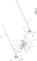
Figures 1 to 3 are perspective views of the handling system according to the invention, respectively in a locked configuration, in which the sliding of the retractable roof is prevented, in an intermediate configuration, in which rotation of the handle around a vertical axis is allowed, and in a free configuration, in which the sliding of the retractable roof is allowed; -
Figures 4 to 6 are enlarged scale views of a control assembly of the handling system, in the conditions ofFigures 1 to 3 , respectively; and -
Figures 7 and 8 are enlarged scale views of a locking member of the system, in the conditions ofFigures 1-2 and in the condition ofFigure 3 , respectively. -
Figures 1-3 show a handling system for a retractable roof, of the type that may be installed at an aperture made on a roof of a vehicle, for example a boat.Figure 1 also shows in a simplified manner a manually retractable roof, indicated by A, and the aperture intended to receive the retractable roof, indicated by B. The retractable roof A may be of any type known in the field, for example folding or sliding, flexible or rigid, and comprises a sliding end C guided alongside guides of the aperture B, not shown. In the closed position shown inFigure 1 , the end C of the retractable roof A is adjacent to a front edge D of the aperture B. The end C of the retractable roof A is able to assume a plurality of opening positions, in which such end C is distant from the front edge D of the aperture B. The sliding direction of the retractable roof A is represented by the arrow y inFigure 1 . - The retractable roof A may be locked in the closed position or in any of the open positions. For this purpose, a handling system is provided which will now be described with reference also to
Figures 4-6 . - Such handling system comprises a control assembly indicated as a whole with
reference numeral 10. Thecontrol assembly 10 includes a base orframe 11, configured to be fixed to the end C of the retractable roof A, more precisely in the center and at the lower side thereof. Thebase 11 comprises aplate 12, shown only inFigures 2 and5 , in which aguide groove 12a is formed, the function of which will be described below. Theguide groove 12a comprises arectilinear section 12a' and acircular arc section 12a" which extends from one end of therectilinear section 12a'. - The
control assembly 10 further includes ahandle support 13 mounted for rotation to thebase 11, around a first rotation axis z orthogonal to thebase 11 and therefore to the plane of the aperture B and of the retractable roof A. - The
control assembly 10 further includes a handle orgrip 14 mounted for rotation to thehandle support 13, around a second rotation axis x orthogonal to the first rotation axis z and to the sliding direction y of the retractable roof A. Thehandle 14 is also rotationally integral with thehandle support 13 relative to the first rotation axis z. - The handling system further comprises a
latching member 15 rotationally integral with thehandle support 13 and configured to couple to a respective strike member E arranged on the front edge D of the aperture B when the retractable roof A is in the closed position. - The
latching member 15 is controllable for translational motion relative to thehandle support 13 by rotating thehandle 14 around the second rotation axis x. To this end, thelatching member 15 is connected to thehandle 14 by means of a toggle mechanism (not shown). A retraction of thelatching member 15 hooked to the respective strike member E allows tensioning of the retractable roof A. - A
slider 15a is carried by thelatching member 15 and is therefore movable integrally with it. Theslider 15a engages thegroove 12a formed in thebase 11, more precisely in theplate 12. - With reference also to
Figures 7 and 8 , the handling system further comprises twolocking members 20 configured to be arranged at respective side edges of the retractable roof A. Eachlocking member 20 is supported and guided by arespective support 21, which is configured to be fixed to the retractable roof A, at a respective edge of the retractable roof A and on a lower side thereof. On thesupport 21 there is also arranged anelastic element 22, for example a spring, configured to bias therespective locking member 20 against a respective side edge of the aperture B. More precisely, atoothed belt segment 23 is arranged at each side edge of the aperture B, the toothing 23a whereof (partially shown only inFigure 1 ) faces therespective locking member 20. On its end, eachlocking member 20 has ahead 20a having a profile mating with the toothing 23a of the respectivetoothed belt segment 23. This arrangement is not essential for the purposes of the invention, since the locking between thelocking member 20 and the respective side edge of the aperture B may be obtained by other types of geometric coupling or, less preferably, by friction. - Each of the
locking members 20 may be operated away from the respective side edge of the aperture B by rotating thehandle 14 around the first rotation axis z. - To this end, the
locking members 20 are connected to thehandle support 13 byrespective traction cables 24 guided in such a way to extend in opposite radial directions with respect to the first rotation axis z. In particular, thetraction cables 24 are arranged in such a way as to extend along a line orthogonal to the sliding direction y of the retractable roof A. - The
traction cables 24 are connected to thehandle support 13 by respective connectingrods 25 hinged to thehandle support 13. In particular, the connectingrods 25 are hinged to thehandle support 13 athinge points 25a diametrically opposite with respect to the first rotation axis z. - The
handle 14 is rotatable relative to the handle support 13 between a rest position (Figures 1 and4 ) in which it lies in thehandle support 13, and a working position (Figures 2-3 and 5-6) in which it protrudes from thehandle support 13. In the working position, thehandle 14 is rotatable relative to thebase 11, along with thehandle support 13, between a first angular position (Figures 2 and5 ), in which thelatching member 15 is arranged parallel to the sliding direction y of the retractable roof A, and a second angular position (Figures 3 and6 ), in which thelatching member 15 is arranged orthogonally to the sliding direction y of the retractable roof A and thelocking members 20 are moved away from the respective edges of the aperture B. - In the second angular position, each connecting
rod 25 is arranged in such a way that therespective hinge point 25a and the respective connection point to thetraction cable 24 are in opposite positions with respect to the first rotation axis. This arrangement prevents theelastic elements 22 which act on thelatching members 21 from being able to drag therespective cables 24 on their own and therefore cause an undesired rotation of thehandle support 13 and of thehandle 14 around the first rotation axis x, bringing the latching members back 21 against thetoothed belt segment 23. - The position of the
slider 15a - integral with the latching member 15 - within thegroove 12a of thebase 11 determines in use which movements of thehandle 14 are allowed and which are instead prevented. When theslider 15a is positioned in therectilinear section 12a' of theguide groove 12a, the rotation of the handle 14 (and of the handle support 13) around the first rotation axis z is prevented and the rotation of thehandle 14 around the second rotation axis x is allowed, and when theslider 15a is positioned in thecircular arc section 12a" of theguide groove 12a, the rotation of the handle 14 (and of the handle support 13) around the first rotation axis z is allowed and the rotation of thehandle 14 around the second rotation axis x is prevented. - The operation of the handling system is now briefly described.
- In the locked position of
Figures 1 and4 , the sliding of thehandle 14 is inhibited. When thecontrol assembly 10 is approached to the front edge D of the aperture B, there is also the complete closure of the retractable roof A, and therefore with the lock position there is also the tensioning of the retractable roof A against the strike member E. It is not possible to rotate thehandle 14 around the first rotation axis z because theslider 15a, integral with thelatching member 15, is engaged in therectilinear section 12a' of theguide groove 12a. - By rotating the
handle 14 around the second horizontal axis x (Figures 2 and5 ), by means of the toggle mechanism not shown, thelatching member 15 is pushed forward, releasing the retractable roof A and moving theslider 15a in thecircular section 12a" of thegroove 12a. It is then possible to rotate thehandle 14. - By rotating the
handle 14 along the first vertical axis z (Figures 3 and6 ), by means of the connectingrods 25 and thetraction cables 24, thelocking members 20 are actuated which then move away from the respectivetoothed belt segments 23. It is then possible to slide the end C of the roof A crosswise along the respective guides and open the roof. - Once a desired opening position has been reached, it is possible to lock the roof A in this position by rotating the
handle 14 around the first axis z in the opposite direction with respect to what has been described above. This movement, in fact, loads thelocking members 20 allowing the relativeelastic elements 22 to bring them back to engagement with the respectivetoothed belt segments 23. Thebelt segments 23 are present for the entire length of the stroke of the roof A and therefore allow locking in any position, except in the section immediately adjacent to the closure of the retractable roof to allow the roof to be tensioned. - It is understood that the invention is not limited to the embodiments described and illustrated herein, but is instead susceptible of modifications relating to the shape and arrangement of parts, constructional and operating details, according to the numerous possible variants which will appear suitable to the man skilled in the art and which are to be understood as included in the scope of the invention, as defined by the following claims.
Claims (6)
- A handling system for a manually retractable roof (A), said retractable roof having an end (C) slidable between a closure position, in which said end is adjacent to a front edge (D) of an aperture (B) of the retractable roof, and a plurality of opening positions, the system comprising
a control assembly (10) that includes a base (11) configured to be fixed to said end of the retractable roof, a handle support (13) mounted for rotation to the base (11), around a first rotation axis (z) orthogonal to the base (11), and a handle (14) mounted for rotation to the handle support (13), around a second rotation axis (x) orthogonal to the first rotation axis (z), said handle being further rotationally integral with the handle support (13) with respect to the first rotation axis (z),
a latching member (15) rotationally integral with the handle support (13) and configured to couple to a respective strike member (E) arranged on said front edge of the aperture of the retractable roof when the retractable roof (A) is in the closure position, said latching member being controllable for translational motion relative to the handle support (13) by rotation of the handle (14) around the second rotation axis (x), wherein a retraction of the latching member (15) coupled to the respective strike member (E) allows for tensioning of the retractable roof (A), and
two locking members (20) configured to be arranged at respective side edges of the retractable roof (A), each of said locking members being elastically biased against a respective side edge (23) of the aperture (B) of the retractable roof, and being controllable for moving away from the respective side edge (23) of the aperture (B) of the retractable roof by rotation of the handle (14) around the first rotation axis (z). - A system according to claim 1, wherein the handle (14) is rotatable relative to the handle support (13) between a rest position in which the handle lies in the handle support (13), and a working position in which the handle protrudes from the handle support (13), and wherein in the working position the handle (14) is rotatable relative to the base (11), along with the handle support (13), between a first angular position, in which the latching member (15) is arranged parallel to a sliding direction (y) of the retractable roof (A), and a second angular position, in which the latching member (15) is arranged orthogonal to the sliding direction (y) of the retractable roof (A).
- A system according to claim 2, wherein in the base (11) of the control assembly (10) there is formed a guide groove (12a) engaged by a slider (15a) carried by the latching member (15), said groove comprising a rectilinear section (12a') and a circular arc section (12a") extending from an end of the rectilinear section (12a'), wherein when said slider is positioned in the rectilinear section (12a') of the guide groove (12a) rotation of the handle (14) around the first rotation axis (z) is prevented and rotation of the handle (14) around the second rotation axis (x) is allowed, and when said slider is positioned in the circular arc section (12a") of the guide groove (12a) rotation of the handle (14) around the first rotation axis (z) is allowed and rotation of the handle (14) around the second rotation axis (x) is prevented.
- A system according to any of the preceding claims, wherein the locking members (20) are connected to the handle support (13) by respective traction cables (24) guided in such a way to extend in opposite radial directions with respect to the first rotation axis (z).
- A system according to claim 4, wherein the traction cables (24) are connected to the handle support (13) by respective connecting rods (25) hinged to the handle support (13).
- A system according to claims 2 and 5, wherein said connecting rods are hinged to the handle support (13) at hinge points (25a) diametrically opposite with respect to the first rotation axis (z), and wherein in the second angular position each connecting rod (25) is arranged in such a way that the respective hinge point (25a) and the respective point of connection with the traction cable (24) are on opposite positions with respect to the first rotation axis (z).
Applications Claiming Priority (1)
| Application Number | Priority Date | Filing Date | Title |
|---|---|---|---|
| IT102019000021402A IT201900021402A1 (en) | 2019-11-18 | 2019-11-18 | Maneuvering system for a manual retractable roof |
Publications (2)
| Publication Number | Publication Date |
|---|---|
| EP3822104A1 true EP3822104A1 (en) | 2021-05-19 |
| EP3822104B1 EP3822104B1 (en) | 2022-10-12 |
Family
ID=69903934
Family Applications (1)
| Application Number | Title | Priority Date | Filing Date |
|---|---|---|---|
| EP20208064.4A Active EP3822104B1 (en) | 2019-11-18 | 2020-11-17 | Handling system for a manual retractable roof |
Country Status (2)
| Country | Link |
|---|---|
| EP (1) | EP3822104B1 (en) |
| IT (1) | IT201900021402A1 (en) |
Citations (9)
| Publication number | Priority date | Publication date | Assignee | Title |
|---|---|---|---|---|
| DE3206292A1 (en) * | 1981-03-17 | 1982-12-23 | Aisin Seiki K.K., Kariya, Aichi | LOCKING DEVICE FOR A REMOVABLE SUN PROTECTION FOR A VEHICLE |
| DE29717325U1 (en) * | 1997-09-27 | 1998-07-16 | Wilhelm Karmann GmbH, 49084 Osnabrück | Cabriolet vehicle |
| EP1110784A2 (en) * | 1999-12-22 | 2001-06-27 | Edscha Cabrio-Verdecksysteme GmbH | Locking device for a foldable vehicle cover |
| DE202004005257U1 (en) * | 2004-04-02 | 2004-05-27 | Wilhelm Karmann Gmbh | Locking device for a convertible top of a convertible motor vehicle |
| EP1798085A1 (en) * | 2005-12-16 | 2007-06-20 | Wilhelm Karmann GmbH | Vehicle roof system for a cabriolet |
| DE102007027259A1 (en) * | 2007-06-13 | 2008-12-18 | Wilhelm Karmann Gmbh | Closing device for a hood of a convertible motor vehicle |
| DE102013102441A1 (en) * | 2013-03-12 | 2014-10-02 | Webasto-Edscha Cabrio GmbH | Locking device for an adjustable roof part of a vehicle roof |
| DE102015107725A1 (en) * | 2014-05-20 | 2015-11-26 | Asmo Co., Ltd. | Clutch motor and device for opening and closing an openable body |
| US20180015813A1 (en) * | 2016-07-14 | 2018-01-18 | Webasto SE | Locking Device Having a Locking Hook and a Detection Device for a Locking-Hook Position |
-
2019
- 2019-11-18 IT IT102019000021402A patent/IT201900021402A1/en unknown
-
2020
- 2020-11-17 EP EP20208064.4A patent/EP3822104B1/en active Active
Patent Citations (9)
| Publication number | Priority date | Publication date | Assignee | Title |
|---|---|---|---|---|
| DE3206292A1 (en) * | 1981-03-17 | 1982-12-23 | Aisin Seiki K.K., Kariya, Aichi | LOCKING DEVICE FOR A REMOVABLE SUN PROTECTION FOR A VEHICLE |
| DE29717325U1 (en) * | 1997-09-27 | 1998-07-16 | Wilhelm Karmann GmbH, 49084 Osnabrück | Cabriolet vehicle |
| EP1110784A2 (en) * | 1999-12-22 | 2001-06-27 | Edscha Cabrio-Verdecksysteme GmbH | Locking device for a foldable vehicle cover |
| DE202004005257U1 (en) * | 2004-04-02 | 2004-05-27 | Wilhelm Karmann Gmbh | Locking device for a convertible top of a convertible motor vehicle |
| EP1798085A1 (en) * | 2005-12-16 | 2007-06-20 | Wilhelm Karmann GmbH | Vehicle roof system for a cabriolet |
| DE102007027259A1 (en) * | 2007-06-13 | 2008-12-18 | Wilhelm Karmann Gmbh | Closing device for a hood of a convertible motor vehicle |
| DE102013102441A1 (en) * | 2013-03-12 | 2014-10-02 | Webasto-Edscha Cabrio GmbH | Locking device for an adjustable roof part of a vehicle roof |
| DE102015107725A1 (en) * | 2014-05-20 | 2015-11-26 | Asmo Co., Ltd. | Clutch motor and device for opening and closing an openable body |
| US20180015813A1 (en) * | 2016-07-14 | 2018-01-18 | Webasto SE | Locking Device Having a Locking Hook and a Detection Device for a Locking-Hook Position |
Also Published As
| Publication number | Publication date |
|---|---|
| IT201900021402A1 (en) | 2021-05-18 |
| EP3822104B1 (en) | 2022-10-12 |
Similar Documents
| Publication | Publication Date | Title |
|---|---|---|
| US9315123B2 (en) | Child safety seat assemblies having anchor systems | |
| US11565612B2 (en) | Child restraint spin lock and a safety seat having the same | |
| AU754311B2 (en) | Crash-helmet with device for locking and releasing movable parts | |
| US9096981B2 (en) | Snowblower adjustable deflector control devices, systems, and methods | |
| US20040200150A1 (en) | Tilt latch mechanism for hung windows | |
| ES2897412T3 (en) | Drive trolley for one door as well as door drive | |
| US8876201B2 (en) | Vehicle sun roof apparatus | |
| US20130019536A1 (en) | Separating element for a platform cabin comprising a push rod mechanism for moving a leaf | |
| EP3774211B1 (en) | A hair cutting device | |
| EP3822104A1 (en) | Handling system for a manual retractable roof | |
| US4491344A (en) | Safety belt system for motor vehicles | |
| EP4465282A1 (en) | Edge locking apparatus of led display screen and led display screen | |
| EP2674312B1 (en) | Openable roof system for a vehicle | |
| CN107567276A (en) | Manually operated cutting device | |
| JP2008024300A (en) | Shielding device for automobile having locking means and corresponding automobile | |
| KR102595745B1 (en) | Assembly and method for moving the cover | |
| US20070241651A1 (en) | Drawer slide with releasable latch | |
| EP3517702A1 (en) | Locking system for a pergola-type canopy | |
| US20170158037A1 (en) | Glazed roof with a mobile panel controlled by shuttles | |
| EP2772403B1 (en) | Cable transportation system switch | |
| EP2944491A1 (en) | Open roof system for a vehicle | |
| JPH10148241A (en) | Lock device for mesh mechanism | |
| EP3927569B1 (en) | Roof assembly for a work vehicle | |
| CN114497986B (en) | Stop structure and antenna downward inclination angle adjusting device | |
| KR20200066722A (en) | Self-locking lock with multi-point locking drive |
Legal Events
| Date | Code | Title | Description |
|---|---|---|---|
| PUAI | Public reference made under article 153(3) epc to a published international application that has entered the european phase |
Free format text: ORIGINAL CODE: 0009012 |
|
| STAA | Information on the status of an ep patent application or granted ep patent |
Free format text: STATUS: THE APPLICATION HAS BEEN PUBLISHED |
|
| AK | Designated contracting states |
Kind code of ref document: A1 Designated state(s): AL AT BE BG CH CY CZ DE DK EE ES FI FR GB GR HR HU IE IS IT LI LT LU LV MC MK MT NL NO PL PT RO RS SE SI SK SM TR |
|
| STAA | Information on the status of an ep patent application or granted ep patent |
Free format text: STATUS: REQUEST FOR EXAMINATION WAS MADE |
|
| 17P | Request for examination filed |
Effective date: 20211109 |
|
| RBV | Designated contracting states (corrected) |
Designated state(s): AL AT BE BG CH CY CZ DE DK EE ES FI FR GB GR HR HU IE IS IT LI LT LU LV MC MK MT NL NO PL PT RO RS SE SI SK SM TR |
|
| GRAP | Despatch of communication of intention to grant a patent |
Free format text: ORIGINAL CODE: EPIDOSNIGR1 |
|
| STAA | Information on the status of an ep patent application or granted ep patent |
Free format text: STATUS: GRANT OF PATENT IS INTENDED |
|
| INTG | Intention to grant announced |
Effective date: 20220504 |
|
| GRAS | Grant fee paid |
Free format text: ORIGINAL CODE: EPIDOSNIGR3 |
|
| GRAA | (expected) grant |
Free format text: ORIGINAL CODE: 0009210 |
|
| STAA | Information on the status of an ep patent application or granted ep patent |
Free format text: STATUS: THE PATENT HAS BEEN GRANTED |
|
| AK | Designated contracting states |
Kind code of ref document: B1 Designated state(s): AL AT BE BG CH CY CZ DE DK EE ES FI FR GB GR HR HU IE IS IT LI LT LU LV MC MK MT NL NO PL PT RO RS SE SI SK SM TR |
|
| REG | Reference to a national code |
Ref country code: GB Ref legal event code: FG4D |
|
| REG | Reference to a national code |
Ref country code: CH Ref legal event code: EP |
|
| REG | Reference to a national code |
Ref country code: DE Ref legal event code: R096 Ref document number: 602020005583 Country of ref document: DE |
|
| REG | Reference to a national code |
Ref country code: IE Ref legal event code: FG4D |
|
| REG | Reference to a national code |
Ref country code: AT Ref legal event code: REF Ref document number: 1523952 Country of ref document: AT Kind code of ref document: T Effective date: 20221115 |
|
| REG | Reference to a national code |
Ref country code: LT Ref legal event code: MG9D |
|
| REG | Reference to a national code |
Ref country code: NL Ref legal event code: MP Effective date: 20221012 |
|
| REG | Reference to a national code |
Ref country code: AT Ref legal event code: MK05 Ref document number: 1523952 Country of ref document: AT Kind code of ref document: T Effective date: 20221012 |
|
| PG25 | Lapsed in a contracting state [announced via postgrant information from national office to epo] |
Ref country code: NL Free format text: LAPSE BECAUSE OF FAILURE TO SUBMIT A TRANSLATION OF THE DESCRIPTION OR TO PAY THE FEE WITHIN THE PRESCRIBED TIME-LIMIT Effective date: 20221012 |
|
| PG25 | Lapsed in a contracting state [announced via postgrant information from national office to epo] |
Ref country code: SE Free format text: LAPSE BECAUSE OF FAILURE TO SUBMIT A TRANSLATION OF THE DESCRIPTION OR TO PAY THE FEE WITHIN THE PRESCRIBED TIME-LIMIT Effective date: 20221012 Ref country code: PT Free format text: LAPSE BECAUSE OF FAILURE TO SUBMIT A TRANSLATION OF THE DESCRIPTION OR TO PAY THE FEE WITHIN THE PRESCRIBED TIME-LIMIT Effective date: 20230213 Ref country code: NO Free format text: LAPSE BECAUSE OF FAILURE TO SUBMIT A TRANSLATION OF THE DESCRIPTION OR TO PAY THE FEE WITHIN THE PRESCRIBED TIME-LIMIT Effective date: 20230112 Ref country code: LT Free format text: LAPSE BECAUSE OF FAILURE TO SUBMIT A TRANSLATION OF THE DESCRIPTION OR TO PAY THE FEE WITHIN THE PRESCRIBED TIME-LIMIT Effective date: 20221012 Ref country code: FI Free format text: LAPSE BECAUSE OF FAILURE TO SUBMIT A TRANSLATION OF THE DESCRIPTION OR TO PAY THE FEE WITHIN THE PRESCRIBED TIME-LIMIT Effective date: 20221012 Ref country code: ES Free format text: LAPSE BECAUSE OF FAILURE TO SUBMIT A TRANSLATION OF THE DESCRIPTION OR TO PAY THE FEE WITHIN THE PRESCRIBED TIME-LIMIT Effective date: 20221012 Ref country code: AT Free format text: LAPSE BECAUSE OF FAILURE TO SUBMIT A TRANSLATION OF THE DESCRIPTION OR TO PAY THE FEE WITHIN THE PRESCRIBED TIME-LIMIT Effective date: 20221012 |
|
| PG25 | Lapsed in a contracting state [announced via postgrant information from national office to epo] |
Ref country code: RS Free format text: LAPSE BECAUSE OF FAILURE TO SUBMIT A TRANSLATION OF THE DESCRIPTION OR TO PAY THE FEE WITHIN THE PRESCRIBED TIME-LIMIT Effective date: 20221012 Ref country code: PL Free format text: LAPSE BECAUSE OF FAILURE TO SUBMIT A TRANSLATION OF THE DESCRIPTION OR TO PAY THE FEE WITHIN THE PRESCRIBED TIME-LIMIT Effective date: 20221012 Ref country code: LV Free format text: LAPSE BECAUSE OF FAILURE TO SUBMIT A TRANSLATION OF THE DESCRIPTION OR TO PAY THE FEE WITHIN THE PRESCRIBED TIME-LIMIT Effective date: 20221012 Ref country code: IS Free format text: LAPSE BECAUSE OF FAILURE TO SUBMIT A TRANSLATION OF THE DESCRIPTION OR TO PAY THE FEE WITHIN THE PRESCRIBED TIME-LIMIT Effective date: 20230212 Ref country code: HR Free format text: LAPSE BECAUSE OF FAILURE TO SUBMIT A TRANSLATION OF THE DESCRIPTION OR TO PAY THE FEE WITHIN THE PRESCRIBED TIME-LIMIT Effective date: 20221012 Ref country code: GR Free format text: LAPSE BECAUSE OF FAILURE TO SUBMIT A TRANSLATION OF THE DESCRIPTION OR TO PAY THE FEE WITHIN THE PRESCRIBED TIME-LIMIT Effective date: 20230113 |
|
| REG | Reference to a national code |
Ref country code: DE Ref legal event code: R119 Ref document number: 602020005583 Country of ref document: DE |
|
| REG | Reference to a national code |
Ref country code: BE Ref legal event code: MM Effective date: 20221130 |
|
| PG25 | Lapsed in a contracting state [announced via postgrant information from national office to epo] |
Ref country code: SM Free format text: LAPSE BECAUSE OF FAILURE TO SUBMIT A TRANSLATION OF THE DESCRIPTION OR TO PAY THE FEE WITHIN THE PRESCRIBED TIME-LIMIT Effective date: 20221012 Ref country code: RO Free format text: LAPSE BECAUSE OF FAILURE TO SUBMIT A TRANSLATION OF THE DESCRIPTION OR TO PAY THE FEE WITHIN THE PRESCRIBED TIME-LIMIT Effective date: 20221012 Ref country code: MC Free format text: LAPSE BECAUSE OF FAILURE TO SUBMIT A TRANSLATION OF THE DESCRIPTION OR TO PAY THE FEE WITHIN THE PRESCRIBED TIME-LIMIT Effective date: 20221012 Ref country code: EE Free format text: LAPSE BECAUSE OF FAILURE TO SUBMIT A TRANSLATION OF THE DESCRIPTION OR TO PAY THE FEE WITHIN THE PRESCRIBED TIME-LIMIT Effective date: 20221012 Ref country code: DK Free format text: LAPSE BECAUSE OF FAILURE TO SUBMIT A TRANSLATION OF THE DESCRIPTION OR TO PAY THE FEE WITHIN THE PRESCRIBED TIME-LIMIT Effective date: 20221012 Ref country code: CZ Free format text: LAPSE BECAUSE OF FAILURE TO SUBMIT A TRANSLATION OF THE DESCRIPTION OR TO PAY THE FEE WITHIN THE PRESCRIBED TIME-LIMIT Effective date: 20221012 |
|
| PLBE | No opposition filed within time limit |
Free format text: ORIGINAL CODE: 0009261 |
|
| STAA | Information on the status of an ep patent application or granted ep patent |
Free format text: STATUS: NO OPPOSITION FILED WITHIN TIME LIMIT |
|
| PG25 | Lapsed in a contracting state [announced via postgrant information from national office to epo] |
Ref country code: SK Free format text: LAPSE BECAUSE OF FAILURE TO SUBMIT A TRANSLATION OF THE DESCRIPTION OR TO PAY THE FEE WITHIN THE PRESCRIBED TIME-LIMIT Effective date: 20221012 Ref country code: LU Free format text: LAPSE BECAUSE OF NON-PAYMENT OF DUE FEES Effective date: 20221117 Ref country code: AL Free format text: LAPSE BECAUSE OF FAILURE TO SUBMIT A TRANSLATION OF THE DESCRIPTION OR TO PAY THE FEE WITHIN THE PRESCRIBED TIME-LIMIT Effective date: 20221012 |
|
| 26N | No opposition filed |
Effective date: 20230713 |
|
| PG25 | Lapsed in a contracting state [announced via postgrant information from national office to epo] |
Ref country code: IE Free format text: LAPSE BECAUSE OF NON-PAYMENT OF DUE FEES Effective date: 20221117 Ref country code: DE Free format text: LAPSE BECAUSE OF NON-PAYMENT OF DUE FEES Effective date: 20230601 |
|
| PG25 | Lapsed in a contracting state [announced via postgrant information from national office to epo] |
Ref country code: SI Free format text: LAPSE BECAUSE OF FAILURE TO SUBMIT A TRANSLATION OF THE DESCRIPTION OR TO PAY THE FEE WITHIN THE PRESCRIBED TIME-LIMIT Effective date: 20221012 Ref country code: BE Free format text: LAPSE BECAUSE OF NON-PAYMENT OF DUE FEES Effective date: 20221130 |
|
| PG25 | Lapsed in a contracting state [announced via postgrant information from national office to epo] |
Ref country code: CY Free format text: LAPSE BECAUSE OF FAILURE TO SUBMIT A TRANSLATION OF THE DESCRIPTION OR TO PAY THE FEE WITHIN THE PRESCRIBED TIME-LIMIT Effective date: 20221012 |
|
| PG25 | Lapsed in a contracting state [announced via postgrant information from national office to epo] |
Ref country code: MK Free format text: LAPSE BECAUSE OF FAILURE TO SUBMIT A TRANSLATION OF THE DESCRIPTION OR TO PAY THE FEE WITHIN THE PRESCRIBED TIME-LIMIT Effective date: 20221012 Ref country code: IT Free format text: LAPSE BECAUSE OF FAILURE TO SUBMIT A TRANSLATION OF THE DESCRIPTION OR TO PAY THE FEE WITHIN THE PRESCRIBED TIME-LIMIT Effective date: 20221012 |
|
| PGFP | Annual fee paid to national office [announced via postgrant information from national office to epo] |
Ref country code: FR Payment date: 20240329 Year of fee payment: 4 |
|
| REG | Reference to a national code |
Ref country code: CH Ref legal event code: PL |
|
| PG25 | Lapsed in a contracting state [announced via postgrant information from national office to epo] |
Ref country code: CH Free format text: LAPSE BECAUSE OF NON-PAYMENT OF DUE FEES Effective date: 20231130 |
|
| PG25 | Lapsed in a contracting state [announced via postgrant information from national office to epo] |
Ref country code: HU Free format text: LAPSE BECAUSE OF FAILURE TO SUBMIT A TRANSLATION OF THE DESCRIPTION OR TO PAY THE FEE WITHIN THE PRESCRIBED TIME-LIMIT; INVALID AB INITIO Effective date: 20201117 Ref country code: CH Free format text: LAPSE BECAUSE OF NON-PAYMENT OF DUE FEES Effective date: 20231130 Ref country code: BG Free format text: LAPSE BECAUSE OF FAILURE TO SUBMIT A TRANSLATION OF THE DESCRIPTION OR TO PAY THE FEE WITHIN THE PRESCRIBED TIME-LIMIT Effective date: 20221012 |
|
| PG25 | Lapsed in a contracting state [announced via postgrant information from national office to epo] |
Ref country code: MT Free format text: LAPSE BECAUSE OF FAILURE TO SUBMIT A TRANSLATION OF THE DESCRIPTION OR TO PAY THE FEE WITHIN THE PRESCRIBED TIME-LIMIT Effective date: 20221012 |
|
| GBPC | Gb: european patent ceased through non-payment of renewal fee |
Effective date: 20241117 |
|
| PG25 | Lapsed in a contracting state [announced via postgrant information from national office to epo] |
Ref country code: GB Free format text: LAPSE BECAUSE OF NON-PAYMENT OF DUE FEES Effective date: 20241117 |
|
| PG25 | Lapsed in a contracting state [announced via postgrant information from national office to epo] |
Ref country code: FR Free format text: LAPSE BECAUSE OF NON-PAYMENT OF DUE FEES Effective date: 20241130 |
|
| PG25 | Lapsed in a contracting state [announced via postgrant information from national office to epo] |
Ref country code: TR Free format text: LAPSE BECAUSE OF FAILURE TO SUBMIT A TRANSLATION OF THE DESCRIPTION OR TO PAY THE FEE WITHIN THE PRESCRIBED TIME-LIMIT Effective date: 20221012 |