EP3822079A1 - Self-supporting additively-manufactured heat exchanger header - Google Patents
Self-supporting additively-manufactured heat exchanger header Download PDFInfo
- Publication number
- EP3822079A1 EP3822079A1 EP20207805.1A EP20207805A EP3822079A1 EP 3822079 A1 EP3822079 A1 EP 3822079A1 EP 20207805 A EP20207805 A EP 20207805A EP 3822079 A1 EP3822079 A1 EP 3822079A1
- Authority
- EP
- European Patent Office
- Prior art keywords
- heat exchanger
- header
- additively
- defines
- fluid
- Prior art date
- Legal status (The legal status is an assumption and is not a legal conclusion. Google has not performed a legal analysis and makes no representation as to the accuracy of the status listed.)
- Granted
Links
Images

Classifications
-
- F—MECHANICAL ENGINEERING; LIGHTING; HEATING; WEAPONS; BLASTING
- F28—HEAT EXCHANGE IN GENERAL
- F28F—DETAILS OF HEAT-EXCHANGE AND HEAT-TRANSFER APPARATUS, OF GENERAL APPLICATION
- F28F9/00—Casings; Header boxes; Auxiliary supports for elements; Auxiliary members within casings
- F28F9/02—Header boxes; End plates
- F28F9/026—Header boxes; End plates with static flow control means, e.g. with means for uniformly distributing heat exchange media into conduits
- F28F9/0263—Header boxes; End plates with static flow control means, e.g. with means for uniformly distributing heat exchange media into conduits by varying the geometry or cross-section of header box
-
- B—PERFORMING OPERATIONS; TRANSPORTING
- B22—CASTING; POWDER METALLURGY
- B22F—WORKING METALLIC POWDER; MANUFACTURE OF ARTICLES FROM METALLIC POWDER; MAKING METALLIC POWDER; APPARATUS OR DEVICES SPECIALLY ADAPTED FOR METALLIC POWDER
- B22F10/00—Additive manufacturing of workpieces or articles from metallic powder
-
- B—PERFORMING OPERATIONS; TRANSPORTING
- B22—CASTING; POWDER METALLURGY
- B22F—WORKING METALLIC POWDER; MANUFACTURE OF ARTICLES FROM METALLIC POWDER; MAKING METALLIC POWDER; APPARATUS OR DEVICES SPECIALLY ADAPTED FOR METALLIC POWDER
- B22F10/00—Additive manufacturing of workpieces or articles from metallic powder
- B22F10/20—Direct sintering or melting
- B22F10/28—Powder bed fusion, e.g. selective laser melting [SLM] or electron beam melting [EBM]
-
- B—PERFORMING OPERATIONS; TRANSPORTING
- B22—CASTING; POWDER METALLURGY
- B22F—WORKING METALLIC POWDER; MANUFACTURE OF ARTICLES FROM METALLIC POWDER; MAKING METALLIC POWDER; APPARATUS OR DEVICES SPECIALLY ADAPTED FOR METALLIC POWDER
- B22F10/00—Additive manufacturing of workpieces or articles from metallic powder
- B22F10/40—Structures for supporting workpieces or articles during manufacture and removed afterwards
- B22F10/47—Structures for supporting workpieces or articles during manufacture and removed afterwards characterised by structural features
-
- B—PERFORMING OPERATIONS; TRANSPORTING
- B22—CASTING; POWDER METALLURGY
- B22F—WORKING METALLIC POWDER; MANUFACTURE OF ARTICLES FROM METALLIC POWDER; MAKING METALLIC POWDER; APPARATUS OR DEVICES SPECIALLY ADAPTED FOR METALLIC POWDER
- B22F5/00—Manufacture of workpieces or articles from metallic powder characterised by the special shape of the product
- B22F5/10—Manufacture of workpieces or articles from metallic powder characterised by the special shape of the product of articles with cavities or holes, not otherwise provided for in the preceding subgroups
-
- B—PERFORMING OPERATIONS; TRANSPORTING
- B33—ADDITIVE MANUFACTURING TECHNOLOGY
- B33Y—ADDITIVE MANUFACTURING, i.e. MANUFACTURING OF THREE-DIMENSIONAL [3D] OBJECTS BY ADDITIVE DEPOSITION, ADDITIVE AGGLOMERATION OR ADDITIVE LAYERING, e.g. BY 3D PRINTING, STEREOLITHOGRAPHY OR SELECTIVE LASER SINTERING
- B33Y10/00—Processes of additive manufacturing
-
- B—PERFORMING OPERATIONS; TRANSPORTING
- B33—ADDITIVE MANUFACTURING TECHNOLOGY
- B33Y—ADDITIVE MANUFACTURING, i.e. MANUFACTURING OF THREE-DIMENSIONAL [3D] OBJECTS BY ADDITIVE DEPOSITION, ADDITIVE AGGLOMERATION OR ADDITIVE LAYERING, e.g. BY 3D PRINTING, STEREOLITHOGRAPHY OR SELECTIVE LASER SINTERING
- B33Y70/00—Materials specially adapted for additive manufacturing
-
- B—PERFORMING OPERATIONS; TRANSPORTING
- B33—ADDITIVE MANUFACTURING TECHNOLOGY
- B33Y—ADDITIVE MANUFACTURING, i.e. MANUFACTURING OF THREE-DIMENSIONAL [3D] OBJECTS BY ADDITIVE DEPOSITION, ADDITIVE AGGLOMERATION OR ADDITIVE LAYERING, e.g. BY 3D PRINTING, STEREOLITHOGRAPHY OR SELECTIVE LASER SINTERING
- B33Y80/00—Products made by additive manufacturing
-
- F—MECHANICAL ENGINEERING; LIGHTING; HEATING; WEAPONS; BLASTING
- F28—HEAT EXCHANGE IN GENERAL
- F28F—DETAILS OF HEAT-EXCHANGE AND HEAT-TRANSFER APPARATUS, OF GENERAL APPLICATION
- F28F9/00—Casings; Header boxes; Auxiliary supports for elements; Auxiliary members within casings
- F28F9/02—Header boxes; End plates
-
- B—PERFORMING OPERATIONS; TRANSPORTING
- B22—CASTING; POWDER METALLURGY
- B22F—WORKING METALLIC POWDER; MANUFACTURE OF ARTICLES FROM METALLIC POWDER; MAKING METALLIC POWDER; APPARATUS OR DEVICES SPECIALLY ADAPTED FOR METALLIC POWDER
- B22F2999/00—Aspects linked to processes or compositions used in powder metallurgy
-
- F—MECHANICAL ENGINEERING; LIGHTING; HEATING; WEAPONS; BLASTING
- F28—HEAT EXCHANGE IN GENERAL
- F28F—DETAILS OF HEAT-EXCHANGE AND HEAT-TRANSFER APPARATUS, OF GENERAL APPLICATION
- F28F9/00—Casings; Header boxes; Auxiliary supports for elements; Auxiliary members within casings
- F28F9/02—Header boxes; End plates
- F28F2009/0285—Other particular headers or end plates
- F28F2009/0292—Other particular headers or end plates with fins
-
- F—MECHANICAL ENGINEERING; LIGHTING; HEATING; WEAPONS; BLASTING
- F28—HEAT EXCHANGE IN GENERAL
- F28F—DETAILS OF HEAT-EXCHANGE AND HEAT-TRANSFER APPARATUS, OF GENERAL APPLICATION
- F28F9/00—Casings; Header boxes; Auxiliary supports for elements; Auxiliary members within casings
- F28F9/02—Header boxes; End plates
- F28F2009/0285—Other particular headers or end plates
- F28F2009/0297—Side headers, e.g. for radiators having conduits laterally connected to common header
-
- F—MECHANICAL ENGINEERING; LIGHTING; HEATING; WEAPONS; BLASTING
- F28—HEAT EXCHANGE IN GENERAL
- F28F—DETAILS OF HEAT-EXCHANGE AND HEAT-TRANSFER APPARATUS, OF GENERAL APPLICATION
- F28F2225/00—Reinforcing means
- F28F2225/08—Reinforcing means for header boxes
-
- F—MECHANICAL ENGINEERING; LIGHTING; HEATING; WEAPONS; BLASTING
- F28—HEAT EXCHANGE IN GENERAL
- F28F—DETAILS OF HEAT-EXCHANGE AND HEAT-TRANSFER APPARATUS, OF GENERAL APPLICATION
- F28F9/00—Casings; Header boxes; Auxiliary supports for elements; Auxiliary members within casings
- F28F9/02—Header boxes; End plates
- F28F9/0219—Arrangements for sealing end plates into casing or header box; Header box sub-elements
- F28F9/0224—Header boxes formed by sealing end plates into covers
-
- Y—GENERAL TAGGING OF NEW TECHNOLOGICAL DEVELOPMENTS; GENERAL TAGGING OF CROSS-SECTIONAL TECHNOLOGIES SPANNING OVER SEVERAL SECTIONS OF THE IPC; TECHNICAL SUBJECTS COVERED BY FORMER USPC CROSS-REFERENCE ART COLLECTIONS [XRACs] AND DIGESTS
- Y02—TECHNOLOGIES OR APPLICATIONS FOR MITIGATION OR ADAPTATION AGAINST CLIMATE CHANGE
- Y02P—CLIMATE CHANGE MITIGATION TECHNOLOGIES IN THE PRODUCTION OR PROCESSING OF GOODS
- Y02P10/00—Technologies related to metal processing
- Y02P10/25—Process efficiency
Definitions
- the present disclosure relates to heat exchangers, and more particularly, to a self-supporting additively-manufactured heat exchanger header that improves the manufacturability and performance of the heat exchanger.
- Heat exchangers are well known in the aviation arts and in other industries for providing a compact, low-weight, and highly-effective means of exchanging heat from a hot fluid to a cold fluid. Heat exchangers that operate at elevated temperatures often have short service lives and/or require increased maintenance as a result of high cyclic thermal stress. The stress is caused by multiple system and component factors including rapid flow and/or temperature transients, geometric discontinuities, stiffness discontinuities, mass discontinuities, and materials of construction.
- inlet and outlet headers are typically pressure vessels that are welded or bolted to a heat exchanger core or matrix. Pressure requirements dictate the thickness of these manifolds, sometimes resulting in a relatively thick header attached to a thinner core matrix. This mismatch in thickness and mass, while acceptable for pressure loads, conflicts with the goal of avoiding discontinuities to limit thermal stress.
- Additive manufacturing can be used to build a heat exchanger core and headers as an integral unit, thereby overcoming some of aforementioned disadvantages. Moreover, the need to metallurgically attach headers to a heat exchanger core is avoided, thereby avoiding several possible disadvantages that can be associated with welding or brazing processes.
- an integral heat exchanger core and header can be built up layer-by-layer against the direction of gravity. While many areas of a heat exchanger and header can be readily fabricated using additive manufacturing techniques, difficulty can occur in building the upper region of the headers, where an overhang must be fashioned.
- Massive internal support structures can be provided for additively-manufacturing the overhang, resulting in fluid flow restrictions, increased mass and the associated mass discontinuities, geometric discontinuities, and stiffness discontinuities. Accordingly, there is a need for a self-supporting additively-manufactured heat exchanger header that overcomes these disadvantages.
- An additively-manufactured heat exchanger header defines a build plane and a vertical axis defining a build direction that is orthogonal to the build plane.
- the additively-manufactured heat exchanger header includes a header body configured to at least partially contain a working fluid and an upper support structure on the header body.
- the upper support structure defines an interior edge and includes a branchwork of gussets rising upward and outward from a root point located in the middle region on the header body.
- the header body defines a middle region, an upper region, and a top extension.
- the branchwork of gussets forms a number of top vanes, each supporting the top extension.
- the upper region is oriented over the middle region relative to the vertical axis, and the top extension partially defines the fluid boundary and is oriented over the upper region.
- the method includes building a header body configured to at least partially contain a working fluid, the header body defining a middle region, an upper region oriented over the middle region relative to the vertical axis, and a top extension that partially defines the fluid boundary and is oriented over the upper region, and building an upper support structure on the header body.
- the upper support structure includes a branchwork of gussets rising upward and outward from a root point located in the middle region on the header body, the branchwork of gussets forming a number of top vanes, each supporting the top extension.
- the header body and the upper support structure are built concurrently in the build direction.
- the present disclosure is directed to an additively-manufactured heat exchanger header having a self-supporting design.
- a self-supporting header is shown in an exemplary embodiment on a hot circuit of a heat exchanger core. Accordingly, the hot circuit of a heat exchanger is disclosed.
- a heat exchanger utilizing the self-supporting header of the present embodiment also includes a cold circuit.
- the cold circuit can also include inlet and outlet headers that can be similar to the self-supporting header of the present disclosure.
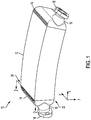
- FIG. 1 is a perspective view of an additively-manufactured heat exchanger. Shown in FIG. 1 are heat exchanger 10, core 12, headers 14, nozzles 16, and flanges 18. The x-y-z coordinate axes are also labeled in FIG. 1 , with the x-y axes defining the additive-manufacturing (AM) build plane, and the z axis defining the additive-manufacturing build direction. During an additive-manufacturing process the build direction is upward, against gravity. Therefore, heat exchanger 10 depicted in FIG. 1 has been rotated 90 degrees following its manufacture (i.e., the z axis, in reference to heat exchanger 10, is oriented approximately in the horizontal direction as shown in FIG. 1 ).
- AM additive-manufacturing
- Heat exchanger 10 includes core 12 which transfers heat from one fluid to another while maintaining a fluid separation between the two fluid circuits. Heat will generally flow from the hot fluid to the cold fluid across the various components within core 12. Therefore, as used in this disclosure, “hot” will be used to describe the first fluid circuit and “cold” will be used to describe the second fluid circuit. The terms “hot” and “cold” are relative one to the other. As used in different embodiments, heat exchanger 10 can encounter temperatures ranging from near absolute zero (for example, in cryogenic distillation) to 1,000 deg. F (538 deg. C) or more (for example, in gas turbine engine systems and related components).
- hot and cold are used in this disclosure as descriptive terms to refer to the various components that are associated with the respective first and second fluid circuits in the heat exchanger core, without implying that particular temperatures or a temperature relationship exists for those components during the manufacturing process of the heat exchanger core.
- a hot fluid flows into and out of core 12 via headers 14, each having an associated nozzle 16 that terminates at a flange 18. Accordingly, flanges 18 can be connected to other fluid circuit components (not shown) to channel the hot fluid into and out of heat exchanger 10.
- the hot and cold fluids can each be referred to as working fluids.
- the hot fluid can be referred to as a first fluid
- the cold fluid can be referred to as a second fluid.
- Headers 14 can be referred to as additively-manufactured headers. Headers 14 can also be referred to as manifolds or as plenums.
- heat exchanger 10 (i.e., including core 12, headers 14, nozzles 16, and flanges 18) is built as an integrated component using an additive-manufacturing process.
- Laser powder bed fusion (LPBF) is a non-limiting exemplary additive-manufacturing process that can be used to manufacture heat exchanger 10.
- LPBF Laser powder bed fusion
- Several advantages can result from additively-manufacturing heat exchanger 10 as an integral unit, including the avoidance of having to metallurgically attach separate headers onto a core, with resulting heat affected zones and mass discontinuities.
- Additive manufacturing also allows for more intricate features to be built into heat exchanger 10, which can improve the thermal and/or hydrodynamic performance.
- challenges in forming horizontal overhang structures must be overcome. As will be seen in FIG.
- the present disclosure eliminates the need to create a massive internal support structure underlying the overhang regions of an additively-manufactured header, thereby avoiding the associated restrictions to fluid flow, increased mass and associated mass discontinuities, geometric discontinuities, and stiffness discontinuities.
- FIG. 2 is a perspective view showing the internal structure of header 14 shown in FIG. 1 . Shown in FIG. 2 are header 14, nozzle 16, body 20, bottom 22, top 24, bottom extension 26, top extension 28, lower region 30, middle region 32, upper region 34, upper support structure 40, root point 42, branches 44a, 44b, 44c, 44d (collectively, branches 44), gussets 46, top vanes 48, and interior edge 50.
- Header 14 can be either header 14 shown on heat exchanger 10 in FIG. 1 .
- flange 18 is not shown on nozzle 16 in FIG. 2 .
- the x-y-z coordinate axes and the build direction are also labeled in FIG.
- Body 20 describes the outer structure of header 14 (i.e., not including upper support structure 40), thereby providing the pressure boundary when containing a working fluid (e.g., hot fluid).
- a working fluid e.g., hot fluid
- the build direction is upward against gravity (i.e., in the direction of the z axis), as described above in regard to FIG. 1 . Accordingly, the build direction proceeds from bottom 22 to top 24, beginning with bottom extension 26 and ending with top extension 28.
- Top extension 28 can be described as an overhang structure, having a substantially horizontal orientation with respect to gravity (i.e., the z axis).
- FIG. 2 Three regions can be defined on body 20: lower region 30, middle region 32, and upper region 34, as shown in FIG. 2 .
- lower region 30, middle region 32, and upper region 34 can be defined on body 20: lower region 30, middle region 32, and upper region 34, as shown in FIG. 2 .
- unsupported overhang structures are difficult to manufacture, and can result in sagging, dropout, and/or failure if an adequate underlying support structure is not provided.
- an additive manufacturing process readily lends itself to the fabrication of horizontal, vertical, and near-vertical structures. Accordingly, the portions of header 14 in lower region 30 and middle region 32 can be fabricated using known means.
- top extension 28 i.e., near top 24, in upper region 34
- Upper support structure 40 provides a necessary supporting structure for top extension 28, as will be described, while adding minimal mass to header 14.
- Upper support structure 40 begins at root point 42 in middle region 32 on body 20, forming a branchwork of gussets 46 that grow upward and outward during the fabrication process.
- Branches 44 describe the points where two or more gussets 46 emerge from a starting point. In the embodiment shown in FIG. 2 , three gussets 46 rise upward from root point 42, diverging at branch 44a. Accordingly, branch 44a can be referred to as a first generation branch.
- branches 44b can be referred to as second generation branches
- branches 44c can be referred to as third generation branches
- branches 44d can be referred to as fourth generation branches. In the illustrated embodiment, branches 44d are the final generation of branches 44.
- Top vanes 48 are the final generation of gussets 46 that grow upward from the final generation of branches 44 (i.e., branches 44d), thereby supporting top extension 28. Gussets 46 and top vanes 48 form interior edge 50, which will be shown and described in greater detail later, in FIG. 4 . Additional details of upper support structure 40 will be shown and described later, in FIGS. 3A - 3B .
- Header 14 i.e., manifold, plenum
- heat exchanger 10 can encounter pressures ranging from about 1 Atm. (14.7 psi, 101 kPa) up to 100 Atm. (1,470 psi, 10,100 kPa) or more.
- header 14 can be subjected to relatively high values of pressure force (i.e., pressure acting over a surface area thereupon applied), which can cause associated high values of associated tensile stress throughout header 14.
- Upper support structure 40 also provides reinforcement of header 14, thereby allowing header 14 to accommodate a higher working pressure without increasing the overall thickness of header 14. Therefore, header 14 can be referred to as a self-supporting additively-manufactured heat exchanger header or as a self-supporting reinforced additively-manufactured heat exchanger header.
- upper support structure provides stiffening of header 14 thereby improving the structural performance of header 14.
- improved structural performance include improved performance during hydraulic and/or temperature transients, and dampening of flow-induced resonance.
- Middle region 32 is defined as being the region on body 20 where root point 42 begins, such that upper support structure 40 grows into upper region 34 to support top extension 28.
- the relative dimensions of lower, middle, and upper regions 30, 32, 34 can differ in various embodiments.
- lower region 30 can be excluded so that root point 42 begins at or near bottom extension 26. Accordingly, in these embodiments, upper support structure can cover most or all of body 20.
- upper support structure 40 grows from a single root point 42. In some embodiments, two or more root points 42 can be used, each supporting an upper support structure 40 that grows upward to a network of top vanes 48. Accordingly, in some embodiments, two or more networks of top vanes 48 can be used to support top extension 28. In the embodiment shown in FIG. 2 , upper support structure 40 has left-right symmetry (i.e., relative to the z axis).
- a non-symmetrical orientation of gussets 46 can be used to form upper support structure 40. Any of the aforementioned other variations and embodiments can be combined together in a particular embodiment. For example, in a particular embodiment, two or more upper support structures 40 can grow from an associated root point 42, each having a different number of generations of branches 44.
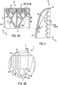
- FIG. 3A is a front view of the additively-manufactured self-supporting overhang structure shown in FIG. 2 .
- FIG. 3B is an enlargement showing detail of the ribs shown on FIG. 3A . Shown in FIGS. 3A - 3B are body 20, top 24, top extension 28, upper support structure 40, root point 42, branches 44a, 44b, 44c, 44d, gussets 46, and top vanes 48.
- the y-z coordinate axis is labeled in FIG. 3A .
- the z axis can be referred to as the vertical axis, being aligned with the build direction.
- the x axis (not labeled in FIG. 3A ) points out of the page.
- Branch radius R, vane spacing S, and vane thickness T are also labeled in FIG. 3B .
- Branch angle ⁇ is labeled in FIGS. 3A - 3B .
- the descriptions of body 20, top 24, top extension 28, upper support structure 40, root point 42, branches 44a, 44b, 44c, 44d, gussets 46, and top vanes 48 are substantially as provided above in regard to FIG. 2 .
- Interior edge 50 (not labeled in FIGS. 3A - 3B ) will be shown and described in more detail later in FIG. 4 .
- top vanes 48 are each oriented vertically (i.e., parallel to the vertical axis). In some embodiments, the orientation of one or more top vanes 48 can be different than illustrated.
- branch angle ⁇ describes the angle each branch 44 makes relative to the y axis (i.e., relative to the build plane).
- branch angle ⁇ is about 60 degrees, which allows for proper control of the additive manufacturing process in building upper support structure 40. Larger values of branch angle ⁇ provide for greater control of the additive manufacturing process, however they cause root point 42 to shift downward (i.e., toward bottom 22 as shown in FIG. 2 ), thereby adding greater mass to upper support structure 40. Accordingly, the selection of branch angle ⁇ can be made to optimize the balance between manufacturability and the overall size (i.e., mass) of upper support structure 40 for a particular additive manufacturing process, material selection, and design criteria for header 40.
- branch angle ⁇ can range from about 50 - 70 degrees. In other embodiments, branch angle ⁇ can range from about 45 - 75 degrees. In yet other embodiments, branch angle ⁇ can be greater than about 30 degrees, and can be as great as nearly 90 degrees. In some embodiments, branch angle ⁇ can be less than 30 degrees. Accordingly, all values of branch angle ⁇ are within the scope of the present disclosure.
- different branches 44 can have values of branch angle ⁇ that are different than others. As a non-limiting example, different branches 44 is a particular generation (e.g., branches 44a) can have different values of branch angle ⁇ . As another non-limiting example, the value of branch angle ⁇ in one generation (e.g., branches 44b) can be different from the value of branch angle ⁇ in another generation (e.g., branches 44c).
- each branch 44 has branch radius R, with labels being shown on branches 44c and 44d.
- Vane spacing S describes the opening between any two adjacent top vanes 48, and vane thickness T describes the thickness of any particular top vane 48.
- Branch radius R can also be referred to as the branch separation radius, and vane spacing S can also be referred to as the vane spacing interval.
- branch radius R helps reduce stress intensification that could otherwise occur at branches 44 (i.e., with sharp corners). Because header 14 (i.e., body 20) contains the system pressure of the working fluid, pressure stress can contribute to the stress intensification that can occur near branches 44.
- branch radius R can help mitigate the effect of pressure and thermal stress in header 14 from branches 44.
- Branch radius R can be expressed in terms of vane spacing S. In the illustrated embodiment, branch radius R is about 0.5 times vane spacing S. In some embodiments, branch radius R can range from about 0.2 - 0.5 times vane spacing S. In other embodiments, branch radius R can be less than 0.2 times vane spacing S. In the illustrated embodiment, vane spacing S is about 2 mm.
- vane spacing S can range from about 1.5 - 3 mm. In other embodiments, vane spacing S can range from about 0.1 - 5 mm. In yet other embodiments, vane spacing S can be less than 0.1 mm or greater than 5 mm. In the illustrated embodiment, vane thickness T is about 1 mm. In some embodiments, vane thickness T can range from about 0.7 - 2 mm. In other embodiments, vane thickness T can range from about 0.5 - 5 mm. In yet other embodiments, vane thickness T can be less than 0.5 mm or greater than 5 mm.
- branch radius R, vane spacing S, and vane thickness T can depend on several factors, with non-limiting examples including the material that header 14 is made of, the additive manufacturing process used to fabricate header 14, and the design pressure and temperature of header 14.
- header 14 is made of a metallic material. Accordingly, the selection of vane spacing S and vane thickness T can provide an adequate heat sink for forming top extension 28 during the additive manufacturing process.
- Upper support structure 40 can also be referred to as a trimmed branch structure. A benefit of a trimmed branch structure can be to provide an adequate heat sink during a laser powder bed fusion build process while reducing or minimizing added mass.
- upper support structure 40 is integral to header 14, there is not a need to add a temporary support structure for the build process that is later removed. This can allow for building an entirely closed structure, for example, as shown in FIG. 1 .
- metallic materials that can be used include nickel, aluminum, titanium, copper, iron, steel, cobalt, and all alloys that include these various metals.
- various alloys of INCONELTM can be used, with Inconel 625 and Inconel 718 being two exemplary alloy formulations.
- other nickel-based Superalloys can be used, with Haynes 282TM being an example.
- alloys of aluminum can be used.
- alloys of aluminum known as A205, A20XTM AlSi10Mg, and Aluminum 6061 can be used.
- the branchwork of gussets 46 that form upper support structure 40 have open spaces between adjacent gussets 46.
- a portion of the working fluid can flow along (i.e., through) the branchwork of gussets 46.
- Some of the working fluid flow can flow between adjacent top vanes 48. Accordingly, restrictions to fluid flow are reduced or avoided, and increased mass and associated mass discontinuities, geometric discontinuities, and stiffness discontinuities can also be reduced or avoided.
- upper support structure 40 can guide the flow of the working fluid in header 14 in some embodiments.
- FIG. 4 is a side view of upper support structure 40 shown in FIG. 2 . Shown in FIG. 4 are body 20, top 24, top extension 28, upper support structure 40, root point 42, and interior edge 50. The x-z coordinate axis is labeled in FIG. 4 . Interior edge angle ⁇ is also labeled in FIG. 4 . The descriptions of body 20, top 24, top extension 28, upper support structure 40, root point 42, and interior edge 50 are substantially as provided above in regard to FIG. 2 . Interior edge angle ⁇ describes the angle interior edge 50 makes relative to the x axis (i.e., relative to the build plane). In the illustrated embodiment, interior edge angle ⁇ is about 60 degrees, which allows for proper control of the additive manufacturing process in building upper support structure 40.
- interior edge angle ⁇ can range from about 50 - 70 degrees. In other embodiments, interior edge angle ⁇ can range from about 45 - 75 degrees. In yet other embodiments, interior edge angle ⁇ can be greater than about 30 degrees, and can be as great as nearly 90 degrees. In some embodiments, interior edge angle ⁇ can be less than 30 degrees. Accordingly, all values of interior edge angle ⁇ are within the scope of the present disclosure.
- An additively-manufactured heat exchanger header defining a build plane and a vertical axis, the vertical axis being orthogonal to the build plane and defining a build direction
- the additively-manufactured heat exchanger header comprising: a header body configured to at least partially contain a working fluid, the header body defining a middle region, an upper region, and a top extension; wherein: the upper region is oriented over the middle region relative to the vertical axis; and the top extension partially defines the fluid boundary and is oriented over the upper region; and an upper support structure disposed on the header body, the upper support structure comprising a branchwork of gussets rising upward and outward from a root point disposed in the middle region on the header body, the branchwork of gussets forming a plurality of top vanes, each supporting the top extension, the upper support structure defining an interior edge.
- the additively-manufactured heat exchanger header of the preceding paragraph can optionally include, additionally and/or alternatively, any one or more of the following features, configurations and/or additional components:
- a further embodiment of the foregoing additively-manufactured heat exchanger header wherein: the interior edge defines an interior edge angle relative to the build plane; the interior edge angle is greater than 30 degrees; the branchwork of gussets comprises a plurality of branches; each of the plurality of branches defines a branch angle; and the branch angle is greater than 30 degrees.
- a further embodiment of the foregoing additively-manufactured heat exchanger header wherein: the interior edge angle is between 45 - 75 degrees; and the branch angle is between 45 - 75 degrees.
- each of the plurality of top vanes defines a vane thickness; and the vane thickness is between 0.5 - 5 mm.
- a further embodiment of the foregoing additively-manufactured heat exchanger header wherein: two adjacent top vanes defines a vane spacing interval; and the vane spacing interval is between 0.1 - 5 mm.
- each of the plurality of top vanes defines a vane thickness; the vane thickness is between 0.7 - 2 mm; and the vane spacing interval is between 1.5 - 3 mm.
- the branchwork of gussets comprises a plurality of branches; two adjacent branches define a branch separation radius; and the branch separation radius is between 0.2 - 0.5 times the vane spacing interval.
- a further embodiment of the foregoing additively-manufactured heat exchanger header comprising nickel, aluminum, titanium, copper, iron, cobalt, and/or alloys thereof.
- a further embodiment of the foregoing additively-manufactured heat exchanger header comprising Inconel 625, Inconel 718, Haynes 282TM, A205, A20XTM, AlSi10Mg, or Aluminum 6061.
- a further embodiment of the foregoing additively-manufactured heat exchanger header further comprising: a bottom extension; and a lower region; wherein: the lower region is oriented under the middle region relative to the vertical axis; the bottom extension is oriented under the lower region; and the bottom extension partially defines the fluid boundary.
- a further embodiment of the foregoing additively-manufactured heat exchanger header further comprising one or more flow nozzles disposed on the header body, each of the one or more flow nozzles configured to port a working fluid into and/or out of the additively-manufactured heat exchanger header.
- a heat exchanger comprising the foregoing additively-manufactured heat exchanger header, wherein the heat exchanger is configured to: port a first fluid and a second fluid through the heat exchanger while maintaining isolation of the first fluid from the second fluid; and transfer heat between the first fluid and the second fluid.
- LPBF laser powder bed fusion
- the method of the preceding paragraph can optionally include, additionally and/or alternatively, any one or more of the following features, configurations and/or additional components:
- the interior edge defines an interior edge angle relative to the build plane; the interior edge angle is greater than 30 degrees; the branchwork of gussets comprises a plurality of branches; each of the plurality of branches defines a branch angle; and the branch angle is greater than 30 degrees.
- each of the plurality of top vanes defines a vane thickness; the vane thickness is between 0.5 - 5 mm; two adjacent top vanes defines a vane spacing interval; and the vane spacing interval is between 0.1 - 5 mm.
- the branchwork of gussets comprises a plurality of branches; two adjacent branches define a branch separation radius; and the branch separation radius is between 0.2 - 0.5 times the vane spacing interval.
Landscapes
- Engineering & Computer Science (AREA)
- Manufacturing & Machinery (AREA)
- Chemical & Material Sciences (AREA)
- Materials Engineering (AREA)
- Physics & Mathematics (AREA)
- Mechanical Engineering (AREA)
- Thermal Sciences (AREA)
- General Engineering & Computer Science (AREA)
- Geometry (AREA)
- Plasma & Fusion (AREA)
- Heat-Exchange Devices With Radiators And Conduit Assemblies (AREA)
Abstract
Description
- The present disclosure relates to heat exchangers, and more particularly, to a self-supporting additively-manufactured heat exchanger header that improves the manufacturability and performance of the heat exchanger.
- Heat exchangers are well known in the aviation arts and in other industries for providing a compact, low-weight, and highly-effective means of exchanging heat from a hot fluid to a cold fluid. Heat exchangers that operate at elevated temperatures often have short service lives and/or require increased maintenance as a result of high cyclic thermal stress. The stress is caused by multiple system and component factors including rapid flow and/or temperature transients, geometric discontinuities, stiffness discontinuities, mass discontinuities, and materials of construction. For example, inlet and outlet headers are typically pressure vessels that are welded or bolted to a heat exchanger core or matrix. Pressure requirements dictate the thickness of these manifolds, sometimes resulting in a relatively thick header attached to a thinner core matrix. This mismatch in thickness and mass, while acceptable for pressure loads, conflicts with the goal of avoiding discontinuities to limit thermal stress.
- Additive manufacturing can be used to build a heat exchanger core and headers as an integral unit, thereby overcoming some of aforementioned disadvantages. Moreover, the need to metallurgically attach headers to a heat exchanger core is avoided, thereby avoiding several possible disadvantages that can be associated with welding or brazing processes. In a typical additive manufacturing process, an integral heat exchanger core and header can be built up layer-by-layer against the direction of gravity. While many areas of a heat exchanger and header can be readily fabricated using additive manufacturing techniques, difficulty can occur in building the upper region of the headers, where an overhang must be fashioned. Massive internal support structures can be provided for additively-manufacturing the overhang, resulting in fluid flow restrictions, increased mass and the associated mass discontinuities, geometric discontinuities, and stiffness discontinuities. Accordingly, there is a need for a self-supporting additively-manufactured heat exchanger header that overcomes these disadvantages.
- An additively-manufactured heat exchanger header defines a build plane and a vertical axis defining a build direction that is orthogonal to the build plane. The additively-manufactured heat exchanger header includes a header body configured to at least partially contain a working fluid and an upper support structure on the header body. The upper support structure defines an interior edge and includes a branchwork of gussets rising upward and outward from a root point located in the middle region on the header body. The header body defines a middle region, an upper region, and a top extension. The branchwork of gussets forms a number of top vanes, each supporting the top extension. The upper region is oriented over the middle region relative to the vertical axis, and the top extension partially defines the fluid boundary and is oriented over the upper region.
- A method of using laser powder bed fusion (LPBF) to build a heat exchanger header defining a build plane and a vertical axis defining a build direction that is orthogonal to the build plane. The method includes building a header body configured to at least partially contain a working fluid, the header body defining a middle region, an upper region oriented over the middle region relative to the vertical axis, and a top extension that partially defines the fluid boundary and is oriented over the upper region, and building an upper support structure on the header body. The upper support structure includes a branchwork of gussets rising upward and outward from a root point located in the middle region on the header body, the branchwork of gussets forming a number of top vanes, each supporting the top extension. The header body and the upper support structure are built concurrently in the build direction.
-
-
FIG. 1 is a perspective view of an additively-manufactured heat exchanger. -
FIG. 2 is a perspective view showing the internal structure of an additively-manufactured header shown inFIG. 1 . -
FIG. 3A is front view of the additively-manufactured self-supporting overhang structure shown inFIG. 2 . -
FIG. 3B is an enlargement showing detail of the ribs shown onFIG. 3A . -
FIG. 4 is side view of the additively-manufactured self-supporting overhang structure shown inFIG. 2 . - The present disclosure is directed to an additively-manufactured heat exchanger header having a self-supporting design. For the sake of illustrating and describing the present disclosure, a self-supporting header is shown in an exemplary embodiment on a hot circuit of a heat exchanger core. Accordingly, the hot circuit of a heat exchanger is disclosed. It is to be appreciated that a heat exchanger utilizing the self-supporting header of the present embodiment also includes a cold circuit. In some embodiments, the cold circuit can also include inlet and outlet headers that can be similar to the self-supporting header of the present disclosure.
-
FIG. 1 is a perspective view of an additively-manufactured heat exchanger. Shown inFIG. 1 areheat exchanger 10, core 12,headers 14,nozzles 16, andflanges 18. The x-y-z coordinate axes are also labeled inFIG. 1 , with the x-y axes defining the additive-manufacturing (AM) build plane, and the z axis defining the additive-manufacturing build direction. During an additive-manufacturing process the build direction is upward, against gravity. Therefore,heat exchanger 10 depicted inFIG. 1 has been rotated 90 degrees following its manufacture (i.e., the z axis, in reference toheat exchanger 10, is oriented approximately in the horizontal direction as shown inFIG. 1 ).Heat exchanger 10 includes core 12 which transfers heat from one fluid to another while maintaining a fluid separation between the two fluid circuits. Heat will generally flow from the hot fluid to the cold fluid across the various components within core 12. Therefore, as used in this disclosure, "hot" will be used to describe the first fluid circuit and "cold" will be used to describe the second fluid circuit. The terms "hot" and "cold" are relative one to the other. As used in different embodiments,heat exchanger 10 can encounter temperatures ranging from near absolute zero (for example, in cryogenic distillation) to 1,000 deg. F (538 deg. C) or more (for example, in gas turbine engine systems and related components). Moreover, "hot" and "cold" are used in this disclosure as descriptive terms to refer to the various components that are associated with the respective first and second fluid circuits in the heat exchanger core, without implying that particular temperatures or a temperature relationship exists for those components during the manufacturing process of the heat exchanger core. - During operation of
heat exchanger 10, a hot fluid flows into and out of core 12 viaheaders 14, each having an associatednozzle 16 that terminates at aflange 18. Accordingly,flanges 18 can be connected to other fluid circuit components (not shown) to channel the hot fluid into and out ofheat exchanger 10. The hot and cold fluids can each be referred to as working fluids. Moreover, the hot fluid can be referred to as a first fluid, and the cold fluid can be referred to as a second fluid.Headers 14 can be referred to as additively-manufactured headers.Headers 14 can also be referred to as manifolds or as plenums. In the illustrated embodiment, heat exchanger 10 (i.e., including core 12,headers 14,nozzles 16, and flanges 18) is built as an integrated component using an additive-manufacturing process. Laser powder bed fusion (LPBF) is a non-limiting exemplary additive-manufacturing process that can be used to manufactureheat exchanger 10. Several advantages can result from additively-manufacturingheat exchanger 10 as an integral unit, including the avoidance of having to metallurgically attach separate headers onto a core, with resulting heat affected zones and mass discontinuities. Additive manufacturing also allows for more intricate features to be built intoheat exchanger 10, which can improve the thermal and/or hydrodynamic performance. However, as noted above, challenges in forming horizontal overhang structures must be overcome. As will be seen inFIG. 2 , the present disclosure eliminates the need to create a massive internal support structure underlying the overhang regions of an additively-manufactured header, thereby avoiding the associated restrictions to fluid flow, increased mass and associated mass discontinuities, geometric discontinuities, and stiffness discontinuities. -
FIG. 2 is a perspective view showing the internal structure ofheader 14 shown inFIG. 1 . Shown inFIG. 2 areheader 14,nozzle 16,body 20, bottom 22, top 24,bottom extension 26,top extension 28,lower region 30, middle region 32,upper region 34,upper support structure 40,root point 42,branches gussets 46,top vanes 48, andinterior edge 50.Header 14 can be eitherheader 14 shown onheat exchanger 10 inFIG. 1 . For ease of illustration,flange 18 is not shown onnozzle 16 inFIG. 2 . The x-y-z coordinate axes and the build direction are also labeled inFIG. 2 , with the x-y axes defining the additive manufacturing build plane and the z axis defining the build direction.Body 20 describes the outer structure of header 14 (i.e., not including upper support structure 40), thereby providing the pressure boundary when containing a working fluid (e.g., hot fluid). During an additive-manufacturing process, the build direction is upward against gravity (i.e., in the direction of the z axis), as described above in regard toFIG. 1 . Accordingly, the build direction proceeds from bottom 22 to top 24, beginning withbottom extension 26 and ending withtop extension 28.Top extension 28 can be described as an overhang structure, having a substantially horizontal orientation with respect to gravity (i.e., the z axis). Three regions can be defined on body 20:lower region 30, middle region 32, andupper region 34, as shown inFIG. 2 . It is known in the additive-manufacturing art that unsupported overhang structures are difficult to manufacture, and can result in sagging, dropout, and/or failure if an adequate underlying support structure is not provided. However, an additive manufacturing process readily lends itself to the fabrication of horizontal, vertical, and near-vertical structures. Accordingly, the portions ofheader 14 inlower region 30 and middle region 32 can be fabricated using known means. However, the fabrication of top extension 28 (i.e., neartop 24, in upper region 34), requires an underlying support structure.Upper support structure 40 provides a necessary supporting structure fortop extension 28, as will be described, while adding minimal mass toheader 14. -
Upper support structure 40 begins atroot point 42 in middle region 32 onbody 20, forming a branchwork ofgussets 46 that grow upward and outward during the fabrication process. Branches 44 describe the points where two ormore gussets 46 emerge from a starting point. In the embodiment shown inFIG. 2 , threegussets 46 rise upward fromroot point 42, diverging atbranch 44a. Accordingly,branch 44a can be referred to as a first generation branch. Similarly,branches 44b can be referred to as second generation branches,branches 44c can be referred to as third generation branches, andbranches 44d can be referred to as fourth generation branches. In the illustrated embodiment,branches 44d are the final generation of branches 44.Top vanes 48 are the final generation ofgussets 46 that grow upward from the final generation of branches 44 (i.e.,branches 44d), thereby supportingtop extension 28. Gussets 46 andtop vanes 48 forminterior edge 50, which will be shown and described in greater detail later, inFIG. 4 . Additional details ofupper support structure 40 will be shown and described later, inFIGS. 3A - 3B . Header 14 (i.e., manifold, plenum) can be modeled as a pressure vessel. As used in different embodiments,heat exchanger 10 can encounter pressures ranging from about 1 Atm. (14.7 psi, 101 kPa) up to 100 Atm. (1,470 psi, 10,100 kPa) or more. Accordingly, particularly in applications involving greater pressures,header 14 can be subjected to relatively high values of pressure force (i.e., pressure acting over a surface area thereupon applied), which can cause associated high values of associated tensile stress throughoutheader 14.Upper support structure 40 also provides reinforcement ofheader 14, thereby allowingheader 14 to accommodate a higher working pressure without increasing the overall thickness ofheader 14. Therefore,header 14 can be referred to as a self-supporting additively-manufactured heat exchanger header or as a self-supporting reinforced additively-manufactured heat exchanger header. In some embodiments, upper support structure provides stiffening ofheader 14 thereby improving the structural performance ofheader 14. Non-limiting examples of improved structural performance include improved performance during hydraulic and/or temperature transients, and dampening of flow-induced resonance. - Middle region 32 is defined as being the region on
body 20 whereroot point 42 begins, such thatupper support structure 40 grows intoupper region 34 to supporttop extension 28. The relative dimensions of lower, middle, andupper regions lower region 30 can be excluded so thatroot point 42 begins at or nearbottom extension 26. Accordingly, in these embodiments, upper support structure can cover most or all ofbody 20. - In the embodiment shown in
FIG. 2 , four generations of branches 44 are used to define the network oftop vanes 48 that supportstop extension 28. In some embodiments, fewer than four generations of branches 44 can be used. In other embodiments, five or more generations of branches 44 can be used. In the embodiment shown inFIG. 2 ,upper support structure 40 grows from asingle root point 42. In some embodiments, two or more root points 42 can be used, each supporting anupper support structure 40 that grows upward to a network oftop vanes 48. Accordingly, in some embodiments, two or more networks oftop vanes 48 can be used to supporttop extension 28. In the embodiment shown inFIG. 2 ,upper support structure 40 has left-right symmetry (i.e., relative to the z axis). In some embodiments, a non-symmetrical orientation ofgussets 46 can be used to formupper support structure 40. Any of the aforementioned other variations and embodiments can be combined together in a particular embodiment. For example, in a particular embodiment, two or moreupper support structures 40 can grow from an associatedroot point 42, each having a different number of generations of branches 44. -
FIG. 3A is a front view of the additively-manufactured self-supporting overhang structure shown inFIG. 2 .FIG. 3B is an enlargement showing detail of the ribs shown onFIG. 3A . Shown inFIGS. 3A - 3B arebody 20, top 24,top extension 28,upper support structure 40,root point 42,branches gussets 46, andtop vanes 48. The y-z coordinate axis is labeled inFIG. 3A . The z axis can be referred to as the vertical axis, being aligned with the build direction. The x axis (not labeled inFIG. 3A ) points out of the page. Branch radius R, vane spacing S, and vane thickness T are also labeled inFIG. 3B . Branch angle β is labeled inFIGS. 3A - 3B . The descriptions ofbody 20, top 24,top extension 28,upper support structure 40,root point 42,branches gussets 46, andtop vanes 48 are substantially as provided above in regard toFIG. 2 . Interior edge 50 (not labeled inFIGS. 3A - 3B ) will be shown and described in more detail later inFIG. 4 . In the illustrated embodiment,top vanes 48 are each oriented vertically (i.e., parallel to the vertical axis). In some embodiments, the orientation of one or moretop vanes 48 can be different than illustrated. - Referring again to
FIGS. 3A - 3B , branch angle β describes the angle each branch 44 makes relative to the y axis (i.e., relative to the build plane). In the illustrated embodiment, branch angle β is about 60 degrees, which allows for proper control of the additive manufacturing process in buildingupper support structure 40. Larger values of branch angle β provide for greater control of the additive manufacturing process, however they causeroot point 42 to shift downward (i.e., toward bottom 22 as shown inFIG. 2 ), thereby adding greater mass toupper support structure 40. Accordingly, the selection of branch angle β can be made to optimize the balance between manufacturability and the overall size (i.e., mass) ofupper support structure 40 for a particular additive manufacturing process, material selection, and design criteria forheader 40. In some embodiments, branch angle β can range from about 50 - 70 degrees. In other embodiments, branch angle β can range from about 45 - 75 degrees. In yet other embodiments, branch angle β can be greater than about 30 degrees, and can be as great as nearly 90 degrees. In some embodiments, branch angle β can be less than 30 degrees. Accordingly, all values of branch angle β are within the scope of the present disclosure. Moreover, different branches 44 can have values of branch angle β that are different than others. As a non-limiting example, different branches 44 is a particular generation (e.g.,branches 44a) can have different values of branch angle β. As another non-limiting example, the value of branch angle β in one generation (e.g.,branches 44b) can be different from the value of branch angle β in another generation (e.g.,branches 44c). - Referring again to
FIGS. 3A - 3B , each branch 44 has branch radius R, with labels being shown onbranches top vanes 48, and vane thickness T describes the thickness of any particulartop vane 48. Branch radius R can also be referred to as the branch separation radius, and vane spacing S can also be referred to as the vane spacing interval. In the illustrated embodiment, of branch radius R helps reduce stress intensification that could otherwise occur at branches 44 (i.e., with sharp corners). Because header 14 (i.e., body 20) contains the system pressure of the working fluid, pressure stress can contribute to the stress intensification that can occur near branches 44. Moreover, temperature transients can cause thermal stress that can contribute to the stress intensification that can occur near branches 44. Uncontrolled stress intensification can result in fatigue ofheader 14, includingbody 20 and/orupper support structure 40, which can reduce the service life ofheat exchanger 10. Accordingly, branch radius R can help mitigate the effect of pressure and thermal stress inheader 14 from branches 44. Branch radius R can be expressed in terms of vane spacing S. In the illustrated embodiment, branch radius R is about 0.5 times vane spacing S. In some embodiments, branch radius R can range from about 0.2 - 0.5 times vane spacing S. In other embodiments, branch radius R can be less than 0.2 times vane spacing S. In the illustrated embodiment, vane spacing S is about 2 mm. In some embodiments, vane spacing S can range from about 1.5 - 3 mm. In other embodiments, vane spacing S can range from about 0.1 - 5 mm. In yet other embodiments, vane spacing S can be less than 0.1 mm or greater than 5 mm. In the illustrated embodiment, vane thickness T is about 1 mm. In some embodiments, vane thickness T can range from about 0.7 - 2 mm. In other embodiments, vane thickness T can range from about 0.5 - 5 mm. In yet other embodiments, vane thickness T can be less than 0.5 mm or greater than 5 mm. - The selection of values for branch radius R, vane spacing S, and vane thickness T can depend on several factors, with non-limiting examples including the material that
header 14 is made of, the additive manufacturing process used to fabricateheader 14, and the design pressure and temperature ofheader 14. In the illustrated embodiment,header 14 is made of a metallic material. Accordingly, the selection of vane spacing S and vane thickness T can provide an adequate heat sink for formingtop extension 28 during the additive manufacturing process.Upper support structure 40 can also be referred to as a trimmed branch structure. A benefit of a trimmed branch structure can be to provide an adequate heat sink during a laser powder bed fusion build process while reducing or minimizing added mass. Becauseupper support structure 40 is integral toheader 14, there is not a need to add a temporary support structure for the build process that is later removed. This can allow for building an entirely closed structure, for example, as shown inFIG. 1 . Non-limiting examples of metallic materials that can be used include nickel, aluminum, titanium, copper, iron, steel, cobalt, and all alloys that include these various metals. In some embodiments, various alloys of INCONEL™ can be used, with Inconel 625 and Inconel 718 being two exemplary alloy formulations. In other embodiments, other nickel-based Superalloys can be used, with Haynes 282™ being an example. In yet other embodiments, alloys of aluminum can be used. For example, alloys of aluminum known as A205, A20X™ AlSi10Mg, and Aluminum 6061 can be used. - As shown and described above in regard to
FIGS. 3A - 3B , the branchwork ofgussets 46 that formupper support structure 40 have open spaces betweenadjacent gussets 46. When a working fluid is flowing throughheader 14, a portion of the working fluid can flow along (i.e., through) the branchwork ofgussets 46. Some of the working fluid flow can flow between adjacenttop vanes 48. Accordingly, restrictions to fluid flow are reduced or avoided, and increased mass and associated mass discontinuities, geometric discontinuities, and stiffness discontinuities can also be reduced or avoided. Moreover,upper support structure 40 can guide the flow of the working fluid inheader 14 in some embodiments. -
FIG. 4 is a side view ofupper support structure 40 shown inFIG. 2 . Shown inFIG. 4 arebody 20, top 24,top extension 28,upper support structure 40,root point 42, andinterior edge 50. The x-z coordinate axis is labeled inFIG. 4 . Interior edge angle α is also labeled inFIG. 4 . The descriptions ofbody 20, top 24,top extension 28,upper support structure 40,root point 42, andinterior edge 50 are substantially as provided above in regard toFIG. 2 . Interior edge angle α describes the angleinterior edge 50 makes relative to the x axis (i.e., relative to the build plane). In the illustrated embodiment, interior edge angle α is about 60 degrees, which allows for proper control of the additive manufacturing process in buildingupper support structure 40. Larger values of interior edge angle α provide for greater control of the additive manufacturing process, however they causeroot point 42 to shift downward (i.e., toward bottom 22 as shown inFIG. 2 ), thereby adding greater mass toupper support structure 40. Accordingly, the selection of interior edge angle α can be made to optimize the balance between manufacturability and the overall size (i.e., mass) ofupper support structure 40 for a particular additive manufacturing process, material selection, and design criteria forheader 40. In some embodiments, interior edge angle α can range from about 50 - 70 degrees. In other embodiments, interior edge angle α can range from about 45 - 75 degrees. In yet other embodiments, interior edge angle α can be greater than about 30 degrees, and can be as great as nearly 90 degrees. In some embodiments, interior edge angle α can be less than 30 degrees. Accordingly, all values of interior edge angle α are within the scope of the present disclosure. - The following are non-exclusive descriptions of possible embodiments of the present invention.
- An additively-manufactured heat exchanger header defining a build plane and a vertical axis, the vertical axis being orthogonal to the build plane and defining a build direction, the additively-manufactured heat exchanger header comprising: a header body configured to at least partially contain a working fluid, the header body defining a middle region, an upper region, and a top extension; wherein: the upper region is oriented over the middle region relative to the vertical axis; and the top extension partially defines the fluid boundary and is oriented over the upper region; and an upper support structure disposed on the header body, the upper support structure comprising a branchwork of gussets rising upward and outward from a root point disposed in the middle region on the header body, the branchwork of gussets forming a plurality of top vanes, each supporting the top extension, the upper support structure defining an interior edge.
- The additively-manufactured heat exchanger header of the preceding paragraph can optionally include, additionally and/or alternatively, any one or more of the following features, configurations and/or additional components:
- A further embodiment of the foregoing additively-manufactured heat exchanger header, wherein: the interior edge defines an interior edge angle relative to the build plane; the interior edge angle is greater than 30 degrees; the branchwork of gussets comprises a plurality of branches; each of the plurality of branches defines a branch angle; and the branch angle is greater than 30 degrees.
- A further embodiment of the foregoing additively-manufactured heat exchanger header, wherein: the interior edge angle is between 45 - 75 degrees; and the branch angle is between 45 - 75 degrees.
- A further embodiment of the foregoing additively-manufactured heat exchanger header, wherein: each of the plurality of top vanes defines a vane thickness; and the vane thickness is between 0.5 - 5 mm.
- A further embodiment of the foregoing additively-manufactured heat exchanger header, wherein: two adjacent top vanes defines a vane spacing interval; and the vane spacing interval is between 0.1 - 5 mm.
- A further embodiment of the foregoing additively-manufactured heat exchanger header, wherein: each of the plurality of top vanes defines a vane thickness; the vane thickness is between 0.7 - 2 mm; and the vane spacing interval is between 1.5 - 3 mm.
- A further embodiment of the foregoing additively-manufactured heat exchanger header, wherein the plurality of top vanes is configured to provide a heat sink for the top extension during an additive manufacturing process.
- A further embodiment of the foregoing additively-manufactured heat exchanger header, wherein each of the plurality of top vanes is parallel to the vertical axis.
- A further embodiment of the foregoing additively-manufactured heat exchanger header, wherein: the branchwork of gussets comprises a plurality of branches; two adjacent branches define a branch separation radius; and the branch separation radius is between 0.2 - 0.5 times the vane spacing interval.
- A further embodiment of the foregoing additively-manufactured heat exchanger header, comprising nickel, aluminum, titanium, copper, iron, cobalt, and/or alloys thereof.
- A further embodiment of the foregoing additively-manufactured heat exchanger header, comprising Inconel 625, Inconel 718, Haynes 282™, A205, A20X™, AlSi10Mg, or Aluminum 6061.
- A further embodiment of the foregoing additively-manufactured heat exchanger header, wherein the branchwork of gussets comprises three or more generations of branches.
- A further embodiment of the foregoing additively-manufactured heat exchanger header, further comprising: a bottom extension; and a lower region; wherein: the lower region is oriented under the middle region relative to the vertical axis; the bottom extension is oriented under the lower region; and the bottom extension partially defines the fluid boundary.
- A further embodiment of the foregoing additively-manufactured heat exchanger header, further comprising one or more flow nozzles disposed on the header body, each of the one or more flow nozzles configured to port a working fluid into and/or out of the additively-manufactured heat exchanger header.
- A heat exchanger comprising the foregoing additively-manufactured heat exchanger header, wherein the heat exchanger is configured to: port a first fluid and a second fluid through the heat exchanger while maintaining isolation of the first fluid from the second fluid; and transfer heat between the first fluid and the second fluid.
- A method of using laser powder bed fusion (LPBF) to build a heat exchanger header defining a build plane and a vertical axis, the vertical axis being orthogonal to the build plane and defining a build direction, the method comprising: building a header body configured to at least partially contain a working fluid, the header body defining a middle region, an upper region, and a top extension; wherein: the upper region is oriented over the middle region relative to the vertical axis; and the top extension partially defines the fluid boundary and is oriented over the upper region; and building an upper support structure on the header body, the upper support structure comprising a branchwork of gussets rising upward and outward from a root point disposed in the middle region on the header body, the branchwork of gussets forming a plurality of top vanes, each supporting the top extension, the upper support structure defining an interior edge; wherein the header body and the upper support structure are built concurrently in the build direction.
- The method of the preceding paragraph can optionally include, additionally and/or alternatively, any one or more of the following features, configurations and/or additional components:
- A further embodiment of the foregoing method, wherein: the interior edge defines an interior edge angle relative to the build plane; the interior edge angle is greater than 30 degrees; the branchwork of gussets comprises a plurality of branches; each of the plurality of branches defines a branch angle; and the branch angle is greater than 30 degrees.
- A further embodiment of the foregoing method, wherein: the interior edge angle is between 45 - 75 degrees; and the branch angle is between 45 - 75 degrees.
- A further embodiment of the foregoing method, wherein: each of the plurality of top vanes defines a vane thickness; the vane thickness is between 0.5 - 5 mm; two adjacent top vanes defines a vane spacing interval; and the vane spacing interval is between 0.1 - 5 mm.
- A further embodiment of the foregoing method, wherein: the branchwork of gussets comprises a plurality of branches; two adjacent branches define a branch separation radius; and the branch separation radius is between 0.2 - 0.5 times the vane spacing interval.
- While the invention has been described with reference to an exemplary embodiment(s), it will be understood by those skilled in the art that various changes may be made and equivalents may be substituted for elements thereof without departing from the scope of the invention. In addition, many modifications may be made to adapt a particular situation or material to the teachings of the invention without departing from the essential scope thereof. Therefore, it is intended that the invention not be limited to the particular embodiment(s) disclosed, but that the invention will include all embodiments falling within the scope of the appended claims.
Claims (15)
- An additively-manufactured heat exchanger header defining a build plane and a vertical axis, the vertical axis being orthogonal to the build plane and defining a build direction, the additively-manufactured heat exchanger header comprising:a header body (20) configured to at least partially contain a working fluid, the header body defining a middle region (32), an upper region (34), and a top extension (28);
wherein:the upper region is oriented over the middle region relative to the vertical axis; andthe top extension partially defines the fluid boundary and is oriented over the upper region; andan upper support structure (40) disposed on the header body, the upper support structure comprising a branchwork (44, 46) of gussets rising upward and outward from a root point (42) disposed in the middle region on the header body, the branchwork of gussets forming a plurality of top vanes (48), each supporting the top extension, the upper support structure defining an interior edge (50). - The additively-manufactured heat exchanger header of claim 1, wherein:the interior edge defines an interior edge angle relative to the build plane;the interior edge angle is greater than 30 degrees;the branchwork of gussets comprises a plurality of branches;each of the plurality of branches defines a branch angle; andthe branch angle is greater than 30 degrees, and optionally wherein:the interior edge angle is between 45 - 75 degrees; andthe branch angle is between 45 - 75 degrees.
- The additively-manufactured heat exchanger header of claim 1 or 2, wherein:each of the plurality of top vanes defines a vane thickness; andthe vane thickness is between 0.5 - 5 mm.
- The additively-manufactured heat exchanger header of any preceding claim, wherein:two adjacent top vanes defines a vane spacing interval; andthe vane spacing interval is between 0.1 - 5 mm, and optionally wherein:each of the plurality of top vanes defines a vane thickness;the vane thickness is between 0.7 - 2 mm; andthe vane spacing interval is between 1.5 - 3 mm.
- The additively-manufactured heat exchanger header of any preceding claim, wherein the plurality of top vanes is configured to provide a heat sink for the top extension during an additive manufacturing process.
- The additively-manufactured heat exchanger header of any preceding claim, wherein each of the plurality of top vanes is parallel to the vertical axis.
- The additively-manufactured heat exchanger header of claim 4, wherein:the branchwork of gussets comprises a plurality of branches;two adjacent branches define a branch separation radius; andthe branch separation radius is between 0.2 - 0.5 times the vane spacing interval.
- The additively-manufactured heat exchanger header of any preceding claim, comprising nickel, aluminum, titanium, copper, iron, cobalt, and/or alloys thereof, and optionally comprising Inconel 625, Inconel 718, Haynes 282™, A205, A20X™, AlSi10Mg, or Aluminum 6061.
- The additively-manufactured heat exchanger header of any preceding claim, wherein the branchwork of gussets comprises three or more generations of branches.
- The additively-manufactured heat exchanger header of any preceding claim, further comprising:a bottom extension (26); anda lower region (30);wherein:the lower region is oriented under the middle region relative to the vertical axis;the bottom extension is oriented under the lower region; andthe bottom extension partially defines the fluid boundary.
- The additively-manufactured heat exchanger header of any preceding claim, further comprising one or more flow nozzles disposed on the header body, each of the one or more flow nozzles configured to port a working fluid into and/or out of the additively-manufactured heat exchanger header.
- A heat exchanger comprising the additively-manufactured heat exchanger header of any preceding claim, the heat exchanger configured to:port a first fluid and a second fluid through the heat exchanger while maintaining isolation of the first fluid from the second fluid; andtransfer heat between the first fluid and the second fluid.
- A method of using laser powder bed fusion, LPBF, to build a heat exchanger header defining a build plane and a vertical axis, the vertical axis being orthogonal to the build plane and defining a build direction, the method comprising:building a header body configured to at least partially contain a working fluid, the header body defining a middle region, an upper region, and a top extension;
wherein:the upper region is oriented over the middle region relative to the vertical axis; andthe top extension partially defines the fluid boundary and is oriented over the upper region; andbuilding an upper support structure on the header body, the upper support structure comprising a branchwork of gussets rising upward and outward from a root point disposed in the middle region on the header body, the branchwork of gussets forming a plurality of top vanes, each supporting the top extension, the upper support structure defining an interior edge;wherein the header body and the upper support structure are built concurrently in the build direction. - The method of claim 13, wherein:the interior edge defines an interior edge angle relative to the build plane;the interior edge angle is greater than 30 degrees;the branchwork of gussets comprises a plurality of branches;each of the plurality of branches defines a branch angle; andthe branch angle is greater than 30 degrees, and optionally wherein:the interior edge angle is between 45 - 75 degrees; andthe branch angle is between 45 - 75 degrees.
- The method of claim 13 or 14, wherein:each of the plurality of top vanes defines a vane thickness;the vane thickness is between 0.5 - 5 mm;two adjacent top vanes defines a vane spacing interval; andthe vane spacing interval is between 0.1 - 5 mm, and optionally wherein:the branchwork of gussets comprises a plurality of branches;two adjacent branches define a branch separation radius; andthe branch separation radius is between 0.2 - 0.5 times the vane spacing interval.
Applications Claiming Priority (1)
| Application Number | Priority Date | Filing Date | Title |
|---|---|---|---|
| US16/684,464 US11397062B2 (en) | 2019-11-14 | 2019-11-14 | Self-supporting additively-manufactured heat exchanger header |
Publications (2)
| Publication Number | Publication Date |
|---|---|
| EP3822079A1 true EP3822079A1 (en) | 2021-05-19 |
| EP3822079B1 EP3822079B1 (en) | 2023-07-05 |
Family
ID=73452079
Family Applications (1)
| Application Number | Title | Priority Date | Filing Date |
|---|---|---|---|
| EP20207805.1A Active EP3822079B1 (en) | 2019-11-14 | 2020-11-16 | Self-supporting additively-manufactured heat exchanger header |
Country Status (2)
| Country | Link |
|---|---|
| US (1) | US11397062B2 (en) |
| EP (1) | EP3822079B1 (en) |
Cited By (1)
| Publication number | Priority date | Publication date | Assignee | Title |
|---|---|---|---|---|
| EP3904819A1 (en) * | 2020-04-27 | 2021-11-03 | Hamilton Sundstrand Corporation | Heat exchanger header fabricated with integral flange using additive metal process |
Families Citing this family (2)
| Publication number | Priority date | Publication date | Assignee | Title |
|---|---|---|---|---|
| US11493286B1 (en) | 2021-10-12 | 2022-11-08 | Hamilton Sundstrand Corporation | Header for high-pressure heat exchanger |
| US12578145B2 (en) | 2023-08-22 | 2026-03-17 | Hamilton Sundstrand Corporation | Heat exchanger core geometries used as support material and fluid connectivity passages for heat exchanger headering |
Citations (3)
| Publication number | Priority date | Publication date | Assignee | Title |
|---|---|---|---|---|
| US20170146305A1 (en) * | 2015-11-24 | 2017-05-25 | Hamilton Sundstrand Corporation | Header for heat exchanger |
| US20180345425A1 (en) * | 2017-05-30 | 2018-12-06 | Ge Avio S.R.L. | Additively manufactured heat exchanger |
| US20190285364A1 (en) * | 2018-03-16 | 2019-09-19 | Hamilton Sundstrand Corporation | Plate fin heat exchanger flexible manifold structure |
Family Cites Families (16)
| Publication number | Priority date | Publication date | Assignee | Title |
|---|---|---|---|---|
| US6786275B2 (en) * | 2002-05-23 | 2004-09-07 | Valeo Engine Cooling | Heat exchanger header assembly |
| WO2008008710A1 (en) * | 2006-07-08 | 2008-01-17 | Modine Manufacturing Company | Heat exchanger and method of manufacturing the same |
| ES2376681B1 (en) * | 2008-01-10 | 2013-01-24 | Modine Manufacturing Company | HEAT EXCHANGER. |
| US8506242B2 (en) * | 2010-05-04 | 2013-08-13 | Brayton Energy Canada, Inc. | Method of making a heat exchange component using wire mesh screens |
| US9200855B2 (en) * | 2012-03-06 | 2015-12-01 | Honeywell International Inc. | Tubular heat exchange systems |
| US9976815B1 (en) | 2014-02-20 | 2018-05-22 | Hrl Laboratories, Llc | Heat exchangers made from additively manufactured sacrificial templates |
| US10995996B2 (en) * | 2014-10-07 | 2021-05-04 | Unison Industries, Llc | Multi-branch furcating flow heat exchanger |
| US20180045471A1 (en) * | 2015-03-05 | 2018-02-15 | Linde Aktiengesellschaft | 3d-printed heating surface element for a plate heat exchanger |
| US10089416B1 (en) | 2015-03-12 | 2018-10-02 | Stratasys, Inc. | Self-supporting internal passageways for powder metal additive manufacturing |
| US10371462B2 (en) | 2015-09-21 | 2019-08-06 | Lockheed Martin Corporation | Integrated multi-chamber heat exchanger |
| US20170089643A1 (en) * | 2015-09-25 | 2017-03-30 | Westinghouse Electric Company, Llc. | Heat Exchanger |
| US11530878B2 (en) * | 2016-04-07 | 2022-12-20 | Hamilton Sundstrand Corporation | Spiral tube heat exchanger |
| WO2017179587A1 (en) | 2016-04-13 | 2017-10-19 | 三菱重工業株式会社 | Support member for additive manufacturing, production method and production device for three-dimensional object by additive manufacturing, object model creation device, control device, and manufacturing method for object |
| US10682734B2 (en) | 2016-06-08 | 2020-06-16 | Raytheon Company | Internal cavity support methodology for ultrasonic additive manufacturing |
| WO2019060563A1 (en) | 2017-09-20 | 2019-03-28 | Additive Rocket Corporation | Additive manufacturing constructs and processes for their manufacture |
| EP3904819B1 (en) * | 2020-04-27 | 2023-09-27 | Hamilton Sundstrand Corporation | Heat exchanger header fabricated with integral flange using additive metal process |
-
2019
- 2019-11-14 US US16/684,464 patent/US11397062B2/en active Active
-
2020
- 2020-11-16 EP EP20207805.1A patent/EP3822079B1/en active Active
Patent Citations (3)
| Publication number | Priority date | Publication date | Assignee | Title |
|---|---|---|---|---|
| US20170146305A1 (en) * | 2015-11-24 | 2017-05-25 | Hamilton Sundstrand Corporation | Header for heat exchanger |
| US20180345425A1 (en) * | 2017-05-30 | 2018-12-06 | Ge Avio S.R.L. | Additively manufactured heat exchanger |
| US20190285364A1 (en) * | 2018-03-16 | 2019-09-19 | Hamilton Sundstrand Corporation | Plate fin heat exchanger flexible manifold structure |
Cited By (2)
| Publication number | Priority date | Publication date | Assignee | Title |
|---|---|---|---|---|
| EP3904819A1 (en) * | 2020-04-27 | 2021-11-03 | Hamilton Sundstrand Corporation | Heat exchanger header fabricated with integral flange using additive metal process |
| US11761717B2 (en) | 2020-04-27 | 2023-09-19 | Hamilton Sundstrand Corporation | Heat exchanger header fabricated with integral flange using additive metal process |
Also Published As
| Publication number | Publication date |
|---|---|
| US20210148655A1 (en) | 2021-05-20 |
| EP3822079B1 (en) | 2023-07-05 |
| US11397062B2 (en) | 2022-07-26 |
Similar Documents
| Publication | Publication Date | Title |
|---|---|---|
| EP3719432B1 (en) | Heat exchanger fractal splitter | |
| US10801790B2 (en) | Plate fin heat exchanger flexible manifold structure | |
| EP3822079B1 (en) | Self-supporting additively-manufactured heat exchanger header | |
| EP3825638B1 (en) | Integrated horn structures for heat exchanger headers | |
| US12209822B2 (en) | Heat exchangers having a three-dimensional lattice structure | |
| US11835304B2 (en) | Heat exchanger with stacked flow channel modules | |
| EP3410054B1 (en) | Additively manufactured heat exchanger | |
| EP3705830B1 (en) | Circular core for heat exchangers | |
| US10619934B2 (en) | Plate heat exchanger comprising structural reinforcements for a turbine engine | |
| US10443959B2 (en) | Integral heat exchanger manifold guide vanes and supports | |
| US7871041B2 (en) | System, method, and apparatus for leading edge structures and direct manufacturing thereof | |
| US20200016704A1 (en) | Heat Exchangers Having a Three-Dimensional Lattice Structure with a Rounded Unit Cell Entrance and Methods of Forming Rounded Unit Cell Entrances in a Three-Dimensional Lattice Structure of a Heat Exchanger | |
| JP2008286437A (en) | Heat exchanger | |
| EP4389423B1 (en) | Heat exchanger mount with internal flow passage | |
| JP6824557B2 (en) | Heat exchanger assembly | |
| EP4446686A1 (en) | Additively manufactured heat exchanger with multiple mixtures of materials | |
| EP3324027B1 (en) | Staged high temperature heat exchanger | |
| EP3653984B1 (en) | Plate fin heat exchanger flexible manifold structure | |
| US20250334339A1 (en) | Additively manufactured heat exchanger | |
| US20260092748A1 (en) | Additively manufactured heat exchanger supports and method of manufacture | |
| EP3662221A1 (en) | Heat exchanger |
Legal Events
| Date | Code | Title | Description |
|---|---|---|---|
| PUAI | Public reference made under article 153(3) epc to a published international application that has entered the european phase |
Free format text: ORIGINAL CODE: 0009012 |
|
| STAA | Information on the status of an ep patent application or granted ep patent |
Free format text: STATUS: THE APPLICATION HAS BEEN PUBLISHED |
|
| AK | Designated contracting states |
Kind code of ref document: A1 Designated state(s): AL AT BE BG CH CY CZ DE DK EE ES FI FR GB GR HR HU IE IS IT LI LT LU LV MC MK MT NL NO PL PT RO RS SE SI SK SM TR |
|
| STAA | Information on the status of an ep patent application or granted ep patent |
Free format text: STATUS: REQUEST FOR EXAMINATION WAS MADE |
|
| 17P | Request for examination filed |
Effective date: 20211119 |
|
| RBV | Designated contracting states (corrected) |
Designated state(s): AL AT BE BG CH CY CZ DE DK EE ES FI FR GB GR HR HU IE IS IT LI LT LU LV MC MK MT NL NO PL PT RO RS SE SI SK SM TR |
|
| GRAP | Despatch of communication of intention to grant a patent |
Free format text: ORIGINAL CODE: EPIDOSNIGR1 |
|
| STAA | Information on the status of an ep patent application or granted ep patent |
Free format text: STATUS: GRANT OF PATENT IS INTENDED |
|
| RIC1 | Information provided on ipc code assigned before grant |
Ipc: B33Y 80/00 20150101ALI20230117BHEP Ipc: F28F 9/02 20060101ALI20230117BHEP Ipc: B33Y 10/00 20150101AFI20230117BHEP |
|
| INTG | Intention to grant announced |
Effective date: 20230203 |
|
| GRAS | Grant fee paid |
Free format text: ORIGINAL CODE: EPIDOSNIGR3 |
|
| GRAA | (expected) grant |
Free format text: ORIGINAL CODE: 0009210 |
|
| STAA | Information on the status of an ep patent application or granted ep patent |
Free format text: STATUS: THE PATENT HAS BEEN GRANTED |
|
| AK | Designated contracting states |
Kind code of ref document: B1 Designated state(s): AL AT BE BG CH CY CZ DE DK EE ES FI FR GB GR HR HU IE IS IT LI LT LU LV MC MK MT NL NO PL PT RO RS SE SI SK SM TR |
|
| REG | Reference to a national code |
Ref country code: CH Ref legal event code: EP |
|
| REG | Reference to a national code |
Ref country code: AT Ref legal event code: REF Ref document number: 1584498 Country of ref document: AT Kind code of ref document: T Effective date: 20230715 |
|
| REG | Reference to a national code |
Ref country code: DE Ref legal event code: R096 Ref document number: 602020013258 Country of ref document: DE |
|
| REG | Reference to a national code |
Ref country code: IE Ref legal event code: FG4D |
|
| REG | Reference to a national code |
Ref country code: LT Ref legal event code: MG9D |
|
| REG | Reference to a national code |
Ref country code: NL Ref legal event code: MP Effective date: 20230705 |
|
| REG | Reference to a national code |
Ref country code: AT Ref legal event code: MK05 Ref document number: 1584498 Country of ref document: AT Kind code of ref document: T Effective date: 20230705 |
|
| PG25 | Lapsed in a contracting state [announced via postgrant information from national office to epo] |
Ref country code: NL Free format text: LAPSE BECAUSE OF FAILURE TO SUBMIT A TRANSLATION OF THE DESCRIPTION OR TO PAY THE FEE WITHIN THE PRESCRIBED TIME-LIMIT Effective date: 20230705 |
|
| PG25 | Lapsed in a contracting state [announced via postgrant information from national office to epo] |
Ref country code: GR Free format text: LAPSE BECAUSE OF FAILURE TO SUBMIT A TRANSLATION OF THE DESCRIPTION OR TO PAY THE FEE WITHIN THE PRESCRIBED TIME-LIMIT Effective date: 20231006 |
|
| PG25 | Lapsed in a contracting state [announced via postgrant information from national office to epo] |
Ref country code: ES Free format text: LAPSE BECAUSE OF FAILURE TO SUBMIT A TRANSLATION OF THE DESCRIPTION OR TO PAY THE FEE WITHIN THE PRESCRIBED TIME-LIMIT Effective date: 20230705 |
|
| PG25 | Lapsed in a contracting state [announced via postgrant information from national office to epo] |
Ref country code: IS Free format text: LAPSE BECAUSE OF FAILURE TO SUBMIT A TRANSLATION OF THE DESCRIPTION OR TO PAY THE FEE WITHIN THE PRESCRIBED TIME-LIMIT Effective date: 20231105 |
|
| PG25 | Lapsed in a contracting state [announced via postgrant information from national office to epo] |
Ref country code: SE Free format text: LAPSE BECAUSE OF FAILURE TO SUBMIT A TRANSLATION OF THE DESCRIPTION OR TO PAY THE FEE WITHIN THE PRESCRIBED TIME-LIMIT Effective date: 20230705 Ref country code: RS Free format text: LAPSE BECAUSE OF FAILURE TO SUBMIT A TRANSLATION OF THE DESCRIPTION OR TO PAY THE FEE WITHIN THE PRESCRIBED TIME-LIMIT Effective date: 20230705 Ref country code: PT Free format text: LAPSE BECAUSE OF FAILURE TO SUBMIT A TRANSLATION OF THE DESCRIPTION OR TO PAY THE FEE WITHIN THE PRESCRIBED TIME-LIMIT Effective date: 20231106 Ref country code: NO Free format text: LAPSE BECAUSE OF FAILURE TO SUBMIT A TRANSLATION OF THE DESCRIPTION OR TO PAY THE FEE WITHIN THE PRESCRIBED TIME-LIMIT Effective date: 20231005 Ref country code: LV Free format text: LAPSE BECAUSE OF FAILURE TO SUBMIT A TRANSLATION OF THE DESCRIPTION OR TO PAY THE FEE WITHIN THE PRESCRIBED TIME-LIMIT Effective date: 20230705 Ref country code: LT Free format text: LAPSE BECAUSE OF FAILURE TO SUBMIT A TRANSLATION OF THE DESCRIPTION OR TO PAY THE FEE WITHIN THE PRESCRIBED TIME-LIMIT Effective date: 20230705 Ref country code: IS Free format text: LAPSE BECAUSE OF FAILURE TO SUBMIT A TRANSLATION OF THE DESCRIPTION OR TO PAY THE FEE WITHIN THE PRESCRIBED TIME-LIMIT Effective date: 20231105 Ref country code: HR Free format text: LAPSE BECAUSE OF FAILURE TO SUBMIT A TRANSLATION OF THE DESCRIPTION OR TO PAY THE FEE WITHIN THE PRESCRIBED TIME-LIMIT Effective date: 20230705 Ref country code: GR Free format text: LAPSE BECAUSE OF FAILURE TO SUBMIT A TRANSLATION OF THE DESCRIPTION OR TO PAY THE FEE WITHIN THE PRESCRIBED TIME-LIMIT Effective date: 20231006 Ref country code: FI Free format text: LAPSE BECAUSE OF FAILURE TO SUBMIT A TRANSLATION OF THE DESCRIPTION OR TO PAY THE FEE WITHIN THE PRESCRIBED TIME-LIMIT Effective date: 20230705 Ref country code: ES Free format text: LAPSE BECAUSE OF FAILURE TO SUBMIT A TRANSLATION OF THE DESCRIPTION OR TO PAY THE FEE WITHIN THE PRESCRIBED TIME-LIMIT Effective date: 20230705 Ref country code: AT Free format text: LAPSE BECAUSE OF FAILURE TO SUBMIT A TRANSLATION OF THE DESCRIPTION OR TO PAY THE FEE WITHIN THE PRESCRIBED TIME-LIMIT Effective date: 20230705 |
|
| PG25 | Lapsed in a contracting state [announced via postgrant information from national office to epo] |
Ref country code: PL Free format text: LAPSE BECAUSE OF FAILURE TO SUBMIT A TRANSLATION OF THE DESCRIPTION OR TO PAY THE FEE WITHIN THE PRESCRIBED TIME-LIMIT Effective date: 20230705 |
|
| REG | Reference to a national code |
Ref country code: DE Ref legal event code: R097 Ref document number: 602020013258 Country of ref document: DE |
|
| PG25 | Lapsed in a contracting state [announced via postgrant information from national office to epo] |
Ref country code: SM Free format text: LAPSE BECAUSE OF FAILURE TO SUBMIT A TRANSLATION OF THE DESCRIPTION OR TO PAY THE FEE WITHIN THE PRESCRIBED TIME-LIMIT Effective date: 20230705 Ref country code: RO Free format text: LAPSE BECAUSE OF FAILURE TO SUBMIT A TRANSLATION OF THE DESCRIPTION OR TO PAY THE FEE WITHIN THE PRESCRIBED TIME-LIMIT Effective date: 20230705 Ref country code: EE Free format text: LAPSE BECAUSE OF FAILURE TO SUBMIT A TRANSLATION OF THE DESCRIPTION OR TO PAY THE FEE WITHIN THE PRESCRIBED TIME-LIMIT Effective date: 20230705 Ref country code: DK Free format text: LAPSE BECAUSE OF FAILURE TO SUBMIT A TRANSLATION OF THE DESCRIPTION OR TO PAY THE FEE WITHIN THE PRESCRIBED TIME-LIMIT Effective date: 20230705 Ref country code: CZ Free format text: LAPSE BECAUSE OF FAILURE TO SUBMIT A TRANSLATION OF THE DESCRIPTION OR TO PAY THE FEE WITHIN THE PRESCRIBED TIME-LIMIT Effective date: 20230705 Ref country code: SK Free format text: LAPSE BECAUSE OF FAILURE TO SUBMIT A TRANSLATION OF THE DESCRIPTION OR TO PAY THE FEE WITHIN THE PRESCRIBED TIME-LIMIT Effective date: 20230705 |
|
| PLBE | No opposition filed within time limit |
Free format text: ORIGINAL CODE: 0009261 |
|
| STAA | Information on the status of an ep patent application or granted ep patent |
Free format text: STATUS: NO OPPOSITION FILED WITHIN TIME LIMIT |
|
| PG25 | Lapsed in a contracting state [announced via postgrant information from national office to epo] |
Ref country code: IT Free format text: LAPSE BECAUSE OF FAILURE TO SUBMIT A TRANSLATION OF THE DESCRIPTION OR TO PAY THE FEE WITHIN THE PRESCRIBED TIME-LIMIT Effective date: 20230705 |
|
| 26N | No opposition filed |
Effective date: 20240408 |
|
| REG | Reference to a national code |
Ref country code: CH Ref legal event code: PL |
|
| PG25 | Lapsed in a contracting state [announced via postgrant information from national office to epo] |
Ref country code: MC Free format text: LAPSE BECAUSE OF FAILURE TO SUBMIT A TRANSLATION OF THE DESCRIPTION OR TO PAY THE FEE WITHIN THE PRESCRIBED TIME-LIMIT Effective date: 20230705 |
|
| PG25 | Lapsed in a contracting state [announced via postgrant information from national office to epo] |
Ref country code: LU Free format text: LAPSE BECAUSE OF NON-PAYMENT OF DUE FEES Effective date: 20231116 |
|
| PG25 | Lapsed in a contracting state [announced via postgrant information from national office to epo] |
Ref country code: CH Free format text: LAPSE BECAUSE OF NON-PAYMENT OF DUE FEES Effective date: 20231130 |
|
| PG25 | Lapsed in a contracting state [announced via postgrant information from national office to epo] |
Ref country code: MC Free format text: LAPSE BECAUSE OF FAILURE TO SUBMIT A TRANSLATION OF THE DESCRIPTION OR TO PAY THE FEE WITHIN THE PRESCRIBED TIME-LIMIT Effective date: 20230705 Ref country code: LU Free format text: LAPSE BECAUSE OF NON-PAYMENT OF DUE FEES Effective date: 20231116 Ref country code: CH Free format text: LAPSE BECAUSE OF NON-PAYMENT OF DUE FEES Effective date: 20231130 Ref country code: SI Free format text: LAPSE BECAUSE OF FAILURE TO SUBMIT A TRANSLATION OF THE DESCRIPTION OR TO PAY THE FEE WITHIN THE PRESCRIBED TIME-LIMIT Effective date: 20230705 |
|
| REG | Reference to a national code |
Ref country code: BE Ref legal event code: MM Effective date: 20231130 |
|
| REG | Reference to a national code |
Ref country code: IE Ref legal event code: MM4A |
|
| PG25 | Lapsed in a contracting state [announced via postgrant information from national office to epo] |
Ref country code: IE Free format text: LAPSE BECAUSE OF NON-PAYMENT OF DUE FEES Effective date: 20231116 |
|
| PG25 | Lapsed in a contracting state [announced via postgrant information from national office to epo] |
Ref country code: BE Free format text: LAPSE BECAUSE OF NON-PAYMENT OF DUE FEES Effective date: 20231130 |
|
| PG25 | Lapsed in a contracting state [announced via postgrant information from national office to epo] |
Ref country code: IE Free format text: LAPSE BECAUSE OF NON-PAYMENT OF DUE FEES Effective date: 20231116 Ref country code: BE Free format text: LAPSE BECAUSE OF NON-PAYMENT OF DUE FEES Effective date: 20231130 |
|
| PG25 | Lapsed in a contracting state [announced via postgrant information from national office to epo] |
Ref country code: BG Free format text: LAPSE BECAUSE OF FAILURE TO SUBMIT A TRANSLATION OF THE DESCRIPTION OR TO PAY THE FEE WITHIN THE PRESCRIBED TIME-LIMIT Effective date: 20230705 |
|
| PG25 | Lapsed in a contracting state [announced via postgrant information from national office to epo] |
Ref country code: BG Free format text: LAPSE BECAUSE OF FAILURE TO SUBMIT A TRANSLATION OF THE DESCRIPTION OR TO PAY THE FEE WITHIN THE PRESCRIBED TIME-LIMIT Effective date: 20230705 |
|
| PG25 | Lapsed in a contracting state [announced via postgrant information from national office to epo] |
Ref country code: CY Free format text: LAPSE BECAUSE OF FAILURE TO SUBMIT A TRANSLATION OF THE DESCRIPTION OR TO PAY THE FEE WITHIN THE PRESCRIBED TIME-LIMIT; INVALID AB INITIO Effective date: 20201116 |
|
| PG25 | Lapsed in a contracting state [announced via postgrant information from national office to epo] |
Ref country code: HU Free format text: LAPSE BECAUSE OF FAILURE TO SUBMIT A TRANSLATION OF THE DESCRIPTION OR TO PAY THE FEE WITHIN THE PRESCRIBED TIME-LIMIT; INVALID AB INITIO Effective date: 20201116 |
|
| PG25 | Lapsed in a contracting state [announced via postgrant information from national office to epo] |
Ref country code: TR Free format text: LAPSE BECAUSE OF FAILURE TO SUBMIT A TRANSLATION OF THE DESCRIPTION OR TO PAY THE FEE WITHIN THE PRESCRIBED TIME-LIMIT Effective date: 20230705 |
|
| PGFP | Annual fee paid to national office [announced via postgrant information from national office to epo] |
Ref country code: DE Payment date: 20251022 Year of fee payment: 6 |
|
| PGFP | Annual fee paid to national office [announced via postgrant information from national office to epo] |
Ref country code: GB Payment date: 20251022 Year of fee payment: 6 |
|
| PGFP | Annual fee paid to national office [announced via postgrant information from national office to epo] |
Ref country code: FR Payment date: 20251022 Year of fee payment: 6 |
|
| P01 | Opt-out of the competence of the unified patent court (upc) registered |
Free format text: CASE NUMBER: UPC_APP_0018783_3822079/2025 Effective date: 20251221 |