EP3822044B1 - Exoskeleton joint drive with non-linear transmission - Google Patents
Exoskeleton joint drive with non-linear transmission Download PDFInfo
- Publication number
- EP3822044B1 EP3822044B1 EP20207977.8A EP20207977A EP3822044B1 EP 3822044 B1 EP3822044 B1 EP 3822044B1 EP 20207977 A EP20207977 A EP 20207977A EP 3822044 B1 EP3822044 B1 EP 3822044B1
- Authority
- EP
- European Patent Office
- Prior art keywords
- link
- exoskeleton
- rotary joint
- rotation
- joint
- Prior art date
- Legal status (The legal status is an assumption and is not a legal conclusion. Google has not performed a legal analysis and makes no representation as to the accuracy of the status listed.)
- Active
Links
Images



Classifications
-
- B—PERFORMING OPERATIONS; TRANSPORTING
- B25—HAND TOOLS; PORTABLE POWER-DRIVEN TOOLS; MANIPULATORS
- B25J—MANIPULATORS; CHAMBERS PROVIDED WITH MANIPULATION DEVICES
- B25J9/00—Program-controlled manipulators
- B25J9/0006—Exoskeletons, i.e. resembling a human figure
-
- B—PERFORMING OPERATIONS; TRANSPORTING
- B25—HAND TOOLS; PORTABLE POWER-DRIVEN TOOLS; MANIPULATORS
- B25J—MANIPULATORS; CHAMBERS PROVIDED WITH MANIPULATION DEVICES
- B25J13/00—Controls for manipulators
- B25J13/08—Controls for manipulators by means of sensing devices, e.g. viewing or touching devices
- B25J13/088—Controls for manipulators by means of sensing devices, e.g. viewing or touching devices with position, velocity or acceleration sensors
-
- B—PERFORMING OPERATIONS; TRANSPORTING
- B25—HAND TOOLS; PORTABLE POWER-DRIVEN TOOLS; MANIPULATORS
- B25J—MANIPULATORS; CHAMBERS PROVIDED WITH MANIPULATION DEVICES
- B25J19/00—Accessories fitted to manipulators, e.g. for monitoring, for viewing; Safety devices combined with or specially adapted for use in connection with manipulators
- B25J19/0008—Balancing devices
- B25J19/0016—Balancing devices using springs
-
- B—PERFORMING OPERATIONS; TRANSPORTING
- B25—HAND TOOLS; PORTABLE POWER-DRIVEN TOOLS; MANIPULATORS
- B25J—MANIPULATORS; CHAMBERS PROVIDED WITH MANIPULATION DEVICES
- B25J9/00—Program-controlled manipulators
- B25J9/10—Program-controlled manipulators characterised by positioning means for manipulator elements
- B25J9/12—Program-controlled manipulators characterised by positioning means for manipulator elements electric
- B25J9/126—Rotary actuators
-
- B—PERFORMING OPERATIONS; TRANSPORTING
- B25—HAND TOOLS; PORTABLE POWER-DRIVEN TOOLS; MANIPULATORS
- B25J—MANIPULATORS; CHAMBERS PROVIDED WITH MANIPULATION DEVICES
- B25J9/00—Program-controlled manipulators
- B25J9/10—Program-controlled manipulators characterised by positioning means for manipulator elements
- B25J9/14—Program-controlled manipulators characterised by positioning means for manipulator elements fluid
- B25J9/144—Linear actuators
-
- B—PERFORMING OPERATIONS; TRANSPORTING
- B25—HAND TOOLS; PORTABLE POWER-DRIVEN TOOLS; MANIPULATORS
- B25J—MANIPULATORS; CHAMBERS PROVIDED WITH MANIPULATION DEVICES
- B25J9/00—Program-controlled manipulators
- B25J9/16—Program controls
- B25J9/1628—Program controls characterised by the control loop
- B25J9/1633—Program controls characterised by the control loop compliant, force, torque control, e.g. combined with position control
Definitions
- the present disclosure relates to an exoskeleton.
- the present disclosure relates to an exoskeleton with a joint drive.
- US 2018/116828 A1 discloses an exoskeleton according to the preamble of appended claim 1, comprising a joint assembly for use in a modular lower limb.
- the joint assembly includes a reconfigurable slider-crank mechanism that is configurable to provide a plurality of different ranges of rotational travel, rotational speeds, and torques, for customization according to different anatomical joints.
- Further exoskeletons according to the preamble of appended claim 1 for use in a modular lower limb are known from US 2017/246740 A1 and EP 1260201 A1 .
- link may refer to a rigid body which forms part of the kinematic chain defining the exoskeleton.
- element as used in the context of the present description and the claims, may refer to a rigid component that is configured to transmit a force applied to the component onto another component.
- rotary joint as used in the context of the present description and the claims, may refer to an arrangement in which two links/elements are connected to one another such that they can be rotated relative to one another about a common axis of rotation.
- joint drive as used in the context of the present description and the claims, may refer to an arrangement which is configured to control or influence an orientation of the first link relative to the second link.
- linear joint as used in the context of the present description and the claims, may refer to an arrangement in which two elements are connected to one another such that they can be linearly moved relative to one another.
- the second axis of rotation may be displaced relative to the second link (along a circular path) causing a change in the length of the lever between the first axis of rotation of the first rotary joint and the second axis of rotation of the second rotary joint.
- a distance between the first rotary joint and the second rotary joint or a distance between the second rotary joint and the third rotary joint may be adjustable.
- the exoskeleton may comprise an electric motor or a spindle drive which is configured to adjust the distance.
- the first axis of rotation of the first rotary joint, the second axis of rotation of the second rotary joint, and a third axis of rotation of the third rotary joint are parallel.
- the first element may be a push rod.
- the exoskeleton may further comprise an actuator which is attached to the second link.
- the actuator may be a pneumatic actuator and the second element may be a piston of the pneumatic actuator.
- the second element may be connected to the actuator via a transmission.
- a transmission ratio of the transmission may be independent of the orientation of the first link relative to the second link.
- the exoskeleton may further comprise a controller which is configured to control a force applied by the actuator to the second element based on a pose of a user of the exoskeleton, a movement of the first link relative to the second link, a speed of the movement, and/or an acceleration of the movement.
- the exoskeleton may further comprise a sensor which is configured to determine an angle between the first link and the second link, wherein the controller is further configured to control the actuator based on the angle.
- the exoskeleton may further comprise a gyroscope or an accelerometer, wherein the controller may be further configured to control the actuator based on the measurements provided by the gyroscope and/or the accelerometer.
- the exoskeleton may further comprise a spring which is attached to the second link, wherein the second element is further connected to the second link by the spring.
- the second element may have a magnetic portion and the exoskeleton comprises a magnet that limits a movement of the second element relative to the second link by magnetic force.
- a method of adapting the exoskeleton to different usage scenarios may comprise determining that an increase in support force provided by the joint drive is required and increasing a distance between the first rotary joint and the second rotary joint during operation.
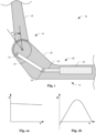
- Fig. 1 shows rotary joint 10 and joint drive 12 of exoskeleton 14.
- Rotary joint 10 connects link 16 and link 18 which can be rotated relative to each other about a common axis of rotation.
- Link 18 is an angled rigid body which may be connected to a shoulder of a user.
- Link 16 is an elongated rigid body which may be used to support a movement of an upper arm of the user.
- Joint drive 12 comprises element 20 which is designed as a push rod and is connected to link 16 by rotary joint 22.
- Joint drive 12 further comprises element 24 which is connected to element 20 by rotary joint 26.
- the axis of rotation of rotary joint 10, the axis of rotation of rotary joint 22, and the axis of rotation of rotary joint 26 are parallel and a center of rotation of rotary joint 22 moves relative to a center of rotation of rotary joint 10 on a circular path when the relative orientation between link 16 and link 18 changes.
- Element 24 is connected to element 18 by linear joint 28. Moreover, element 24 serves as a piston of pneumatic actuator 50 attached to link 18.
- Fig. 1a illustrates the pressure P in pneumatic actuator 50 as a function of the orientation of link 16 and link 18 relative to one another.
- Fig. 1b illustrates the support torque M as a function of the orientation of link 16 and link 18 relative to one another.
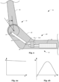
- support torque M may be adjusted (continuously) by changing the distance of the center of rotation of rotary joint 10 and the center of rotation of rotary joint 22.
- the zero crossing of the support torque M may be adjusted to a value ⁇ 1 that is particularly suitable for the respective application scenario, by suitable dimensioning of element 20 and element 24.
- element 24 may be connected to element 20 by transmission 24a (e.g., a gear transmission).
- Fig. 3 shows a possible modification of the arrangements described above with reference to Fig. 1, Fig. 1a, Fig. 1b , Fig. 2, Fig. 2a and Fig. 2b .
- the modification allows for a (stepless) adjustment of the distance between the center of rotation of rotary joint 10 and the center of rotation of rotary joint 22 during operation (e.g., by means of an electric motor, spindle drive, etc.).
- the arrangement shown in Fig. 3 allows for a (stepless) adjustment of the length of element 20 (e.g., by means of an electric motor, spindle drive, etc.).
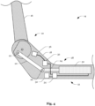
- Fig. 4 shows a possible modification of the arrangements described above with reference to Fig. 1, Fig. 1a, Fig. 1b , Fig. 2, Fig. 2a, Fig. 2b and Fig. 3 .
- the arrangement shown in Fig. 4 additionally comprises compressed air reservoir 30 and controller 32, wherein controller 32 is configured to supply or withdraw compressed air to/from pneumatic actuator 50 via a valve 34 controlled by controller 32, depending on a movement of link 16 relative to link 18, a pose that a user of the exoskeleton 14 assumes or an angular velocity or an angular acceleration.
- the arrangement shown in Fig. 4 comprises a sensor unit 36 with an angle of rotation sensor which is configured to determine a relative angle between link 16 and link 18. Controller 32 may be configured to supply or withdraw compressed air to/from pneumatic actuator 50 depending on the relative angle. Sensor unit 36 may further comprise a gyroscope and/or an accelerometer. The measurement of the gyroscope and/or the acceleration sensor may also be taken into account when supplying or withdrawing compressed air to/from pneumatic actuator 50.
- element 24 may be connected to link 18 by spring 38.
- element 24 may have a magnetic section and exoskeleton 14 may comprise magnet 40 which limits a movement of element 24 relative to link 18 by means of magnetic force 12.
- Fig. 6 shows steps 42a and 42b for adapting joint drive 12, comprising determining that an increase/decrease in support force provided by joint drive 12 is required and adjusting the distance between the center of rotation of rotary joint 10 and the center of rotation of rotary joint 22 or changing the transmission ratio of transmission 24a.
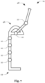
- Fig. 7 shows an exoskeleton 14 with a plurality of rotary joints 10.
- Exoskeleton 14 comprises pelvis connector 44 (for example a pelvic belt), shoulder connector 46 (for example a shoulder belt) and arm connector 48 (for example an arm belt).
- pelvis connector 44 for example a pelvic belt
- shoulder connector 46 for example a shoulder belt
- arm connector 48 for example an arm belt.
- One, two or more rotary joints 10 may be provided with one of the joint drives 12 described above.
Landscapes
- Engineering & Computer Science (AREA)
- Robotics (AREA)
- Mechanical Engineering (AREA)
- Human Computer Interaction (AREA)
- Manipulator (AREA)
- Rehabilitation Tools (AREA)
- Orthopedics, Nursing, And Contraception (AREA)
Description
- The present disclosure relates to an exoskeleton. In particular, the present disclosure relates to an exoskeleton with a joint drive.
- When using an exoskeleton, the level of assistance that is to be provided by the exoskeleton usually depends on the activity and may differ significantly between different poses and movements.
- For example,
US 2018/116828 A1 discloses an exoskeleton according to the preamble of appended claim 1, comprising a joint assembly for use in a modular lower limb. The joint assembly includes a reconfigurable slider-crank mechanism that is configurable to provide a plurality of different ranges of rotational travel, rotational speeds, and torques, for customization according to different anatomical joints. Further exoskeletons according to the preamble of appended claim 1 for use in a modular lower limb are known fromUS 2017/246740 A1 andEP 1260201 A1 . - An exoskeleton according to the invention is defined in appended claim 1 and comprises a first link and a second link connected by a first rotary joint, and a joint drive with a first element and a second element. The first link is an upper arm link and the second link is a shoulder link. The first link is an elongated rigid body and the second link is an angled rigid body. The first element is connected to the first link by a second rotary joint. The second element is connected to the second link by a linear joint. The second element is connected to the first element by a third rotary joint.
- The term "link", as used in the context of the present description and the claims, may refer to a rigid body which forms part of the kinematic chain defining the exoskeleton. Furthermore, the term "element", as used in the context of the present description and the claims, may refer to a rigid component that is configured to transmit a force applied to the component onto another component. Moreover, the term "rotary joint", as used in the context of the present description and the claims, may refer to an arrangement in which two links/elements are connected to one another such that they can be rotated relative to one another about a common axis of rotation.
- Furthermore, the term "joint drive", as used in the context of the present description and the claims, may refer to an arrangement which is configured to control or influence an orientation of the first link relative to the second link. Furthermore, the term "linear joint", as used in the context of the present description and the claims, may refer to an arrangement in which two elements are connected to one another such that they can be linearly moved relative to one another.
- When the orientation of the first link relative to the second link changes, the second axis of rotation may be displaced relative to the second link (along a circular path) causing a change in the length of the lever between the first axis of rotation of the first rotary joint and the second axis of rotation of the second rotary joint.
- A distance between the first rotary joint and the second rotary joint or a distance between the second rotary joint and the third rotary joint may be adjustable. For example, the exoskeleton may comprise an electric motor or a spindle drive which is configured to adjust the distance.
- The first axis of rotation of the first rotary joint, the second axis of rotation of the second rotary joint, and a third axis of rotation of the third rotary joint are parallel.
- The first element may be a push rod.
- The exoskeleton may further comprise an actuator which is attached to the second link. The actuator may be a pneumatic actuator and the second element may be a piston of the pneumatic actuator.
- The second element may be connected to the actuator via a transmission. A transmission ratio of the transmission may be independent of the orientation of the first link relative to the second link.
- The exoskeleton may further comprise a controller which is configured to control a force applied by the actuator to the second element based on a pose of a user of the exoskeleton, a movement of the first link relative to the second link, a speed of the movement, and/or an acceleration of the movement.
- The exoskeleton may further comprise a sensor which is configured to determine an angle between the first link and the second link, wherein the controller is further configured to control the actuator based on the angle.
- The exoskeleton may further comprise a gyroscope or an accelerometer, wherein the controller may be further configured to control the actuator based on the measurements provided by the gyroscope and/or the accelerometer.
- The exoskeleton may further comprise a spring which is attached to the second link, wherein the second element is further connected to the second link by the spring.
- The second element may have a magnetic portion and the exoskeleton comprises a magnet that limits a movement of the second element relative to the second link by magnetic force.
- A method of adapting the exoskeleton to different usage scenarios may comprise determining that an increase in support force provided by the joint drive is required and increasing a distance between the first rotary joint and the second rotary joint during operation.
- The foregoing aspects will be explained in more detail in the following detailed description based on exemplary embodiments, wherein reference is made to the drawings in which:
-
Fig. 1 shows a rotary joint and a joint drive of an exoskeleton; -
Fig. 1a shows a pressure curve versus the angle of rotation; -
Fig. 1b shows a support torque curve versus the joint angle; -
Fig. 2 shows a modification of the joint drive shown inFig. 1 ; -
Fig. 2a shows a pressure curve versus the angle of rotation; -
Fig. 2b shows a support torque curve versus the joint angle; -
Fig. 3 shows a modification of the joint drive shown inFig. 1 ; -
Fig. 4 shows further elements of the joint drive shown inFig. 1 ; -
Fig. 5 shows a modification of the joint drive shown inFig. 4 ; -
Fig. 6 shows a flow chart for adapting the joint drive; and -
Fig. 7 shows an exemplary exoskeleton. - In the drawings, the same or functionally similar elements are indicated by the same reference numerals.
-
Fig. 1 showsrotary joint 10 andjoint drive 12 ofexoskeleton 14.Rotary joint 10 connectslink 16 andlink 18 which can be rotated relative to each other about a common axis of rotation.Link 18 is an angled rigid body which may be connected to a shoulder of a user.Link 16 is an elongated rigid body which may be used to support a movement of an upper arm of the user. -
Joint drive 12 compriseselement 20 which is designed as a push rod and is connected tolink 16 byrotary joint 22.Joint drive 12 further compriseselement 24 which is connected toelement 20 byrotary joint 26. The axis of rotation ofrotary joint 10, the axis of rotation ofrotary joint 22, and the axis of rotation ofrotary joint 26 are parallel and a center of rotation ofrotary joint 22 moves relative to a center of rotation ofrotary joint 10 on a circular path when the relative orientation betweenlink 16 andlink 18 changes. -
Element 24 is connected toelement 18 bylinear joint 28. Moreover,element 24 serves as a piston ofpneumatic actuator 50 attached tolink 18.Fig. 1a illustrates the pressure P inpneumatic actuator 50 as a function of the orientation oflink 16 andlink 18 relative to one another.Fig. 1b illustrates the support torque M as a function of the orientation oflink 16 and link 18 relative to one another. - As illustrated in
Fig. 2, Fig. 2a and Fig. 2c, support torque M may be adjusted (continuously) by changing the distance of the center of rotation of rotary joint 10 and the center of rotation of rotary joint 22. In addition, the zero crossing of the support torque M may be adjusted to a value α1 that is particularly suitable for the respective application scenario, by suitable dimensioning ofelement 20 andelement 24. Furthermore, as shown inFig. 2 ,element 24 may be connected toelement 20 bytransmission 24a (e.g., a gear transmission). -
Fig. 3 shows a possible modification of the arrangements described above with reference toFig. 1, Fig. 1a, Fig. 1b ,Fig. 2, Fig. 2a and Fig. 2b . The modification allows for a (stepless) adjustment of the distance between the center of rotation of rotary joint 10 and the center of rotation of rotary joint 22 during operation (e.g., by means of an electric motor, spindle drive, etc.). Furthermore, the arrangement shown inFig. 3 allows for a (stepless) adjustment of the length of element 20 (e.g., by means of an electric motor, spindle drive, etc.). -
Fig. 4 shows a possible modification of the arrangements described above with reference toFig. 1, Fig. 1a, Fig. 1b ,Fig. 2, Fig. 2a, Fig. 2b andFig. 3 . The arrangement shown inFig. 4 additionally comprises compressed air reservoir 30 andcontroller 32, whereincontroller 32 is configured to supply or withdraw compressed air to/frompneumatic actuator 50 via avalve 34 controlled bycontroller 32, depending on a movement oflink 16 relative to link 18, a pose that a user of theexoskeleton 14 assumes or an angular velocity or an angular acceleration. - To detect the pose, the arrangement shown in
Fig. 4 comprises asensor unit 36 with an angle of rotation sensor which is configured to determine a relative angle betweenlink 16 andlink 18.Controller 32 may be configured to supply or withdraw compressed air to/frompneumatic actuator 50 depending on the relative angle.Sensor unit 36 may further comprise a gyroscope and/or an accelerometer. The measurement of the gyroscope and/or the acceleration sensor may also be taken into account when supplying or withdrawing compressed air to/frompneumatic actuator 50. - As shown in
Fig. 5 ,element 24 may be connected to link 18 byspring 38. Alternatively or additionally,element 24 may have a magnetic section andexoskeleton 14 may comprisemagnet 40 which limits a movement ofelement 24 relative to link 18 by means ofmagnetic force 12. -
Fig. 6 showssteps joint drive 12, comprising determining that an increase/decrease in support force provided byjoint drive 12 is required and adjusting the distance between the center of rotation of rotary joint 10 and the center of rotation of rotary joint 22 or changing the transmission ratio oftransmission 24a. -
Fig. 7 shows anexoskeleton 14 with a plurality of rotary joints 10.Exoskeleton 14 comprises pelvis connector 44 (for example a pelvic belt), shoulder connector 46 (for example a shoulder belt) and arm connector 48 (for example an arm belt). One, two or morerotary joints 10 may be provided with one of the joint drives 12 described above. -
- 10
- rotary joint
- 12
- joint drive
- 14
- exoskeleton
- 16
- link
- 18
- link
- 20
- element
- 22
- rotary joint
- 24
- element
- 24a
- transmission
- 26
- rotary joint
- 28
- linear joint
- 30
- compressed air reservoir
- 32
- controller
- 34
- valve
- 36
- sensor unit
- 38
- spring
- 40
- magnet
- 42a
- step
- 42b
- step
- 44
- pelvis connector
- 46
- shoulder connector
- 48
- arm connector
- 50
- actuator
Claims (15)
- An exoskeleton (14), comprising:a first link (16) and a second link (18), wherein the first link (16) and the second link (18) are rotatable relative to each other about a first axis of rotation, thereby forming a first rotary joint (10) of the exoskeleton (14); anda joint drive (12) with a first element (20) and a second element (24);wherein the first link (16) is an elongated rigid body;wherein the first element (20) is connected to the first link (16) by a second rotary joint (22);wherein the second element (24) is connected to the second link (18) by a linear joint (28); andwherein the second element (24) is connected to the first element (20) by a third rotary joint (26);characterized in thatthe first link (16) is an upper arm link and the second link (18) is a shoulder link; andthe second link (18) is an angled rigid body.
- The exoskeleton (14) of claim 1, wherein the elongated rigid body is configured to support a movement of an upper arm of a user and /or the angled rigid body is configured to be connected to a shoulder of the user.
- The exoskeleton (14) of claim 1 or 2, wherein a second axis of rotation of the second rotary joint (22) is displaced relative to the second link (18) along a circular path when the orientation of the first link (16) relative to the second link (18) changes.
- The exoskeleton (14) of any one of claims 1 to 3, wherein a length of a lever between the first axis of rotation of the first rotary joint (10) and the second axis of rotation of the second rotary joint (22) changes when the orientation of the first link (16) relative to the second link (18) changes.
- The exoskeleton (14) of any one of claims 1 to 4, wherein a first distance between the first rotary joint (10) and the second rotary joint (22) and/or a second distance between the second rotary joint (22) and the third rotary joint (26) are/is adjustable.
- The exoskeleton (14) of claim 5, further comprising:
one of an electric motor and a spindle drive which is configured to adjust the first distance or the second distance. - The exoskeleton (14) of any one of claims 1 to 6, wherein the first axis of rotation of the first rotary joint (10), the second axis of rotation of the second rotary joint (22) and a third axis of rotation of the third rotary joint (26) are parallel.
- The exoskeleton (14) of any one of claims 1 to 7, wherein the first element (20) is a push rod.
- The exoskeleton (14) of any one of claims 1 to 8, further comprising:
an actuator (50) which is attached to the second link (18). - The exoskeleton (14) of claim 9, wherein the actuator (50) is a pneumatic actuator and the second element (24) is a piston of the pneumatic actuator.
- The exoskeleton (14) of claim 9, wherein the second element (24) is connected to the actuator (50) via a transmission (24a), wherein a transmission ratio of the transmission (24a) is preferably independent of the orientation of the first link (16) relative to the second link (18).
- The exoskeleton (14) of any one of claims 9 to 11, further comprising:
a controller (32) which is configured to control a force applied by the actuator (50) to the second element (24) based on at least one of a pose of a user of the exoskeleton (14), a movement of the first link (16) relative to the second link (18), a speed of the movement, and an acceleration of the movement. - The exoskeleton (14) of claim 12, further comprising:a sensor which is configured to determine an angle between the first link (16) and the second link (18), wherein the controller (32) is further configured to control the actuator (50) based on the angle; and/orat least one of a gyroscope and an accelerometer, wherein the controller (32) is further configured to control the actuator (50) based on measurements provided by at least one of the gyroscope and the accelerometer.
- The exoskeleton (14) of any one of claims 1 to 13, further comprising:a spring (38) which is attached to the second link (18), wherein the second element (24) is further connected to the second link (18) by the spring (38); and/orwherein the second element (24) has a magnetic portion and the exoskeleton (14) comprises a magnet (40) that limits a movement of the second element (24) relative to the second link (18) by magnetic force.
- A method of adapting an exoskeleton (14) according to any one of claims 1 to 14 to different usage scenarios, comprising:determining (42a) that an increase in support force provided by the joint drive (12) is required; andincreasing (42b) a distance between the first rotary joint (10) and the second rotary joint (22) during operation.
Applications Claiming Priority (1)
| Application Number | Priority Date | Filing Date | Title |
|---|---|---|---|
| DE102019131005.9A DE102019131005A1 (en) | 2019-11-17 | 2019-11-17 | EXOSKELETO JOINT DRIVE WITH NON-LINEAR TRANSMISSION |
Publications (2)
| Publication Number | Publication Date |
|---|---|
| EP3822044A1 EP3822044A1 (en) | 2021-05-19 |
| EP3822044B1 true EP3822044B1 (en) | 2024-01-10 |
Family
ID=73475857
Family Applications (1)
| Application Number | Title | Priority Date | Filing Date |
|---|---|---|---|
| EP20207977.8A Active EP3822044B1 (en) | 2019-11-17 | 2020-11-17 | Exoskeleton joint drive with non-linear transmission |
Country Status (3)
| Country | Link |
|---|---|
| US (1) | US20210146527A1 (en) |
| EP (1) | EP3822044B1 (en) |
| DE (1) | DE102019131005A1 (en) |
Families Citing this family (2)
| Publication number | Priority date | Publication date | Assignee | Title |
|---|---|---|---|---|
| WO2023091099A1 (en) * | 2021-11-18 | 2023-05-25 | Ocali̇s Mühendi̇sli̇k Anoni̇m Şi̇rketi̇ | Wearable arm support system |
| EP4601835A1 (en) * | 2022-10-10 | 2025-08-20 | Iuvo S.r.L. | Torque generator device |
Family Cites Families (12)
| Publication number | Priority date | Publication date | Assignee | Title |
|---|---|---|---|---|
| US5252102A (en) * | 1989-01-24 | 1993-10-12 | Electrobionics Corporation | Electronic range of motion apparatus, for orthosis, prosthesis, and CPM machine |
| US7153242B2 (en) * | 2001-05-24 | 2006-12-26 | Amit Goffer | Gait-locomotor apparatus |
| US6969365B2 (en) * | 2002-04-16 | 2005-11-29 | Scorvo Sean K | Adjustable orthotic brace |
| US7862524B2 (en) * | 2006-03-23 | 2011-01-04 | Carignan Craig R | Portable arm exoskeleton for shoulder rehabilitation |
| US9017418B2 (en) * | 2009-05-05 | 2015-04-28 | össur hf | Control systems and methods for prosthetic or orthotic devices |
| US8939924B1 (en) * | 2009-05-18 | 2015-01-27 | The Lonnie and Shannon Paulos Trust | Magnet assisted orthotic brace |
| US10518404B2 (en) * | 2015-07-17 | 2019-12-31 | Lockheed Martin Corporation | Variable force exoskeleton hip joint |
| CN105798893B (en) * | 2016-06-03 | 2017-09-12 | 河北工业大学 | One kind auxiliary heavy burden human body lower limbs ectoskeleton |
| WO2018093448A2 (en) * | 2016-09-09 | 2018-05-24 | Qatar Foundation For Education, Science And Community Development | Robotic upper limb rehabilitation device |
| US11191653B2 (en) * | 2016-11-03 | 2021-12-07 | University Of New Brunswick | Powered lower limb devices and methods of control thereof |
| DE102017103265A1 (en) * | 2017-02-17 | 2018-08-23 | André Herzog | Stationary whole body exoskeleton as a haptic interface with pressure-controllable contact surfaces and a novel hand exoskeleton |
| CA3098479C (en) * | 2018-05-14 | 2021-06-08 | Human In Motion Robotics Inc. | Self-supported device for guiding motions of a target joint |
-
2019
- 2019-11-17 DE DE102019131005.9A patent/DE102019131005A1/en not_active Withdrawn
-
2020
- 2020-11-16 US US17/099,200 patent/US20210146527A1/en not_active Abandoned
- 2020-11-17 EP EP20207977.8A patent/EP3822044B1/en active Active
Also Published As
| Publication number | Publication date |
|---|---|
| DE102019131005A1 (en) | 2021-05-20 |
| US20210146527A1 (en) | 2021-05-20 |
| EP3822044A1 (en) | 2021-05-19 |
Similar Documents
| Publication | Publication Date | Title |
|---|---|---|
| US10953553B2 (en) | Gripping hand | |
| CN108698223B (en) | Robot joint and robot having at least one such robot joint | |
| US11337881B2 (en) | Exoskeleton with admittance control | |
| EP3293600B1 (en) | Three-axis motion joystick | |
| CN106078724B (en) | Mechanical arm and surgical robot thereof | |
| US9850108B2 (en) | Movement system configured for moving a payload | |
| EP3442756B1 (en) | Variable stiffness series elastic actuator | |
| US10875628B2 (en) | Inherently balanced control stick | |
| EP1885525B1 (en) | Articulated joint | |
| EP3822044A1 (en) | Exoskeleton joint drive with non-linear transmission | |
| EP3172153A1 (en) | Modular base link for a counterbalancing arm | |
| CA2562594C (en) | Attitude detection method and apparatus for initial motion control | |
| WO2019012431A1 (en) | Electric machine with integrated gearbox | |
| US9209740B2 (en) | Actuating apparatus | |
| EP0060483A1 (en) | Manipulator robot | |
| KR20030085779A (en) | Parallel Manipulator with Resizable Platform | |
| KR20030044193A (en) | Omni-directional vehicle with continuous variable transmission | |
| JP2000127776A (en) | Omnidirectional vehicle and drive mechanism control method thereof | |
| EP3253997B1 (en) | Phased joint cam | |
| Yamamoto et al. | Load balancer with automatic lifting force compensation | |
| KR20130097480A (en) | Steering device for vehicle capable of cycle steering and vehicle having the same | |
| EP4644212A1 (en) | Steer-by-wire steering assembly with a torque generator | |
| JP7533296B2 (en) | Damper device, output torque variable system, output torque variable method, and output torque variable program | |
| KR20160063826A (en) | Link-arm robot comprising vibration-reduction apparatus for improving accuracy | |
| EP4439530A1 (en) | Oscillation device and method for controlling oscillation device |
Legal Events
| Date | Code | Title | Description |
|---|---|---|---|
| PUAI | Public reference made under article 153(3) epc to a published international application that has entered the european phase |
Free format text: ORIGINAL CODE: 0009012 |
|
| STAA | Information on the status of an ep patent application or granted ep patent |
Free format text: STATUS: THE APPLICATION HAS BEEN PUBLISHED |
|
| AK | Designated contracting states |
Kind code of ref document: A1 Designated state(s): AL AT BE BG CH CY CZ DE DK EE ES FI FR GB GR HR HU IE IS IT LI LT LU LV MC MK MT NL NO PL PT RO RS SE SI SK SM TR |
|
| STAA | Information on the status of an ep patent application or granted ep patent |
Free format text: STATUS: REQUEST FOR EXAMINATION WAS MADE |
|
| 17P | Request for examination filed |
Effective date: 20211119 |
|
| RBV | Designated contracting states (corrected) |
Designated state(s): AL AT BE BG CH CY CZ DE DK EE ES FI FR GB GR HR HU IE IS IT LI LT LU LV MC MK MT NL NO PL PT RO RS SE SI SK SM TR |
|
| P01 | Opt-out of the competence of the unified patent court (upc) registered |
Effective date: 20230524 |
|
| GRAP | Despatch of communication of intention to grant a patent |
Free format text: ORIGINAL CODE: EPIDOSNIGR1 |
|
| STAA | Information on the status of an ep patent application or granted ep patent |
Free format text: STATUS: GRANT OF PATENT IS INTENDED |
|
| INTG | Intention to grant announced |
Effective date: 20230630 |
|
| GRAS | Grant fee paid |
Free format text: ORIGINAL CODE: EPIDOSNIGR3 |
|
| GRAA | (expected) grant |
Free format text: ORIGINAL CODE: 0009210 |
|
| STAA | Information on the status of an ep patent application or granted ep patent |
Free format text: STATUS: THE PATENT HAS BEEN GRANTED |
|
| AK | Designated contracting states |
Kind code of ref document: B1 Designated state(s): AL AT BE BG CH CY CZ DE DK EE ES FI FR GB GR HR HU IE IS IT LI LT LU LV MC MK MT NL NO PL PT RO RS SE SI SK SM TR |
|
| REG | Reference to a national code |
Ref country code: GB Ref legal event code: FG4D |
|
| REG | Reference to a national code |
Ref country code: CH Ref legal event code: EP |
|
| REG | Reference to a national code |
Ref country code: DE Ref legal event code: R096 Ref document number: 602020024145 Country of ref document: DE |
|
| REG | Reference to a national code |
Ref country code: IE Ref legal event code: FG4D |
|
| REG | Reference to a national code |
Ref country code: LT Ref legal event code: MG9D |
|
| REG | Reference to a national code |
Ref country code: NL Ref legal event code: MP Effective date: 20240110 |
|
| REG | Reference to a national code |
Ref country code: AT Ref legal event code: MK05 Ref document number: 1648555 Country of ref document: AT Kind code of ref document: T Effective date: 20240110 |
|
| PG25 | Lapsed in a contracting state [announced via postgrant information from national office to epo] |
Ref country code: NL Free format text: LAPSE BECAUSE OF FAILURE TO SUBMIT A TRANSLATION OF THE DESCRIPTION OR TO PAY THE FEE WITHIN THE PRESCRIBED TIME-LIMIT Effective date: 20240110 |
|
| PG25 | Lapsed in a contracting state [announced via postgrant information from national office to epo] |
Ref country code: NL Free format text: LAPSE BECAUSE OF FAILURE TO SUBMIT A TRANSLATION OF THE DESCRIPTION OR TO PAY THE FEE WITHIN THE PRESCRIBED TIME-LIMIT Effective date: 20240110 |
|
| PG25 | Lapsed in a contracting state [announced via postgrant information from national office to epo] |
Ref country code: IS Free format text: LAPSE BECAUSE OF FAILURE TO SUBMIT A TRANSLATION OF THE DESCRIPTION OR TO PAY THE FEE WITHIN THE PRESCRIBED TIME-LIMIT Effective date: 20240510 |
|
| PG25 | Lapsed in a contracting state [announced via postgrant information from national office to epo] |
Ref country code: LT Free format text: LAPSE BECAUSE OF FAILURE TO SUBMIT A TRANSLATION OF THE DESCRIPTION OR TO PAY THE FEE WITHIN THE PRESCRIBED TIME-LIMIT Effective date: 20240110 |
|
| PG25 | Lapsed in a contracting state [announced via postgrant information from national office to epo] |
Ref country code: GR Free format text: LAPSE BECAUSE OF FAILURE TO SUBMIT A TRANSLATION OF THE DESCRIPTION OR TO PAY THE FEE WITHIN THE PRESCRIBED TIME-LIMIT Effective date: 20240411 |
|
| PG25 | Lapsed in a contracting state [announced via postgrant information from national office to epo] |
Ref country code: HR Free format text: LAPSE BECAUSE OF FAILURE TO SUBMIT A TRANSLATION OF THE DESCRIPTION OR TO PAY THE FEE WITHIN THE PRESCRIBED TIME-LIMIT Effective date: 20240110 Ref country code: RS Free format text: LAPSE BECAUSE OF FAILURE TO SUBMIT A TRANSLATION OF THE DESCRIPTION OR TO PAY THE FEE WITHIN THE PRESCRIBED TIME-LIMIT Effective date: 20240410 |
|
| PG25 | Lapsed in a contracting state [announced via postgrant information from national office to epo] |
Ref country code: ES Free format text: LAPSE BECAUSE OF FAILURE TO SUBMIT A TRANSLATION OF THE DESCRIPTION OR TO PAY THE FEE WITHIN THE PRESCRIBED TIME-LIMIT Effective date: 20240110 |
|
| PG25 | Lapsed in a contracting state [announced via postgrant information from national office to epo] |
Ref country code: AT Free format text: LAPSE BECAUSE OF FAILURE TO SUBMIT A TRANSLATION OF THE DESCRIPTION OR TO PAY THE FEE WITHIN THE PRESCRIBED TIME-LIMIT Effective date: 20240110 |
|
| PG25 | Lapsed in a contracting state [announced via postgrant information from national office to epo] |
Ref country code: RS Free format text: LAPSE BECAUSE OF FAILURE TO SUBMIT A TRANSLATION OF THE DESCRIPTION OR TO PAY THE FEE WITHIN THE PRESCRIBED TIME-LIMIT Effective date: 20240410 Ref country code: NO Free format text: LAPSE BECAUSE OF FAILURE TO SUBMIT A TRANSLATION OF THE DESCRIPTION OR TO PAY THE FEE WITHIN THE PRESCRIBED TIME-LIMIT Effective date: 20240410 Ref country code: LT Free format text: LAPSE BECAUSE OF FAILURE TO SUBMIT A TRANSLATION OF THE DESCRIPTION OR TO PAY THE FEE WITHIN THE PRESCRIBED TIME-LIMIT Effective date: 20240110 Ref country code: IS Free format text: LAPSE BECAUSE OF FAILURE TO SUBMIT A TRANSLATION OF THE DESCRIPTION OR TO PAY THE FEE WITHIN THE PRESCRIBED TIME-LIMIT Effective date: 20240510 Ref country code: HR Free format text: LAPSE BECAUSE OF FAILURE TO SUBMIT A TRANSLATION OF THE DESCRIPTION OR TO PAY THE FEE WITHIN THE PRESCRIBED TIME-LIMIT Effective date: 20240110 Ref country code: GR Free format text: LAPSE BECAUSE OF FAILURE TO SUBMIT A TRANSLATION OF THE DESCRIPTION OR TO PAY THE FEE WITHIN THE PRESCRIBED TIME-LIMIT Effective date: 20240411 Ref country code: ES Free format text: LAPSE BECAUSE OF FAILURE TO SUBMIT A TRANSLATION OF THE DESCRIPTION OR TO PAY THE FEE WITHIN THE PRESCRIBED TIME-LIMIT Effective date: 20240110 Ref country code: BG Free format text: LAPSE BECAUSE OF FAILURE TO SUBMIT A TRANSLATION OF THE DESCRIPTION OR TO PAY THE FEE WITHIN THE PRESCRIBED TIME-LIMIT Effective date: 20240110 Ref country code: AT Free format text: LAPSE BECAUSE OF FAILURE TO SUBMIT A TRANSLATION OF THE DESCRIPTION OR TO PAY THE FEE WITHIN THE PRESCRIBED TIME-LIMIT Effective date: 20240110 |
|
| PG25 | Lapsed in a contracting state [announced via postgrant information from national office to epo] |
Ref country code: PT Free format text: LAPSE BECAUSE OF FAILURE TO SUBMIT A TRANSLATION OF THE DESCRIPTION OR TO PAY THE FEE WITHIN THE PRESCRIBED TIME-LIMIT Effective date: 20240510 Ref country code: PL Free format text: LAPSE BECAUSE OF FAILURE TO SUBMIT A TRANSLATION OF THE DESCRIPTION OR TO PAY THE FEE WITHIN THE PRESCRIBED TIME-LIMIT Effective date: 20240110 |
|
| PG25 | Lapsed in a contracting state [announced via postgrant information from national office to epo] |
Ref country code: SE Free format text: LAPSE BECAUSE OF FAILURE TO SUBMIT A TRANSLATION OF THE DESCRIPTION OR TO PAY THE FEE WITHIN THE PRESCRIBED TIME-LIMIT Effective date: 20240110 Ref country code: PT Free format text: LAPSE BECAUSE OF FAILURE TO SUBMIT A TRANSLATION OF THE DESCRIPTION OR TO PAY THE FEE WITHIN THE PRESCRIBED TIME-LIMIT Effective date: 20240510 Ref country code: PL Free format text: LAPSE BECAUSE OF FAILURE TO SUBMIT A TRANSLATION OF THE DESCRIPTION OR TO PAY THE FEE WITHIN THE PRESCRIBED TIME-LIMIT Effective date: 20240110 Ref country code: LV Free format text: LAPSE BECAUSE OF FAILURE TO SUBMIT A TRANSLATION OF THE DESCRIPTION OR TO PAY THE FEE WITHIN THE PRESCRIBED TIME-LIMIT Effective date: 20240110 |
|
| PG25 | Lapsed in a contracting state [announced via postgrant information from national office to epo] |
Ref country code: DK Free format text: LAPSE BECAUSE OF FAILURE TO SUBMIT A TRANSLATION OF THE DESCRIPTION OR TO PAY THE FEE WITHIN THE PRESCRIBED TIME-LIMIT Effective date: 20240110 |
|
| REG | Reference to a national code |
Ref country code: DE Ref legal event code: R097 Ref document number: 602020024145 Country of ref document: DE |
|
| PG25 | Lapsed in a contracting state [announced via postgrant information from national office to epo] |
Ref country code: SM Free format text: LAPSE BECAUSE OF FAILURE TO SUBMIT A TRANSLATION OF THE DESCRIPTION OR TO PAY THE FEE WITHIN THE PRESCRIBED TIME-LIMIT Effective date: 20240110 |
|
| PG25 | Lapsed in a contracting state [announced via postgrant information from national office to epo] |
Ref country code: CZ Free format text: LAPSE BECAUSE OF FAILURE TO SUBMIT A TRANSLATION OF THE DESCRIPTION OR TO PAY THE FEE WITHIN THE PRESCRIBED TIME-LIMIT Effective date: 20240110 Ref country code: EE Free format text: LAPSE BECAUSE OF FAILURE TO SUBMIT A TRANSLATION OF THE DESCRIPTION OR TO PAY THE FEE WITHIN THE PRESCRIBED TIME-LIMIT Effective date: 20240110 |
|
| PG25 | Lapsed in a contracting state [announced via postgrant information from national office to epo] |
Ref country code: SK Free format text: LAPSE BECAUSE OF FAILURE TO SUBMIT A TRANSLATION OF THE DESCRIPTION OR TO PAY THE FEE WITHIN THE PRESCRIBED TIME-LIMIT Effective date: 20240110 |
|
| PG25 | Lapsed in a contracting state [announced via postgrant information from national office to epo] |
Ref country code: SM Free format text: LAPSE BECAUSE OF FAILURE TO SUBMIT A TRANSLATION OF THE DESCRIPTION OR TO PAY THE FEE WITHIN THE PRESCRIBED TIME-LIMIT Effective date: 20240110 Ref country code: SK Free format text: LAPSE BECAUSE OF FAILURE TO SUBMIT A TRANSLATION OF THE DESCRIPTION OR TO PAY THE FEE WITHIN THE PRESCRIBED TIME-LIMIT Effective date: 20240110 Ref country code: RO Free format text: LAPSE BECAUSE OF FAILURE TO SUBMIT A TRANSLATION OF THE DESCRIPTION OR TO PAY THE FEE WITHIN THE PRESCRIBED TIME-LIMIT Effective date: 20240110 Ref country code: EE Free format text: LAPSE BECAUSE OF FAILURE TO SUBMIT A TRANSLATION OF THE DESCRIPTION OR TO PAY THE FEE WITHIN THE PRESCRIBED TIME-LIMIT Effective date: 20240110 Ref country code: DK Free format text: LAPSE BECAUSE OF FAILURE TO SUBMIT A TRANSLATION OF THE DESCRIPTION OR TO PAY THE FEE WITHIN THE PRESCRIBED TIME-LIMIT Effective date: 20240110 Ref country code: CZ Free format text: LAPSE BECAUSE OF FAILURE TO SUBMIT A TRANSLATION OF THE DESCRIPTION OR TO PAY THE FEE WITHIN THE PRESCRIBED TIME-LIMIT Effective date: 20240110 |
|
| PLBE | No opposition filed within time limit |
Free format text: ORIGINAL CODE: 0009261 |
|
| STAA | Information on the status of an ep patent application or granted ep patent |
Free format text: STATUS: NO OPPOSITION FILED WITHIN TIME LIMIT |
|
| PG25 | Lapsed in a contracting state [announced via postgrant information from national office to epo] |
Ref country code: IT Free format text: LAPSE BECAUSE OF FAILURE TO SUBMIT A TRANSLATION OF THE DESCRIPTION OR TO PAY THE FEE WITHIN THE PRESCRIBED TIME-LIMIT Effective date: 20240110 |
|
| 26N | No opposition filed |
Effective date: 20241011 |
|
| PG25 | Lapsed in a contracting state [announced via postgrant information from national office to epo] |
Ref country code: IT Free format text: LAPSE BECAUSE OF FAILURE TO SUBMIT A TRANSLATION OF THE DESCRIPTION OR TO PAY THE FEE WITHIN THE PRESCRIBED TIME-LIMIT Effective date: 20240110 |
|
| PG25 | Lapsed in a contracting state [announced via postgrant information from national office to epo] |
Ref country code: SI Free format text: LAPSE BECAUSE OF FAILURE TO SUBMIT A TRANSLATION OF THE DESCRIPTION OR TO PAY THE FEE WITHIN THE PRESCRIBED TIME-LIMIT Effective date: 20240110 |
|
| REG | Reference to a national code |
Ref country code: CH Ref legal event code: PL |
|
| PG25 | Lapsed in a contracting state [announced via postgrant information from national office to epo] |
Ref country code: MC Free format text: LAPSE BECAUSE OF FAILURE TO SUBMIT A TRANSLATION OF THE DESCRIPTION OR TO PAY THE FEE WITHIN THE PRESCRIBED TIME-LIMIT Effective date: 20240110 |
|
| PG25 | Lapsed in a contracting state [announced via postgrant information from national office to epo] |
Ref country code: LU Free format text: LAPSE BECAUSE OF NON-PAYMENT OF DUE FEES Effective date: 20241117 |
|
| REG | Reference to a national code |
Ref country code: CH Ref legal event code: PL |
|
| GBPC | Gb: european patent ceased through non-payment of renewal fee |
Effective date: 20241117 |
|
| PG25 | Lapsed in a contracting state [announced via postgrant information from national office to epo] |
Ref country code: CH Free format text: LAPSE BECAUSE OF NON-PAYMENT OF DUE FEES Effective date: 20241130 |
|
| REG | Reference to a national code |
Ref country code: BE Ref legal event code: MM Effective date: 20241130 |
|
| PG25 | Lapsed in a contracting state [announced via postgrant information from national office to epo] |
Ref country code: FI Free format text: LAPSE BECAUSE OF FAILURE TO SUBMIT A TRANSLATION OF THE DESCRIPTION OR TO PAY THE FEE WITHIN THE PRESCRIBED TIME-LIMIT Effective date: 20240110 |
|
| PG25 | Lapsed in a contracting state [announced via postgrant information from national office to epo] |
Ref country code: GB Free format text: LAPSE BECAUSE OF NON-PAYMENT OF DUE FEES Effective date: 20241117 Ref country code: BE Free format text: LAPSE BECAUSE OF NON-PAYMENT OF DUE FEES Effective date: 20241130 |
|
| PG25 | Lapsed in a contracting state [announced via postgrant information from national office to epo] |
Ref country code: IE Free format text: LAPSE BECAUSE OF NON-PAYMENT OF DUE FEES Effective date: 20241117 |
|
| PGFP | Annual fee paid to national office [announced via postgrant information from national office to epo] |
Ref country code: DE Payment date: 20251130 Year of fee payment: 6 |
|
| PGFP | Annual fee paid to national office [announced via postgrant information from national office to epo] |
Ref country code: FR Payment date: 20251008 Year of fee payment: 6 |
|
| PG25 | Lapsed in a contracting state [announced via postgrant information from national office to epo] |
Ref country code: HU Free format text: LAPSE BECAUSE OF FAILURE TO SUBMIT A TRANSLATION OF THE DESCRIPTION OR TO PAY THE FEE WITHIN THE PRESCRIBED TIME-LIMIT; INVALID AB INITIO Effective date: 20201117 |
|
| PG25 | Lapsed in a contracting state [announced via postgrant information from national office to epo] |
Ref country code: CY Free format text: LAPSE BECAUSE OF FAILURE TO SUBMIT A TRANSLATION OF THE DESCRIPTION OR TO PAY THE FEE WITHIN THE PRESCRIBED TIME-LIMIT; INVALID AB INITIO Effective date: 20201117 |
|
| PG25 | Lapsed in a contracting state [announced via postgrant information from national office to epo] |
Ref country code: TR Free format text: LAPSE BECAUSE OF FAILURE TO SUBMIT A TRANSLATION OF THE DESCRIPTION OR TO PAY THE FEE WITHIN THE PRESCRIBED TIME-LIMIT Effective date: 20240110 |