EP3822039A1 - Improved self-balancing tool guide - Google Patents
Improved self-balancing tool guide Download PDFInfo
- Publication number
- EP3822039A1 EP3822039A1 EP19209470.4A EP19209470A EP3822039A1 EP 3822039 A1 EP3822039 A1 EP 3822039A1 EP 19209470 A EP19209470 A EP 19209470A EP 3822039 A1 EP3822039 A1 EP 3822039A1
- Authority
- EP
- European Patent Office
- Prior art keywords
- tool guide
- self
- additional
- lifting mechanism
- wheels
- Prior art date
- Legal status (The legal status is an assumption and is not a legal conclusion. Google has not performed a legal analysis and makes no representation as to the accuracy of the status listed.)
- Withdrawn
Links
Images



Classifications
-
- B—PERFORMING OPERATIONS; TRANSPORTING
- B25—HAND TOOLS; PORTABLE POWER-DRIVEN TOOLS; MANIPULATORS
- B25H—WORKSHOP EQUIPMENT, e.g. FOR MARKING-OUT WORK; STORAGE MEANS FOR WORKSHOPS
- B25H1/00—Work benches; Portable stands or supports for positioning portable tools or work to be operated on thereby
- B25H1/0021—Stands, supports or guiding devices for positioning portable tools or for securing them to the work
- B25H1/0028—Tool balancers
-
- B—PERFORMING OPERATIONS; TRANSPORTING
- B25—HAND TOOLS; PORTABLE POWER-DRIVEN TOOLS; MANIPULATORS
- B25H—WORKSHOP EQUIPMENT, e.g. FOR MARKING-OUT WORK; STORAGE MEANS FOR WORKSHOPS
- B25H1/00—Work benches; Portable stands or supports for positioning portable tools or work to be operated on thereby
- B25H1/0021—Stands, supports or guiding devices for positioning portable tools or for securing them to the work
- B25H1/0035—Extensible supports, e.g. telescopic
Definitions
- the invention relates to an improved self-balancing tool guide for the tool.
- Suspended ceilings are a common design element in large buildings, especially in industrial and office buildings.
- Technical installations such as electrical installations, ventilation systems, lighting and sound insulation, can be laid between the ceiling of the shell construction and the suspended ceiling and are accessible for subsequent inspection and maintenance.
- Load-bearing substructures of the installations and the suspended ceiling are fixed with dowels, screws or similar elements anchored in the ceiling of the shell construction.
- To build the suspended ceiling holes are drilled in the ceiling of the shell, in which the dowels can be used or the screws can be screwed. A lateral position of the holes is predetermined by the supporting substructure.
- Drilling the holes is time consuming.
- the user can reach the high-hanging ceiling of the shell construction only with a ladder or scaffolding.
- the ladder must be placed below the predetermined position, the user climbs up the ladder, drills the hole, descends the ladder, and shifts the ladder to the next position.
- DE 33 28 582 A1 describes a mobile ceiling drilling and mounting device for the installation of knock-in anchors in a ceiling.
- the ceiling drill is based on an impact drill, which is mounted on a telescopic column.
- the telescopic column is suspended oscillating on a trolley.
- the user can drive the ceiling drill below a desired location, apply the impact drill to the ceiling by means of the column and drill a hole in the ceiling.
- the impact drill can be controlled via a control cabinet.
- the device For transporting over stairwells, the device must be divided into four parts - carriage, telescopic column, impact drill and control cabinet.
- WO2019101482 A1 describes a self-aligning tool guide.
- the tool guide has a mounting, a lifting mechanism and a chassis.
- the self-aligning tool guide allows for a very compact and lightweight design by reducing the number of assemblies.
- the axis of the tool is aligned by the drive control and wheels. In a deflection of the tool from the predetermined direction, the wheels actively exert a counter-torque, which aligns the tool correctly again. This is especially necessary when applying the tool to the ceiling.
- the dynamic stabilization enables a stable footing of the tool guide already on one wheel or on two wheels.
- such a tool guide system usually is quite high, almost reaching to the ceiling, it is unstable either in driving mode or standing mode.
- the position of the tool guide system sometimes cannot be very accurately as expected. Also, if the tool guide system moves too fast, there would be highly possible to fall down due to its high gravity center. Therefore, it is necessary to improve the stability, increase the accuracy of the positioning and moving speed.
- the primary object of the present invention is to provide an improved self-aligning tool guide. for anchorage in a bore hole that can be used also for heavy loads, that can perfectly balance three functions of the collapsible function, the anti-spinning and setting functions.
- An embodiment of the invention relates to an improved self-aligning tool guide.
- the tool guide has a mounting, a lifting mechanism and a self-balancing chassis.
- the mounting is for fixing a hand-held machine tool.
- the mounting is mounted on the lifting mechanism.
- the lifting mechanism has a propulsion unit for vertical lifting of the mounting.
- the self-balancing chassis has two wheels on a wheel axle, a drive coupled with the wheels and a steering system.
- a center of gravity sensor is mounted to detect a lateral deflection of the center of gravity of the lifting mechanism relative to the wheel axle.
- the steering is set up to control the drive, to output a torque counteracting the deflection (x).
- An additional self-balancing member is mounted on the upper portion of the tool guide to deliver an additional torque for balancing the tool guide.
- the additional self-balancing member calculates the additional torque compensatory counteracting the deflection complementarily.
- the additional self-balancing member creates the additional torque applying to the wheels.
- the axis of the tool is aligned by the drive control and wheels.
- the wheels were controlled by the drive, and actively exert a counter-torque, which aligns the tool correctly again.
- the additional self-balancing member work together with the drive, in a deflection of the tool from the predetermined direction, especially an accuracy of the position or moving is needed, the additional self-balancing member actively detect the deflection, and calculate a target additional torque for counteracting the deflection complementarily, then exert the additional counter-torque on upper portion of the tool guide, which aligns the tool correctly again with no movement of the wheels.
- the dynamic stabilization enables a stable footing of the tool guide already on wheels.
- the additional self-balancing member holds the upper part of the tool guide in upright position.
- the tool guide usually touches the ground only with the two wheels. An upright standing position is ensured by the additional balancing member.
- the additional self-balancing member creates an additional force (leading to a counteracting torque), apply this additional torque on top of the tool guide, which can hold the tool guide in upright position, to increase the stability.
- the additional torque created by the additional self-balancing member accelerated the tool guide's movement in a desired direction. Since the additional torque on the top enables the device to lean fast in a desired direction, which is needed to move forward. It is useful for being able to move fast. Therefore, the tool guide improves the accuracy of speed and position when it works.
- the additional self-balancing member is a propeller.
- the additional self-balancing member can be a moving mass or compressed air. Anything which can creates force/torque on the upper portion of the tool guide can be used.
- the self-aligning tool guide allows for a very compact and lightweight design.
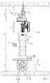
- Fig. 1 to Fig. 3 show an exemplary improved self-aligning tool guide 1 for installation work in a shell construction.
- An assembly of a ventilation pipe requires, for example, several holes 2 in a ceiling 3 of the shell construction.
- the holes 2 should lie at predetermined positions 4, e.g. in alignment.
- the holes 2 should be parallel to each other, for example oriented vertically.
- Position 4 is entered in a plan, for example. A foreman can mark the position 4 by color markings on the ceiling 3 of the shell construction.
- Other installation work on the ceiling 3 may include setting nails, driving in screws, grinding, etc.
- Fig. 1 to Fig. 3 schematically show an embodiment of the improved self-aligning tool guide 1
- the tool guide 1 has a mounting 5 for a hand-held machine tool 6, a motorized lifting mechanism 7, a motorized chassis 8, a controller 9, a console 10 and an additional self-balancing member 100.
- the user can set up the tool guide 1 with a suitable hand-held machine tool 6 and a suitable tool 11 according to the application.
- a suitable hand-held machine tool 6 for drilling holes 2 in a shell construction this would be, for example, an impact drill with a hammer mechanism 12 and a drill with a sintered carbide tip.
- the hand-held machine tool 6 can be used in the mounting 5 on the lifting mechanism 7.
- a lock 13 secures the hand-held machine tool 6 in the mounting 5.
- the lock 13 is preferably releasable without tools.
- the power tool with the mounting may be 5 be permanently connected, for example, it may be screwed.
- the impact drill is just one example of a hand-held machine tool 6.
- Other examples are an electric screwdriver, a nail setter, an angle grinder, a glue gun, a paint spray gun, etc.
- One type of hand-held machine tool 6 drives a replaceable tool 11 e.g. the drill, a chisel, a screwdriver bit, a cutting disc, etc. for its function.
- Another type of hand-held machine tool 6 directly processes a consumable, e.g. nails, screws, paint, glue.
- the hand-held machine tools 6 are characterized by an own drive, with which the tool 11 is driven or the consumable is driven or applied. The user does not have to apply manual force for the use of the hand-held machine tool 6.
- the hand-held machine tools are referred to as power tools.
- the power source 14 may be electric or fuel-driven. Examples are an electric motor, an electric pump, a gas-fed combustion chamber, a powder-driven piston, etc.
- the power source 14 is coupled to a (trigger) button 15. When the trigger button 15 is pressed, the power source 14 is activated.
- the trigger button 15 is preferably remotely triggered or locked.
- the hand-held machine tool 6 may be a commercially available hand-held machine tool 6.
- the hand-held machine tool 6 has a handle 16 and typically a housing portion 17 for fastening an additional handle.
- the hand-held machine tool 6 may be formed without a handle.
- the mounting 5 may also be designed for non-handheld machine tools.
- the hand-held machine tool 6 has a working axis 18 defined by its structure A tip of the tool 11 or a tip of the consumable lies on the working axis 18 The tip is moved along the working axis 18. The tip first touches the surface to be machined, e.g. the ceiling 3.
- An additional self-balancing member 100 is mounted on the upper portion of the tool guide.
- the additional member 100 could be mounted between the mounting 5 and the lifting mechanism 7.
- the additional self-balancing member is connected to the lifting mechanism and can move along a fixed lifting axis 25 when the lifting mechanism 7 raises or lowers the mounting 5.
- the additional balancing member is rigidly connected to the top of the lifting mechanism 7.
- the additional self-balancing member 100 can create an additional force (leading to a torque) on upper part of the tool guide 1, exert the torque on the wheels.
- This additional self-balancing member 100 can hold the tool guide 1 in the upright position, which is needed to increase the stability. It is also useful for being able to move fast.
- the additional self-balancing member 100 is a propeller 101.
- it also can be a moving mass or compressed air.
- Another example of the additional self-balancing member is a reaction wheel.
- the propeller 101 is rigidly connected to the tool guide 1, between the mounting 5 and the lifting mechanism 7.
- the propeller 101 is electronically connected to the steering system 20. As it is well known, the propeller can create a force when it is activated.
- a status diagram of the tool guide 1 is shown in Fig. 4 .
- the user activates the tool guide 1 by means of the console 10.
- the chassis 8 is in a (driving) mode S1 in which the user can move the tool guide 1 through the room on the floor 19.
- the controller 9 activates a steering system 20 of the tool guide 1.
- the user can set the direction of travel and speed via the console 10.
- the user steers the tool guide 1 to one of the marked positions 4.
- the chassis 8 has a drive 21 which moves the chassis 8 over the ground 19 on its own power.
- Direction and speed of movement of the chassis 8 are controlled by the steering system 20 of the tool guide 1.
- the positioning accuracy and speed that can be reached by controlling the steering system 20 is limited.
- the propeller 101 is also activated by the controller and creates an additional force leading to an additional torque, then exert the correct target torque to the wheels 27. This is useful for being able to move fast, since the torque on top enables the device to lean fast in a desired direction, which is needed to move forward.
- the user puts the chassis 8 in a (standing) mode S2.
- the controller 9 locks the steering system 20 for the user or deactivates the steering system 20.
- the steering system 20 ignores specifications for speed and direction of travel via the console 10.
- the tool guide 1 remains in the currently occupied position 4.
- the steering system 20 can detect the current position 4. If the chassis 8 leaves the current position 4 or is shifted from this, the steering system 20 automatically generates control signals to drive the chassis 8 back to the detected position 4.
- the propeller 101 also help the chassis 8 hole the whole device of tool guide 1 in upright position.
- the propeller 101 is activated, and then calculate a target torque needed for complementarily counteracting the deflection or deviation, exert the torque on the wheels 27, thereby holding the tool guide in the exactly correct position in upright direction allowing no movements of the wheels 27.
- the user can activate a (lifting) mode S3 via the console 10 in order to lift the hand-held machine tool 6 with the lifting mechanism 7.
- the controller 9 forces the standing mode S2 for the chassis 8 before the lift mode can be activated.
- the controller 9 can delay the activation of the lift mode until the chassis 8 is stationary.
- a control station 22 is enabled or activated for the user.
- the user can specify movement direction 23 i.e. up or down, lifting speed and position of the lifting mechanism 7 via the console 10.
- the mounting 5 is moved by the lifting mechanism 7 accordingly.
- the control station 22 controls a propulsion unit 24 of the lifting mechanism 7, taking into account the predetermined vertical direction of movement and lifting speed specified via the console 10.
- the lifting mechanism 7 raises or lowers the mounting 5 and, optionally, the hand-held machine tool 6 inserted therein, along a fixed lifting axis 25.
- the lifting mechanism 7 is limited to a single-axis, translational motion on the lifting axis 25.
- the propeller 101 is rigidly connected to the top of the lifting mechanism 7. Therefore, the propeller 101 would create different torque applying to the wheels 27 depending on the moving of the lifting mechanism 7.
- the working axis 18 of the hand-held machine tool 6 is parallel to the lifting axis 25.
- the construction of the mounting 5 forces the parallel alignment.
- the hand-held machine tool 6 can be used, for example, due to a fit of the mounting 5 to a housing of the hand-held machine tool 6, in only one defined manner in the mounting 5.
- the mounting 5 can be pivoted about the (pivot) axis 25 inclined to the lifting axis, in order to align the alignment of the work axis 18 to the lifting axis 25.
- An alignment of the lifting axis 25 and thus the working axis 18 relative to the ceiling 3 is done dynamically by the chassis 8 and the additional balancing member 100.
- the chassis 8 aligns the lifting axis 25 vertically, i.e. parallel to gravity.
- the hand-held machine tool 6 can preferably switch on the control console 22.
- the tool 11 can machine the ceiling 3, for example, drill a hole 2.
- the controller 9 may have a (machining) mode S4, which automatically controls the propulsion unit 24 of the lifting mechanism 7 during the work on the ceiling 3.
- the machining mode can be activated manually, for example, on the console 10.
- the control station 22 adapts the lifting speed of the lifting mechanism 7 to a machining progress of the tool 11.
- the lifting mechanism 7 and the tool 11 can be protected from excessive loads.
- a machining target e.g. a hole depth, can be specified on the control station 22.
- the control console 22 can automatically stop the propulsion unit 24.
- the control console 22 can automatically lower the lifting mechanism 7 so far that the tool 11 is out of engagement with the ceiling 3.
- the propeller 101 also create an additional torque to compensate the oscillation caused by working process in the machining mode S4.
- the propeller 101 is rigidly connected to the lifting mechanism 7, for example, the side of the top of the lifting mechanism 7. Due to disturbances of the equilibrium, the lifting mechanism 7 can oscillate several times about the vertical alignment in response to the control process.
- the propeller 101 creates an additional torque to the wheels.
- the torque acting on the lifting mechanism 7 is opposed by the additional torque acting on the wheels 27.
- the oscillating of the lifting mechanism 7 is damped by the additional self-balancing member 100, that is, propeller 101.
- the user can now move the tool guide 1 to a next marked position 4.
- the user switches the tool guide 1 into the driving mode S1.
- the control station 22 is locked for the user.
- the hand-held machine tool 6 is forcibly turned off.
- the tool guide 1 can check before starting whether the tool 11 is still in engagement with the ceiling 3.
- the steering system 20 moves the chassis 8 by a small predetermined distance in a direction 26 and checks whether a counteracting torque acts on the chassis 8.
- the steering system 20 moves the chassis 8 back to the previous position 4, changes to the standing mode and causes the control station 22 to lower the lifting mechanism 7.
- the chassis 8 is the first self-balancing system for the tool guide 1.
- the chassis 8 has two wheels 27 coupled with the drive 21.
- the two wheels 27 are mounted mutually offset on a transverse axis or wheel axle 28.
- the wheel axle 28 extends through the middle of the two wheels 27.
- the wheels 27 may be parallel to each other; or the wheels 27 are inclined by a few degrees to each other due to a camber and/or a toe angle.
- the two wheels 27 essentially rotate about the wheel axle 28.
- Each of the wheels 27 is coupled to the drive 21.
- the drive 21 may include two electric motors 29, for example.
- the wheels 27 each sit directly on a rotor 30, one of the electric motors 29.
- the wheels 27 may be coupled via clutches and gears to a central electric motor 29.
- the drive 21 exerts on the wheels 27 a torque acting around the wheel axle 28.
- the rotationally driven wheels 27 move the chassis 8 over the ground 19.
- the chassis 8 moves straight ahead when the two wheels 27 rotate at the same speed.
- the wheels 27 can be driven individually by the drive 21. Different torque and different speed of the wheels 27 cause the chassis 8 to drive around a bend.
- the wheels 27 can be driven in opposite directions to rotate the chassis 8 about its vertical axis.
- the drive 21 receives control signals for speed and torque of the two wheels 27 from the steering system 20.
- the steering system 20 generates the control signals in response to predetermined steering movements, e.g. to the steering movements specified by the user.
- the propeller 101 is an exemplary embodiment of the additional self-balancing member 100, which works together with the self-balancing chassis to achieve an improved controllability of the accuracy of positioning and speed.
- the propeller 101 may have a sensor for detecting the output torque and speed of the wheels 27.
- the acquired measurement data can be transmitted to the propeller 101 in order to correct the deviations from the steering movement of the chassis 8.
- the chassis 8 and the tool guide 1 are on the floor 19 only with the two wheels 27.
- the two points of contact P1 P2 are on a line parallel to the wheel axle 28.
- the additional self-balancing member 10 help the steering system 20 achieve a dynamic equilibrium by permanently balancing the center of gravity G of the lifting mechanism 7. Based on detection of the center of gravity G, the propeller 101 generates a counteracting torque acting on the wheels to correct the deflection or deviation.
- the lifting mechanism 7 is mounted on the chassis 8.
- the lifting mechanism 7 is stationary relative to the chassis 8, in particular, the lifting mechanism 7 is immovable with respect to the drive 21 and the wheel axle 28.
- the lifting mechanism 7 is preferably rigidly connected to a stator 31 of the drive 21.
- the drive 21 generates a torque and a retroactive torque of the same size and opposite direction of rotation in pairs.
- the torque acts on the wheels 27 via the rotor 30 of the drive 21.
- the retroactive torque acts via the stator 31 of the drive 21 on the lifting mechanism 7.
- the weight of the tool guide 1 is composed of the weight of the chassis 8 and the weight of the lifting mechanism 7 together.
- the weight of the hand-held machine tool 6 and the propeller 101 is, to simplify, added to the weight of the lifting mechanism 7.
- the center of gravity of the chassis 8 is approximately on the wheel axle 28.
- the wheels 27 the drive 21 and batteries 32 are mounted symmetrically about the wheel axle 28.
- the center of gravity G of the lifting mechanism 7 is above the wheel axle 28.
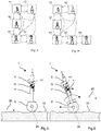
- the tool guide 1 stands, albeit only metastable, if the center of gravity G is vertically above the wheel axle 28 (equilibrium, Fig. 5 ).
- a lateral deflection x is equal to zero.
- the tool guide 1 falls when the center of gravity G is offset from the wheel axle 28 in the lateral direction 33, i.e. the lateral deflection x is not equal to zero ( Fig. 6 ).
- Both the steering system 20 and the propeller 101 have a (center of gravity) sensor 34 for detecting the lateral deflection x of the center of gravity G of the lifting mechanism 7.
- the lateral deflection x of the center of gravity G out of equilibrium results in various measurable variables.
- the lifting mechanism 7 is inclined to gravity; the center of gravity sensor 34 may accordingly include an inclination sensor.
- the falling movement leads to a characteristic acceleration; the center of gravity sensor 34 may include a gyro sensor, an acceleration sensor, a yaw rate sensor, etc. for determining speed, acceleration, yaw rate and/or rotational movement about the wheel axle 28.
- the inclined lifting mechanism 7 exerts a torque on the drive 21; the center of gravity sensor 34 may include a torque sensor, a force sensor, etc. for detecting a torque, a non-vertical force, etc.
- the sensors can detect the quantities listed above based on mechanical, optical, magnetic or electrical effects.
- the steering system 20 and the propeller 101 work together to determine a torque for erecting the lifting mechanism 7 based on the deflection x.
- the steering system 20 may specify a torque proportional to the deflection x.
- the steering system 20 transmits the torque in the form of a control signal to the drive 21 which generates the torque.
- the propeller 101 also calculates the target additional torque which is needed to compensate the torque generated by the drive 21.
- the steering system 20 and the propeller forms a control loop that adjusts the deflection x to zero.
- Control parameters such as the gain factor and the integral component, are preferably adaptable, for example, in order to adapt the target additional torque generated by propeller 101 to the different weight of the hand-held machine tools 6.
- the lifting mechanism 7 is vertically aligned by the engine power of the drive 21. Due to disturbances of the equilibrium, the lifting mechanism 7 can oscillate several times about the vertical alignment in response to the control process. At this moments, the propeller 101 creates an additional torque for counteracting the oscillation. After oscillating, no movement is visible to the user. The torque acting on the lifting mechanism 7 is opposed by the additional torque acting on the wheels 27.
- the statically unstable position of the chassis 8 and the additional self-balancing members are used to align the lifting axis 25 vertically.
- the center of gravity G lies vertically above the wheel axle 28.
- the lifting mechanism 7 is, relative to the wheel axle 28, mounted such that a line passing through the center of gravity G and the working axis 18, is parallel to the lifting axis 25.
- the exemplary lifting mechanism 7 has a balance weight 35 on the mounting 5 to adjust the position 4 of the center of gravity G for different hand-held machine tools 6.
- the balance weight 35 can be locked at different distances from the lifting axis 25.
- the control can adjust the deflection x to a predetermined offset.
- the offset preferably takes into account the placing position of the lifting mechanism 7. Regardless of the height of the lift 7, the dynamic balancing aligns the lifting axis 25 vertically.
- the tool guide 1 can move faster due to the forward force. But it is important to keep the whole tool guide balancing, the forward offset should not be too much, otherwise the tool guide 1 falls over to the ground.
- the propeller 101 can excellently control the dynamic equilibrium.
- the user activates the tool guide 1.
- the controller 9 activates the propeller 101 of the tool guide 1.
- the propeller blades rotate and generate a pulling force, which leads to an torque on the upper portion of the tool guide 1, thereby causing the center of gravity G of the lifting mechanism to deflect a bit from the vertical axis, that is, a deflection x is not zero at this moment.
- Such a deflection would help the tool guide tend to move forwardly. Since the additional torque on the top enables the tool guide 1 to lean fast in a desired direction, the propeller 101 accelerates the tool guide's movement in a desired direction. The propeller 101 needs to calculate the correct target torque which is needed to move forward, and at the same time, the tool guide 1 would not fall over the ground.
- Direction and speed of movement of the chassis 8 are additionally controlled by the propeller 101 of the tool guide 1. It is useful to improves the accuracy of speed and position.
- the additional self-balancing member 100 is a moving mass 102, which is arranged between the mounting 5 and lifting mechanism 7.
- the moving mass 102 can move along the lifting axis 25. Depending on the position of the moving mass 102, it can create a target torque exerting on the wheels for additional balancing the tool guide in the correct position.
- the dynamic balancing ensures a vertical alignment when the wheel axle 28 is horizontal.
- the deflection x is in a level perpendicular to the direction of the wheel axle 28.
- the wheel axle 28 may be inclined to the horizontal plane ( Fig. 7 ).
- the inclination 36 of the wheel axle 28 translates into a similar inclination of the lifting mechanism 7.
- the inclination 36 is in a plane which is spanned by the wheel axle 28 and the vertical axis. The inclination of the wheel axle 28 cannot be directly compensated by the dynamic balancing.
- the inclination 36 is preferably also compensated.
- the exemplary controller 9 provides for triggering the inclination 36 when activating the lifting mode S3.
- the user or an external controller 9 will activate the lifting mode S3 when the tool guide 1 is positioned at the predetermined position 4.
- the compensation can also be triggered in another mode. For example, a specific mode for the compensation can be provided, which is triggered automatically or on request of the user, for example, when reaching the position 4.
- the additional self-balancing member 100 is a moving mass 102. More preferably, the additional self-balancing member 100 is compressed air 103.
- the alignment therefore initially provides for setting the two wheels 27 to the same height.
- the tool guide 1 rotates about a vertical axis, which coincides, for example, with the working axis 18.
- the vertical axis denotes an axis which is perpendicular to the wheel axle 28 and extends substantially along the vertical axis.
- the tool guide 1 is preferably positioned so that the vertical axis passes through the predetermined position 4.
- the moving mass 102 or the compressed air 103 created an additional torque acting on the two wheels 27, which rotates the two wheels at the same speed in the opposite direction 26, as shown in Fig. 8 .
- the tool guide 1 and the tool 11 thus remain at the same position 4.
- the compact design with the small footprint typically allows this rotation even in confined spaces.
- the rotation takes place until the inclination 36 of the wheel axle 28 is equal to zero. Since the tool guide 1 touches the bottom 19 with only two wheels 27, for each position 4 there are at least one location in which all wheels 27 are at the same height.
- An inclination sensor 37 can detect the inclination of the wheel axle 28 with respect to the horizontal plane.
- the inclination sensor 37 can be implemented, for example, by the center of gravity sensor 34 or analogously.
- the moving mass 102 or the compress air 103 balances the lifting mechanism 7 in the vertical lateral direction 26 of the wheel axle 28.
- the additional torque generated by the moving mass 102 or the compressed air 103 exerting on the two wheels 27 acts in the same direction 26 and is typically the same size.
- the additional self-balancing member 100 can work as a complementary system to the steering system 20.
- the steering system includes a console 10 with input elements for driving direction and speed.
- An exemplary console 10 is based on a two-axis joystick.
- Other consoles may include, for example, a steering wheel for the direction of travel and a slider for the speed.
- the console 10 is preferably removable from the tool guide 1.
- a transmission of the control signals generated by the console 10 to the drive 21 is radio-based, optical or cable-based.
- the steering system 20 can detect a pushing or pulling force exerted by the user on the chassis 8. Under the action of the force, the propeller 101 creates an additional force and cause the chassis 8 to tilt in the direction 26 of the pushing or pulling force.
- the steering system 20 and the propeller 101 detects the deflection x of the chassis 8.
- a speed of the chassis 8, for example, may be proportional to the deflection x.
- the tool guide 1 may suspend dynamic balancing when the tool 11 touches the ceiling 3. With the contact point on the ceiling 3, the tool guide 1 can remain static. The tool guide 1 can change to a stop mode S5, in which the wheels 27 are blocked by a brake 53 ( Fig. 9 ). The balancing and the associated slight oscillating movement stops.
- the tool guide 1 has a (contact) sensor 54 which detects a contact with the ceiling 3.
- the tool 11 consumables or the hand-held machine tool 6 touches the ceiling 3.
- the mounting 5 indirectly touches the ceiling 3.
- the contact sensor 54 outputs a (contact) signal to the controller 9, in which it is coded whether the tool 11 is in contact with the ceiling 3.
- the contact sensor 54 can evaluate, for example, the contact pressure of the lifting mechanism 7 or a measure of the contact pressure.
- the contact sensor 54 reports a contact when the contact pressure exceeds a threshold value or a rate of change of the contact pressure exceeds a threshold value.
- the threshold value is preferably dimensioned such that the associated contact pressure force is sufficient to keep the tool guide 1 in a static stable state via the two wheels 27 and the contact point on the ceiling 3.
- the contact sensor 54 may be realized for example by the sensor 49 or an analog sensor 49.
- the controller 9 preferably suspends the balancing of the chassis 8 in case a contact signal is present.
- the controller 9 can delay the suspension until the contact signal is present for a minimum period.
- the steering system 20 checks whether the lifting mechanism 7 is vertically aligned. If the steering system 20 detects a deviation from the vertical orientation, the propeller 101 is activated to apply an additional torque that adjusts the deflection x to zero, ensuring that the lifting mechanism 7 is vertically aligned.
- the chassis 8 preferably has a brake 53.
- the brake 53 is preferably activated as soon as the tool guide 1 is vertically aligned and the contact signal is applied.
- the brake 53 is a parking brake, which permanently blocks the wheels 27 of the chassis 8.
- the tool guide 1 has one or several batteries 32, 55 for supplying electricity.
- the tool guide 1 falls into an (emergency) mode S9 when the battery level 32 55 falls below the emergency level.
- the emergency mode ensures a secure position of the tool guide 1.
- the chassis 8 and the propeller 101 are supplied with power. The user can drive the tool guide 1 to a charging station or another desired location.
Landscapes
- Engineering & Computer Science (AREA)
- Mechanical Engineering (AREA)
- Manipulator (AREA)
- Handcart (AREA)
Abstract
An improved self-aligning tool guide. The tool guide has a mounting, a lifting mechanism and a self-balancing chassis. The mounting is for fixing a hand-held machine tool. The mounting is mounted on the lifting mechanism. The lifting mechanism has a propulsion unit for vertical lifting of the mounting. The self-balancing chassis has two wheels on a wheel axle, a drive coupled with the wheels and a steering system. A center of gravity sensor is mounted to detect a lateral deflection of the center of gravity of the lifting mechanism relative to the wheel axle. The steering is set up to control the drive, to output a torque counteracting the deflection (x). An additional self-balancing member is mounted on the upper portion of the tool guide to deliver an additional torque for balancing the tool guide.
Description
- The invention relates to an improved self-balancing tool guide for the tool.
- Suspended ceilings are a common design element in large buildings, especially in industrial and office buildings. Technical installations, such as electrical installations, ventilation systems, lighting and sound insulation, can be laid between the ceiling of the shell construction and the suspended ceiling and are accessible for subsequent inspection and maintenance. Load-bearing substructures of the installations and the suspended ceiling are fixed with dowels, screws or similar elements anchored in the ceiling of the shell construction. To build the suspended ceiling, holes are drilled in the ceiling of the shell, in which the dowels can be used or the screws can be screwed. A lateral position of the holes is predetermined by the supporting substructure.
- Drilling the holes is time consuming. The user can reach the high-hanging ceiling of the shell construction only with a ladder or scaffolding. The ladder must be placed below the predetermined position, the user climbs up the ladder, drills the hole, descends the ladder, and shifts the ladder to the next position.
-
DE 33 28 582 A1 describes a mobile ceiling drilling and mounting device for the installation of knock-in anchors in a ceiling. The ceiling drill is based on an impact drill, which is mounted on a telescopic column. The telescopic column is suspended oscillating on a trolley. The user can drive the ceiling drill below a desired location, apply the impact drill to the ceiling by means of the column and drill a hole in the ceiling. The impact drill can be controlled via a control cabinet. For transporting over stairwells, the device must be divided into four parts - carriage, telescopic column, impact drill and control cabinet. -
WO2019101482 A1 describes a self-aligning tool guide. The tool guide has a mounting, a lifting mechanism and a chassis. The self-aligning tool guide allows for a very compact and lightweight design by reducing the number of assemblies. The axis of the tool is aligned by the drive control and wheels. In a deflection of the tool from the predetermined direction, the wheels actively exert a counter-torque, which aligns the tool correctly again. This is especially necessary when applying the tool to the ceiling. The dynamic stabilization enables a stable footing of the tool guide already on one wheel or on two wheels. However, such a tool guide system usually is quite high, almost reaching to the ceiling, it is unstable either in driving mode or standing mode. The position of the tool guide system sometimes cannot be very accurately as expected. Also, if the tool guide system moves too fast, there would be highly possible to fall down due to its high gravity center. Therefore, it is necessary to improve the stability, increase the accuracy of the positioning and moving speed. - Accordingly, the primary object of the present invention is to provide an improved self-aligning tool guide. for anchorage in a bore hole that can be used also for heavy loads, that can perfectly balance three functions of the collapsible function, the anti-spinning and setting functions.
- An embodiment of the invention relates to an improved self-aligning tool guide. The tool guide has a mounting, a lifting mechanism and a self-balancing chassis. The mounting is for fixing a hand-held machine tool. The mounting is mounted on the lifting mechanism. The lifting mechanism has a propulsion unit for vertical lifting of the mounting. The self-balancing chassis has two wheels on a wheel axle, a drive coupled with the wheels and a steering system. A center of gravity sensor is mounted to detect a lateral deflection of the center of gravity of the lifting mechanism relative to the wheel axle. The steering is set up to control the drive, to output a torque counteracting the deflection (x). An additional self-balancing member is mounted on the upper portion of the tool guide to deliver an additional torque for balancing the tool guide.
- In one embodiment, the additional self-balancing member calculates the additional torque compensatory counteracting the deflection complementarily. Preferably, the additional self-balancing member creates the additional torque applying to the wheels.
- The axis of the tool is aligned by the drive control and wheels. In a deflection of the tool from the predetermined direction, the wheels were controlled by the drive, and actively exert a counter-torque, which aligns the tool correctly again. The additional self-balancing member work together with the drive, in a deflection of the tool from the predetermined direction, especially an accuracy of the position or moving is needed, the additional self-balancing member actively detect the deflection, and calculate a target additional torque for counteracting the deflection complementarily, then exert the additional counter-torque on upper portion of the tool guide, which aligns the tool correctly again with no movement of the wheels. The dynamic stabilization enables a stable footing of the tool guide already on wheels.
- This is especially necessary when applying the tool to the ceiling. Both floor and ceiling of a shell are wavy and inclined to the horizontal, whereby lateral forces act on the tool. A freely oscillating tool would avoid the lateral forces by a deflection and thus lead to a misalignment of the tool.
- In one embodiment, the additional self-balancing member holds the upper part of the tool guide in upright position. The tool guide usually touches the ground only with the two wheels. An upright standing position is ensured by the additional balancing member. The additional self-balancing member creates an additional force (leading to a counteracting torque), apply this additional torque on top of the tool guide, which can hold the tool guide in upright position, to increase the stability.
- In another embodiment the additional torque created by the additional self-balancing member accelerated the tool guide's movement in a desired direction. Since the additional torque on the top enables the device to lean fast in a desired direction, which is needed to move forward. It is useful for being able to move fast. Therefore, the tool guide improves the accuracy of speed and position when it works.
- In another yet embodiment, preferably, the additional self-balancing member is a propeller. Also, the additional self-balancing member can be a moving mass or compressed air. Anything which can creates force/torque on the upper portion of the tool guide can be used. The self-aligning tool guide allows for a very compact and lightweight design.
- The following description explains the invention with reference to exemplary embodiments and figures. In the figures:
- Fig. 1
- shows a self-aligning tool guide from the front
- Fig. 2
- shows a self-aligning tool guide in a sectional view I-I
- Fig. 3
- shows a self-aligning tool guide when machining a ceiling in a sectional view II
- Fig. 4
- shows a status diagram
- Fig. 5
- shows a diagram explaining the alignment (equilibrium)
- Fig. 6
- shows a diagram explaining the alignment in the forward/backward direction
- Fig. 7
- shows a diagram explaining the alignment in the transverse direction
- Fig. 8
- shows a diagram explaining the alignment in the transverse direction
- Fig. 9
- shows a status diagram
- Identical or functionally identical elements are indicated by the same reference numerals in the figures, unless stated otherwise. Vertical, in the context of this description, denotes a direction parallel to gravity; horizontal denotes a direction or plane perpendicular to gravity.
-
Fig. 1 to Fig. 3 show an exemplary improved self-aligningtool guide 1 for installation work in a shell construction. An assembly of a ventilation pipe requires, for example,several holes 2 in aceiling 3 of the shell construction. Theholes 2 should lie atpredetermined positions 4, e.g. in alignment. Furthermore, theholes 2 should be parallel to each other, for example oriented vertically.Position 4 is entered in a plan, for example. A foreman can mark theposition 4 by color markings on theceiling 3 of the shell construction. Other installation work on theceiling 3 may include setting nails, driving in screws, grinding, etc. -
Fig. 1 to Fig. 3 schematically show an embodiment of the improved self-aligningtool guide 1 Thetool guide 1 has a mounting 5 for a hand-heldmachine tool 6, amotorized lifting mechanism 7, amotorized chassis 8, acontroller 9, aconsole 10 and an additional self-balancingmember 100. As described in the cited patent application documentWO2019/101482 , the user can set up thetool guide 1 with a suitable hand-heldmachine tool 6 and asuitable tool 11 according to the application. Fordrilling holes 2 in a shell construction this would be, for example, an impact drill with ahammer mechanism 12 and a drill with a sintered carbide tip. The hand-heldmachine tool 6 can be used in the mounting 5 on thelifting mechanism 7. Alock 13 secures the hand-heldmachine tool 6 in the mounting 5. Thelock 13 is preferably releasable without tools. In other embodiments, the power tool with the mounting may be 5 be permanently connected, for example, it may be screwed. - The impact drill is just one example of a hand-held
machine tool 6. Other examples are an electric screwdriver, a nail setter, an angle grinder, a glue gun, a paint spray gun, etc. One type of hand-heldmachine tool 6 drives areplaceable tool 11 e.g. the drill, a chisel, a screwdriver bit, a cutting disc, etc. for its function. Another type of hand-heldmachine tool 6 directly processes a consumable, e.g. nails, screws, paint, glue. The hand-heldmachine tools 6 are characterized by an own drive, with which thetool 11 is driven or the consumable is driven or applied. The user does not have to apply manual force for the use of the hand-heldmachine tool 6. The hand-held machine tools are referred to as power tools. Thepower source 14 may be electric or fuel-driven. Examples are an electric motor, an electric pump, a gas-fed combustion chamber, a powder-driven piston, etc. Thepower source 14 is coupled to a (trigger)button 15. When thetrigger button 15 is pressed, thepower source 14 is activated. Thetrigger button 15 is preferably remotely triggered or locked. - The hand-held
machine tool 6 may be a commercially available hand-heldmachine tool 6. The hand-heldmachine tool 6 has ahandle 16 and typically ahousing portion 17 for fastening an additional handle. The hand-heldmachine tool 6 may be formed without a handle. The mounting 5 may also be designed for non-handheld machine tools. - The hand-held
machine tool 6 has a workingaxis 18 defined by its structure A tip of thetool 11 or a tip of the consumable lies on the workingaxis 18 The tip is moved along the workingaxis 18. The tip first touches the surface to be machined, e.g. theceiling 3. - An additional self-balancing
member 100 is mounted on the upper portion of the tool guide. For example, theadditional member 100 could be mounted between the mounting 5 and thelifting mechanism 7. Preferably, the additional self-balancing member is connected to the lifting mechanism and can move along a fixedlifting axis 25 when thelifting mechanism 7 raises or lowers the mounting 5. Preferably, the additional balancing member is rigidly connected to the top of thelifting mechanism 7. The additional self-balancingmember 100 can create an additional force (leading to a torque) on upper part of thetool guide 1, exert the torque on the wheels. This additional self-balancingmember 100 can hold thetool guide 1 in the upright position, which is needed to increase the stability. It is also useful for being able to move fast. - Preferably, the additional self-balancing
member 100 is apropeller 101. Alternatively, it also can be a moving mass or compressed air. Another example of the additional self-balancing member is a reaction wheel. Generally, anything which creates force/torque on top can be used. In one exemplary embodiment, thepropeller 101 is rigidly connected to thetool guide 1, between the mounting 5 and thelifting mechanism 7. Also, thepropeller 101 is electronically connected to thesteering system 20. As it is well known, the propeller can create a force when it is activated. - A status diagram of the
tool guide 1 is shown inFig. 4 . The user activates thetool guide 1 by means of theconsole 10. Thechassis 8 is in a (driving) mode S1 in which the user can move thetool guide 1 through the room on thefloor 19. Thecontroller 9 activates asteering system 20 of thetool guide 1. The user can set the direction of travel and speed via theconsole 10. The user steers thetool guide 1 to one of the marked positions 4. Thechassis 8 has adrive 21 which moves thechassis 8 over theground 19 on its own power. Direction and speed of movement of thechassis 8 are controlled by thesteering system 20 of thetool guide 1. However, the positioning accuracy and speed that can be reached by controlling thesteering system 20 is limited. Therefore, beside of thesteering system 20, thepropeller 101 is also activated by the controller and creates an additional force leading to an additional torque, then exert the correct target torque to thewheels 27. This is useful for being able to move fast, since the torque on top enables the device to lean fast in a desired direction, which is needed to move forward. - At the
marked position 4 the user stops thetool guide 1. Via theconsole 10, the user puts thechassis 8 in a (standing) mode S2. Thecontroller 9 locks thesteering system 20 for the user or deactivates thesteering system 20. Thesteering system 20 ignores specifications for speed and direction of travel via theconsole 10. Thetool guide 1 remains in the currently occupiedposition 4. Thesteering system 20 can detect thecurrent position 4. If thechassis 8 leaves thecurrent position 4 or is shifted from this, thesteering system 20 automatically generates control signals to drive thechassis 8 back to the detectedposition 4. In a (standing) mode S2, thepropeller 101 also help thechassis 8 hole the whole device oftool guide 1 in upright position. If a sensor detects there is any deflection or deviation between thetool guide 1 and themarked position 4, thepropeller 101 is activated, and then calculate a target torque needed for complementarily counteracting the deflection or deviation, exert the torque on thewheels 27, thereby holding the tool guide in the exactly correct position in upright direction allowing no movements of thewheels 27. - The user can activate a (lifting) mode S3 via the
console 10 in order to lift the hand-heldmachine tool 6 with thelifting mechanism 7. Thecontroller 9 forces the standing mode S2 for thechassis 8 before the lift mode can be activated. Thecontroller 9 can delay the activation of the lift mode until thechassis 8 is stationary. In the lifting mode, acontrol station 22 is enabled or activated for the user. The user can specifymovement direction 23 i.e. up or down, lifting speed and position of thelifting mechanism 7 via theconsole 10. The mounting 5 is moved by thelifting mechanism 7 accordingly. Thecontrol station 22 controls apropulsion unit 24 of thelifting mechanism 7, taking into account the predetermined vertical direction of movement and lifting speed specified via theconsole 10. Thelifting mechanism 7 raises or lowers the mounting 5 and, optionally, the hand-heldmachine tool 6 inserted therein, along a fixedlifting axis 25. Thelifting mechanism 7 is limited to a single-axis, translational motion on the liftingaxis 25. In one embodiment, thepropeller 101 is rigidly connected to the top of thelifting mechanism 7. Therefore, thepropeller 101 would create different torque applying to thewheels 27 depending on the moving of thelifting mechanism 7. - The working
axis 18 of the hand-heldmachine tool 6 is parallel to the liftingaxis 25. In one embodiment, the construction of the mounting 5 forces the parallel alignment. The hand-heldmachine tool 6 can be used, for example, due to a fit of the mounting 5 to a housing of the hand-heldmachine tool 6, in only one defined manner in the mounting 5. In one embodiment, the mounting 5 can be pivoted about the (pivot)axis 25 inclined to the lifting axis, in order to align the alignment of thework axis 18 to the liftingaxis 25. - An alignment of the lifting
axis 25 and thus the workingaxis 18 relative to theceiling 3 is done dynamically by thechassis 8 and theadditional balancing member 100. Thechassis 8 aligns the liftingaxis 25 vertically, i.e. parallel to gravity. - The hand-held
machine tool 6 can preferably switch on thecontrol console 22. Thetool 11 can machine theceiling 3, for example, drill ahole 2. Thecontroller 9 may have a (machining) mode S4, which automatically controls thepropulsion unit 24 of thelifting mechanism 7 during the work on theceiling 3. The machining mode can be activated manually, for example, on theconsole 10. In the processing mode, thecontrol station 22 adapts the lifting speed of thelifting mechanism 7 to a machining progress of thetool 11. Thelifting mechanism 7 and thetool 11 can be protected from excessive loads. A machining target, e.g. a hole depth, can be specified on thecontrol station 22. After reaching the machining target, thecontrol console 22 can automatically stop thepropulsion unit 24. In addition, thecontrol console 22 can automatically lower thelifting mechanism 7 so far that thetool 11 is out of engagement with theceiling 3. - In one exemplary embodiment the
propeller 101 also create an additional torque to compensate the oscillation caused by working process in the machining mode S4. Preferably, thepropeller 101 is rigidly connected to thelifting mechanism 7, for example, the side of the top of thelifting mechanism 7. Due to disturbances of the equilibrium, thelifting mechanism 7 can oscillate several times about the vertical alignment in response to the control process. Thepropeller 101 creates an additional torque to the wheels. The torque acting on thelifting mechanism 7 is opposed by the additional torque acting on thewheels 27. The oscillating of thelifting mechanism 7 is damped by the additional self-balancingmember 100, that is,propeller 101. - The user can now move the
tool guide 1 to a nextmarked position 4. The user switches thetool guide 1 into the driving mode S1. Thecontrol station 22 is locked for the user. The hand-heldmachine tool 6 is forcibly turned off. Thetool guide 1 can check before starting whether thetool 11 is still in engagement with theceiling 3. For example, thesteering system 20 moves thechassis 8 by a small predetermined distance in adirection 26 and checks whether a counteracting torque acts on thechassis 8. Thesteering system 20 moves thechassis 8 back to theprevious position 4, changes to the standing mode and causes thecontrol station 22 to lower thelifting mechanism 7. - The
chassis 8 is the first self-balancing system for thetool guide 1. Thechassis 8 has twowheels 27 coupled with thedrive 21. The twowheels 27 are mounted mutually offset on a transverse axis orwheel axle 28. Thewheel axle 28 extends through the middle of the twowheels 27. Thewheels 27 may be parallel to each other; or thewheels 27 are inclined by a few degrees to each other due to a camber and/or a toe angle. The twowheels 27 essentially rotate about thewheel axle 28. Each of thewheels 27 is coupled to thedrive 21. Thedrive 21 may include twoelectric motors 29, for example. Thewheels 27 each sit directly on arotor 30, one of theelectric motors 29. Alternatively, thewheels 27 may be coupled via clutches and gears to a centralelectric motor 29. Thedrive 21 exerts on the wheels 27 a torque acting around thewheel axle 28. The rotationally drivenwheels 27 move thechassis 8 over theground 19. Thechassis 8 moves straight ahead when the twowheels 27 rotate at the same speed. Thewheels 27 can be driven individually by thedrive 21. Different torque and different speed of thewheels 27 cause thechassis 8 to drive around a bend. Preferably, thewheels 27 can be driven in opposite directions to rotate thechassis 8 about its vertical axis. Thedrive 21 receives control signals for speed and torque of the twowheels 27 from thesteering system 20. Thesteering system 20 generates the control signals in response to predetermined steering movements, e.g. to the steering movements specified by the user. - The
propeller 101 is an exemplary embodiment of the additional self-balancingmember 100, which works together with the self-balancing chassis to achieve an improved controllability of the accuracy of positioning and speed. Thepropeller 101 may have a sensor for detecting the output torque and speed of thewheels 27. The acquired measurement data can be transmitted to thepropeller 101 in order to correct the deviations from the steering movement of thechassis 8. - The
chassis 8 and thetool guide 1 are on thefloor 19 only with the twowheels 27. The two points of contact P1 P2 are on a line parallel to thewheel axle 28. For a statically stable state, there is no third point of contact with theground 19 outside the line. Thetool guide 1 would fall over without a countermeasure. The additional self-balancingmember 10 help thesteering system 20 achieve a dynamic equilibrium by permanently balancing the center of gravity G of thelifting mechanism 7. Based on detection of the center of gravity G, thepropeller 101 generates a counteracting torque acting on the wheels to correct the deflection or deviation. - The
lifting mechanism 7 is mounted on thechassis 8. Thelifting mechanism 7 is stationary relative to thechassis 8, in particular, thelifting mechanism 7 is immovable with respect to thedrive 21 and thewheel axle 28. Thelifting mechanism 7 is preferably rigidly connected to astator 31 of thedrive 21. Thedrive 21 generates a torque and a retroactive torque of the same size and opposite direction of rotation in pairs. The torque acts on thewheels 27 via therotor 30 of thedrive 21. The retroactive torque acts via thestator 31 of thedrive 21 on thelifting mechanism 7. - The weight of the
tool guide 1 is composed of the weight of thechassis 8 and the weight of thelifting mechanism 7 together. The weight of the hand-heldmachine tool 6 and thepropeller 101 is, to simplify, added to the weight of thelifting mechanism 7. The center of gravity of thechassis 8 is approximately on thewheel axle 28. Thewheels 27 thedrive 21 andbatteries 32 are mounted symmetrically about thewheel axle 28. The center of gravity G of thelifting mechanism 7 is above thewheel axle 28. Thetool guide 1 stands, albeit only metastable, if the center of gravity G is vertically above the wheel axle 28 (equilibrium,Fig. 5 ). A lateral deflection x is equal to zero. Thetool guide 1 falls when the center of gravity G is offset from thewheel axle 28 in the lateral direction 33, i.e. the lateral deflection x is not equal to zero (Fig. 6 ). - Both the
steering system 20 and thepropeller 101 have a (center of gravity) sensor 34 for detecting the lateral deflection x of the center of gravity G of thelifting mechanism 7. The lateral deflection x of the center of gravity G out of equilibrium results in various measurable variables. Thelifting mechanism 7 is inclined to gravity; the center of gravity sensor 34 may accordingly include an inclination sensor. The falling movement leads to a characteristic acceleration; the center of gravity sensor 34 may include a gyro sensor, an acceleration sensor, a yaw rate sensor, etc. for determining speed, acceleration, yaw rate and/or rotational movement about thewheel axle 28. Theinclined lifting mechanism 7 exerts a torque on thedrive 21; the center of gravity sensor 34 may include a torque sensor, a force sensor, etc. for detecting a torque, a non-vertical force, etc. The sensors can detect the quantities listed above based on mechanical, optical, magnetic or electrical effects. - The
steering system 20 and thepropeller 101 work together to determine a torque for erecting thelifting mechanism 7 based on the deflection x. For example, thesteering system 20 may specify a torque proportional to the deflection x. Thesteering system 20 transmits the torque in the form of a control signal to thedrive 21 which generates the torque. At the same time, thepropeller 101 also calculates the target additional torque which is needed to compensate the torque generated by thedrive 21. Thesteering system 20 and the propeller forms a control loop that adjusts the deflection x to zero. Control parameters, such as the gain factor and the integral component, are preferably adaptable, for example, in order to adapt the target additional torque generated bypropeller 101 to the different weight of the hand-heldmachine tools 6. - The
lifting mechanism 7 is vertically aligned by the engine power of thedrive 21. Due to disturbances of the equilibrium, thelifting mechanism 7 can oscillate several times about the vertical alignment in response to the control process. At this moments, thepropeller 101 creates an additional torque for counteracting the oscillation. After oscillating, no movement is visible to the user. The torque acting on thelifting mechanism 7 is opposed by the additional torque acting on thewheels 27. - The statically unstable position of the
chassis 8 and the additional self-balancing members are used to align the liftingaxis 25 vertically. In the dynamic equilibrium, the center of gravity G lies vertically above thewheel axle 28. Thelifting mechanism 7 is, relative to thewheel axle 28, mounted such that a line passing through the center of gravity G and the workingaxis 18, is parallel to the liftingaxis 25. Theexemplary lifting mechanism 7 has a balance weight 35 on the mounting 5 to adjust theposition 4 of the center of gravity G for different hand-heldmachine tools 6. The balance weight 35 can be locked at different distances from the liftingaxis 25. Instead of a balance weight 35, the control can adjust the deflection x to a predetermined offset. The offset preferably takes into account the placing position of thelifting mechanism 7. Regardless of the height of thelift 7, the dynamic balancing aligns the liftingaxis 25 vertically. - Preferably, in the dynamic equilibrium, if the center of gravity G lies a bit forwardly above the
wheel axle 28, thetool guide 1 can move faster due to the forward force. But it is important to keep the whole tool guide balancing, the forward offset should not be too much, otherwise thetool guide 1 falls over to the ground. Thepropeller 101 can excellently control the dynamic equilibrium. The user activates thetool guide 1. Thecontroller 9 activates thepropeller 101 of thetool guide 1. The propeller blades rotate and generate a pulling force, which leads to an torque on the upper portion of thetool guide 1, thereby causing the center of gravity G of the lifting mechanism to deflect a bit from the vertical axis, that is, a deflection x is not zero at this moment. Such a deflection would help the tool guide tend to move forwardly. Since the additional torque on the top enables thetool guide 1 to lean fast in a desired direction, thepropeller 101 accelerates the tool guide's movement in a desired direction. Thepropeller 101 needs to calculate the correct target torque which is needed to move forward, and at the same time, thetool guide 1 would not fall over the ground. Direction and speed of movement of thechassis 8 are additionally controlled by thepropeller 101 of thetool guide 1. It is useful to improves the accuracy of speed and position. - In one exemplary embodiment, the additional self-balancing
member 100 is a movingmass 102, which is arranged between the mounting 5 andlifting mechanism 7. The movingmass 102 can move along the liftingaxis 25. Depending on the position of the movingmass 102, it can create a target torque exerting on the wheels for additional balancing the tool guide in the correct position. - The dynamic balancing ensures a vertical alignment when the
wheel axle 28 is horizontal. The deflection x is in a level perpendicular to the direction of thewheel axle 28. For anuneven floor 19 orinclined floor 19, thewheel axle 28 may be inclined to the horizontal plane (Fig. 7 ). Theinclination 36 of thewheel axle 28 translates into a similar inclination of thelifting mechanism 7. Theinclination 36 is in a plane which is spanned by thewheel axle 28 and the vertical axis. The inclination of thewheel axle 28 cannot be directly compensated by the dynamic balancing. - For machining the
ceiling 3, theinclination 36 is preferably also compensated. Theexemplary controller 9 provides for triggering theinclination 36 when activating the lifting mode S3. The user or anexternal controller 9 will activate the lifting mode S3 when thetool guide 1 is positioned at thepredetermined position 4. The compensation can also be triggered in another mode. For example, a specific mode for the compensation can be provided, which is triggered automatically or on request of the user, for example, when reaching theposition 4. - It is advantageous to use the additional self-balancing
member 100 to compensate such aninclination 36. Preferably, the additional self-balancingmember 100 is a movingmass 102. More preferably, the additional self-balancingmember 100 is compressedair 103. The alignment therefore initially provides for setting the twowheels 27 to the same height. Thetool guide 1 rotates about a vertical axis, which coincides, for example, with the workingaxis 18. The vertical axis denotes an axis which is perpendicular to thewheel axle 28 and extends substantially along the vertical axis. Thetool guide 1 is preferably positioned so that the vertical axis passes through thepredetermined position 4. The movingmass 102 or thecompressed air 103 created an additional torque acting on the twowheels 27, which rotates the two wheels at the same speed in theopposite direction 26, as shown inFig. 8 . Thetool guide 1 and thetool 11 thus remain at thesame position 4. The compact design with the small footprint typically allows this rotation even in confined spaces. The rotation takes place until theinclination 36 of thewheel axle 28 is equal to zero. Since thetool guide 1 touches the bottom 19 with only twowheels 27, for eachposition 4 there are at least one location in which allwheels 27 are at the same height. Aninclination sensor 37 can detect the inclination of thewheel axle 28 with respect to the horizontal plane. Theinclination sensor 37 can be implemented, for example, by the center of gravity sensor 34 or analogously. The movingmass 102 or thecompress air 103 balances thelifting mechanism 7 in the verticallateral direction 26 of thewheel axle 28. The additional torque generated by the movingmass 102 or thecompressed air 103 exerting on the twowheels 27 acts in thesame direction 26 and is typically the same size. - The additional self-balancing
member 100 can work as a complementary system to thesteering system 20. For example, the steering system includes aconsole 10 with input elements for driving direction and speed. Anexemplary console 10 is based on a two-axis joystick. Other consoles may include, for example, a steering wheel for the direction of travel and a slider for the speed. Theconsole 10 is preferably removable from thetool guide 1. A transmission of the control signals generated by theconsole 10 to thedrive 21 is radio-based, optical or cable-based. Thesteering system 20 can detect a pushing or pulling force exerted by the user on thechassis 8. Under the action of the force, thepropeller 101 creates an additional force and cause thechassis 8 to tilt in thedirection 26 of the pushing or pulling force. Thesteering system 20 and thepropeller 101 detects the deflection x of thechassis 8. A speed of thechassis 8, for example, may be proportional to the deflection x. - In one embodiment, the
tool guide 1 may suspend dynamic balancing when thetool 11 touches theceiling 3. With the contact point on theceiling 3, thetool guide 1 can remain static. Thetool guide 1 can change to a stop mode S5, in which thewheels 27 are blocked by a brake 53 (Fig. 9 ). The balancing and the associated slight oscillating movement stops. - The
tool guide 1 has a (contact)sensor 54 which detects a contact with theceiling 3. Typically, thetool 11 consumables or the hand-heldmachine tool 6 touches theceiling 3. The mounting 5 indirectly touches theceiling 3. Thecontact sensor 54 outputs a (contact) signal to thecontroller 9, in which it is coded whether thetool 11 is in contact with theceiling 3. Thecontact sensor 54 can evaluate, for example, the contact pressure of thelifting mechanism 7 or a measure of the contact pressure. Thecontact sensor 54 reports a contact when the contact pressure exceeds a threshold value or a rate of change of the contact pressure exceeds a threshold value. The threshold value is preferably dimensioned such that the associated contact pressure force is sufficient to keep thetool guide 1 in a static stable state via the twowheels 27 and the contact point on theceiling 3. Thecontact sensor 54 may be realized for example by thesensor 49 or ananalog sensor 49. - The
controller 9 preferably suspends the balancing of thechassis 8 in case a contact signal is present. Thecontroller 9 can delay the suspension until the contact signal is present for a minimum period. When the contact signal is present, thesteering system 20 checks whether thelifting mechanism 7 is vertically aligned. If thesteering system 20 detects a deviation from the vertical orientation, thepropeller 101 is activated to apply an additional torque that adjusts the deflection x to zero, ensuring that thelifting mechanism 7 is vertically aligned. - The
chassis 8 preferably has a brake 53. The brake 53 is preferably activated as soon as thetool guide 1 is vertically aligned and the contact signal is applied. The brake 53 is a parking brake, which permanently blocks thewheels 27 of thechassis 8. - The
tool guide 1 has one orseveral batteries tool guide 1 falls into an (emergency) mode S9 when thebattery level 32 55 falls below the emergency level. The emergency mode ensures a secure position of thetool guide 1. Thechassis 8 and thepropeller 101 are supplied with power. The user can drive thetool guide 1 to a charging station or another desired location.
Claims (10)
- An improved self-aligning tool guide (1) with:a mounting (5) for fixing a hand-held machine tool (6),a lifting mechanism (7), on which the mounting (5) is mounted and wherein the lifting mechanism (7) has a propulsion unit (24) for lifting the mounting (5) parallel to a lifting axis (25),a self-balancing chassis (8), which has two wheels (27) on a wheel axle (28), a drive (21) coupled with the wheels (27) and a steering system (20),a center of gravity sensor (34) for detecting a lateral deflection (x) of the center of gravity (G) of the lifting mechanism (7) relative to the wheel axle (28), the steering (20) is set up to control the drive (21), to output a torque counteracting the deflection (x),wherein an additional self-balancing member (100) is mounted on the upper portion of the tool guide (1), to deliver an additional torque for balancing the tool guide (1).
- An improved self-aligning tool guide (1) according to claim 1, characterized in that the additional self-balancing member (100) calculates the additional torque for counteracting the deflection (x) complementarily.
- An improved self-aligning tool guide (1) according to claim 2, characterized in that the additional self-balancing member (100) creates the additional torque applying to the wheels (20).
- An improved self-aligning tool guide (1) according to claim 3, characterized in that the additional torque created by the additional self-balancing member (100) accelerates the tool guide's movement in a desired direction.
- An improved self-aligning tool guide (1) according to claim 3, characterized in that the additional torque created by the additional self-balancing member (100) holds the tool guide (1) in upright position.
- An improved self-aligning tool guide (1) according to any one of the preceding claims, characterized in that the additional self-balancing member (100) is a propeller.
- An improved self-aligning tool guide (1) according to any one of the preceding claims, characterized in that the additional self-balancing member (100) is a moving mass.
- An improved self-aligning tool guide (1) according to any one of the preceding claims, characterized in that the additional self-balancing member (100) is compressed air.
- An improved self-aligning tool guide (1) according to any one of the preceding claims, characterized in that the additional self-balancing member (100) is mounted between the mouting (5) and the lifting mechanism (7).
- An improved self-aligning tool guide (1) according to any one of the preceding claims, characterized in that the lifting mechanism (7) is limited to a single-axis, translational movement along the lifting axis (25).
Priority Applications (4)
| Application Number | Priority Date | Filing Date | Title |
|---|---|---|---|
| EP19209470.4A EP3822039A1 (en) | 2019-11-15 | 2019-11-15 | Improved self-balancing tool guide |
| EP20800940.7A EP4058253A1 (en) | 2019-11-15 | 2020-11-06 | Improved self-balancing tool guide |
| PCT/EP2020/081293 WO2021094218A1 (en) | 2019-11-15 | 2020-11-06 | Improved self-balancing tool guide |
| US17/775,209 US20220379457A1 (en) | 2019-11-15 | 2020-11-06 | Improved Self-Balancing Tool Guide |
Applications Claiming Priority (1)
| Application Number | Priority Date | Filing Date | Title |
|---|---|---|---|
| EP19209470.4A EP3822039A1 (en) | 2019-11-15 | 2019-11-15 | Improved self-balancing tool guide |
Publications (1)
| Publication Number | Publication Date |
|---|---|
| EP3822039A1 true EP3822039A1 (en) | 2021-05-19 |
Family
ID=68583209
Family Applications (2)
| Application Number | Title | Priority Date | Filing Date |
|---|---|---|---|
| EP19209470.4A Withdrawn EP3822039A1 (en) | 2019-11-15 | 2019-11-15 | Improved self-balancing tool guide |
| EP20800940.7A Withdrawn EP4058253A1 (en) | 2019-11-15 | 2020-11-06 | Improved self-balancing tool guide |
Family Applications After (1)
| Application Number | Title | Priority Date | Filing Date |
|---|---|---|---|
| EP20800940.7A Withdrawn EP4058253A1 (en) | 2019-11-15 | 2020-11-06 | Improved self-balancing tool guide |
Country Status (3)
| Country | Link |
|---|---|
| US (1) | US20220379457A1 (en) |
| EP (2) | EP3822039A1 (en) |
| WO (1) | WO2021094218A1 (en) |
Families Citing this family (3)
| Publication number | Priority date | Publication date | Assignee | Title |
|---|---|---|---|---|
| EP3488974A1 (en) | 2017-11-23 | 2019-05-29 | HILTI Aktiengesellschaft | Self-aligning tool guide |
| EP3488978A1 (en) * | 2017-11-23 | 2019-05-29 | HILTI Aktiengesellschaft | Self-aligning tool guide |
| EP3488977A1 (en) | 2017-11-23 | 2019-05-29 | HILTI Aktiengesellschaft | Self-aligning tool guide |
Citations (6)
| Publication number | Priority date | Publication date | Assignee | Title |
|---|---|---|---|---|
| US3917200A (en) * | 1973-12-14 | 1975-11-04 | Jay Johnson | Pneumatic boom support for hand tools |
| DE3328582A1 (en) | 1982-09-27 | 1984-03-29 | Siemens AG, 1000 Berlin und 8000 München | Mobile ceiling-drilling and assembly appliance for impact plugs |
| US20040231903A1 (en) * | 2003-05-23 | 2004-11-25 | Shayan Shaahin Sean | Supplementary propulsion backpack and methods of use |
| KR20150012933A (en) * | 2013-07-26 | 2015-02-04 | 현대중공업 주식회사 | Balance maintaining apparatus |
| EP3488977A1 (en) * | 2017-11-23 | 2019-05-29 | HILTI Aktiengesellschaft | Self-aligning tool guide |
| WO2019101482A1 (en) | 2017-11-23 | 2019-05-31 | Hilti Aktiengesellschaft | Self-aligning tool guide |
Family Cites Families (12)
| Publication number | Priority date | Publication date | Assignee | Title |
|---|---|---|---|---|
| US3825075A (en) * | 1973-06-18 | 1974-07-23 | R Mee | Drill assembly |
| US5137235A (en) * | 1990-08-29 | 1992-08-11 | U-Haul International, Inc. | Inverted angle drill |
| US20170157727A1 (en) * | 2010-04-15 | 2017-06-08 | J. Reed Felton | Dust collection assembly for use with universal drill stand |
| DE102010030219A1 (en) * | 2010-06-17 | 2011-12-22 | Hilti Aktiengesellschaft | Device for guiding a hand tool |
| GB201419182D0 (en) * | 2014-10-28 | 2014-12-10 | Nlink As | Mobile robotic drilling apparatus and method for drilling ceillings and walls |
| US10245715B2 (en) * | 2015-12-28 | 2019-04-02 | Peter Justin Merello | Overhead drill and anchor press |
| US11890737B2 (en) * | 2015-12-28 | 2024-02-06 | Peter Justin Merello | Overhead drill and anchor press |
| US10279480B1 (en) * | 2016-10-21 | 2019-05-07 | X Development Llc | Sensor fusion |
| EP3488978A1 (en) * | 2017-11-23 | 2019-05-29 | HILTI Aktiengesellschaft | Self-aligning tool guide |
| EP3613544A1 (en) * | 2018-08-22 | 2020-02-26 | Hilti Aktiengesellschaft | Mobile construction robot |
| US20200086400A1 (en) * | 2018-09-17 | 2020-03-19 | J. Reed Felton | Method for engaging a drill trigger on a drill as it is advanced toward the ceiling with a drill apparatus |
| US20210402538A1 (en) * | 2020-06-30 | 2021-12-30 | Gulfstream Aerospace Corporation | Apparatus and method for holding and/or using a tool |
-
2019
- 2019-11-15 EP EP19209470.4A patent/EP3822039A1/en not_active Withdrawn
-
2020
- 2020-11-06 US US17/775,209 patent/US20220379457A1/en not_active Abandoned
- 2020-11-06 EP EP20800940.7A patent/EP4058253A1/en not_active Withdrawn
- 2020-11-06 WO PCT/EP2020/081293 patent/WO2021094218A1/en not_active Ceased
Patent Citations (6)
| Publication number | Priority date | Publication date | Assignee | Title |
|---|---|---|---|---|
| US3917200A (en) * | 1973-12-14 | 1975-11-04 | Jay Johnson | Pneumatic boom support for hand tools |
| DE3328582A1 (en) | 1982-09-27 | 1984-03-29 | Siemens AG, 1000 Berlin und 8000 München | Mobile ceiling-drilling and assembly appliance for impact plugs |
| US20040231903A1 (en) * | 2003-05-23 | 2004-11-25 | Shayan Shaahin Sean | Supplementary propulsion backpack and methods of use |
| KR20150012933A (en) * | 2013-07-26 | 2015-02-04 | 현대중공업 주식회사 | Balance maintaining apparatus |
| EP3488977A1 (en) * | 2017-11-23 | 2019-05-29 | HILTI Aktiengesellschaft | Self-aligning tool guide |
| WO2019101482A1 (en) | 2017-11-23 | 2019-05-31 | Hilti Aktiengesellschaft | Self-aligning tool guide |
Also Published As
| Publication number | Publication date |
|---|---|
| EP4058253A1 (en) | 2022-09-21 |
| WO2021094218A1 (en) | 2021-05-20 |
| US20220379457A1 (en) | 2022-12-01 |
Similar Documents
| Publication | Publication Date | Title |
|---|---|---|
| US11745327B2 (en) | Self-aligning tool guide | |
| US11673252B2 (en) | Self-aligning tool guide | |
| JP7407835B2 (en) | Auto alignment tool guide | |
| US11478918B2 (en) | Self-aligning tool guide | |
| US20220379457A1 (en) | Improved Self-Balancing Tool Guide | |
| JP7590375B2 (en) | Portable robotic drilling device and method for drilling holes in ceilings and walls | |
| WO2012021732A1 (en) | Brick laying system | |
| EP4132751B1 (en) | Levelling system | |
| EP3713715B1 (en) | Self-aligning tool guide | |
| RU2752349C1 (en) | Automated moving machine | |
| WO2019101482A1 (en) | Self-aligning tool guide | |
| US20240246229A1 (en) | Construction robot having a lifting device and method for performing work on a building element | |
| AU2024212166A1 (en) | Method for controlling a construction robot, and construction robot |
Legal Events
| Date | Code | Title | Description |
|---|---|---|---|
| PUAI | Public reference made under article 153(3) epc to a published international application that has entered the european phase |
Free format text: ORIGINAL CODE: 0009012 |
|
| STAA | Information on the status of an ep patent application or granted ep patent |
Free format text: STATUS: THE APPLICATION HAS BEEN PUBLISHED |
|
| AK | Designated contracting states |
Kind code of ref document: A1 Designated state(s): AL AT BE BG CH CY CZ DE DK EE ES FI FR GB GR HR HU IE IS IT LI LT LU LV MC MK MT NL NO PL PT RO RS SE SI SK SM TR |
|
| STAA | Information on the status of an ep patent application or granted ep patent |
Free format text: STATUS: THE APPLICATION IS DEEMED TO BE WITHDRAWN |
|
| 18D | Application deemed to be withdrawn |
Effective date: 20211120 |