EP3822012A1 - Techniques and assemblies for joining components using solid retainer materials - Google Patents
Techniques and assemblies for joining components using solid retainer materials Download PDFInfo
- Publication number
- EP3822012A1 EP3822012A1 EP20202470.9A EP20202470A EP3822012A1 EP 3822012 A1 EP3822012 A1 EP 3822012A1 EP 20202470 A EP20202470 A EP 20202470A EP 3822012 A1 EP3822012 A1 EP 3822012A1
- Authority
- EP
- European Patent Office
- Prior art keywords
- component
- solid retainer
- mechanical interlock
- solid
- joint region
- Prior art date
- Legal status (The legal status is an assumption and is not a legal conclusion. Google has not performed a legal analysis and makes no representation as to the accuracy of the status listed.)
- Pending
Links
Images






Classifications
-
- B—PERFORMING OPERATIONS; TRANSPORTING
- B23—MACHINE TOOLS; METAL-WORKING NOT OTHERWISE PROVIDED FOR
- B23K—SOLDERING OR UNSOLDERING; WELDING; CLADDING OR PLATING BY SOLDERING OR WELDING; CUTTING BY APPLYING HEAT LOCALLY, e.g. FLAME CUTTING; WORKING BY LASER BEAM
- B23K35/00—Rods, electrodes, materials, or media, for use in soldering, welding, or cutting
- B23K35/02—Rods, electrodes, materials, or media, for use in soldering, welding, or cutting characterised by mechanical features, e.g. shape
- B23K35/0255—Rods, electrodes, materials, or media, for use in soldering, welding, or cutting characterised by mechanical features, e.g. shape for use in welding
- B23K35/0294—Consumable guides
-
- B—PERFORMING OPERATIONS; TRANSPORTING
- B22—CASTING; POWDER METALLURGY
- B22F—WORKING METALLIC POWDER; MANUFACTURE OF ARTICLES FROM METALLIC POWDER; MAKING METALLIC POWDER; APPARATUS OR DEVICES SPECIALLY ADAPTED FOR METALLIC POWDER
- B22F7/00—Manufacture of composite layers, workpieces, or articles, comprising metallic powder, by sintering the powder, with or without compacting wherein at least one part is obtained by sintering or compression
- B22F7/06—Manufacture of composite layers, workpieces, or articles, comprising metallic powder, by sintering the powder, with or without compacting wherein at least one part is obtained by sintering or compression of composite workpieces or articles from parts, e.g. to form tipped tools
- B22F7/062—Manufacture of composite layers, workpieces, or articles, comprising metallic powder, by sintering the powder, with or without compacting wherein at least one part is obtained by sintering or compression of composite workpieces or articles from parts, e.g. to form tipped tools involving the connection or repairing of preformed parts
- B22F7/064—Manufacture of composite layers, workpieces, or articles, comprising metallic powder, by sintering the powder, with or without compacting wherein at least one part is obtained by sintering or compression of composite workpieces or articles from parts, e.g. to form tipped tools involving the connection or repairing of preformed parts using an intermediate powder layer
-
- B—PERFORMING OPERATIONS; TRANSPORTING
- B23—MACHINE TOOLS; METAL-WORKING NOT OTHERWISE PROVIDED FOR
- B23K—SOLDERING OR UNSOLDERING; WELDING; CLADDING OR PLATING BY SOLDERING OR WELDING; CUTTING BY APPLYING HEAT LOCALLY, e.g. FLAME CUTTING; WORKING BY LASER BEAM
- B23K1/00—Soldering, e.g. brazing, or unsoldering
- B23K1/0008—Soldering, e.g. brazing, or unsoldering specially adapted for particular articles or work
- B23K1/0018—Brazing of turbine parts
-
- B—PERFORMING OPERATIONS; TRANSPORTING
- B23—MACHINE TOOLS; METAL-WORKING NOT OTHERWISE PROVIDED FOR
- B23K—SOLDERING OR UNSOLDERING; WELDING; CLADDING OR PLATING BY SOLDERING OR WELDING; CUTTING BY APPLYING HEAT LOCALLY, e.g. FLAME CUTTING; WORKING BY LASER BEAM
- B23K35/00—Rods, electrodes, materials, or media, for use in soldering, welding, or cutting
- B23K35/02—Rods, electrodes, materials, or media, for use in soldering, welding, or cutting characterised by mechanical features, e.g. shape
- B23K35/0222—Rods, electrodes, materials, or media, for use in soldering, welding, or cutting characterised by mechanical features, e.g. shape for use in soldering or brazing
- B23K35/0244—Powders, particles or spheres; Preforms made therefrom
-
- B—PERFORMING OPERATIONS; TRANSPORTING
- B23—MACHINE TOOLS; METAL-WORKING NOT OTHERWISE PROVIDED FOR
- B23K—SOLDERING OR UNSOLDERING; WELDING; CLADDING OR PLATING BY SOLDERING OR WELDING; CUTTING BY APPLYING HEAT LOCALLY, e.g. FLAME CUTTING; WORKING BY LASER BEAM
- B23K35/00—Rods, electrodes, materials, or media, for use in soldering, welding, or cutting
- B23K35/22—Rods, electrodes, materials, or media, for use in soldering, welding, or cutting characterised by the composition or nature of the material
- B23K35/24—Selection of soldering or welding materials proper
- B23K35/30—Selection of soldering or welding materials proper with the principal constituent melting at less than 1550°C
- B23K35/3033—Ni as the principal constituent
-
- B—PERFORMING OPERATIONS; TRANSPORTING
- B23—MACHINE TOOLS; METAL-WORKING NOT OTHERWISE PROVIDED FOR
- B23K—SOLDERING OR UNSOLDERING; WELDING; CLADDING OR PLATING BY SOLDERING OR WELDING; CUTTING BY APPLYING HEAT LOCALLY, e.g. FLAME CUTTING; WORKING BY LASER BEAM
- B23K35/00—Rods, electrodes, materials, or media, for use in soldering, welding, or cutting
- B23K35/22—Rods, electrodes, materials, or media, for use in soldering, welding, or cutting characterised by the composition or nature of the material
- B23K35/24—Selection of soldering or welding materials proper
- B23K35/30—Selection of soldering or welding materials proper with the principal constituent melting at less than 1550°C
- B23K35/3033—Ni as the principal constituent
- B23K35/304—Ni as the principal constituent with Cr as the next major constituent
-
- B—PERFORMING OPERATIONS; TRANSPORTING
- B23—MACHINE TOOLS; METAL-WORKING NOT OTHERWISE PROVIDED FOR
- B23K—SOLDERING OR UNSOLDERING; WELDING; CLADDING OR PLATING BY SOLDERING OR WELDING; CUTTING BY APPLYING HEAT LOCALLY, e.g. FLAME CUTTING; WORKING BY LASER BEAM
- B23K35/00—Rods, electrodes, materials, or media, for use in soldering, welding, or cutting
- B23K35/22—Rods, electrodes, materials, or media, for use in soldering, welding, or cutting characterised by the composition or nature of the material
- B23K35/24—Selection of soldering or welding materials proper
- B23K35/30—Selection of soldering or welding materials proper with the principal constituent melting at less than 1550°C
- B23K35/3046—Co as the principal constituent
-
- B—PERFORMING OPERATIONS; TRANSPORTING
- B23—MACHINE TOOLS; METAL-WORKING NOT OTHERWISE PROVIDED FOR
- B23K—SOLDERING OR UNSOLDERING; WELDING; CLADDING OR PLATING BY SOLDERING OR WELDING; CUTTING BY APPLYING HEAT LOCALLY, e.g. FLAME CUTTING; WORKING BY LASER BEAM
- B23K35/00—Rods, electrodes, materials, or media, for use in soldering, welding, or cutting
- B23K35/22—Rods, electrodes, materials, or media, for use in soldering, welding, or cutting characterised by the composition or nature of the material
- B23K35/24—Selection of soldering or welding materials proper
- B23K35/30—Selection of soldering or welding materials proper with the principal constituent melting at less than 1550°C
- B23K35/3053—Fe as the principal constituent
-
- B—PERFORMING OPERATIONS; TRANSPORTING
- B23—MACHINE TOOLS; METAL-WORKING NOT OTHERWISE PROVIDED FOR
- B23K—SOLDERING OR UNSOLDERING; WELDING; CLADDING OR PLATING BY SOLDERING OR WELDING; CUTTING BY APPLYING HEAT LOCALLY, e.g. FLAME CUTTING; WORKING BY LASER BEAM
- B23K35/00—Rods, electrodes, materials, or media, for use in soldering, welding, or cutting
- B23K35/22—Rods, electrodes, materials, or media, for use in soldering, welding, or cutting characterised by the composition or nature of the material
- B23K35/24—Selection of soldering or welding materials proper
- B23K35/30—Selection of soldering or welding materials proper with the principal constituent melting at less than 1550°C
- B23K35/3053—Fe as the principal constituent
- B23K35/308—Fe as the principal constituent with Cr as next major constituent
- B23K35/3086—Fe as the principal constituent with Cr as next major constituent containing Ni or Mn
-
- B—PERFORMING OPERATIONS; TRANSPORTING
- B22—CASTING; POWDER METALLURGY
- B22F—WORKING METALLIC POWDER; MANUFACTURE OF ARTICLES FROM METALLIC POWDER; MAKING METALLIC POWDER; APPARATUS OR DEVICES SPECIALLY ADAPTED FOR METALLIC POWDER
- B22F2999/00—Aspects linked to processes or compositions used in powder metallurgy
-
- B—PERFORMING OPERATIONS; TRANSPORTING
- B23—MACHINE TOOLS; METAL-WORKING NOT OTHERWISE PROVIDED FOR
- B23K—SOLDERING OR UNSOLDERING; WELDING; CLADDING OR PLATING BY SOLDERING OR WELDING; CUTTING BY APPLYING HEAT LOCALLY, e.g. FLAME CUTTING; WORKING BY LASER BEAM
- B23K2101/00—Articles made by soldering, welding or cutting
- B23K2101/001—Turbines
-
- B—PERFORMING OPERATIONS; TRANSPORTING
- B23—MACHINE TOOLS; METAL-WORKING NOT OTHERWISE PROVIDED FOR
- B23K—SOLDERING OR UNSOLDERING; WELDING; CLADDING OR PLATING BY SOLDERING OR WELDING; CUTTING BY APPLYING HEAT LOCALLY, e.g. FLAME CUTTING; WORKING BY LASER BEAM
- B23K2103/00—Materials to be soldered, welded or cut
- B23K2103/50—Inorganic materials other than metals or composite materials
- B23K2103/52—Ceramics
-
- Y—GENERAL TAGGING OF NEW TECHNOLOGICAL DEVELOPMENTS; GENERAL TAGGING OF CROSS-SECTIONAL TECHNOLOGIES SPANNING OVER SEVERAL SECTIONS OF THE IPC; TECHNICAL SUBJECTS COVERED BY FORMER USPC CROSS-REFERENCE ART COLLECTIONS [XRACs] AND DIGESTS
- Y10—TECHNICAL SUBJECTS COVERED BY FORMER USPC
- Y10T—TECHNICAL SUBJECTS COVERED BY FORMER US CLASSIFICATION
- Y10T403/00—Joints and connections
- Y10T403/70—Interfitted members
- Y10T403/7075—Interfitted members including discrete retainer
Definitions
- the present disclosure generally relates to techniques and assemblies for joining components.
- Casting may be used to form metal or alloy components. However, casting relatively large articles or articles having a relatively complex geometry in a single operation may result in deviation of the cast article from specifications or tolerance. Instead of casting or otherwise forming large or complex articles as a single piece or component, such articles may be cast or otherwise fabricated in the form of separate components, which may be joined to form an assembly. For example, the separate components may be arranged at specific relative positions and bonded through thermal processes, such as welding, to form the assembly.
- the disclosure describes example assemblies and techniques for joining a first component to a second component at a low temperature using a solid retainer material that forms a mechanical interlock.
- the disclosure describes an example technique including positioning a first component and a second component adjacent to each other to define a joint region between adjacent portions of the first component and the second components.
- the example technique further includes inserting a solid retainer material into the joint region through an opening in one of the first component or the second component to form a mechanical interlock between the first component and the second component.
- the solid retainer material includes at least one of a metal, a metal alloy, or a ceramic.
- the example technique includes sealing the opening to retain the solid retainer material within the joint region.
- the solid retainer material includes a plurality of solid retainer modules.
- the example technique includes inserting a binder into the joint region through the opening and solidifying the binder to form a composite mechanical interlock between the first component and the second component.
- the disclosure describes an example assembly including a first component, a second component, and a mechanical interlock.
- the first and second components are positioned adjacent to each other to define a joint region between adjacent portions of the first component and the second component.
- the mechanical interlock includes a solid retainer material disposed in the joint region.
- the solid retainer material includes at least one of a metal, a metal alloy, or a ceramic.
- the solid retainer material includes a plurality of solid retainer modules.
- the mechanical interlock includes a binder around the solid retainer material to form a composite mechanical interlock.
- a mechanical interlock may be an interlock that has a mechanism that is primarily mechanical (e.g., not adhesive or chemical).
- a solid retainer material may be a retainer material that does not undergo a bulk melting process (e.g., a thermal process in which a bulk of the retainer material is raised to or above a melting temperature) after insertion of the retainer material into the joint region.
- the first component and the second component define a joint region, such as adj acent channels or other inset structures.
- the solid retainer material is inserted and sealed into the joint region as either a preformed structure or subsequently formed structure to form a mechanical interlock in the joint region, thereby restraining the first component relative to the second component.
- the mechanical interlock may extend at least partially into a channel of each of the first and second components, such that the first component and the second component at least partially surround the mechanical interlock.
- the first or second components may include components benefitting from a close fitting (relatively low leakage) structural connection in high-temperature operating conditions, such as components of a gas turbine engine, for example, a high-pressure nozzle guide vane and shroud.
- bi-casting may require a casting foundry including, for example, separate furnace preheat and liquid metal pouring operations with elaborate tooling, as well as close monitor and control during various stages of the process.
- a molten metal or alloy may be heated to a temperature at or above the melting point of components being joined.
- any significant leakage of molten metal or alloy during the bi-casting process may affect the integrity of components being joined or of surrounding furnace tooling, which may be costly and difficult to replace.
- a different metal may be melted and flowed between the components to join the components.
- This molten metal may have a lower melting point than the components to be joined, but may still expose the components to high temperatures that may cause microstructural changes in the components. Additionally, the molten metal may have less advantageous mechanical properties, such as sheer strength, than metals or alloys having higher melting point temperatures. Regardless of whether a same or different molten metal or alloy is used to join the components, such molten metal or alloy may be difficult to apply and may require large equipment that may be expensive or difficult to position at a particular location, requiring disassembly of the components from a corresponding machine prior to joining the components.
- example techniques and assemblies according to the disclosure may incorporate high strength materials using lower temperatures that are below the melting temperatures of the high strength materials.
- the solid retainer material forming the mechanical interlock may be a material, such as a superalloy or a ceramic, that has a higher strength than a material that has been melted and solidified within a joint region to form a mechanical interlock.
- both a mechanical interlock formed from the solid retainer material and the components that are secured by the mechanical interlock may be exposed to lower temperatures than a mechanical interlock formed by melting and solidifying the retainer material in the joint region.
- the solid retainer material may form a composite mechanical interlock with other materials, such as braze materials, that may melt and solidify around the solid retainer material to seal a joint while providing better mechanical properties, such as higher sheer strength, than the solidified braze materials alone.
- other materials such as braze materials
- example techniques and assemblies according to the disclosure may form a mechanical interlock that incorporates preformed structures.
- the retainer material may be formed into solid retainer modules having microstructural properties that may remain substantially unchanged between formation of the solid retainer modules and incorporation into a joint region as a mechanical interlock.
- the solid retainer modules may include various macrostructural properties, such as shape and size, that may not be achieved with a monolithic mechanical interlock formed in the joint region, such as through melting a retainer material or incorporating a retainer powder in a melted carrier material.
- example techniques and assemblies according to the disclosure may form a mechanical interlock without the use of any molten metals or alloys.
- the solid retainer material may form a mechanical interlock in the joint region without melting the solid retainer material, thus eliminating large and/or power intensive equipment for melting metals or alloys prior to insertion into the joint region or while contained in the joint region.
- components may be secured less expensively, in the field, and/or without requiring disassembly of the components prior to forming a joint between the components.
- a mechanical interlock securing two or more components may be formed from a solid retainer material without exposing the components to molten metals, alloys, or ceramics.
- FIG. 1A is a conceptual and schematic diagram illustrating an exploded view of an example assembly 10 for joining a first component 12A and a second component 12B by inserting and securing a solid retainer material in a joint region to form a mechanical interlock 14.
- first and second components 12A and 12B (also referred to as "components 12A and 12B”) may be joined to form an article or a portion of an article that is part of a high temperature mechanical system.
- components 12A and 12B may be joined to form an article or a portion of a nozzle guide vane (NGV) that is used in a high pressure or intermediate pressure stage in a gas turbine engine.
- the article may include another component of a high temperature mechanical system, such as another component of a gas turbine engine.
- the article may include a gas turbine engine blade alone or with a blade shroud, gas turbine engine vane, blade track, combustor liner, spar, or the like.
- Each of components 12A and 12B may include a metal, an alloy, or a ceramic-based material, such as a ceramic matrix composite (CMC).
- components 12A and 12B include substantially the same (e.g., the same or nearly the same) metal or alloy, while in other examples, components 12A and 12B include different metals or alloys.
- FIG. 1A illustrates components 12A and 12B as each defining a simple, substantially curvilinear geometry
- first or second components 12A or 12B may define a more complex geometry, including simple or complex curves, overhangs, undercuts, internal cavities, or the like.
- components 12B may be a vane having multiple different curvatures.
- components 12A and 12B may include a Ni-, Co-, or Fe-based superalloy, or the like.
- the superalloy may include other additive elements to alter its mechanical and chemical properties, such as toughness, hardness, temperature stability, corrosion resistance, oxidation resistance, and the like.
- first or second components 12A or 12B may be utilized in first or second components 12A or 12B, including, for example, Ni-based alloys available from Martin-Marietta Corp., Bethesda, MD, under the trade designation MAR-M246, MAR-M247; Ni-based alloys available from Cannon-Muskegon Corp., Muskegon, MI, under the trade designations CMSX-3, CMSX-4, CMSX-10, and CM-186; Co-based alloys available from Martin-Marietta Corp., Bethesda, MD, under the trade designation MAR-M509; Fe-based alloys; and the like.
- Ni-based alloys available from Martin-Marietta Corp., Bethesda, MD under the trade designation MAR-M246, MAR-M247
- Ni-based alloys available from Cannon-Muskegon Corp., Muskegon, MI under the trade designations CMSX-3, CMSX-4, CMSX-10, and CM-186
- components 12A and 12B may be made using at least one of casting, forging, powder metallurgy, molding, or additive manufacturing. In some examples, components 12A and 12B are made using the same process, while in other examples, components 12A and 12B are made using different processes.
- components 12A or 12B may include a ceramic or ceramic matrix composite (CMC).
- the ceramic or CMC may include any useful ceramic material, including, for example, silicon carbide, silicon nitride, alumina, silica, and the like.
- the CMC may further include any desired filler material, and the filler material may include a continuous reinforcement or a discontinuous reinforcement.
- the filler material may include discontinuous whiskers, platelets, or particulates.
- the binder or filler material may include any useful binder or filler including, for example, silicon metal for silicon-based CMC materials, silicon metal with silicon carbide (SiC) reinforcing particles for silicon-based CMC materials, aluminum oxide (Al 2 O 3 ) particles in water/solvent carrier for alumina-based CMC materials, and the like.
- the filler material may include a continuous monofilament or multifilament weave.
- the CMC may include a SiC/SiC CMC, or an oxide/oxide CMC.
- a SiC/SiC or oxide/oxide CMC component may be joined to a metal or alloy component or another SiC/SiC or oxide/oxide CMC component.
- First component 12A defines at least one joining region 16A defining a joint surface 18A.
- second component 12B defines at least one joining region 16B defining a joint surface 18B.
- first and second joint surfaces 18A and 18B may define complementary shapes.
- FIG. 1A illustrates joint surfaces 18A and 18B as defining substantially simple curved surfaces.
- joint surfaces 18A and 18B may define other, simpler shapes, such as flat shapes, or more complex shapes, such as complex curves, overhangs, undercuts, apertures, annuluses, or the like.
- each of joint surfaces 18A and 18B may include an inset that extends beyond a respective inner plane of component 12A or outer plane of component 12B.
- Components 12A and 12B are positionable such that joining regions 16A and 16B are adjacent to each other and define a joint region (not shown in FIG. 1A ).
- the joint region may include any kind of simple or complex joint, including, for example, at least one of a bridle j oint, a butt j oint, a miter j oint, a dado j oint, a groove j oint, a tongue and groove j oint, a mortise and tenon j oint, a birdsmouth j oint, a halved j oint, a biscuit j oint, a lap j oint, a double lap j oint, a dovetail j oint, or a splice j oint.
- joining regions 16A and 16B may have any corresponding geometries to define the surfaces of the joint region.
- first component 12A may define a mortise (a cavity) and second component 12B may define a tenon (a projection that inserts into the mortise).
- first component 12A may define a half lap, a bevel lap, or the like, and second component 12B may define a complementary half lap bevel lap, or the like.
- assembly 10 may include a clamp, press, or other mechanism for exerting pressure between joining regions 16A and 16B during joining.
- the pressure between joining regions 16A and 16B may facilitate formation of the joint, e.g., by helping to at least one of maintain a gap at the joint region, to promote flow or migration of a solid retainer material of mechanical interlock 14 or a binder around the solid retainer material of mechanical interlock 14, and to evacuate any gases or porosity in the solid retainer material or the binder, which may reduce porosity in the joint.
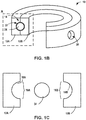
- FIG. 1B is a conceptual and schematic diagram illustrating a partial view of an example system including the assembly of FIG. 1A .
- Assembly 10 may be assembled as shown in FIG. 1B , with mechanical interlock 14 disposed in a joint region 22 defined by joint surfaces 18A and 18B of joining regions 16A and 16B. While a single joint region 22 is shown in the example assembly of FIG. 1B , in other examples, components 12A and 12B may define a plurality of respective joint regions, and a solid retainer material may be introduced into respective joint regions of the plurality of joint regions to form mechanical interlock 14. In some examples, different compositions of the solid retainer material may be introduced into different joint regions, or in different portions of the same joint region.
- Mechanical interlock 14 may include a solid retainer material.
- the solid retainer material may include any solid material, such as a module or powder, that may form mechanical interlock 14 as discussed herein.
- the solid retainer material may be selected to provide sufficient strength and rigidity to mechanical interlock 14 to secure first component 12A to second component 12B or restrain first component 12A relative to second component 12B.
- Mechanical interlock 14 may be formed from any suitable metal, alloy, or ceramic for the particular joint conditions.
- the solid retainer material is a superalloy having a high mechanical strength.
- mechanical interlock 14 may experience high sheer forces created between component 12A and component 12B, such that a superalloy having a high sheer strength at elevated temperatures may be used to ensure sufficient strength to join components 12A and 12B.
- Example superalloys that may be used may include, but are not limited to, Ni-based superalloys, Co-based superalloys, Fe-based superalloys, and the like.
- the solid retainer material may have a sheer strength greater than about 20,000 pounds per square inch (psi) at room temperature, such as greater than about 50,000 psi.
- MarM Ni-based superalloy has a shear strength at room temperature of about 64,000 psi and a shear strength at 900 F of about 62,000 psi.
- the solid retainer material includes a metal or alloy that melts at a temperature of greater than about 1315 °C (about 2400 °F).
- the solid retainer material may include a metal or alloy substantially similar to or substantially the same as (e.g., the same or nearly the same) the alloy in first component 12A, second component 12B, or both.
- the solid retainer material is a ceramic-based material having high stability at high temperatures.
- mechanical interlock 14 may experience high temperatures in a gas turbine engine environment, such that a ceramic-based material having high stability may be used to ensure sufficient strength at high temperatures to join component 12A and 12B.
- Example ceramic-based materials that may be used include, but are not limited to, transition metal borides, carbides, nitrides, oxides, and the like.
- mechanical interlock 14 includes a plurality of solid retainer modules 24.
- Each solid retainer module 24 may be configured to fit through opening 20 into joint region 22 and, individually as solid retainer module 24 or collectively as the plurality of solid retainer modules 24, secure or restrain first component 12A to second component 12B.
- each of the plurality of solid retainer modules 24 may have a predetermined shape.
- the predetermined shape may correspond to a portion, such as one or both of joint surfaces 18A or 18B, of a shape of joint region 22.
- joint region 22 may include a relatively simple geometry as shown in FIG.
- solid retainer modules 24 may be cut, machined, or formed into a relatively simple shape, or a more complex, e.g., including curvature, angles, apertures, or the like to form mechanical interlock 14.
- solid retainer modules 24 may include a substantially two-dimensional shape (e.g., a plane) or a three-dimensional shape (e.g., including curvature, planes at angles with respect to one another, and the like).
- the plurality of solid retainer modules 24 may have a variety of sizes and shapes.
- each solid retainer module 24 may be sized to permit placement of the solid retainer module 24 in joint region 22 with a small clearance to permit movement of each solid retainer module 24 through joint region 22.
- dimensions of a geometry e.g., a diameter, length, width, height, etc.
- dimensions of a geometry of joint region 22 may be slightly smaller than dimensions of a geometry of joint region 22, such that the plurality of solid retainer modules 24 may be inserted through opening 20 (or multiple openings) and positioned in joint region 22.
- the plurality of solid retainer modules 24 may have a diameter greater than about one millimeter and/or less than about 95% of a diameter of joint region 22, such as about 2.5 millimeters. In some instances, a diameter of the plurality of solid retainer modules 24 may be dependent on a geometry of joint region 22. For example, a smallest dimension of joint region 22 may restrict a size of the plurality of retainer modules, such that nonuniformities of joint region 22 or an asymmetrical shape of the plurality of solid retainer modules 24 may limit an ability of the plurality of solid retainer modules 24 to move within joint region 22. While shown as a same size, in some instances, the plurality of solid retainer modules may include two or more different sizes.
- a first plurality of solid retainer modules may have a first size corresponding to a dimension of joint region 22, while a second plurality of solid retainer modules may have a second size corresponding to gaps between adjacent solid retainer modules of the first plurality of solid retainer modules, such that a volume of joint region 22 may be include large solid retainer modules while being more fully filled with solid retainer material than large solid retainer modules alone.
- Shapes that may be used for solid retainer modules 24 may include, but are not limited to, spheres, cylinders, barrel-shapes, ovular spheres, blocks, cones, and the like. Various shapes and sizes of solid retainer modules 24 may be discussed further in FIGS. 3A-3C below.
- the solid retainer material of mechanical interlock 14 is not bulk heated above a melting temperature of the solid retainer material to form mechanical interlock 14.
- the solid retainer material of mechanical interlock 14 does not melt during formation of mechanical interlock 14.
- mechanical interlock 14 may include a solid retainer material that has substantially the same microstructure as the solid retainer material prior to insertion into joint region 22.
- FIG. 1C is a conceptual and schematic diagram illustrating a partial sectional and exploded view of region A of the system of FIG. 1B .
- a joint surface may be defined by joint region 22, for example, a surface of one or both of first or second joining regions 16A or 16B.
- Mechanical interlock 14 secures first component 12A to second component 12B or restrains first component 12A relative to second component 12B.
- the shape and geometry of mechanical interlock 14 (for example, substantially conforming to a portion or dimension of joint region 22, such as joint surfaces 18A and/or 18B) may mechanically lock or secure a portion of first component 12A relative to a respective portion of second component 12B.
- first component 12A and second component 12B may be limited in movement in at least one direction.
- the plurality of solid retainer modules 24 may at least partially surround at least one of first component 12A or second component 12B.
- mechanical interlock 14 may surround a perimeter subtending an angle greater than 180°, or greater than 210°, or greater than 240°, or greater than 270°, or greater than 300°, or substantially 360° (for example, within 1°, 5°, or 10° of 360°) about a central axis defined respectively by first component 12A or second component 12B.
- mechanical interlock 14 may form a segmented ring, or a segmented sleeve, surrounding one or both of components 12A or 12B.
- the mechanical interlock may be exterior to an exterior surface defined by one of components 12A or 12B, and interior to an interior surface defined by the other of components 12A or 12B.
- the solid retainer material and mechanical interlock 14 formed from the solid retainer material
- any suitable configuration of mechanical interlock 14 relative to components 12A and 12B that secures components 12A and 12B together may be used.
- Mechanical interlock 14 ultimately formed from the plurality of solid retainer modules 24 may possess sufficient mechanical strength and high temperature oxidation resistance to be utilized in a high temperature mechanical system, such as a nozzle guide vane in a gas turbine engine.
- a composite mechanical interlock securing two or more components may be formed a solid retainer material and one or more binder materials without melting the solid retainer material.
- FIG. 2A is a conceptual and schematic diagram illustrating an exploded view of an example assembly 30 for joining a first component 32A and a second component 32B by inserting a solid retainer material and a binder to form a composite mechanical interlock 34.
- first component 32A, second component 32B, a first joining region 36A, a second joining region 36B, a first joint surface 38A, a second joint surface 38B, and a opening 40 may correspond to first component 12A, second component 12B, first joining region 16A, second joining region 16B, first joint surface 18A, second joint surface 18B, and opening 20 of FIGS. 1A-1C .
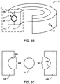
- FIG. 2B is a conceptual and schematic diagram illustrating a partial view of an example system including the assembly of FIG. 2A .
- Composite mechanical interlock 34 includes a plurality of solid retainer modules 44 and a binder 46.
- the plurality of solid retainer modules 44 may correspond to (e.g., have similar compositions, microstructural properties, and/or macrostructural properties as) the solid retainer modules 24 of FIGS. 1A-1C .
- Composite mechanical interlock 34 may have a shape that at least partially conforms to joint region 42.
- Binder 46 may include one or more of a putty or a paste.
- binder 46 includes a braze material.
- the braze material may include a Ni-based or Co-based wide gap braze alloy.
- the braze material may include greater amounts of alloying elements that some other braze materials used in braze foils, which may contribute to improved mechanical properties, chemical properties, or both compared to some other braze materials used in braze foils.
- the braze material may possess sufficient mechanical strength and high temperature oxidation resistance to be used in a nozzle guide vane in a gas turbine engine.
- the braze material may include both a braze alloy powder (a low-melt powder composition) and a superalloy powder (a high-melt powder composition).
- the low-melt alloy powder composition is an alloy, or a mixture of alloys, that substantially melts below a braze or joining temperature (hence the name "low-melt” or "braze powder”).
- the high-melt alloy powder composition is an alloy, or a mixture of alloys, that remains substantially unmelted at the braze temperature, because the composition has a melting temperature above the braze temperature (hence the name "high-melt” or "superalloy powder").
- the braze alloy powder and the superalloy powder may have specific powder mesh sizes, and may be produced by induction melting the braze alloy or the superalloy powder, respectively, in vacuum or an argon atmosphere, followed by argon gas atomization. Each individual powder component used in the braze material may be analyzed to confirm the particle size and chemical compositions.
- the low-melt powder composition includes an alloy or a mixture of alloys that melt at a temperature below about 1260 °C (about 2300 °F). In some examples the low-melt alloy powder comprises a mixture of two or more low-melt alloys.
- the high-melt alloy powder composition may include a single high-melt alloy or a mixture of alloys that melts at a temperature of greater than about 1315 °C (about 2400 °F). In some examples, the high-melt powder composition may include an alloy or mixture of alloys with a chemistry that is the similar to or substantially the same (e.g., the same or nearly the same) as the alloy in first component 12A, second component 12B, or both.
- the low-melt powder composition and the high-melt powder composition may be combined in any selected ratio.
- the braze material may include a powder mixture consisting of between about 20 wt. % and about 80 wt. % low-melt powder composition and a balance high-melt powder composition (a ratio of between about 1:4 and about 4:1 low-melt powder : high-melt powder).
- braze alloy powder may be a mixture of more than one braze alloy, which are all powder.
- higher weight percentages of high-melt powder may provide better mechanical properties in view of their reduced levels of boron, silicon, or both.
- higher percentages of low-melt powders may provide improved braze flow.
- a proper balance between mechanical properties and braze flow should be selected, for example, to promote flow of the braze material to ultimately at least partially conform to joint region 42, while yet retaining sufficient strength or rigidity to mechanically secure components 32A and 32B relative to each other.
- the at least softened material may flow, migrate, or otherwise at least partially occupy joint region 42, and on cooling, form a mechanical interlock in joint region 42.
- the braze material can be introduced into joint region 42 with the plurality of solid retainer modules 44 with the ability to change shape or "morph" when heated from a pliable or ductile green state into a state that further softens and has the ability to substantially conform to the shape of joint region 42 or a cavity or channel in which the braze material is placed and the plurality of solid retainer modules 44.
- Such deforming of the braze material may be accomplished at a temperature well below the melting point of components 32A or 32B, for example, without the braze material itself melting into a full liquid state (in contrast with bi-casting, which may require a liquid molten state).
- the braze material may be molten or heated to a liquid state
- the plurality of solid retainer modules 44 and components 32A or 32B themselves may be maintained in a solid state, retaining the integrity of the plurality of solid retainer modules 44 and components 32A and 32B.
- the braze material may be formed into multiple sections placed adjacent to each other in joint region 22. In such a configuration, the multiple sections will securely bond and fuse to each other during a high temperature furnace operation.
- the melting characteristics of the braze material may change in response to high temperature exposure.
- the braze material may include a relatively small percentage of a low melting component, for example, brazing powder, and a relatively higher percentage of a high melting component, for example, superalloy.
- the low melting component may include an alloy additive that depresses the melting point of the low melting component, causing the low melting component to liquefy at this lower temperature, causing the braze material to soften and slip (and unite if more than one strip is used) during the furnace operation.
- the alloy addition that depresses the melting point of the low melting component may diffuse during the furnace operation (or during a post-furnace diffusion heat treatment) into the larger volume of high melting component, for example, superalloy.
- Such diffusion may raise the re-melt temperature of the mechanical interlock ultimately formed from the braze material, such that composite mechanical interlock 34 (morphed and fused) formed from the braze material transforms into a rigid metallic structure, (for example a "ring") after the furnace operation and when in subsequent use at high temperature operating conditions.
- the braze material may transform into an integrally shaped and consolidated mechanical interlock (in some examples, a "ring") trapped in cavities or channels bridging between components 32A and 32B.
- the mechanical interlock formed from the braze material may thus function as a high strength, high temperature capable (closely conforming) structural member with material properties similar to a high temperature superalloy, for example, superalloy constituent(s) used in the formulation of the braze material.
- FIG. 2C is a conceptual and schematic diagram illustrating a partial sectional and exploded view of region A of the system of FIG. 2B .
- first joint surface 38A or second joint surface 38B may include an adhesion resistant coating.
- the adhesion resistant coating may resist adherence or metallurgical bonding of the mechanical interlock formed from the brazing material to surfaces of joint region 42.
- a joint surface defined by joint region 42 for example, a surface of one or both of first or second joining regions 36A or 36B, may be coated with an adhesion resistant coating.
- one or both of joint surfaces 38A or 38B of joint region 42 may be respectively coated with the adhesion resistant coating.
- At least a portion of the adhesion resistant coating may act as a leave-in-place "stop-off, substantially preventing the braze material (or the at least softened material formed by heating the braze material, or the composite mechanical interlock 34 formed by cooling the at least softened material) from adhering to surfaces defined by joint region 42, for example, joint surfaces 38A and 38B.
- the adhesion resistant coating present before, during, and after forming mechanical interlock 34 avoids or substantially prevents introducing a gap (as contrasted with a stop-off removed after application).
- the adhesion resistant coating may result in a line-on-line fit or connection between components 32A and 32B and composite mechanical interlock 34 ultimately formed from the braze material and the plurality of solid retainer modules 44, without allowing the braze material to form a metallurgical bond or braze joint with components 32A and 32B.
- a monolithic mechanical interlock securing two or more components may be formed from a sintered solid retainer material without melting the solid retainer material.
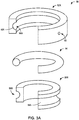
- FIG. 3A is a conceptual and schematic diagram illustrating an exploded view of an example assembly 50 for joining a first component 52A and a second component 52B by inserting a solid retainer material and a binder into a joint region 62 to form a monolithic mechanical interlock 54.
- first component 52A, second component 52B, a first joining region 56A, a second joining region 56B, a first joint surface 58A, a second joint surface 58B, and joint region 62 may correspond to first component 12A, second component 12B, first joining region 16A, second joining region 16B, first joint surface 18A, second joint surface 18B, and joint region 22 of FIGS. 1A-1C .
- first component 52A includes an opening 60 that is smaller than opening 20 of FIG. 1A .
- mechanical interlock 54 may be formed from solid retainer particles using injection molding, as will be described further below.
- opening 60 may have a smaller size than opening 20 of FIG. 1A , as opening 60 does not have to accommodate the relatively larger solid retainer modules of the plurality of solid retainer modules 24.
- FIG. 3B is a conceptual and schematic diagram illustrating a partial view of an example system including the assembly of FIG. 3A .
- Monolithic mechanical interlock 54 may be an injection molded mechanical interlock that includes a sintered solid retainer material 64.
- Monolithic mechanical interlock 54 may have a shape that at least partially conforms to joint region 62.
- the sintered solid retainer material 64 may correspond to (e.g., have similar compositions and/or microstructural properties as) the solid retainer modules 24 of FIGS. 1A-1C .
- the sintered solid retainer material 64 may be formed from solid retainer powder, as will be described further in FIGS. 4D and 5C below.
- FIG. 3C is a conceptual and schematic diagram illustrating a partial sectional and exploded view of region A of the system of FIG. 3B .
- a diameter of sintered solid retainer material 64 may be substantially the same as a diameter of joint region 62, while in other examples, sintered solid retainer material 64 may be smaller than a diameter of joint region 62, such as in examples in which sintering of a solid retainer material preform formed by debinded solid retainer powder shrinks in one or more dimensions to form a denser sintered solid retainer material 64 having a reduced size in at least one dimension.
- mechanical interlocks discussed herein may be formed from a plurality of solid retainer modules having relatively simple geometries.
- a joint region for various components may have a relatively standard, consistent, and/or symmetrical size, such that a plurality of solid retainer modules having a relatively standard or uniform size or shape may be used to form the mechanical interlock.
- FIG. 4A is a conceptual and schematic diagram illustrating a cross-sectional top view of an example assembly 70 for joining a first component 72A and a second component 72B by inserting generically shaped solid retainer modules 76 into a joint region 74 to form a mechanical interlock. As illustrated in FIG.
- each solid retainer module 76 of the plurality of solid retainer modules 76 has a spherical shape with a diameter slightly smaller than a dimension of joint region 74 between first component 72A and second component 72B.
- Such simple geometries of the plurality of solid retainer modules 76 may fit a wide variety of joint region shapes.
- mechanical interlocks discussed herein may be formed from relatively complex geometries.
- a joint region may have a relative complex, unique, and/or asymmetrical shape, such that a plurality of solid retainer modules having a relatively unique shape may be used to form the mechanical interlock.
- FIG. 4B is a conceptual and schematic diagram illustrating a cross-sectional top view of an example assembly 80 for joining a first component 82A and a second component 82B by inserting specifically shaped solid retainer modules 86 into a joint region 84 to form a mechanical interlock. As illustrated in FIG.
- each solid retainer module 86 of the plurality of solid retainer modules 86 has a domed cylindrical shape with a diameter slightly smaller than a dimension of joint region 84 between first component 82A and second component 82B.
- the cylindrical shape of each solid retainer module 86 may increase a volume of solid retainer material in joint region 84 as compared to, for example, a spherical shape, while the domed shape of each solid retainer module 86 may enable the solid retainer module 86 to advance more easily through joint region 84 as compared to, for example, a strictly cylindrical shape.
- Such complex geometries of the plurality of solid retainer modules 86, alone or in combination with a shape of joint region 84, may provide enhanced strength compared to shapes of solid retainer modules that are not as specific to a shape of the joint region.
- mechanical interlocks discussed herein may be composite mechanical interlocks formed from relatively large solid retainer modules and a binder.
- a joint region for components may form an interface between two environments.
- a plurality of solid retainer modules while providing sufficient strength between the components, may permit air to pass through the joint region between the two environments.
- the composite mechanical interlock may seal the two environments and/or provide additional support or strength to the composite mechanical interlock.
- FIG. 4C is a conceptual and schematic diagram illustrating a cross-sectional top view of an example assembly 90 for joining a first component 92A and a second component 92B by inserting a plurality of solid retainer modules 96 and a binder 98 into a joint region 94 to form a composite mechanical interlock.
- FIG. 4C may illustrate a mechanical interlock prior to curing binder 98.
- each solid retainer module 96 of the plurality of solid retainer modules 96 is at least partially surrounded by binder 98.
- Binder 98 contacts the plurality of solid retainer modules 96 and, at least prior to solidifying binder 98, one or more surfaces of components 92A and 92B corresponding to joint region 94.
- binder 98 and the plurality of solid retainer modules 96 may form the composite mechanical interlock, such as composite mechanical interlock 34 of FIGS. 2A-2C .
- Such composite mechanical interlocks may provide a seal to joint region 94, as binder 98 may fill in voids that previously provided a path for fluids to pass between components 92.
- mechanical interlocks discussed herein may be monolithic mechanical interlocks formed from relatively small (e.g., powders) solid retainer particles and a binder.
- solid retainer powders may have advantageous properties, such as high strength, that may be integrated into a mechanical interlock without exposing the solid retainer powders to high temperatures associated with a melting point of the solid retainer powders.
- FIG. 4D is a conceptual and schematic diagram illustrating a cross-sectional top view of an example assembly 100 for joining a first component 102A and a second component 102B by inserting binder 108 having solid retainer particles 106 into a joint region 104 to form a mechanical interlock.
- 4D may illustrate joint region 104 prior to debinding binder 108 and sintering solid retainer particles 106, such that the mechanical interlock is not yet formed.
- solid retainer particles 106 are surrounded by binder 108 and distributed throughout the joint region.
- the solid retainer particles 106 may form a monolithic mechanical interlock that includes solid retainer material distributed throughout joint region 104.
- the solid retainer particles 106 may form a continuous phase through joint region 104.
- Solid retainer particles 106 may have a variety of shapes including, but not limited to, spheres, random-shapes, blocks, and the like. Solid retainer particles 106 may have a variety of sizes including, but not limited to, about 1 micrometer to about 1 millimeter, such as about 10 micrometers to about 100 micrometers. Solid retainer particles 106 may have a variety of distributions (e.g., a ratio between solid particles 106 to binder 108) including, but not limited to, about 4:1 to about 20:1. For example, the distribution of solid retainer particles 106 may be related to a desired viscosity and/or stability of solid retainer particles 106 and binder 108. In some examples, solid retainer particles 106 may have a composition similar to the plurality of solid retainer modules 24 and 44 discussed in FIGS. 1B and 1C and FIGS. 2B and 2C , respectively.
- Binder 108 may be selected to hold solid retainer particles 106 together and/or provide solid retainer particles 106 with fluidity, such that solid retainer particles 106 may be relatively evenly distributed in the joint region.
- Binder 108 may include a filler and a structural polymer.
- metal or ceramic injection binders 108 may be used including, but not limited to: polymer-based binders, such as polyacetal, polyamide, or methyl cellulose fillers and polyethylene, polybutene, poly(ethylene-co-vinyl acetate), polystyrene, poly(methyl methacrylate), poly(ethylene glycol), or poly(vinyl acetate) structural polymers; wax-based binders, such as paraffin-based wax, microcrystalline wax, synthetic hydrocarbon wax, or oxidized polyethylene wax fillers and polyethylene, polybutene, poly(ethylene-co-vinyl acetate), polystyrene, poly(methyl methacrylate), poly(ethylene glycol), or poly(vinyl acetate) structural polymers; combinations of waxes and polymers, and the like.
- polymer-based binders such as polyacetal, polyamide, or methyl cellulose fillers and polyethylene
- polybutene poly(ethylene-co-vinyl acetate), polysty
- binder 108 may be selected to be a powder at ambient temperature and a liquid at relatively low processing temperatures, such as temperatures lower than a melting point of solid retainer particles 106.
- binder 108 may include additives, such as dispersants (e.g., to increase wettability of solid retainer particles 106), stabilizers (e.g., to reduce agglomeration of solid retainer particles 106), plasticizers (e.g., to increase flow of solid retainer particles 106 and/or binder 108), lubricants (e.g., to reduce interaction between solid retainer particles 106 and binder 108), and the like.
- FIG. 5A is a flow diagram illustrating an example technique for forming a mechanical interlock using a solid retainer material to join components.
- the technique of FIG. 5A will be described with reference to assembly 10 of FIGS. 1A-1C for purposes of illustration only. It will be appreciated that the technique of FIG. 5A may be performed with a different assembly or system, or that assembly 10 may be used in a different joining technique.
- the technique of FIG. 5A may optionally include forming opening 20 and/or joint surfaces 18A and 18B of first component 12A and second component 12B, respectively (110).
- the geometry of joint region 22 may depend on the type of joint defined by joint surfaces 18A and 18B and may include, for example, a bridle j oint, a butt j oint, a scarf j oint, a miter join, a dado j oint, a groove joint, a tongue and groove j oint, a mortise and tenon j oint, a birdsmouth j oint, a halved j oint, a biscuit j oint, a lap j oint, a double lap j oint, a dovetail j oint, or a splice joint.
- joint surfaces 18A and 18B of components 12A and 12B may be inspected and cleaned, for example, before the positioning (112).
- the cleaned joint surfaces 18A and 18B may produce a more uniform joint than uncleaned joint surfaces.
- the technique of FIG. 5A includes positioning components 12A and 12B to define joint region 22 (112).
- components 12A and 12B may be positioned so that joining regions 16A and 16B are near each other.
- the technique of FIG. 5A also includes inserting a solid retainer material into joint region 22 through opening 20 to form mechanical interlock 14 (114).
- the solid retainer material may include a plurality of solid retainer modules 24.
- the plurality of solid retainer modules 24 may be inserted in joint region 22 such that the plurality of solid retainer modules 24 form mechanical interlock 14 between first component 12A and second component 12B.
- the technique of FIG. 5A includes sealing opening 20 to retain the plurality of solid retainer modules 24 within joint region 22 (116). For example, opening 20 may be brazed or welded to prevent the plurality of solid retainer modules 24 from passing through opening 20.
- FIG. 5A may be used to form mechanical interlock 14 between components 12A and 12B from the plurality of solid retainer modules 24 in assembly 10 of FIGS. 1A-1C , without melting the mechanical retainer material.
- FIG. 1A illustrates a simplified conceptual and schematic view of an example first component 12A, an example second component 12B, and an example mechanical interlock 14, in other examples, example assemblies may include components and a mechanical interlock defining a more complication geometry.
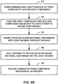
- FIG. 5B is a flow diagram illustrating an example technique for forming a composite mechanical interlock using a solid retainer material to join components.
- the technique of FIG. 5B will be described with reference to assembly 30 of FIGS. 2A-2C for purposes of illustration only. It will be appreciated that the technique of FIG. 5B may be performed with a different assembly or system, or that assembly 30 may be used in a different joining technique.
- the technique of FIG. 5B may optionally include forming opening 40 and/or joint surfaces 38A and 38B of first component 32A and second component 32B, respectively (120), and positioning components 32A and 32B to define joint region 42 (122).
- the example technique of FIG. 5B includes optionally coating a joint surface of joint region 42 defined by first and second components 32A and 32B with an adhesion resistant coating (not shown).
- the coating technique may include physical vapor deposition, chemical vapor deposition, plasma deposition, spraying, deposition of a liquid, marker, or putty, atmospheric exposure at high temperatures, or any other suitable coating technique.
- the example technique may not include the coating step, and instead, pre-coated components 32A and 32B may be used.
- the technique of FIG. 5B includes inserting a solid retainer material, such as the plurality of solid retainer modules 44, and binder 46 into joint region 42 through opening 40 (124).
- Binder 46 may be disposed in joint region 42 such that binder 46 contacts respective joint surfaces of joint region 42, for example, joint surfaces 38A and 38B.
- a clamp, press, or other mechanism may be used to compress the braze material between joining regions 36A and 36B to cause intimate contact between joint surfaces 38A and 38B and surfaces of binder 46 and, correspondingly, composite mechanical interlock 34, although intimate contact between joint surfaces 38A and 38B and surfaces of composite mechanical interlock 34 is not required.
- the technique of FIG. 5A includes sealing opening 20 to retain the plurality of solid retainer modules 24 within joint region 22 (126).
- the technique of FIG. 5B includes solidifying binder 46 around the plurality of solid retainer modules 44 to form composite mechanical interlock 34 (128).
- binder 46 is a braze material
- the braze material may be melted and solidified around the plurality of solid retainer modules 44 to form composite mechanical interlock 34.
- FIG. 2 may be used to form a mechanical interlock between components 32A and 32B from the plurality of solid retainer modules 44 and binder 46 in assembly 10 of FIGS. 2A-2C , without melting the mechanical retainer material.
- FIGS 2A-2C illustrate a simplified conceptual and schematic view of an example first component 32A, an example second component 32B, and an example composite mechanical interlock 34
- example assemblies may include components and a mechanical interlock defining a more complicated geometry.
- FIG. 5C is a flow diagram illustrating an example technique for joining components including inserting a solid material.
- the technique of FIG. 5C will be described with reference to assembly 50 of FIGS. 3A-3C and assembly 100 of FIG. 4D for purposes of illustration only. It will be appreciated that the technique of FIG. 5C may be performed with a different assembly or system, or that assembly 50 or assembly 100 may be used in a different joining technique.
- the technique of FIG. 5C may optionally include forming opening 60 and/or joint surfaces 58A and 58B of first component 52A and second component 52B, respectively (130), and positioning components 52A and 52B to define joint region 62 (132).
- the technique of FIG. 5C includes inserting a solid retainer powder (e.g., solid retainer particles 106) and a binder (e.g., binder 108) into joint region 104 through an opening (134).
- a solid retainer powder e.g., solid retainer particles 106
- a binder e.g., binder 108
- solid retainer particles 106 may be dispersed in binder 108, such that the mixture of solid retainer particles 106 and binder 108 may be injected through an opening into joint region 104.
- the mixture of solid retainer particles 106 and binder 108 may be injected using any suitable metal injection molding and/or ceramic injection molding techniques.
- binder 108 may be heated prior or subsequent to injection of solid retainer particles 106 and binder 108 to flow solid retainer particles 106 and binder 108 through the joint region.
- debinding may involve any of thermal debinding (e.g., heating binder 108 to decompose binder 108 and remove binder 108 using gases), solvent debinding (e.g., contacting binder 108 with a solvent to dissolve binder 108 and remove the dissolved binder 108), and/or catalytic debinding (e.g., contacting binder 108 with a gaseous catalyst to decompose binder 108 and remove binder 108 using gases).
- thermal debinding e.g., heating binder 108 to decompose binder 108 and remove binder 108 using gases
- solvent debinding e.g., contacting binder 108 with a solvent to dissolve binder 108 and remove the dissolved binder 108
- catalytic debinding e.g., contacting binder 108 with a gaseous catalyst to decompose binder 108 and remove binder 108 using gases.
- the technique of FIG. 5C include sintering the solid retainer material preform to form monolithic mechanical interlock 54 (138).
- assembly 100 may be placed into a furnace and heated to a sintering temperature configured to joint solid retainer particles 106 to form monolithic mechanical interlock 54 of FIGS. 3A-3C .
- the sintering temperature of solid retainer particles 106 may be lower than a melting temperature of solid retainer particles 106.
- the technique of FIG. 5C includes sealing opening 60 (140). While sealing the opening is illustrated as being performed after the solid retainer particles are sintered, in some instances, the opening may be sealed prior to solid retainer particles 106 being sintered, such as after binder 108 has been removed.
- the subject matter of the disclosure may also relate, among others, to the following aspects:
Landscapes
- Engineering & Computer Science (AREA)
- Mechanical Engineering (AREA)
- Chemical & Material Sciences (AREA)
- Composite Materials (AREA)
- Manufacturing & Machinery (AREA)
- Materials Engineering (AREA)
- Ceramic Products (AREA)
- Pressure Welding/Diffusion-Bonding (AREA)
- Powder Metallurgy (AREA)
Abstract
Description
- The present disclosure generally relates to techniques and assemblies for joining components.
- Casting may be used to form metal or alloy components. However, casting relatively large articles or articles having a relatively complex geometry in a single operation may result in deviation of the cast article from specifications or tolerance. Instead of casting or otherwise forming large or complex articles as a single piece or component, such articles may be cast or otherwise fabricated in the form of separate components, which may be joined to form an assembly. For example, the separate components may be arranged at specific relative positions and bonded through thermal processes, such as welding, to form the assembly.
- The present disclosure provides a method and an assembly as set out in the appended claims.
- The disclosure describes example assemblies and techniques for joining a first component to a second component at a low temperature using a solid retainer material that forms a mechanical interlock.
- In some examples, the disclosure describes an example technique including positioning a first component and a second component adjacent to each other to define a joint region between adjacent portions of the first component and the second components. The example technique further includes inserting a solid retainer material into the joint region through an opening in one of the first component or the second component to form a mechanical interlock between the first component and the second component. The solid retainer material includes at least one of a metal, a metal alloy, or a ceramic. The example technique includes sealing the opening to retain the solid retainer material within the joint region. In some examples, the solid retainer material includes a plurality of solid retainer modules. In some examples, the example technique includes inserting a binder into the joint region through the opening and solidifying the binder to form a composite mechanical interlock between the first component and the second component.
- In some examples, the disclosure describes an example assembly including a first component, a second component, and a mechanical interlock. The first and second components are positioned adjacent to each other to define a joint region between adjacent portions of the first component and the second component. The mechanical interlock includes a solid retainer material disposed in the joint region. The solid retainer material includes at least one of a metal, a metal alloy, or a ceramic. In some examples, the solid retainer material includes a plurality of solid retainer modules. In some examples, the mechanical interlock includes a binder around the solid retainer material to form a composite mechanical interlock.
- The details of one or more examples are set forth in the accompanying drawings and the description below. Other features, objects, and advantages will be apparent from the description and drawings, and from the claims.
- The skilled person will appreciate that except where mutually exclusive, a feature or parameter described in relation to any one of the above aspects may be applied to any other aspect. Furthermore, except where mutually exclusive, any feature or parameter described herein may be applied to any aspect and/or combined with any other feature or parameter described herein.
- Embodiments will now be described by way of example only, with reference to the Figures, in which:
-
FIG. 1A is a conceptual and schematic diagram illustrating an exploded view of an example assembly for joining a first component and a second component by using a plurality of solid retainer modules to form a mechanical interlock. -
FIG. 1B is a conceptual and schematic diagram illustrating a partial view of an example system including the assembly ofFIG. 1A . -
FIG. 1C is a conceptual and schematic diagram illustrating a partial sectional and exploded view of region A of the system ofFIG. 1B . -
FIG. 2A is a conceptual and schematic diagram illustrating an exploded view of an example assembly for joining a first component and a second component by using a plurality of solid retainer modules and a binder to form a composite mechanical interlock. -
FIG. 2B is a conceptual and schematic diagram illustrating a partial view of an example system including the assembly ofFIG. 2A . -
FIG. 2C is a conceptual and schematic diagram illustrating a partial sectional and exploded view of region A of the system ofFIG. 2B . -
FIG. 3A is a conceptual and schematic diagram illustrating an exploded view of an example assembly for joining a first component and a second component by using a sintered solid retainer material to form a composite mechanical interlock. -
FIG. 3B is a conceptual and schematic diagram illustrating a partial view of an example system including the assembly ofFIG. 3A . -
FIG. 3C is a conceptual and schematic diagram illustrating a partial sectional and exploded view of region A of the system ofFIG. 3B . -
FIG. 4A is a conceptual and schematic diagram illustrating a cross-sectional top view of an example assembly for joining a first component and a second component by inserting generically shaped solid retainer modules to form a mechanical interlock. -
FIG. 4B is a conceptual and schematic diagram illustrating a cross-sectional top view of an example assembly for joining a first component and a second component by inserting specifically shaped solid retainer modules to form a mechanical interlock. -
FIG. 4C is a conceptual and schematic diagram illustrating a cross-sectional top view of an example assembly for joining a first component and a second component by inserting solid retainer modules and a binder to form a mechanical interlock. -
FIG. 4D is a conceptual and schematic diagram illustrating a cross-sectional top view of an example assembly for joining a first component and a second component by inserting injection mold having solid particles to form a mechanical interlock. -
FIG. 5A is a flow diagram illustrating an example technique for forming a mechanical interlock using solid retainer modules to join components. -
FIG. 5B is a flow diagram illustrating an example technique for forming a composite mechanical interlock using solid retainer modules and a binder to join components. -
FIG. 5C is a flow diagram illustrating an example technique for forming a monolithic mechanical interlock using a sintered solid retainer material to join components. - The disclosure describes example assemblies and techniques for joining a first component to a second component at a low temperature using a solid retainer material that forms a mechanical interlock. A mechanical interlock may be an interlock that has a mechanism that is primarily mechanical (e.g., not adhesive or chemical). A solid retainer material may be a retainer material that does not undergo a bulk melting process (e.g., a thermal process in which a bulk of the retainer material is raised to or above a melting temperature) after insertion of the retainer material into the joint region. The first component and the second component define a joint region, such as adj acent channels or other inset structures. The solid retainer material is inserted and sealed into the joint region as either a preformed structure or subsequently formed structure to form a mechanical interlock in the joint region, thereby restraining the first component relative to the second component. For example, the mechanical interlock may extend at least partially into a channel of each of the first and second components, such that the first component and the second component at least partially surround the mechanical interlock. The first or second components may include components benefitting from a close fitting (relatively low leakage) structural connection in high-temperature operating conditions, such as components of a gas turbine engine, for example, a high-pressure nozzle guide vane and shroud.
- While techniques such as bi-casting may be used to produce an integrally formed metallic joint to structurally connect components, bi-casting may require a casting foundry including, for example, separate furnace preheat and liquid metal pouring operations with elaborate tooling, as well as close monitor and control during various stages of the process. To integrally form a bi-cast joint, a molten metal or alloy may be heated to a temperature at or above the melting point of components being joined. Moreover, any significant leakage of molten metal or alloy during the bi-casting process may affect the integrity of components being joined or of surrounding furnace tooling, which may be costly and difficult to replace. As an alternative to joining bi-cast components using the metal or alloy of the components, a different metal may be melted and flowed between the components to join the components. This molten metal may have a lower melting point than the components to be joined, but may still expose the components to high temperatures that may cause microstructural changes in the components. Additionally, the molten metal may have less advantageous mechanical properties, such as sheer strength, than metals or alloys having higher melting point temperatures. Regardless of whether a same or different molten metal or alloy is used to join the components, such molten metal or alloy may be difficult to apply and may require large equipment that may be expensive or difficult to position at a particular location, requiring disassembly of the components from a corresponding machine prior to joining the components.
- In contrast, example techniques and assemblies according to the disclosure may incorporate high strength materials using lower temperatures that are below the melting temperatures of the high strength materials. For example, the solid retainer material forming the mechanical interlock may be a material, such as a superalloy or a ceramic, that has a higher strength than a material that has been melted and solidified within a joint region to form a mechanical interlock. As another example, both a mechanical interlock formed from the solid retainer material and the components that are secured by the mechanical interlock may be exposed to lower temperatures than a mechanical interlock formed by melting and solidifying the retainer material in the joint region. As another example, the solid retainer material may form a composite mechanical interlock with other materials, such as braze materials, that may melt and solidify around the solid retainer material to seal a joint while providing better mechanical properties, such as higher sheer strength, than the solidified braze materials alone.
- In some instances, example techniques and assemblies according to the disclosure may form a mechanical interlock that incorporates preformed structures. For example, the retainer material may be formed into solid retainer modules having microstructural properties that may remain substantially unchanged between formation of the solid retainer modules and incorporation into a joint region as a mechanical interlock. As another example, the solid retainer modules may include various macrostructural properties, such as shape and size, that may not be achieved with a monolithic mechanical interlock formed in the joint region, such as through melting a retainer material or incorporating a retainer powder in a melted carrier material.
- In some instances, example techniques and assemblies according to the disclosure may form a mechanical interlock without the use of any molten metals or alloys. For example, the solid retainer material may form a mechanical interlock in the joint region without melting the solid retainer material, thus eliminating large and/or power intensive equipment for melting metals or alloys prior to insertion into the joint region or while contained in the joint region. As a result, components may be secured less expensively, in the field, and/or without requiring disassembly of the components prior to forming a joint between the components.
- In some examples, a mechanical interlock securing two or more components may be formed from a solid retainer material without exposing the components to molten metals, alloys, or ceramics.
FIG. 1A is a conceptual and schematic diagram illustrating an exploded view of anexample assembly 10 for joining afirst component 12A and asecond component 12B by inserting and securing a solid retainer material in a joint region to form amechanical interlock 14. In some examples, first andsecond components components components - Each of
components components components FIG. 1A illustratescomponents second components components 12B may be a vane having multiple different curvatures. - In some examples, one or both of
components second components components components components - In some examples, one or both of
components -
First component 12A defines at least one joiningregion 16A defining ajoint surface 18A. Similarly,second component 12B defines at least one joiningregion 16B defining ajoint surface 18B. In some examples, first and secondjoint surfaces joint surfaces FIG. 1A illustratesjoint surfaces joint surfaces joint surfaces component 12A or outer plane ofcomponent 12B. -
Components regions FIG. 1A ). The joint region may include any kind of simple or complex joint, including, for example, at least one of a bridle j oint, a butt j oint, a miter j oint, a dado j oint, a groove j oint, a tongue and groove j oint, a mortise and tenon j oint, a birdsmouth j oint, a halved j oint, a biscuit j oint, a lap j oint, a double lap j oint, a dovetail j oint, or a splice j oint. Consequently, joiningregions first component 12A may define a mortise (a cavity) andsecond component 12B may define a tenon (a projection that inserts into the mortise). As another example, for a splice joint,first component 12A may define a half lap, a bevel lap, or the like, andsecond component 12B may define a complementary half lap bevel lap, or the like. - In some examples, although not shown in
FIG. 1A ,assembly 10 may include a clamp, press, or other mechanism for exerting pressure between joiningregions regions mechanical interlock 14 or a binder around the solid retainer material ofmechanical interlock 14, and to evacuate any gases or porosity in the solid retainer material or the binder, which may reduce porosity in the joint. -
FIG. 1B is a conceptual and schematic diagram illustrating a partial view of an example system including the assembly ofFIG. 1A .Assembly 10 may be assembled as shown inFIG. 1B , withmechanical interlock 14 disposed in ajoint region 22 defined byjoint surfaces regions joint region 22 is shown in the example assembly ofFIG. 1B , in other examples,components mechanical interlock 14. In some examples, different compositions of the solid retainer material may be introduced into different joint regions, or in different portions of the same joint region. -
Mechanical interlock 14 may include a solid retainer material. The solid retainer material may include any solid material, such as a module or powder, that may formmechanical interlock 14 as discussed herein. The solid retainer material may be selected to provide sufficient strength and rigidity tomechanical interlock 14 to securefirst component 12A tosecond component 12B or restrainfirst component 12A relative tosecond component 12B.Mechanical interlock 14 may be formed from any suitable metal, alloy, or ceramic for the particular joint conditions. - In some examples, the solid retainer material is a superalloy having a high mechanical strength. For example,
mechanical interlock 14 may experience high sheer forces created betweencomponent 12A andcomponent 12B, such that a superalloy having a high sheer strength at elevated temperatures may be used to ensure sufficient strength to joincomponents first component 12A,second component 12B, or both. - In some examples, the solid retainer material is a ceramic-based material having high stability at high temperatures. For example,
mechanical interlock 14 may experience high temperatures in a gas turbine engine environment, such that a ceramic-based material having high stability may be used to ensure sufficient strength at high temperatures to joincomponent - In the example of
FIGS. 1A-1C ,mechanical interlock 14 includes a plurality ofsolid retainer modules 24. Eachsolid retainer module 24 may be configured to fit through opening 20 intojoint region 22 and, individually assolid retainer module 24 or collectively as the plurality ofsolid retainer modules 24, secure or restrainfirst component 12A tosecond component 12B. In some examples, each of the plurality ofsolid retainer modules 24 may have a predetermined shape. The predetermined shape may correspond to a portion, such as one or both ofjoint surfaces joint region 22. As described above,joint region 22 may include a relatively simple geometry as shown inFIG. 1A , or may include a more complex geometry, e.g., multiple planes or surfaces, complex curves, overhangs, undercuts, internal cavities, or the like. Accordingly,solid retainer modules 24 may be cut, machined, or formed into a relatively simple shape, or a more complex, e.g., including curvature, angles, apertures, or the like to formmechanical interlock 14. Regardless of the complexity of the shape ofmechanical interlock 14 and depending upon the geometry ofjoint region 22,solid retainer modules 24 may include a substantially two-dimensional shape (e.g., a plane) or a three-dimensional shape (e.g., including curvature, planes at angles with respect to one another, and the like). - The plurality of
solid retainer modules 24 may have a variety of sizes and shapes. In some examples, eachsolid retainer module 24 may be sized to permit placement of thesolid retainer module 24 injoint region 22 with a small clearance to permit movement of eachsolid retainer module 24 throughjoint region 22. For example, dimensions of a geometry (e.g., a diameter, length, width, height, etc.) of eachsolid retainer module 24 may be slightly smaller than dimensions of a geometry ofjoint region 22, such that the plurality ofsolid retainer modules 24 may be inserted through opening 20 (or multiple openings) and positioned injoint region 22. In some examples, the plurality ofsolid retainer modules 24 may have a diameter greater than about one millimeter and/or less than about 95% of a diameter ofjoint region 22, such as about 2.5 millimeters. In some instances, a diameter of the plurality ofsolid retainer modules 24 may be dependent on a geometry ofjoint region 22. For example, a smallest dimension ofjoint region 22 may restrict a size of the plurality of retainer modules, such that nonuniformities ofjoint region 22 or an asymmetrical shape of the plurality ofsolid retainer modules 24 may limit an ability of the plurality ofsolid retainer modules 24 to move withinjoint region 22. While shown as a same size, in some instances, the plurality of solid retainer modules may include two or more different sizes. For example, a first plurality of solid retainer modules may have a first size corresponding to a dimension ofjoint region 22, while a second plurality of solid retainer modules may have a second size corresponding to gaps between adjacent solid retainer modules of the first plurality of solid retainer modules, such that a volume ofjoint region 22 may be include large solid retainer modules while being more fully filled with solid retainer material than large solid retainer modules alone. Shapes that may be used forsolid retainer modules 24 may include, but are not limited to, spheres, cylinders, barrel-shapes, ovular spheres, blocks, cones, and the like. Various shapes and sizes ofsolid retainer modules 24 may be discussed further inFIGS. 3A-3C below. - In the example of
FIGS. 1A-1C , the solid retainer material ofmechanical interlock 14 is not bulk heated above a melting temperature of the solid retainer material to formmechanical interlock 14. For example, unlike assemblies with mechanical interlocks formed from melted metals or alloys contained within a joint region, the solid retainer material ofmechanical interlock 14 does not melt during formation ofmechanical interlock 14. As such,mechanical interlock 14 may include a solid retainer material that has substantially the same microstructure as the solid retainer material prior to insertion intojoint region 22. By utilizingmechanical interlock 14 having a solid retainer material, metals, alloys, and ceramics with desirable mechanical and chemical properties (e.g., high temperature oxidation resistance) may be utilized in a joining technique to joinfirst component 12A andsecond component 12B. -
FIG. 1C is a conceptual and schematic diagram illustrating a partial sectional and exploded view of region A of the system ofFIG. 1B . A joint surface may be defined byjoint region 22, for example, a surface of one or both of first or second joiningregions Mechanical interlock 14 securesfirst component 12A tosecond component 12B or restrainsfirst component 12A relative tosecond component 12B. For example, the shape and geometry of mechanical interlock 14 (for example, substantially conforming to a portion or dimension ofjoint region 22, such asjoint surfaces 18A and/or 18B) may mechanically lock or secure a portion offirst component 12A relative to a respective portion ofsecond component 12B. For example,first component 12A andsecond component 12B may be limited in movement in at least one direction. In some examples, the plurality ofsolid retainer modules 24 may at least partially surround at least one offirst component 12A orsecond component 12B. For example,mechanical interlock 14 may surround a perimeter subtending an angle greater than 180°, or greater than 210°, or greater than 240°, or greater than 270°, or greater than 300°, or substantially 360° (for example, within 1°, 5°, or 10° of 360°) about a central axis defined respectively byfirst component 12A orsecond component 12B. In some examples,mechanical interlock 14 may form a segmented ring, or a segmented sleeve, surrounding one or both ofcomponents components components FIGS. 1A-1C , the solid retainer material (andmechanical interlock 14 formed from the solid retainer material) surrounds and is exterior to (radially outward of)second component 12B, while being interior to (radially inward of)first component 12A. However, any suitable configuration ofmechanical interlock 14 relative tocomponents components -
Mechanical interlock 14 ultimately formed from the plurality ofsolid retainer modules 24 may possess sufficient mechanical strength and high temperature oxidation resistance to be utilized in a high temperature mechanical system, such as a nozzle guide vane in a gas turbine engine. - In some examples, a composite mechanical interlock securing two or more components may be formed a solid retainer material and one or more binder materials without melting the solid retainer material.
FIG. 2A is a conceptual and schematic diagram illustrating an exploded view of anexample assembly 30 for joining afirst component 32A and asecond component 32B by inserting a solid retainer material and a binder to form a compositemechanical interlock 34. Unless otherwise specified,first component 32A,second component 32B, a first joiningregion 36A, a second joiningregion 36B, a firstjoint surface 38A, a secondjoint surface 38B, and aopening 40 may correspond tofirst component 12A,second component 12B, first joiningregion 16A, second joiningregion 16B, firstjoint surface 18A, secondjoint surface 18B, and opening 20 ofFIGS. 1A-1C . -
FIG. 2B is a conceptual and schematic diagram illustrating a partial view of an example system including the assembly ofFIG. 2A . Compositemechanical interlock 34 includes a plurality ofsolid retainer modules 44 and abinder 46. The plurality ofsolid retainer modules 44 may correspond to (e.g., have similar compositions, microstructural properties, and/or macrostructural properties as) thesolid retainer modules 24 ofFIGS. 1A-1C . Compositemechanical interlock 34 may have a shape that at least partially conforms to joint region 42. -
Binder 46 may include one or more of a putty or a paste. In some examples,binder 46 includes a braze material. In some examples, the braze material may include a Ni-based or Co-based wide gap braze alloy. The braze material may include greater amounts of alloying elements that some other braze materials used in braze foils, which may contribute to improved mechanical properties, chemical properties, or both compared to some other braze materials used in braze foils. For example, the braze material may possess sufficient mechanical strength and high temperature oxidation resistance to be used in a nozzle guide vane in a gas turbine engine. - In some examples, the braze material may include both a braze alloy powder (a low-melt powder composition) and a superalloy powder (a high-melt powder composition). The low-melt alloy powder composition is an alloy, or a mixture of alloys, that substantially melts below a braze or joining temperature (hence the name "low-melt" or "braze powder"). In contrast, the high-melt alloy powder composition is an alloy, or a mixture of alloys, that remains substantially unmelted at the braze temperature, because the composition has a melting temperature above the braze temperature (hence the name "high-melt" or "superalloy powder"). In some implementations, the braze alloy powder and the superalloy powder may have specific powder mesh sizes, and may be produced by induction melting the braze alloy or the superalloy powder, respectively, in vacuum or an argon atmosphere, followed by argon gas atomization. Each individual powder component used in the braze material may be analyzed to confirm the particle size and chemical compositions.
- In some examples, the low-melt powder composition includes an alloy or a mixture of alloys that melt at a temperature below about 1260 °C (about 2300 °F). In some examples the low-melt alloy powder comprises a mixture of two or more low-melt alloys. In some examples, the high-melt alloy powder composition may include a single high-melt alloy or a mixture of alloys that melts at a temperature of greater than about 1315 °C (about 2400 °F). In some examples, the high-melt powder composition may include an alloy or mixture of alloys with a chemistry that is the similar to or substantially the same (e.g., the same or nearly the same) as the alloy in
first component 12A,second component 12B, or both. - The low-melt powder composition and the high-melt powder composition may be combined in any selected ratio. In some examples, the braze material may include a powder mixture consisting of between about 20 wt. % and about 80 wt. % low-melt powder composition and a balance high-melt powder composition (a ratio of between about 1:4 and about 4:1 low-melt powder : high-melt powder). In some cases, braze alloy powder may be a mixture of more than one braze alloy, which are all powder.
- In selecting the proportions of components used in the braze material, higher weight percentages of high-melt powder may provide better mechanical properties in view of their reduced levels of boron, silicon, or both. Conversely, higher percentages of low-melt powders may provide improved braze flow. A proper balance between mechanical properties and braze flow should be selected, for example, to promote flow of the braze material to ultimately at least partially conform to joint region 42, while yet retaining sufficient strength or rigidity to mechanically
secure components - Thus, the braze material can be introduced into joint region 42 with the plurality of
solid retainer modules 44 with the ability to change shape or "morph" when heated from a pliable or ductile green state into a state that further softens and has the ability to substantially conform to the shape of joint region 42 or a cavity or channel in which the braze material is placed and the plurality ofsolid retainer modules 44. Such deforming of the braze material may be accomplished at a temperature well below the melting point ofcomponents solid retainer modules 44 andcomponents solid retainer modules 44 andcomponents joint region 22. In such a configuration, the multiple sections will securely bond and fuse to each other during a high temperature furnace operation. - In some examples, the melting characteristics of the braze material may change in response to high temperature exposure. For example, the braze material may include a relatively small percentage of a low melting component, for example, brazing powder, and a relatively higher percentage of a high melting component, for example, superalloy. The low melting component may include an alloy additive that depresses the melting point of the low melting component, causing the low melting component to liquefy at this lower temperature, causing the braze material to soften and slip (and unite if more than one strip is used) during the furnace operation. However, the alloy addition that depresses the melting point of the low melting component may diffuse during the furnace operation (or during a post-furnace diffusion heat treatment) into the larger volume of high melting component, for example, superalloy. Such diffusion may raise the re-melt temperature of the mechanical interlock ultimately formed from the braze material, such that composite mechanical interlock 34 (morphed and fused) formed from the braze material transforms into a rigid metallic structure, (for example a "ring") after the furnace operation and when in subsequent use at high temperature operating conditions. Thus, after the completion of the thermal cycle (and after an optional diffusion heat treat cycle) the braze material may transform into an integrally shaped and consolidated mechanical interlock (in some examples, a "ring") trapped in cavities or channels bridging between
components -
FIG. 2C is a conceptual and schematic diagram illustrating a partial sectional and exploded view of region A of the system ofFIG. 2B . In some examples, one or both firstjoint surface 38A or secondjoint surface 38B may include an adhesion resistant coating. The adhesion resistant coating may resist adherence or metallurgical bonding of the mechanical interlock formed from the brazing material to surfaces of joint region 42. A joint surface defined by joint region 42, for example, a surface of one or both of first or second joiningregions joint surfaces mechanical interlock 34 formed by cooling the at least softened material) from adhering to surfaces defined by joint region 42, for example,joint surfaces mechanical interlock 34 avoids or substantially prevents introducing a gap (as contrasted with a stop-off removed after application). Thus, the adhesion resistant coating may result in a line-on-line fit or connection betweencomponents mechanical interlock 34 ultimately formed from the braze material and the plurality ofsolid retainer modules 44, without allowing the braze material to form a metallurgical bond or braze joint withcomponents - Further discussion of materials and techniques for a braze material and an adhesion resistant coating may be described in
U.S. Patent Application Publication No. 2019/0275617 entitled "Techniques and Assemblies for Joining Components" and filed on March 6, 2019, which is incorporated by reference herein in its entirety. - In some examples, a monolithic mechanical interlock securing two or more components may be formed from a sintered solid retainer material without melting the solid retainer material.
FIG. 3A is a conceptual and schematic diagram illustrating an exploded view of anexample assembly 50 for joining afirst component 52A and asecond component 52B by inserting a solid retainer material and a binder into ajoint region 62 to form a monolithicmechanical interlock 54. Unless otherwise specified,first component 52A,second component 52B, a first joiningregion 56A, a second joiningregion 56B, a firstjoint surface 58A, a secondjoint surface 58B, andjoint region 62 may correspond tofirst component 12A,second component 12B, first joiningregion 16A, second joiningregion 16B, firstjoint surface 18A, secondjoint surface 18B, andjoint region 22 ofFIGS. 1A-1C . In the example ofFIG. 3A ,first component 52A includes anopening 60 that is smaller than opening 20 ofFIG. 1A . For example, rather than inserting solid retainer modules, such as the plurality ofsolid retainer module 24 ofFIGS. 1A-1C ,mechanical interlock 54 may be formed from solid retainer particles using injection molding, as will be described further below. As such,opening 60 may have a smaller size than opening 20 ofFIG. 1A , as opening 60 does not have to accommodate the relatively larger solid retainer modules of the plurality ofsolid retainer modules 24. -
FIG. 3B is a conceptual and schematic diagram illustrating a partial view of an example system including the assembly ofFIG. 3A . Monolithicmechanical interlock 54 may be an injection molded mechanical interlock that includes a sinteredsolid retainer material 64. Monolithicmechanical interlock 54 may have a shape that at least partially conforms tojoint region 62. The sinteredsolid retainer material 64 may correspond to (e.g., have similar compositions and/or microstructural properties as) thesolid retainer modules 24 ofFIGS. 1A-1C . The sinteredsolid retainer material 64 may be formed from solid retainer powder, as will be described further inFIGS. 4D and5C below. -
FIG. 3C is a conceptual and schematic diagram illustrating a partial sectional and exploded view of region A of the system ofFIG. 3B . In some instances, a diameter of sinteredsolid retainer material 64 may be substantially the same as a diameter ofjoint region 62, while in other examples, sinteredsolid retainer material 64 may be smaller than a diameter ofjoint region 62, such as in examples in which sintering of a solid retainer material preform formed by debinded solid retainer powder shrinks in one or more dimensions to form a denser sinteredsolid retainer material 64 having a reduced size in at least one dimension. - In some examples, mechanical interlocks discussed herein may be formed from a plurality of solid retainer modules having relatively simple geometries. For example, a joint region for various components may have a relatively standard, consistent, and/or symmetrical size, such that a plurality of solid retainer modules having a relatively standard or uniform size or shape may be used to form the mechanical interlock.
FIG. 4A is a conceptual and schematic diagram illustrating a cross-sectional top view of anexample assembly 70 for joining afirst component 72A and asecond component 72B by inserting generically shapedsolid retainer modules 76 into ajoint region 74 to form a mechanical interlock. As illustrated inFIG. 4A , eachsolid retainer module 76 of the plurality ofsolid retainer modules 76 has a spherical shape with a diameter slightly smaller than a dimension ofjoint region 74 betweenfirst component 72A andsecond component 72B. Such simple geometries of the plurality ofsolid retainer modules 76 may fit a wide variety of joint region shapes. - In some examples, mechanical interlocks discussed herein may be formed from relatively complex geometries. For example, a joint region may have a relative complex, unique, and/or asymmetrical shape, such that a plurality of solid retainer modules having a relatively unique shape may be used to form the mechanical interlock.
FIG. 4B is a conceptual and schematic diagram illustrating a cross-sectional top view of anexample assembly 80 for joining afirst component 82A and asecond component 82B by inserting specifically shapedsolid retainer modules 86 into ajoint region 84 to form a mechanical interlock. As illustrated inFIG. 4B , eachsolid retainer module 86 of the plurality ofsolid retainer modules 86 has a domed cylindrical shape with a diameter slightly smaller than a dimension ofjoint region 84 betweenfirst component 82A andsecond component 82B. The cylindrical shape of eachsolid retainer module 86 may increase a volume of solid retainer material injoint region 84 as compared to, for example, a spherical shape, while the domed shape of eachsolid retainer module 86 may enable thesolid retainer module 86 to advance more easily throughjoint region 84 as compared to, for example, a strictly cylindrical shape. Such complex geometries of the plurality ofsolid retainer modules 86, alone or in combination with a shape ofjoint region 84, may provide enhanced strength compared to shapes of solid retainer modules that are not as specific to a shape of the joint region. - In some examples, mechanical interlocks discussed herein may be composite mechanical interlocks formed from relatively large solid retainer modules and a binder. For example, a joint region for components may form an interface between two environments. A plurality of solid retainer modules, while providing sufficient strength between the components, may permit air to pass through the joint region between the two environments. By including a binder with the plurality of solid retainer modules to form the composite mechanical interlock, the composite mechanical interlock may seal the two environments and/or provide additional support or strength to the composite mechanical interlock.
FIG. 4C is a conceptual and schematic diagram illustrating a cross-sectional top view of anexample assembly 90 for joining afirst component 92A and asecond component 92B by inserting a plurality ofsolid retainer modules 96 and abinder 98 into ajoint region 94 to form a composite mechanical interlock.FIG. 4C may illustrate a mechanical interlock prior to curingbinder 98. As illustrated inFIG. 4C , eachsolid retainer module 96 of the plurality ofsolid retainer modules 96 is at least partially surrounded bybinder 98.Binder 98 contacts the plurality ofsolid retainer modules 96 and, at least prior to solidifyingbinder 98, one or more surfaces ofcomponents joint region 94. Once cured,binder 98 and the plurality ofsolid retainer modules 96 may form the composite mechanical interlock, such as compositemechanical interlock 34 ofFIGS. 2A-2C . Such composite mechanical interlocks may provide a seal tojoint region 94, asbinder 98 may fill in voids that previously provided a path for fluids to pass between components 92. - In some examples, mechanical interlocks discussed herein may be monolithic mechanical interlocks formed from relatively small (e.g., powders) solid retainer particles and a binder. For example, solid retainer powders may have advantageous properties, such as high strength, that may be integrated into a mechanical interlock without exposing the solid retainer powders to high temperatures associated with a melting point of the solid retainer powders.
FIG. 4D is a conceptual and schematic diagram illustrating a cross-sectional top view of anexample assembly 100 for joining afirst component 102A and asecond component 102B by inserting binder 108 having solid retainer particles 106 into ajoint region 104 to form a mechanical interlock.FIG. 4D may illustratejoint region 104 prior to debinding binder 108 and sintering solid retainer particles 106, such that the mechanical interlock is not yet formed. As illustrated inFIG. 4D , solid retainer particles 106 are surrounded by binder 108 and distributed throughout the joint region. Once binder 108 has been debinded and the solid retainer particles 106 sintered, the solid retainer particles 106 may form a monolithic mechanical interlock that includes solid retainer material distributed throughoutjoint region 104. For example, the solid retainer particles 106 may form a continuous phase throughjoint region 104. - Solid retainer particles 106 may have a variety of shapes including, but not limited to, spheres, random-shapes, blocks, and the like. Solid retainer particles 106 may have a variety of sizes including, but not limited to, about 1 micrometer to about 1 millimeter, such as about 10 micrometers to about 100 micrometers. Solid retainer particles 106 may have a variety of distributions (e.g., a ratio between solid particles 106 to binder 108) including, but not limited to, about 4:1 to about 20:1. For example, the distribution of solid retainer particles 106 may be related to a desired viscosity and/or stability of solid retainer particles 106 and binder 108. In some examples, solid retainer particles 106 may have a composition similar to the plurality of
solid retainer modules FIGS. 1B and 1C andFIGS. 2B and 2C , respectively. - Binder 108 may be selected to hold solid retainer particles 106 together and/or provide solid retainer particles 106 with fluidity, such that solid retainer particles 106 may be relatively evenly distributed in the joint region. Binder 108 may include a filler and a structural polymer. A variety of metal or ceramic injection binders 108 may be used including, but not limited to: polymer-based binders, such as polyacetal, polyamide, or methyl cellulose fillers and polyethylene, polybutene, poly(ethylene-co-vinyl acetate), polystyrene, poly(methyl methacrylate), poly(ethylene glycol), or poly(vinyl acetate) structural polymers; wax-based binders, such as paraffin-based wax, microcrystalline wax, synthetic hydrocarbon wax, or oxidized polyethylene wax fillers and polyethylene, polybutene, poly(ethylene-co-vinyl acetate), polystyrene, poly(methyl methacrylate), poly(ethylene glycol), or poly(vinyl acetate) structural polymers; combinations of waxes and polymers, and the like. In some examples, binder 108 may be selected to be a powder at ambient temperature and a liquid at relatively low processing temperatures, such as temperatures lower than a melting point of solid retainer particles 106. In some examples, binder 108 may include additives, such as dispersants (e.g., to increase wettability of solid retainer particles 106), stabilizers (e.g., to reduce agglomeration of solid retainer particles 106), plasticizers (e.g., to increase flow of solid retainer particles 106 and/or binder 108), lubricants (e.g., to reduce interaction between solid retainer particles 106 and binder 108), and the like.
-
FIG. 5A is a flow diagram illustrating an example technique for forming a mechanical interlock using a solid retainer material to join components. The technique ofFIG. 5A will be described with reference toassembly 10 ofFIGS. 1A-1C for purposes of illustration only. It will be appreciated that the technique ofFIG. 5A may be performed with a different assembly or system, or thatassembly 10 may be used in a different joining technique. - The technique of
FIG. 5A may optionally include formingopening 20 and/orjoint surfaces first component 12A andsecond component 12B, respectively (110). As described elsewhere in the disclosure, the geometry ofjoint region 22 may depend on the type of joint defined byjoint surfaces - Although not shown in
FIG. 5A , in some examples,joint surfaces components joint surfaces FIG. 5A includespositioning components FIGS. 1B and 1C ,components regions - The technique of
FIG. 5A also includes inserting a solid retainer material intojoint region 22 throughopening 20 to form mechanical interlock 14 (114). The solid retainer material may include a plurality ofsolid retainer modules 24. The plurality ofsolid retainer modules 24 may be inserted injoint region 22 such that the plurality ofsolid retainer modules 24 formmechanical interlock 14 betweenfirst component 12A andsecond component 12B. The technique ofFIG. 5A includes sealingopening 20 to retain the plurality ofsolid retainer modules 24 within joint region 22 (116). For example, opening 20 may be brazed or welded to prevent the plurality ofsolid retainer modules 24 from passing throughopening 20. - Thus, the example technique of
FIG. 5A may be used to formmechanical interlock 14 betweencomponents solid retainer modules 24 inassembly 10 ofFIGS. 1A-1C , without melting the mechanical retainer material. AlthoughFIG. 1A illustrates a simplified conceptual and schematic view of an examplefirst component 12A, an examplesecond component 12B, and an examplemechanical interlock 14, in other examples, example assemblies may include components and a mechanical interlock defining a more complication geometry. -
FIG. 5B is a flow diagram illustrating an example technique for forming a composite mechanical interlock using a solid retainer material to join components. The technique ofFIG. 5B will be described with reference toassembly 30 ofFIGS. 2A-2C for purposes of illustration only. It will be appreciated that the technique ofFIG. 5B may be performed with a different assembly or system, or thatassembly 30 may be used in a different joining technique. As described inFIG. 5A above, the technique ofFIG. 5B may optionally include formingopening 40 and/orjoint surfaces first component 32A andsecond component 32B, respectively (120), andpositioning components - In some examples, such as examples in which composite
mechanical interlock 34 includes a braze material, the example technique ofFIG. 5B includes optionally coating a joint surface of joint region 42 defined by first andsecond components pre-coated components - The technique of
FIG. 5B includes inserting a solid retainer material, such as the plurality ofsolid retainer modules 44, andbinder 46 into joint region 42 through opening 40 (124).Binder 46 may be disposed in joint region 42 such thatbinder 46 contacts respective joint surfaces of joint region 42, for example,joint surfaces regions joint surfaces binder 46 and, correspondingly, compositemechanical interlock 34, although intimate contact betweenjoint surfaces mechanical interlock 34 is not required. As described inFIG. 5B , the technique ofFIG. 5A includes sealingopening 20 to retain the plurality ofsolid retainer modules 24 within joint region 22 (126). - The technique of
FIG. 5B includes solidifyingbinder 46 around the plurality ofsolid retainer modules 44 to form composite mechanical interlock 34 (128). For example, such as examples in whichbinder 46 is a braze material, the braze material may be melted and solidified around the plurality ofsolid retainer modules 44 to form compositemechanical interlock 34. - Thus, the example technique of
FIG. 2 may be used to form a mechanical interlock betweencomponents solid retainer modules 44 andbinder 46 inassembly 10 ofFIGS. 2A-2C , without melting the mechanical retainer material. AlthoughFIGS 2A-2C illustrate a simplified conceptual and schematic view of an examplefirst component 32A, an examplesecond component 32B, and an example compositemechanical interlock 34, in other examples, example assemblies may include components and a mechanical interlock defining a more complicated geometry. -
FIG. 5C is a flow diagram illustrating an example technique for joining components including inserting a solid material. The technique ofFIG. 5C will be described with reference toassembly 50 ofFIGS. 3A-3C andassembly 100 ofFIG. 4D for purposes of illustration only. It will be appreciated that the technique ofFIG. 5C may be performed with a different assembly or system, or thatassembly 50 orassembly 100 may be used in a different joining technique. As described inFIG. 5A above, the technique ofFIG. 5C may optionally include formingopening 60 and/orjoint surfaces first component 52A andsecond component 52B, respectively (130), andpositioning components - The technique of
FIG. 5C includes inserting a solid retainer powder (e.g., solid retainer particles 106) and a binder (e.g., binder 108) intojoint region 104 through an opening (134). For example, as illustrated inFIG. 4D , solid retainer particles 106 may be dispersed in binder 108, such that the mixture of solid retainer particles 106 and binder 108 may be injected through an opening intojoint region 104. The mixture of solid retainer particles 106 and binder 108 may be injected using any suitable metal injection molding and/or ceramic injection molding techniques. For example, binder 108 may be heated prior or subsequent to injection of solid retainer particles 106 and binder 108 to flow solid retainer particles 106 and binder 108 through the joint region. - The technique of
FIG. 5C includes debinding binder 108 from solid retainer particles 106 to form a solid retainer material preform (136). For example, depending on binder 108, debinding may involve any of thermal debinding (e.g., heating binder 108 to decompose binder 108 and remove binder 108 using gases), solvent debinding (e.g., contacting binder 108 with a solvent to dissolve binder 108 and remove the dissolved binder 108), and/or catalytic debinding (e.g., contacting binder 108 with a gaseous catalyst to decompose binder 108 and remove binder 108 using gases). - The technique of
FIG. 5C include sintering the solid retainer material preform to form monolithic mechanical interlock 54 (138). For example,assembly 100 may be placed into a furnace and heated to a sintering temperature configured to joint solid retainer particles 106 to form monolithicmechanical interlock 54 ofFIGS. 3A-3C . The sintering temperature of solid retainer particles 106 may be lower than a melting temperature of solid retainer particles 106. - As described in
FIG. 5A , the technique ofFIG. 5C includes sealing opening 60 (140). While sealing the opening is illustrated as being performed after the solid retainer particles are sintered, in some instances, the opening may be sealed prior to solid retainer particles 106 being sintered, such as after binder 108 has been removed. - The subject matter of the disclosure may also relate, among others, to the following aspects:
- Aspect 1. A method comprising: positioning a first component and a second component adj acent to each other to define a joint region between adj acent portions of the first component and the second component; inserting a solid retainer material into the joint region through an opening in one of the first component or the second component to form a mechanical interlock between the first component and the second component, wherein the solid retainer material comprises at least one of a metal, a metal alloy, or a ceramic; and sealing the opening to retain the solid retainer material within the joint region, wherein the solid retainer material does not melt while forming the mechanical interlock.
- Aspect 2. The method of aspect 1, wherein the first component and the second component at least partially surround the mechanical interlock.
- Aspect 3. The method of aspect 1, wherein the solid retainer material comprises a plurality of solid retainer modules.
- Aspect 4. The method of aspect 3, wherein each solid retainer module of the plurality of solid retainer modules at least partially conforms to the joint region.
- Aspect 5. The method of aspect 3, wherein the mechanical interlock is a composite mechanical interlock, and wherein the method further comprises: inserting a binder into the joint region through the opening; heating the binder to soften the binder; and solidifying the binder around the plurality of solid retainer modules to form the composite mechanical interlock.
- Aspect 6. The method of aspect 5, wherein the composite mechanical interlock is configured to mechanically secure the first component relative to the second component.
- Aspect 7. The method of aspect 5, wherein the binder comprises a braze material having a lower melting point than the solid retainer material.
- Aspect 8. The method of aspect 1, wherein the solid retainer material comprises a solid retainer powder, wherein the mechanical interlock is a monolithic mechanical interlock, and wherein the method further comprises: inserting a binder with the solid retainer powder into the joint region through the opening; debinding the binder from the solid retainer powder to form a solid retainer material preform; and sintering the solid retainer material preform to form the monolithic mechanical interlock.
- Aspect 9. The method of aspect 1, wherein the solid retainer material comprises a Ni-based superalloy, a Co-based superalloy, or a Fe-based superalloy.
-
Aspect 10. The method of aspect 1, wherein the first component and the second component comprise at least one of a metal, a metal alloy, or a ceramic-based material. - Aspect 11. An assembly comprising: a first component; a second component, wherein the first component and the second component are positioned adjacent to each other to define a joint region between adjacent portions of the first component and the second component; and a mechanical interlock comprising a solid retainer material disposed in the joint region, wherein the solid retainer material comprises at least one of a metal, a metal alloy, or a ceramic.
- Aspect 12. The assembly of aspect 11, wherein the first component and the second component at least partially surround the mechanical interlock.
- Aspect 13. The assembly of aspect 11, wherein the solid retainer material comprises a plurality of solid retainer modules.
-
Aspect 14. The assembly of aspect 13, wherein each solid retainer module of the plurality of solid retainer modules at least partially conforms to the joint region. - Aspect 15. The assembly of aspect 13, wherein the mechanical interlock is a composite mechanical interlock, and wherein the mechanical interlock further comprises a binder around the solid retainer material to form the composite mechanical interlock.
- Aspect 16. The assembly of aspect 15, wherein the mechanical interlock mechanically secures the first component relative to the second component.
- Aspect 17. The assembly of claim 15, wherein the binder comprises a braze material having a lower melting point than the solid retainer material.
- Aspect 18. The assembly of aspect 11, wherein the mechanical interlock is a monolithic mechanical interlock.
- Aspect 19. The assembly of aspect 11, wherein the solid retainer material comprises a Ni-based superalloy, a Co-based superalloy, or a Fe-based superalloy.
-
Aspect 20. The assembly of aspect 11, wherein the first component and the second component comprise at least one of a metal, a metal alloy, or a ceramic-based material - Various examples have been described. These and other examples are within the scope of the following claims.
Claims (15)
- A method comprising:positioning a first component (12A, 32A, 52A, 72A, 82A, 92A, 102A) and a second component (12B, 32B, 52B, 72B, 82B, 92B, 102B) adjacent to each other to define a joint region (22, 42, 62, 74, 84, 94, 104) between adjacent portions of the first component and the second component;inserting a solid retainer material (64) into the joint region through an opening (20, 40, 60) in one of the first component or the second component to form a mechanical interlock (14, 34, 54) between the first component and the second component, wherein the solid retainer material comprises at least one of a metal, a metal alloy, or a ceramic; andsealing the opening to retain the solid retainer material within the joint region,wherein the solid retainer material does not melt while forming the mechanical interlock.
- The method of claim 1, wherein the first component (12A, 32A, 52A, 72A, 82A, 92A, 102A) and the second component (12B, 32B, 52B, 72B, 82B, 92B, 102B) at least partially surround the mechanical interlock (14, 34, 54).
- The method of claim 1 or 2, wherein the solid retainer material (64) comprises a plurality of solid retainer modules (24, 44, 76, 86, 96).
- The method of claim 3, wherein each solid retainer module (24, 44, 76, 86, 96) of the plurality of solid retainer modules at least partially conforms to the joint region (22, 42, 62, 74, 84, 94, 104).
- The method of claim 3 or 4,
wherein the mechanical interlock (14, 34, 54) is a composite mechanical interlock, and
wherein the method further comprises:inserting a binder (46, 98, 108) into the joint region (22, 42, 62, 74, 84, 94, 104) through the opening (20, 40, 60);heating the binder to soften the binder; andsolidifying the binder around the plurality of solid retainer modules (24, 44, 76, 86, 96) to form the composite mechanical interlock. - An assembly (10, 30, 50, 70, 80, 90, 100) comprising:a first component (12A, 32A, 52A, 72A, 82A, 92A, 102A);a second component (12B, 32B, 52B, 72B, 82B, 92B, 102B), wherein the first component and the second component are positioned adjacent to each other to define a joint region (22, 42, 62, 74, 84, 94, 104) between adjacent portions of the first component and the second component; anda mechanical interlock (14, 34, 54) comprising a solid retainer material (64) disposed in the joint region, wherein the solid retainer material comprises at least one of a metal, a metal alloy, or a ceramic.
- The assembly of claim 6, wherein the first component (12A, 32A, 52A, 72A, 82A, 92A, 102A) and the second component (12B, 32B, 52B, 72B, 82B, 92B, 102B) at least partially surround the mechanical interlock (14, 34, 54).
- The assembly of claim 6 or 7, wherein the solid retainer material (64) comprises a plurality of solid retainer modules (24, 44, 76, 86, 96).
- The assembly of claim 8, wherein each solid retainer module (24, 44, 76, 86, 96) of the plurality of solid retainer modules at least partially conforms to the joint region.
- The assembly of any one of claims 6 to 9,
wherein the mechanical interlock (14, 34, 54) is a composite mechanical interlock, and
wherein the mechanical interlock further comprises a binder (46, 98, 108) around the solid retainer material (64) to form the composite mechanical interlock. - The assembly of any one of claims 6 to 10, wherein the mechanical interlock mechanically secures the first component (12A, 32A, 52A, 72A, 82A, 92A, 102A) relative to the second component (12B, 32B, 52B, 72B, 82B, 92B, 102B).
- The assembly of claim 10 or claim 11 when dependent on claim 10, wherein the binder comprises a braze material having a lower melting point than the solid retainer material (64).
- The assembly of any one of claims 6 to 12, wherein the mechanical interlock (14, 34, 54) is a monolithic mechanical interlock.
- The assembly of any one of claims 6 to 13, wherein the solid retainer material (64) comprises a Ni-based superalloy, a Co-based superalloy, or a Fe-based superalloy.
- The assembly of any one of claims 6 to 14, wherein the first component (12A, 32A, 52A, 72A, 82A, 92A, 102A) and the second component (12B, 32B, 52B, 72B, 82B, 92B, 102B) comprise at least one of a metal, a metal alloy, or a ceramic-based material.
Applications Claiming Priority (1)
| Application Number | Priority Date | Filing Date | Title |
|---|---|---|---|
| US16/685,265 US11565352B2 (en) | 2019-11-15 | 2019-11-15 | Techniques and assemblies for joining components using solid retainer materials |
Publications (1)
| Publication Number | Publication Date |
|---|---|
| EP3822012A1 true EP3822012A1 (en) | 2021-05-19 |
Family
ID=73455496
Family Applications (1)
| Application Number | Title | Priority Date | Filing Date |
|---|---|---|---|
| EP20202470.9A Pending EP3822012A1 (en) | 2019-11-15 | 2020-10-19 | Techniques and assemblies for joining components using solid retainer materials |
Country Status (3)
| Country | Link |
|---|---|
| US (2) | US11565352B2 (en) |
| EP (1) | EP3822012A1 (en) |
| CA (1) | CA3098750A1 (en) |
Families Citing this family (7)
| Publication number | Priority date | Publication date | Assignee | Title |
|---|---|---|---|---|
| US11565352B2 (en) | 2019-11-15 | 2023-01-31 | Rolls-Royce Corporation | Techniques and assemblies for joining components using solid retainer materials |
| US12330230B2 (en) * | 2022-08-19 | 2025-06-17 | General Electric Company | Additively manufactured joined parts |
| US12544845B2 (en) | 2023-10-27 | 2026-02-10 | Ge Infrastructure Technology Llc | Porous metal coupon with braze material infiltration barrier for repairing component, component with same and related method |
| US12576614B2 (en) | 2023-10-27 | 2026-03-17 | Ge Infrastructure Technology Llc | Porous metal coupon with thermal transfer structure for component and related component |
| US12502713B2 (en) | 2023-10-27 | 2025-12-23 | Ge Infrastructure Technology Llc | Porous metal coupon with sealed cavity for repairing component, component with same and related method |
| US12605768B2 (en) | 2023-10-27 | 2026-04-21 | Ge Infrastructure Technology Llc | Porous metal coupon with low porosity region for repairing component, component with same and related method |
| US12528133B2 (en) | 2024-01-19 | 2026-01-20 | Ge Infrastructure Technology Llc | Metal coupon with braze reservoir for component, component with same and related method |
Citations (3)
| Publication number | Priority date | Publication date | Assignee | Title |
|---|---|---|---|---|
| US20090196761A1 (en) * | 2008-02-01 | 2009-08-06 | Siemens Power Generation, Inc. | Metal injection joining |
| EP3293354A1 (en) * | 2016-09-07 | 2018-03-14 | Ansaldo Energia IP UK Limited | Turboengine blading member and a method for assembling such a member |
| EP3536433A1 (en) * | 2018-03-08 | 2019-09-11 | Rolls-Royce Corporation | Techniques and assemblies for joining components |
Family Cites Families (23)
| Publication number | Priority date | Publication date | Assignee | Title |
|---|---|---|---|---|
| US4063939A (en) * | 1975-06-27 | 1977-12-20 | Special Metals Corporation | Composite turbine wheel and process for making same |
| US5332360A (en) | 1993-09-08 | 1994-07-26 | General Electric Company | Stator vane having reinforced braze joint |
| US5797725A (en) | 1997-05-23 | 1998-08-25 | Allison Advanced Development Company | Gas turbine engine vane and method of manufacture |
| US6553667B1 (en) * | 1997-09-08 | 2003-04-29 | Trent West | Apparatus and method for manufacturing composite articles including wear resistant jewelry and medical and industrial devices and components thereof |
| US6390925B1 (en) | 2000-10-16 | 2002-05-21 | Delphi Technologies, Inc. | Retainer assembly |
| DE602006006452D1 (en) * | 2006-09-25 | 2009-06-04 | Siemens Ag | Turbine rotor with closure plates and corresponding assembly process |
| GB0913887D0 (en) * | 2009-08-10 | 2009-09-16 | A method of joining components | |
| KR20130031454A (en) * | 2011-09-21 | 2013-03-29 | 현대자동차주식회사 | Synchronizer sleeve and manufacturing method thereof |
| US9567857B2 (en) * | 2013-03-08 | 2017-02-14 | Rolls-Royce North American Technologies, Inc. | Turbine split ring retention and anti-rotation method |
| US9316106B2 (en) * | 2013-07-19 | 2016-04-19 | Siemens Energy, Inc. | Expanding lock pin for turbine side entry blade |
| US9714672B2 (en) * | 2014-01-10 | 2017-07-25 | Valinge Innovation Ab | Panels comprising a mechanical locking device and an assembled product comprising the panels |
| US9434017B2 (en) | 2014-06-30 | 2016-09-06 | General Electric Company | Braze methods and components with heat resistant materials |
| CA2915234A1 (en) * | 2015-01-13 | 2016-07-13 | Rolls-Royce Corporation | Turbine wheel with clamped blade attachment |
| EP3095550B1 (en) * | 2015-05-20 | 2025-03-19 | Rolls-Royce Corporation | Pre-sintered preform braze for joining alloy castings and use thereof |
| US20180304371A1 (en) * | 2015-10-29 | 2018-10-25 | Siemens Energy, Inc. | Composite metallic and ceramic gas turbine engine blade |
| US20180304418A1 (en) * | 2015-10-29 | 2018-10-25 | Siemens Energy, Inc. | Method for manufacturing and repairing a composite construction turbine blade |
| US11459830B2 (en) * | 2016-08-29 | 2022-10-04 | Schlumberger Technology Corporation | Devices and systems for using additive manufacturing to manufacture a tool crown |
| US10767496B2 (en) * | 2018-03-23 | 2020-09-08 | Rolls-Royce North American Technologies Inc. | Turbine blade assembly with mounted platform |
| WO2019203720A1 (en) * | 2018-04-18 | 2019-10-24 | Välinge Innovation AB | Symmetric tongue & t-cross |
| US11565352B2 (en) | 2019-11-15 | 2023-01-31 | Rolls-Royce Corporation | Techniques and assemblies for joining components using solid retainer materials |
| EP3834661A1 (en) * | 2019-12-11 | 2021-06-16 | Välinge Innovation AB | Mechanical locking system for panels |
| US11890682B2 (en) * | 2020-06-15 | 2024-02-06 | Rolls-Royce Corporation | Semi-compliant fasteners for mechanical locking |
| US12257628B2 (en) * | 2020-06-24 | 2025-03-25 | Vulcanforms Inc. | Plate mounting in additive manufacturing |
-
2019
- 2019-11-15 US US16/685,265 patent/US11565352B2/en active Active
-
2020
- 2020-10-19 EP EP20202470.9A patent/EP3822012A1/en active Pending
- 2020-11-11 CA CA3098750A patent/CA3098750A1/en active Pending
-
2023
- 2023-01-25 US US18/159,400 patent/US12594632B2/en active Active
Patent Citations (4)
| Publication number | Priority date | Publication date | Assignee | Title |
|---|---|---|---|---|
| US20090196761A1 (en) * | 2008-02-01 | 2009-08-06 | Siemens Power Generation, Inc. | Metal injection joining |
| EP3293354A1 (en) * | 2016-09-07 | 2018-03-14 | Ansaldo Energia IP UK Limited | Turboengine blading member and a method for assembling such a member |
| EP3536433A1 (en) * | 2018-03-08 | 2019-09-11 | Rolls-Royce Corporation | Techniques and assemblies for joining components |
| US20190275617A1 (en) | 2018-03-08 | 2019-09-12 | Rolls-Royce Corporation | Techniques and assemblies for joining components |
Also Published As
| Publication number | Publication date |
|---|---|
| US20210146485A1 (en) | 2021-05-20 |
| US20230158612A1 (en) | 2023-05-25 |
| US12594632B2 (en) | 2026-04-07 |
| US11565352B2 (en) | 2023-01-31 |
| CA3098750A1 (en) | 2021-05-15 |
Similar Documents
| Publication | Publication Date | Title |
|---|---|---|
| US12594632B2 (en) | Techniques and assemblies for joining components using solid retainer materials | |
| US12036627B2 (en) | Techniques and assemblies for joining components | |
| US8257038B2 (en) | Metal injection joining | |
| EP1860084B1 (en) | Method of making metallic composite foam components | |
| CN103878374B (en) | Component near surface cooling microchannel and the method for providing this component | |
| AU2002325600B2 (en) | Powder metal scrolls | |
| US20130086785A1 (en) | Hybrid repair plugs and repair methods incorporating the same | |
| CA2697114C (en) | Process for joining powder injection molded parts | |
| US9903212B2 (en) | Mechanical joining using additive manufacturing process | |
| EP1449604A1 (en) | Method for infiltrating preformed components | |
| EP1862246A2 (en) | MIM braze preforms | |
| KR100641404B1 (en) | Method for Manufacturing Self-Brazing Molded Products Using Powder Metallurgy | |
| EP1862247A2 (en) | Microwave Brazing Using Mim Preforms | |
| CA2897241C (en) | Method of forming green part and manufacturing method using same | |
| US20030062396A1 (en) | Liquid phase sintered braze forms | |
| US12180122B2 (en) | Joining material with silicon carbide particles and reactive additives | |
| AU2008202166B9 (en) | Formation of scroll components | |
| US8846206B2 (en) | Injection molded component | |
| CN104379295A (en) | Method and apparatus for manufacturing components with heating of first part and second material to reaction temperature; corresponding rotating body for turbine |
Legal Events
| Date | Code | Title | Description |
|---|---|---|---|
| PUAI | Public reference made under article 153(3) epc to a published international application that has entered the european phase |
Free format text: ORIGINAL CODE: 0009012 |
|
| STAA | Information on the status of an ep patent application or granted ep patent |
Free format text: STATUS: THE APPLICATION HAS BEEN PUBLISHED |
|
| AK | Designated contracting states |
Kind code of ref document: A1 Designated state(s): AL AT BE BG CH CY CZ DE DK EE ES FI FR GB GR HR HU IE IS IT LI LT LU LV MC MK MT NL NO PL PT RO RS SE SI SK SM TR |
|
| STAA | Information on the status of an ep patent application or granted ep patent |
Free format text: STATUS: REQUEST FOR EXAMINATION WAS MADE |
|
| 17P | Request for examination filed |
Effective date: 20211108 |
|
| RBV | Designated contracting states (corrected) |
Designated state(s): AL AT BE BG CH CY CZ DE DK EE ES FI FR GB GR HR HU IE IS IT LI LT LU LV MC MK MT NL NO PL PT RO RS SE SI SK SM TR |
|
| STAA | Information on the status of an ep patent application or granted ep patent |
Free format text: STATUS: EXAMINATION IS IN PROGRESS |
|
| 17Q | First examination report despatched |
Effective date: 20230803 |