EP3821827A1 - Hemostasis apparatus - Google Patents
Hemostasis apparatus Download PDFInfo
- Publication number
- EP3821827A1 EP3821827A1 EP19845304.5A EP19845304A EP3821827A1 EP 3821827 A1 EP3821827 A1 EP 3821827A1 EP 19845304 A EP19845304 A EP 19845304A EP 3821827 A1 EP3821827 A1 EP 3821827A1
- Authority
- EP
- European Patent Office
- Prior art keywords
- inflatable
- arm portion
- hemostatic device
- patient
- main body
- Prior art date
- Legal status (The legal status is an assumption and is not a legal conclusion. Google has not performed a legal analysis and makes no representation as to the accuracy of the status listed.)
- Granted
Links
Images





Classifications
-
- A—HUMAN NECESSITIES
- A61—MEDICAL OR VETERINARY SCIENCE; HYGIENE
- A61B—DIAGNOSIS; SURGERY; IDENTIFICATION
- A61B17/00—Surgical instruments, devices or methods
- A61B17/12—Surgical instruments, devices or methods for ligaturing or otherwise compressing tubular parts of the body, e.g. blood vessels or umbilical cord
- A61B17/132—Tourniquets
- A61B17/135—Tourniquets inflatable
-
- A—HUMAN NECESSITIES
- A61—MEDICAL OR VETERINARY SCIENCE; HYGIENE
- A61B—DIAGNOSIS; SURGERY; IDENTIFICATION
- A61B17/00—Surgical instruments, devices or methods
- A61B17/12—Surgical instruments, devices or methods for ligaturing or otherwise compressing tubular parts of the body, e.g. blood vessels or umbilical cord
- A61B17/132—Tourniquets
- A61B17/1322—Tourniquets comprising a flexible encircling member
- A61B17/1325—Tourniquets comprising a flexible encircling member with means for applying local pressure
-
- A—HUMAN NECESSITIES
- A61—MEDICAL OR VETERINARY SCIENCE; HYGIENE
- A61B—DIAGNOSIS; SURGERY; IDENTIFICATION
- A61B17/00—Surgical instruments, devices or methods
- A61B2017/00831—Material properties
- A61B2017/00902—Material properties transparent or translucent
-
- A—HUMAN NECESSITIES
- A61—MEDICAL OR VETERINARY SCIENCE; HYGIENE
- A61B—DIAGNOSIS; SURGERY; IDENTIFICATION
- A61B17/00—Surgical instruments, devices or methods
- A61B17/12—Surgical instruments, devices or methods for ligaturing or otherwise compressing tubular parts of the body, e.g. blood vessels or umbilical cord
- A61B2017/12004—Surgical instruments, devices or methods for ligaturing or otherwise compressing tubular parts of the body, e.g. blood vessels or umbilical cord for haemostasis, for prevention of bleeding
-
- A—HUMAN NECESSITIES
- A61—MEDICAL OR VETERINARY SCIENCE; HYGIENE
- A61B—DIAGNOSIS; SURGERY; IDENTIFICATION
- A61B90/00—Instruments, implements or accessories specially adapted for surgery or diagnosis and not covered by any of the groups A61B1/00 - A61B50/00, e.g. for luxation treatment or for protecting wound edges
- A61B90/08—Accessories or related features not otherwise provided for
- A61B2090/0807—Indication means
Definitions
- the present invention relates to a hemostatic device.
- a procedure is known in which a blood vessel (for example, radial artery) in an arm of a patient is punctured, and various medical elongated bodies are introduced into the blood vessel via a puncture site formed in the blood vessel in the arm of the patient so as to perform treatment or therapy on a lesion area (see PTL 1 below) .
- the catheter procedure utilizing the radial artery is referred to as transradial artery approach and is considered as a useful technique for, for example, coronary artery access and lower limb artery access.
- a radial artery located in an arm of a human body is connected to a palmar artery which bypasses a hand side. Therefore, currently, as a new method of transradial artery approach, a catheter procedure using distal transradial approach (dTRA) has been attempted to access the palmar artery (including a distal radial artery) from an anatomical snuffbox located on a dorsal side of the hand or from a position around the snuffbox, and perform treatment through the vascular access site.
- dTRA distal transradial approach
- a pressing member placed on the hand is preferably an inflatable member that follows the movement of the hand and can easily adjust a compressive force on the puncture site.
- the pressing member is the inflatable member
- the inflatable member exerts a force to inflate from the inside to the outside of the inflatable member in an inflated state.
- the inflatable member rises, and it may not be possible to properly maintain the compressive force of the inflatable member on the puncture site. Therefore, when hemostasis is performed on the puncture site of the hand, the hemostatic device having the inflatable member needs to suppress rising by the inflatable member acting in a direction away from the puncture site and to appropriately secure the inflatable member to the puncture site. In this way, it is considered that the hemostatic device having the inflatable member can appropriately maintain the compressive force of the inflatable member on the puncture site even when the shape around the puncture site is changed by the movement of the hand.
- an object of the invention is to provide a hemostatic device capable of suppressing rising of an inflatable member from a site where bleeding is to be stopped on a hand and appropriately maintaining a compressive force of the inflatable member on the site where bleeding is to be stopped on the hand even when a patient moves the hand while the inflatable member is inflated.
- a hemostatic device includes a covering member configured to be disposed to cover a site where bleeding is to be stopped on a hand of a patient, a securing member configured to secure the covering member in a state where the covering member covers the site where bleeding is to be stopped, and an inflatable member connected to the covering member and configured to be inflated by injection of a fluid, in which the covering member includes a main body to which the inflatable member is connected, a first arm portion protruding from the main body, and a second arm portion protruding from the main body in a direction different from a longitudinal direction of the first arm portion, the first arm portion is configured to be secured to the second arm portion by passing between fingers of the patient in a state where the second arm portion is wrapped around a limb of the patient, the second arm portion has a belt portion for wrapping around the limb of the patient and a support portion located on a straight line connecting the first arm portion and the inflatable member to connect the main body and the belt portion, and the belt portion is configured to be secured to the
- a hemostatic device includes a covering member configured to be disposed to cover a site where bleeding is to be stopped on a hand of a patient, a securing member configured to secure the covering member in a state where the covering member covers the site where bleeding is to be stopped, and an inflatable member connected to the covering member and configured to be inflated by injection of a fluid, in which the covering member includes a main body to which the inflatable member is connected, a first arm portion protruding from the main body, and a second arm portion protruding from the main body in a direction different from a longitudinal direction of the first arm portion, the first arm portion is configured to be secured to the second arm portion by passing between fingers of the patient in a state where the second arm portion is wrapped around a limb of the patient, the inflatable member has a first inflatable portion and a deformable auxiliary member having a smaller outer shape than an outer shape of the first inflatable portion, and the auxiliary member is disposed to overlap the first inflatable portion on a side of the first arm portion of the
- the hemostatic device can secure the main body, to which the inflatable member is connected, to the site where bleeding is to be stopped by wrapping the belt portion of the second arm portion around the limb of the patient.
- the hemostatic device when the first arm portion is secured to the second arm portion by passing between the fingers of the patient, it is possible to prevent the inflatable member from rising on the distal side of the hand while preventing position shift of the inflatable member.
- the hemostatic device when the hemostatic device is attached to the hand of the patient, it is possible to prevent the inflatable member from rising on the proximal side of the hand by connecting the belt portion of the second arm portion to the support portion located on the straight line connecting the first arm portion and the inflatable member.
- the hemostatic device can secure the main body, to which the first inflatable portion is connected, to the site where bleeding is to be stopped by wrapping the second arm portion around the limb of the patient. Further, the hemostatic device can prevent the inflatable portion from rising on the distal side of the hand while preventing the first inflatable portion from being shifted by securing the first arm portion to the second arm portion through between the fingers of the patient. Further, when the first inflatable portion inflates, the hemostatic device inhibits the first inflatable portion from rising in a direction away from the site where bleeding is to be stopped on the hand of the patient by the auxiliary member.
- the hemostatic device can prevent rising on the distal side (fingertip side) of the main body to which the inflatable member is connected and the distal side (fingertip side) of the first inflatable portion at the distal side of the hand where the shape of the hand changes most when the finger is moved by securing the first arm portion and the second arm portion and pressing the first inflatable portion using the auxiliary member.
- it is possible to appropriately maintain the compressive force of the first inflatable portion on the site where bleeding is to be stopped on the hand.
- the deformable auxiliary member is disposed on the distal side of the hand (first arm side of the first inflatable portion) where the shape of the hand changes most when the finger is moved.
- the shape of the auxiliary member changes according to the change in the shape of the hand, it is possible to appropriately maintain the compressive force of the first inflatable portion on the puncture site of the hand while preventing the main body from rising.
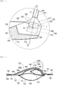
- Figs. 1 to 3 are diagrams for description of a hemostatic device 100 according to a first embodiment
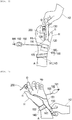
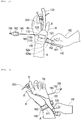
- Figs. 4 to 9 are diagrams for description of usage examples of the hemostatic device 100.
- a sheath tube of an introducer 200 indwelling at a puncture site t1 (corresponding to a site where bleeding is to be stopped) formed on a radial artery side (for example, an artery around an anatomical snuffbox or a distal radial artery running on a fingertip side of the snuffbox) of a palmar artery (deep palmar artery) B1 running on a side of a dorsal side Hb of a hand (for example, left hand or right hand) H located on the fingertip side of a forearm A of a patient, the hemostatic device 100 is used to perform hemostasis on the puncture site t1.
- the anatomical snuffbox is a cavity in the hand H located on the radial side of the forearm A when the patient spreads a thumb f1 of the hand H.
- the hemostatic device 100 includes a covering member 110 configured to be disposed to cover the puncture site t1 on the hand H of the patient, a plurality of securing members 151, 152, and 153 for securing the covering member 110 while the covering member 110 covers the puncture site t1, and an inflatable member 160 connected to the covering member 110 and configured to be inflated by injection of a fluid.
- a distal side of the hand H of the patient refers to a side where the fingertip of the hand H is disposed (upper side of Fig. 8 ).
- Figs. 1 and 2 are plan views of the hemostatic device 100 as viewed from an outer surface 120a side of a main body 120 of the covering member 110. Note that in each part of the hemostatic device 100, an “inner surface” is a surface on a side disposed to face a body surface of the patient when the hemostatic device 100 is attached to the patient, and an “outer surface” is a surface opposite to the inner surface (surface not disposed to face the body surface of the patient).
- the covering member 110 includes the main body 120 to which the inflatable member 160 is connected, a first arm portion 130 having a first securing member (corresponding to the securing member) 151 and protruding from the main body 120, and a second arm portion 140 having a second securing member (corresponding to the securing member) 152 and protruding from the main body 120 in a direction different from a longitudinal direction of the first arm portion 130.
- the hemostatic device 100 when the hemostatic device 100 is attached to the hand H of the patient to perform hemostasis, the first arm portion 130 is secured to the second arm portion 140 by passing between fingers f1 and f2 of the patient in a state where the second arm portion 140 is wrapped around a limb of the patient.
- the limb around which the second arm portion 140 is wrapped is, for example, a portion including a part of the forearm A and a part of a wrist.
- a space between the fingers (inter-finger portion) through which the first arm portion 130 passes is, for example, between the thumb f1 and an index finger f2 of the hand H of the patient.
- a position of the limb around which the second arm portion 140 is wrapped or a position of the inter-finger portion through which the first arm portion 130 is passed is not particularly limited.
- the first arm portion 130 is formed of a flexible band-shaped member that can extend from the side of the dorsal side Hb of the hand H to a palm Hp side of the hand H of the patient by passing between the thumb f1 and the index finger f2 when the hemostatic device 100 is attached to the hand H of the patient.
- a wide portion for facilitating holding of the first arm portion 130 by fingers is provided at an end portion of the first arm portion 130 disposed on the opposite side from the main body 120.
- the second arm portion 140 includes a belt portion 141 for wrapping the second arm portion 140 around the limb of the patient, and a support portion 143 located on a straight line c1, which connects the first arm portion 130 and the inflatable member 160, to connect the main body 120 of the covering member 110 and the belt portion 141 of the second arm portion 140.
- the straight line c1 can be defined as a straight line extending in parallel with an extending direction of the first arm portion 130 in a state where the first arm portion 130 and the second arm portion 140 are spread.
- the belt portion 141 of the second arm portion 140 is secured to the support portion 143 with the belt portion 141 wrapped around the limb of the patient.
- the belt portion 141 and the support portion 143 are secured by a third securing member 153 disposed on the belt portion 141 and the second securing member 152 disposed on the support portion 143 (see Fig. 9 ).
- the belt portion 141 is formed by a flexible band-shaped member that can be wrapped along a circumferential direction of the limb of the patient when the hemostatic device 100 is attached to the hand H of the patent.
- the support portion 143 is disposed on a proximal side (wrist side when viewed from the hand H and lower side of Fig. 5 ) of the hand H of the patent with respect to the inflatable member 160.
- the belt portion 141 and the support portion 143 are integrally formed by one member.
- the belt portion 141 and the support portion 143 may be configured by connecting two or more members.
- the hemostatic device 100 can be configured such that an angle ⁇ between the first arm portion 130 and the second arm portion 140 is 90° to 150° in a state where the arm portions 130 and 140 are extended substantially linearly before attaching the hemostatic device 100 to the patient.
- a direction in which each of the arm portions 130 and 140 protrudes from the main body 120 is not particularly limited as long as the inflatable member 160 can be disposed at the puncture site t1 in a state where the first arm portion 130 is disposed between predetermined fingers and the second arm portion 140 is wrapped around the limb.
- a proximal end of the first arm portion 130 (end portion of the first arm portion 130 on the main body 120 side) can be disposed at a position 200 mm to 250 mm away from a marker portion 105 of the main body 120.
- a width of the first arm portion 130 can be formed to be 5 mm to 20 mm.
- a proximal end of the second arm portion 140 (end portion of the second arm portion 140 on the main body 120 side) can be disposed at a position 250 mm to 350 mm away from the marker portion 105 of the main body 120.
- the main body 120 of the covering member 110 has a first region 121 and a second region 122 which is formed in a part different from the first region 121 and on which the inflatable member 160 is disposed.
- the second region 122 of the main body 120 has a support member 125 having a higher rigidity than that of the first region 121 of the main body 120.
- the first region 121 of the main body 120 is disposed to surround the support member 125 having a higher rigidity than that of the first region 121. That is, the support member 125 is surrounded by the first region 121 that is more flexible than the support member 125.
- the inflatable member 160 (a first inflatable portion 170 and a second inflatable portion 180) located on the inner surface side of the support member 125 inflates in the second region 122, an inflating force from the inside to the outside of the inflatable member 160 is hardly transmitted from the support member 125 to the first region 121, and thus it is possible to suppress formation of a gap between a surface of the dorsal side Hb of the hand H of the patient and the main body 120 at a peripheral edge of the main body 120.
- the first region 121 of the main body 120 is disposed to surround the periphery of the second region 122 of the main body 120.
- the support member 125 is inserted into an insertion portion 128a disposed on an outer surface side of the second region 122 (surface opposite to a side where each of the inflatable portions 170 and 180 is disposed in the second region 122, which is a surface on an upper side of Fig. 3 ).
- the insertion portion 128a is a space formed between the cover member 128 disposed to cover a part of the outer surface of the main body 120 and the main body 120. Note that the insertion portion 128a is not illustrated except for the drawings of Figs. 3 and 9 .
- An opening (not illustrated) is formed between the main body 120 and the insertion portion 128a on a side portion side intersecting the straight line c1 on the plan view illustrated in Fig. 2 .
- the insertion portion 128a communicates with the outside through the opening.
- the support member 125 can be inserted into the insertion portion 128a through the opening.
- the cover member 128 can be connected to the covering member 110, for example, by adhesion or welding.
- the support member 125 has a curved portion 125a formed on the first arm portion 130 side.
- the curved portion 125a has a cross-sectional shape that protrudes upward so as to be separated from the main body 120 on the cross-sectional view illustrated in Fig. 3 .
- the first arm portion 130 side means a side close to the first arm portion 130 with reference to a center position (position where the marker portion 105 is disposed in the present embodiment) on the plan view of the inflatable member 160 illustrated in Fig. 2 .
- the support member 125 has an inclined portion 125b extending from the curved portion 125a toward the support portion 143 side.
- the inclined portion 125b extends substantially linearly toward the support portion 143 side.
- the support member 125 may be disposed on the inner surface side of the main body 120 of the covering member 110 (surface on which each of the inflatable portions 170 and 180 is disposed, which is a surface on a lower side of Fig. 3 ).
- each of the inflatable portions 170 and 180 can be secured to the support member 125, for example.
- connection of the cover member 128 to the main body 120 can be omitted.
- the peripheral edge of the main body 120 includes a sheath indwelling portion 129 having a shape recessed in a plan view toward the curved portion 125a side of the support member 125 at a position on the distal side (fingertip side) of an extension line of a straight line L1 (see Fig. 2 ) passing through an apex 125c (a portion where the curved portion 125a is most distant from an inner surface of the inflatable member 160 in a state before the inflatable member 160 is inflated) of the curved portion 125a of the support member 125 between the first arm portion 130 and the second arm portion 140.
- the curved portion 125a of the support member 125 forms a convex portion protruding in a direction away from the inflatable member 160 on the main body 120 of the covering member 110 in the state before the inflatable member 160 is inflated.
- the sheath indwelling portion 129 is recessed toward the curved portion 125a side of the support member 125 forming the convex portion on the main body 120, so that a distance between the peripheral edge of the main body 120 and the curved portion 125a is shortened.
- a gap portion is likely to be formed between the surface of the dorsal side Hb of the hand H of the patient and the covering member 110.
- an operator attaches the hemostatic device 100 such that the sheath tube of the introducer 200 (see Figs. 5 and 6 ) is located at the sheath indwelling portion 129 of the main body 120, so that the sheath tube can be easily removed even after the inflatable member 160 of the hemostatic device 100 is inflated.
- the inflatable member 160 when the inflatable member 160 is inflated, the curved portion 125a side of the support member 125 wraps the end portion of the inflatable member 160 on the first arm portion 130 side, so that the compressive force of the inflatable member 160 is directed toward the center side of the support member 125.
- the compressive force of the inflatable member 160 is inhibited from escaping to the outside of the support member 125.
- the first region 121 and the second region 122 of the main body 120 are integrally formed by one member. However, the first region 121 and the second region 122 may be configured by connecting different members.
- a portion overlapping the marker portion 105 in the plan view illustrated in Fig. 2 and surroundings thereof are preferably transparent (including colored transparent, colorless transparent, and translucent).
- the covering member 110 includes the main body 120, the first arm portion 130, and the second arm portion 140 (the belt portion 141 and the support portion 143), each of which is a separate member.
- each of the main body 120, the first arm portion 130, and the second arm portion 140 can be connected by, for example, adhesion, welding, etc.
- the main body 120 is preferably made of a material different from that of the first arm portion 130 and the second arm portion 140. In this way, the main body 120 is easily deformed due to a change in physical property at each boundary between the first arm portion 130 and the second arm portion 140, and thus the first arm portion 130 and the second arm portion 140 can be easily disposed on the patient in a state where the main body 120 is disposed at the puncture site t1 formed on the hand H of the patient.
- a material of the main body 120 is preferably more rigid than materials of the first arm portion 130 and the second arm portion 140. In this way, when the inflatable member 160 is inflated, the main body 120 can suppress rising of the main body 120 by the inflatable member 160 due to the rigidity of the main body 120.
- the first arm portion 130 and the second arm portion 140 are configured to be more flexible than the main body 120, so that when the hemostatic device 100 is attached to the patient, the covering member 110 can be easily attached along the shape of the hand H of the patient.
- the main body 120, the first arm portion 130, and the second arm portion 140 are configured as different members, respectively.
- any part of the main body 120, the first arm portion 130, and the second arm portion 140 may be integrally formed of one member.
- the material used for the main body 120 of the covering member 110 is not particularly limited. Examples thereof include polyvinyl chloride, polyolefin such as polyethylene, polypropylene, polybutadiene, or ethylene-vinyl acetate copolymer (EVA), polyester such as polyethylene terephthalate (PET) or polybutylene terephthalate (PBT), polyvinylidene chloride, silicone, polyurethane, various thermoplastic elastomers such polyamide elastomer, polyurethane elastomer, and polyester elastomer, nylon, nylon elastomer, or any combination thereof (blended resin, polymer alloy, laminate, etc.).
- polyvinyl chloride polyolefin such as polyethylene, polypropylene, polybutadiene, or ethylene-vinyl acetate copolymer (EVA)
- PET polyethylene terephthalate
- PBT polybutylene terephthalate
- polyvinylidene chloride
- the material used for the cover member 128 is not particularly limited, and examples thereof include the same materials as those exemplified as the material of the covering member 110.
- the material used for the support member 125 has a higher rigidity than that of the material used for the first region 121 of the main body 120 of the covering member 110.
- a material include acrylic resin, polyvinyl chloride (especially hard polyvinyl chloride), polyolefin such as polyethylene, polypropylene, or polybutadiene, polystyrene, poly-(4-methylpentene-1), polycarbonate, ABS resin, polymethylmethacrylate (PMMA), polyacetal, polyacrylate, polyacrylonitrile, polyvinylidene fluoride, ionomer, acrylonitrile-butadiene-styrene copolymer, polyester such as polyethylene terephthalate (PET) or polybutylene terephthalate (PBT), butadiene-styrene copolymer, aromatic or aliphatic polyamide, fluorine-based resin such as polytetrafluoroethylene, etc.
- PET polyethylene terephthalate
- the material used for the first arm portion 130 and the second arm portion 140 of the covering member 110 is not particularly limited. Examples thereof may include the same materials as the materials exemplified as the main body 120 of the covering member 110, woven fabric, nonwoven fabric, felt, cloth, knitted fabric, and paper.
- the first securing member 151 is disposed on the inner surface of the first arm portion 130.
- the first securing member 151 is formed on a female side of a surface fastener.
- the second securing member 152 is disposed on an outer surface of the second arm portion 140 (an outer surface of the belt portion 141 and an outer surface of the support portion 143).
- the second securing member 152 is formed on a male side of the surface fastener.
- the third securing member 153 is disposed on an inner surface of the second arm portion 140 (an inner surface of the belt portion 141 and an inner surface of the support portion 143).
- the third securing member 153 is formed on the female side of the surface fastener.
- each of the securing members 151, 152, and 153 is not limited as long as the second arm portion 140 wrapped around the limb of the patient can be secured to the support portion 143, and the first arm portion 130 passed between the thumb f1 and the index finger f2 can be secured to the second arm portion 140.
- the male side and the female side of the surface fastener may be interchanged.
- the surface fastener is a fastener that is removable in terms of surface, and is, for example, Magic Tape (registered trademark) or Velcro (registered trademark) .
- each of the securing members 151, 152, and 153 may be a snap, a button, a clip, a member 529 having a hole 529a as described in the embodiments described later (see Fig. 12 ), etc.
- the inflatable member 160 has the first inflatable portion 170 and a deformable auxiliary member 180 having a smaller outer shape (outer shape on the plan view of Fig. 2 ) than that of the first inflatable portion 170.
- the auxiliary member 180 is disposed to overlap the first inflatable portion 170 on the first arm portion 130 side of the first inflatable portion 170.
- the first arm portion 130 side means a side close to the first arm portion 130 with reference to a center position (position where the marker portion 105 is disposed in the present embodiment) on the plan view of the inflatable member 160 illustrated in Fig. 2 .
- the first inflatable portion 170 has a lumen 171 into which a fluid can be injected, and a communication hole 172 formed at a position facing the auxiliary member 180.
- the auxiliary member 180 is a second inflatable portion that is inflated by injection of a fluid.
- the auxiliary member 180 is referred to as a second inflatable portion.
- the second inflatable portion 180 has a lumen 181 into which a fluid can be injected, and a communication hole 182 formed at a position facing the first inflatable portion 170.
- the lumen 181 of the second inflatable portion 180 communicates with the lumen 171 of the first inflatable portion 170 through the communication hole 182 of the second inflatable portion 180 and the communication hole 172 of the first inflatable portion 170.
- the inflatable member 160 is fixed to the covering member 110 on the curved portion 125a side of the support member 125.
- the second inflatable portion 180 is fixed to the inner surface of the covering member 110 (the inner surface of the main body 120 of the covering member 110) .
- An end portion 183 located on the first arm portion 130 side of the second inflatable portion 180 is fixed to the inner surface of the covering member 110.
- the first inflatable portion 170 is connected to the second inflatable portion 180 near a central portion excluding a peripheral edge of the second inflatable portion 180. In the first inflatable portion 170, only a certain range around each communication hole 182 located near the central portion of the second inflatable portion 180 is fixed to the second inflatable portion 180. For this reason, the first inflatable portion 170 is not directly connected to the covering member 110, and is indirectly connected to the covering member 110 via the second inflatable portion 180.
- the inflatable member 160 may be fixed to the inner surface of the covering member 110 at a position different from that in Fig. 3 as long as the inflatable member 160 is fixed to the covering member 110 on the curved portion 125a side of the support member 125.
- a part or the whole of the outer surface side of the second inflatable portion 180 may be fixed to the inner surface of the covering member 110 on the curved portion 125a side of the support member 125.
- the first inflatable portion 170 has a substantially square shape on the plan view illustrated in Fig. 2 .
- the second inflatable portion 180 has a substantially rectangular shape that includes a set of long sides having substantially the same length as that of one side of the first inflatable portion 170 and a set of short sides having a length which is approximately half a length of one side of the first inflatable portion 170.
- the lumen 181 of the second inflatable portion 180 communicates with a lumen of a tube 193 for supplying a fluid such as air to the second inflatable portion 180.
- the tube 193 is connected to the second inflatable portion 180 on the second arm portion 140 side of the second inflatable portion 180.
- the tube 193 is pulled out to the outside of the main body 120 through the inner surface side of the main body 120 of the covering member 110.
- a position where the tube 193 is pulled out from the second inflatable portion 180 is not particularly limited. However, as illustrated in Fig.
- the tube 193 when the tube 193 is pulled out to the second arm portion 140 side, so that the hemostatic device 100 is attached to the patient, the tube 193 is disposed laterally to the hand H (in a direction intersecting a direction in which the finger of the hand H extends) (see Fig. 5 ). For this reason, when the hemostatic device 100 is attached to the patient, the tube 193 can be prevented from interfering with the introducer 200.
- the hemostatic device 100 has the marker portion 105 for aligning the inflatable member 160 with respect to the puncture site t1.
- the marker portion 105 is disposed at a position corresponding to a substantially center position (center position on the plan view illustrated in Fig. 2 ) of the first inflatable portion 170.
- the marker portion 105 can be disposed on an inner surface of a side surface (inner surface) of the first inflatable portion 170 disposed to face the body surface.
- the marker portion 105 may be disposed on an internal surface of a surface (outer surface) opposite to the side surface of the first inflatable portion 170 disposed to face the body surface or an external surface thereof, an internal surface or an external surface of the main body 120 of the covering member 110, an internal surface or an external surface of the support member 125, an internal surface or an external surface of the cover member 128, etc.
- the marker portion 105 may be disposed on an external surface of the end portion of the second inflatable portion 180.
- the marker portion 105 preferably includes a transparent central portion and a colored linear frame portion surrounding the central portion.
- the operator can dispose the marker portion 105 at the puncture site t1 while confirming the puncture site t1 through the transparent central portion of the marker portion 105. For this reason, the operator can easily dispose the center position of the first inflatable portion 170 at the puncture site t1 using the marker portion 105.
- the marker portion 105 may be formed only by the colored central portion without having the frame portion. Further, a specific shape and color of the marker portion 105, a formation method on each portion of the hemostatic device 100, etc. are not particularly limited.
- the first inflatable portion 170 is formed of two sheet-shaped members.
- the first inflatable portion 170 can be formed by forming the lumen 171 between two sheet-shaped members formed in a substantially rectangular shape and bonding outer peripheral edges of the two sheet-shaped members in this state.
- the second inflatable portion 180 can be formed of two substantially rectangular sheet-shaped members bonded together.
- a method of bonding the sheet-shaped members forming the first inflatable portion 170, and a method of bonding the sheet-shaped members forming the second inflatable portion 180 are not particularly limited. For example, it is possible to adopt adhesion or welding. Further, a method of connecting the second inflatable portion 180 and the main body 120 of the covering member 110 is not particularly limited. For example, adhesion or welding can be adopted. Further, a method of securing the periphery of the communication hole 172 of the first inflatable portion 170 and the periphery of the communication hole 182 of the second inflatable portion 180 is not particularly limited. For example, adhesion or welding can be adopted.
- first inflatable portion 170 and the second inflatable portion 180 may not have a structure in which a plurality of sheet-shaped members is bonded.
- the first inflatable portion 170 and the second inflatable portion 180 may be formed of, for example, one bag-shaped member in which a space into which a fluid can flow is formed.
- a material used for the first inflatable portion 170 and the second inflatable portion 180 is not particularly limited, and examples thereof may include the same materials as those exemplified as the material of the covering member 110.
- the hemostatic device 100 has an injection portion 191 for injecting a fluid into the inflatable member 160 (the first inflatable portion 170 and the second inflatable portion 180).
- the injection portion 191 includes a connector having an incorporated check valve (not illustrated) .
- a syringe (not illustrated) can be connected to the injection portion 191.
- a cushioning member 192 having an inflatable space is disposed between the injection portion 191 and the inflatable member 160.
- the cushioning member 192 includes a flexible bag-shaped member having a space formed inside. Note that as illustrated in Fig. 1 , the cushioning member 192 may be provided with an arrow-shaped marker indicating a direction in which the syringe is inserted into the injection portion 191.
- the injection portion 191 is connected to one end side of the cushioning member 192.
- a lumen of the injection portion 191 communicates with a space in the cushioning member 192.
- the check valve incorporated in the injection portion 191 is closed, communication between the lumen of the injection portion 191 and the space in the cushioning member 192 is cut off.
- a flexible tube 193 is connected to the other end side of the cushioning member 192.
- a lumen of the tube 193 communicates with the space in the cushioning member 192.
- the other end portion opposite to one end portion connected to the cushioning member 192 is connected to the second inflatable portion 180.
- the lumen of the tube 193 communicates with the lumen 181 of the second inflatable portion 180.
- the other end portion of the tube 193 can be connected to the second inflatable portion 180 using an adhesive, etc. while being interposed between the two sheet-shaped members forming the second inflatable portion 180.
- the sheet-shaped members forming the second inflatable portion 180 for example, convex portions partially protruding outward from the sheet-shaped members may be formed at parts interposing the tube 193 therebetween.
- the operator inserts a distal tubular portion of a syringe (not illustrated) into the injection portion 191 to open the check valve.
- the operator injects air in the syringe into the lumen 181 of the second inflatable portion 180 by pushing a plunger of the syringe with the check valve of the injection portion 191 open.
- the second inflatable portion 180 When air is injected into the lumen 181 of the second inflatable portion 180, the second inflatable portion 180 inflates. Further, the air injected into the lumen 181 of the second inflatable portion 180 flows into the lumen 171 of the first inflatable portion 170 via the communication hole 182 of the second inflatable portion 180 and the communication hole 172 of the first inflatable portion 170. When air flows into the lumen 171 of the first inflatable portion 170, the first inflatable portion 170 inflates. When the first inflatable portion 170 and the second inflatable portion 180 inflate, the cushioning member 192 communicating with the lumen 181 of the second inflatable portion 180 via the tube 193 inflates.
- the space in cushioning member 192 and the lumen 181 of the second inflatable portion 180 are in communication with each other via the tube 193 at all times .
- the injection portion 191 maintains the check valve incorporated in the injection portion 191 in a closed state when the syringe is not inserted into the injection portion 191 to prevent air from leaking from the injection portion 191.
- the air in the lumen 171 of the first inflatable portion 170 and the lumen 181 of the second inflatable portion 180 moves to the cushioning member 192 side which is not pressed against the puncture site t1 by the covering member 110. In this way, the compressive force applied to the puncture site t1 by the inflatable member 160 is adjusted, and thus the compressive force to the puncture site t1 by the inflatable member 160 can be appropriately maintained.
- the operator contracts the first inflatable portion 170 and the second inflatable portion 180, the operator inserts the distal tubular portion of the syringe into the injection portion 191 and pulls the plunger of the syringe.
- the operator can discharge the air in the first inflatable portion 170 and the air in the second inflatable portion 180 to the syringe.
- the operator, etc. when the operator, etc. inflates the inflatable member 160, the operator, etc. can visually confirm that the first inflatable portion 170 and the second inflatable portion 180 can be pressurized without leakage of air by confirming expansion of the cushioning member 192.
- Fig. 4 illustrates a state after performing various procedures by inserting the sheath tube of the introducer 200 into the distal radial artery side of the palmar artery B1 via the puncture site t1 (see Fig. 9 ) formed on the dorsal side Hb of the hand (left hand) H of the patient.
- Fig. 4 illustrates a state in which a part of the sheath tube of the introducer 200 is pulled out from the puncture site t1 after completing the above procedure.
- the operator, etc. disposes the main body 120 of the covering member 110 so as to overlap the side of the dorsal side Hb of the hand H.
- the marker portion 105 formed at a substantially center position of the first inflatable portion 170 is disposed at the puncture site t1.
- a hand H2 illustrated in Figs. 4 to 7 indicates a hand of the operator, etc. who attaches the hemostatic device 100 to the patient.
- the operator, etc. wraps the belt portion 141 of the second arm portion 140 along the limb of the patient to overlap the belt portion 141 on the support portion 143.
- the operator, etc. brings the third securing member (female side of the surface fastener) 153 disposed on the inner surface side of the belt portion 141 into contact with the second securing member (male side of the surface fastener) disposed on the outer surface side of the support portion 143 to secure the support portion 143 and the belt portion 141 via the respective securing members 152 and 153.
- the operator, etc. passes the first arm portion 130 between the thumb f1 and the index finger f2 of the hand H of the patient. Then, as illustrated in Fig. 7 , the operator, etc. overlaps a part of the first arm portion 130 on the belt portion 141 near the limb of the patient on the palm Hp side of the hand H of the patient. The operator, etc.
- the operator, etc. connects the syringe to the injection portion 191, and injects air into the second inflatable portion 180 to inflate the first inflatable portion 170 and the second inflatable portion 180.
- the first inflatable portion 170 applies a compressive force to the puncture site t1.
- the operator, etc. removes the sheath tube of the introducer 200 from the puncture site t1.
- the operator, etc. confirms that there is no bleeding from the puncture site t1 while hemostasis is performed using the hemostatic device 100.
- the amount of air injected into the respective inflatable portions 170 and 180 is adjusted.
- the operator, etc. gradually depressurizes the respective inflatable portions 170 and 180 to confirm that hemostasis at the puncture site t1 is properly performed. After the hemostasis at the puncture site t1 is completed, the operator, etc. sufficiently depressurizes the respective inflatable portions 170 and 180. Then, the operator, etc. releases securing of the hemostatic device 100 by the first arm portion 130 and the second arm portion 140, and removes the hemostatic device 100 from the hand H of the patient.
- the hemostatic device 100 is firmly secured to the hand H of the patient by the first arm portion 130 passed between the thumb f1 and index finger f2 of the hand H of the patient and the second arm portion 140 wrapped around the limb of the patient. For this reason, since each finger is not covered by the covering member 110 in a state where the hemostatic device 100 is attached to the hand H, the patient can freely move the finger while hemostasis is performed.
- the operator, etc. can easily attach the hemostatic device 100 to the hand H of the patient by proceeding with an attachment operation according to the procedure described with reference to Figs. 4 to 7 . Therefore, the operator can easily attach the hemostatic device 100 to the patient in a short time using the first arm portion 130 and the second arm portion 140. Further, the hemostatic device 100 can be secured to the hand H of the patient by securing the arm portions 130 and 140 to each other using the securing members 151, 152 and 153 disposed on the respective arm portions 130 and 140. Therefore, the hemostatic device 100 can prevent damage to the skin of the patient during attachment when compared to a hemostatic device secured to the hand H or the forearm A of the patient using a seal member provided with an adhesive material.
- the hemostatic device 100 since the hemostatic device 100 includes the first inflatable portion 170 as a member that applies a compressive force to the puncture site t1, the compressive force can be easily adjusted by adjusting the internal pressure of the first inflatable portion 170. Further, in the hemostatic device 100, even when the first inflatable portion 170 is deformed so as to change the internal pressure following movement of the hand H when the patient moves the hand H, the deformable second inflatable portion 180 mitigates the change in the internal pressure of the first inflatable portion 170. Therefore, the first inflatable portion 170 has a high following property to movement of the hand H of the patient, and compression on the puncture site t1 by the first inflatable portion 170 can be appropriately maintained.
- the hemostatic device 100 is configured to cover only a part of the dorsal side Hb of the hand H of the patient by the covering member 110, and is not configured to cover the entire hand H. For this reason, when the patient moves the hand H in a state where the hemostatic device 100 is attached to the hand H of the patient, it is possible to prevent movement of the hand H of the patient from being transmitted to the entire hemostatic device 100. Therefore, the hemostatic device 100 can suppress position shift from the hand H of the patient when the patient moves the hand H in the state where the hemostatic device 100 is attached to the hand H of the patient.
- the hemostatic device 100 can be attached to the right hand of the patient without changing the configuration of the hemostatic device 100.
- an attachment procedure is substantially the same as the procedure illustrated in Figs. 4 to 7 .
- the hemostatic device 100 includes the covering member 110 configured to be disposed to cover the puncture site t1 on the hand H of the patient, the securing members 151, 152, and 153 for securing the covering member 110 in a state where the covering member 110 covers the puncture site t1, and the inflatable member 160 connected to the covering member 110 and configured to be inflated by injection of a fluid.
- the covering member 110 includes the main body 120 to which the inflatable member 160 is connected, the first arm portion 130 protruding from the main body 120, and the second arm portion 140 protruding from the main body 120 in a direction different from the longitudinal direction of the first arm portion 130.
- the first arm portion 130 is configured to be secured to the second arm portion 140 by passing between the fingers f1 and f2 of the patient in a state where the second arm portion 140 is wrapped around the limb of the patient, the second arm portion 140 includes the belt portion 141 for wrapping around the limb of the patient and the support portion 143 located on the straight line c1 connecting the first arm portion 130 and the inflatable member 160 to connect the main body 120 and the belt portion 141, and the belt portion 141 is configured to be secured to the support portion 143 in a state of being wrapped around the limb of the patient.
- the hemostatic device 100 configured as described above can secure the main body 120, to which the inflatable member 160 is connected, to the puncture site t1 by wrapping the belt portion 141 of the second arm portion 140 around the limb of the patient. Further, in the hemostatic device 100, when the first arm portion 130 is secured to the second arm portion 140 by passing between the fingers f1 and f2 of the patient, it is possible to prevent the inflatable member 160 from rising on the distal side of the hand H while preventing position shift of the inflatable member 160.
- the hemostatic device 100 when the hemostatic device 100 is attached to the hand H of the patient, it is possible to prevent the inflatable member 160 from rising on the proximal side of the hand H by connecting the belt portion 141 of the second arm portion 140 to the support portion 143 located on the straight line c1 connecting the first arm portion 130 and the inflatable member 160. For this reason, in the hemostatic device 100, even when the patient moves the hand H in a state in which the inflatable member 160 is inflated, by securing the first arm portion 130 and the second arm portion 140 and securing the belt portion 141 and the support portion 143, rising of the distal side (fingertip side) and the proximal side (wrist side) of the main body 120 to which the inflatable member 160 is connected is prevented. Thus, it is possible to appropriately maintain the compressive force of the inflatable member 160 on the puncture site t1 formed on the dorsal side Hb of the hand H of the patient.
- the main body 120 of the covering member 110 has the first region 121 and the second region 122 which is formed in a part different from the first region 121 and in which the inflatable member 160 is disposed.
- the second region 122 has the support member 125 having a higher rigidity than that of the first region 121. Therefore, the hemostatic device 100 can prevent the inflatable member 160 from rising from the dorsal side Hb of the hand H of the patient by the support member 125 while hemostasis is performed. As a result, the hemostatic device 100 can suitably apply a compressive force from the inflatable member 160 to the puncture site t1 while being attached to the hand H of the patient.
- the first region 121 of the main body 120 is disposed to surround the periphery of the second region 122 of the main body 120.
- the support member 125 is inserted into the insertion portion 128a disposed on the outer surface side of the second region 122. Since the support member 125 is surrounded by the first region 121 which is more flexible than the support member 125, when the inflatable member 160 located in the second region 122 is inflated, a force expanding from the inside to the outside of the inflatable member 160 is hardly transmitted from the support member 125 to the first region 121. Therefore, the hemostatic device 100 can suppress formation of a gap between the surface of the dorsal side Hb of the hand H and the main body 120 at the peripheral edge of the main body 120.
- the hemostatic device 100 can be equipped with the support member 125 by a simple operation of inserting the support member 125 into the insertion portion 128a.
- the support member 125 has the curved portion 125a formed on the first arm portion 130 side of the support member 125. For this reason, in the support member 125, when the inflatable member 160 is inflated, a direction in which the inflatable member 160 applies a compressive force to the hand H of the patient is directed in an oblique direction toward the puncture site t1. For this reason, the hemostatic device 100 can more effectively apply a compressive force to the puncture site t1.
- the inflatable member 160 directs the compressive force toward the center side of the support member 125, and thus the compressive force of the inflatable member 160 is inhibited from escaping to the outside of the support member 125.
- the curved portion 125a presses the inflatable member 160 against the skin of the hand H of the patient, it is possible to prevent the inflatable member 160 from rising, and it is possible to suppress a decrease in the compressive force of the inflatable member 160 applied to the puncture site t1.
- the inflatable member 160 is secured to the covering member 110 on the curved portion 125a side of the support member 125. For this reason, in the inflatable member 160 (the first inflatable portion 170 and the second inflatable portion 180), by securing the inflatable member 160 and the support member 125, position shift of the inflatable member 160 with respect to the curved portion 125a of the support member 125 is prevented, and thus the compressive force of the curved portion 125a on a portion close to the first arm portion 130 becomes stronger. As a result, in the hemostatic device 100, even when a gap is generated between the first arm portion 130 and the surface of the hand H due to bending of the thumb f1 or the wrist of the patient, it is possible to prevent a decrease in the compressive force by the inflatable member 160.
- the inflatable member 160 has the first inflatable portion 170 and the deformable auxiliary member 180 having a smaller outer shape than that of the first inflatable portion 170, and the auxiliary member 180 is disposed to overlap the first inflatable portion 170 on the first arm portion 130 side of the first inflatable portion 170.
- the second inflatable portion 180 inhibits the first inflatable portion 170 from rising from the body surface of the patient. Therefore, when the first inflatable portion 170 inflates, the first inflatable portion 170 can effectively apply the compressive force to the puncture site t1.
- the hemostatic device 100 when the patient bends a finger (for example, the thumb f1) or the wrist downward (to the palm Hp side of the hand H), the hemostatic device 100 maintains a state in which the auxiliary member 180 is deformed by following movement of the finger or the wrist and the auxiliary member 180 applies the compressive force to the puncture site t1. Further, in the hemostatic device 100, when the patient bends a finger (for example, the thumb f1) or the wrist upward (to the side of the dorsal side Hb of the hand H), the auxiliary member 180 is deformed following movement of the finger or the wrist, and the compressive force applied from the auxiliary member 180 to the puncture site t1 is weakened. Therefore, while hemostasis is performed by the hemostatic device 100, the hemostatic device 100 can maintain a state in which an appropriate compressive force is applied to the puncture site t1 while allowing the patient to move the finger or the wrist relatively freely.
- the auxiliary member 180 is the second inflatable portion 180 configured to be inflated by injection of a fluid, and the lumen 181 of the second inflatable portion 180 communicates with the lumen 171 of the first inflatable portion 170. Since the auxiliary member 180 includes the second inflatable portion 180 which is inflatable, it is possible to improve the following property of the second inflatable portion 180 to movement of the hand H. Further, since the lumen 171 of the first inflatable portion 170 and the lumen 181 of the second inflatable portion 180 communicate with each other, the first inflatable portion 170 and the second inflatable portion 180 can be easily inflated.
- the hemostatic device 100 has the injection portion 191 for injecting a fluid into the inflatable member 160.
- the cushioning member 192 having an inflatable space is disposed between the injection portion 191 and the inflatable member 160.
- the cushioning member 192 included in the hemostatic device 100 allows air to move from the lumen of the inflatable member 160 to the cushioning member 192 when the patient moves the hand H. Therefore, it is possible to prevent the movable range from being restricted by the inflatable member 160 when the patient moves the hand H. Note that when the patient returns the hand H from the deformed state to the original state, air moves from the cushioning member 192 to the inflatable member 160. Therefore, the compressive force can be effectively applied to the puncture site t1 from the inflatable member 160.
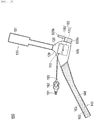
- Fig. 10 illustrates a hemostatic device 300 according to the modification.
- an inflatable member 160 only includes a first inflatable portion 170. That is, the inflatable member 160 does not include the second inflatable portion 180.
- the inflatable member 160 can effectively apply a compressive force to the puncture site t1.
- the first inflatable portion 170 is directly fixed to an inner surface of a covering member 110. Further, a tube 193 is connected so as to communicate with a lumen 171 of the first inflatable portion 170.
- Other configurations of the hemostatic device 300 are substantially the same as those of the hemostatic device 100 described above.
- Fig. 11 illustrates a hemostatic device 400 according to the second embodiment.
- a second arm portion 140 does not include the support portion 143.
- the hemostatic device 400 differs from the hemostatic device 100 according to the first embodiment.
- the operator wraps a belt portion 141 of the second arm portion 140 around the limb of the patient.
- the operator brings a third securing portion (female side of a surface fastener) 153 disposed on an inner surface of the belt portion 141 into contact with a second securing portion (male side of the surface fastener) 152 disposed on an outer surface of the belt portion 141, thereby securing the respective securing members 152 and 153.
- the operator, etc. holds the belt portion 141 in a state of being wrapped around the limb of the patient by securing the respective securing members 152 and 153.
- the operator can attached the hemostatic device 400 to the hand H of the patient by securing the first arm portion 130 to the second arm portion 140 according to a similar procedure (see Figs. 6 and 7 ) to the procedure described in the above embodiment.
- the hemostatic device 400 includes a covering member 110 configured to be disposed to cover the puncture site t1 on the hand H of the patient, securing members 151, 152, and 153 for securing the covering member 110 in a state where the covering member 110 covers the puncture site t1, and an inflatable member 160 connected to the covering member 110 and configured to be inflated by injection of a fluid.
- the covering member 110 includes a main body 120 to which the inflatable member 160 is connected, a first arm portion 130 protruding from the main body 120, and a second arm portion 140 protruding from the main body 120 in a direction different from a longitudinal direction of the first arm portion 130.
- the first arm portion 130 is configured to be secured to the second arm portion 140 by passing between the fingers f1 and f2 of the patient in a state where the second arm portion 140 is wrapped around the limb of the patient.
- the inflatable member 160 has the first inflatable portion 170 and the deformable auxiliary member 180 having a smaller outer shape than that of the first inflatable portion 170, and the auxiliary member 180 is disposed to overlap the first inflatable portion 170 on the first arm portion 130 side of the first inflatable portion 170.
- the main body 120 to which the first inflatable portion 170 is connected can be secured to the puncture site t1 by wrapping the second arm portion 140 around the limb of the patient. Further, the hemostatic device 400 can prevent the first inflatable portion 170 from rising on the distal side of the hand H while preventing the first inflatable portion 170 from being shifted by securing the first arm portion 130 to the second arm portion 140 through between the fingers f1 and f2 of the patient. Further, when the first inflatable portion 170 inflates, the hemostatic device 400 inhibits the first inflatable portion 170 from rising in a direction away from the puncture site t1 on the hand H of the patient by the auxiliary member 180.
- the hemostatic device 400 can appropriately secure the first inflatable portion 170 and the auxiliary member 180 to the puncture site t1. Further, in the hemostatic device 400, when the first inflatable portion 170 inflates, the auxiliary member 180 inhibits the first inflatable portion 170 from rising in the direction away from the puncture site t1 of the hand H of the patient, and thus it is unnecessary to secure to firmly tighten the first arm portion 130 passing between the fingers f1 and f2 of the patient to the second arm portion 140. In this way, the patient can move the finger or the wrist relatively freely in a state where the hemostatic device 400 is attached.
- the hemostatic device 400 when the patient bends a finger (for example, the thumb f1) or the wrist downward (the palm Hp side of the hand H), the hemostatic device 400 maintains a state in which the auxiliary member 180 is deformed by following movement of the finger or the wrist and the auxiliary member 180 applies the compressive force to the puncture site t1. Further, in the hemostatic device 400, when the patient bends a finger (for example, the thumb f1) or the wrist upward (to the side of the dorsal side Hb of the hand H), the auxiliary member 180 is deformed following movement of the finger or the wrist, and the compressive force applied from the auxiliary member 180 to the puncture site t1 is weakened. Therefore, while hemostasis is performed by the hemostatic device 400, the hemostatic device 400 can maintain a state in which an appropriate compressive force is applied to the puncture site t1 while allowing the patient to move the finger or the wrist relatively freely.
- the main body 120 of the covering member 110 has the first region 121 and the second region 122 which is formed in a part different from the first region 121 and in which the inflatable member 160 is disposed.
- the second region 122 has the support member 125 having a higher rigidity than that of the first region 121. Therefore, the hemostatic device 400 can prevent the inflatable member 160 from rising from the dorsal side Hb of the hand H of the patient by the support member 125 while hemostasis is performed.
- the inflatable member 160 can suitably apply a compressive force to the puncture site t1 in a state of being attached to the hand H of the patient.
- the first region 121 of the main body 120 is disposed to surround the periphery of the second region 122 of the main body 120.
- the support member 125 is inserted into the insertion portion 128a disposed on the outer surface side of the second region 122. Since the support member 125 is surrounded by the first region 121 which is more flexible than the support member 125, when the inflatable member 160 located in the second region 122 is inflated, a force expanding from the inside to the outside of the inflatable member 160 is hardly transmitted from the support member 125 to the first region 121. Therefore, the hemostatic device 400 can suppress formation of a gap between the surface of the hand H of the patient and the main body 120 at the peripheral edge of the main body 120.
- the hemostatic device 400 can be equipped with the support member 125 by a simple operation of inserting the support member 125 into the insertion portion 128a.
- the support member 125 has the curved portion 125a formed on the first arm portion 130 side of the support member 125. For this reason, in the support member 125, when the inflatable member 160 is inflated, a direction in which the inflatable member 160 applies a compressive force to the hand H of the patient is directed in an oblique direction toward the puncture site t1. For this reason, the hemostatic device 100 can more effectively apply a compressive force to the puncture site t1.
- the inflatable member 160 directs the compressive force toward the center side of the support member 125, and thus the compressive force of the second inflatable portion 180 is inhibited from escaping to the outside of the support member 125.
- the curved portion 125a presses the second inflatable portion 180 against the skin, it is possible to prevent the first inflatable portion 170 from rising, and it is possible to suppress a decrease in the compressive force of the inflatable member 160 applied to the puncture site t1.
- the inflatable member 160 is fixed to the covering member 110 on the first arm portion 130 side.
- the second inflatable portion 180 of the inflatable member 160 is fixed to the covering member 110 on the first arm portion 130 side.
- the inflatable member 160 (second inflatable portion 180) is fixed to the covering member 110 on the first arm portion 130 side, so that when the inflatable member 160 inflates, the direction in which the inflatable member 160 applies the compressive force to the hand H of the patient is directed in an oblique direction toward the puncture site t1. Therefore, the hemostatic device 100 can more effectively apply the compressive force to the puncture site t1.
- the inflatable member 160 is fixed to the covering member 110 on the curved portion 125a side of the support member 125. For this reason, in the inflatable member 160 (the first inflatable portion 170 and the second inflatable portion 180), position shift with respect to the curved portion 125a of the support member 125 of the inflatable member 160 is prevented by securing the inflatable member 160 and the support member 125, and thus a compressive force of the curved portion 125a on a position close to the first arm portion 130 becomes stronger. In this way, even when a gap is created between the surface of the first arm portion 130 and the surface of the hand H due to bending of the thumb f1 or the wrist of the patient, the hemostatic device 100 can prevent a decrease in the compressive force by the inflatable member 160.
- the auxiliary member 180 is a second inflatable portion 180 configured to be inflated by injection a fluid, and the lumen 181 of the second inflatable portion 180 communicates with the lumen 171 of the first inflatable portion 170. Since the auxiliary member 180 includes the second inflatable portion 180 which is inflatable, it is possible to improve the following property of the second inflatable portion 180 to movement of the hand H. Further, since the lumen 171 of the first inflatable portion 170 and the lumen 181 of the second inflatable portion 180 communicate with each other, the first inflatable portion 170 and the second inflatable portion 180 can be easily inflated.
- first inflatable portion 170 and the second inflatable portion 180 have communication holes 172 and 182 communicating with the lumen 171 of the first inflatable portion 170 and the lumen 181 of the second inflatable portion 180, respectively.
- first inflatable portion 170 only a certain range around each of the communication holes 172 and 182 is fixed to the second inflatable portion 180.
- first inflatable portion 170 only a certain range around each of the communication holes 172 and 182 located near the central portion of the second inflatable portion 180 is fixed to the second inflatable portion 180.
- the first inflatable portion 170 is not directly connected to the covering member 110, and is indirectly connected to the covering member 110 via the second inflatable portion 180.
- the hemostatic device 400 can maintain a large area in which the second inflatable portion 180 compresses the first inflatable portion 170. Therefore, the hemostatic device 400 can effectively apply a compressive force to the puncture site t1 from the inflatable member 160.
- the hemostatic device 400 has an injection portion 191 for injecting a fluid into the inflatable member 160.
- a cushioning member 192 having an inflatable space is disposed between the injection portion 191 and the inflatable member 160.
- the patient has a limited movable range of the hand H.
- the cushioning member 192 included in the hemostatic device 400 allows air to move from the lumen of the inflatable member 160 to the cushioning member 192 when the patient moves the hand H. Therefore, it is possible to prevent the movable range from being restricted by the inflatable member 160 when the patient moves the hand H. Note that when the patient returns the hand H from the deformed state to the original state, air moves from the cushioning member 192 to the inflatable member 160. Therefore, the compressive force can be effectively applied to the puncture site t1 from the inflatable member 160.
- Fig. 12 illustrates a hemostatic device 500 according to a first modification.
- the hemostatic device 500 according to the first modification has a securing auxiliary portion 529 disposed in the main body 120 of the covering member 110.
- the securing auxiliary portion 529 is disposed at a position different from a position where the first arm portion 130 is disposed and a position where the second arm portion 140 is disposed in the main body 120.
- the securing auxiliary portion 529 is disposed at a position facing the second arm portion 140 with the main body 120 interposed therebetween.
- the securing auxiliary portion 529 is made of a material harder than that of the main body 120.
- a hole 529a through which the belt portion 141 of the second arm portion 140 can be inserted is formed in the securing auxiliary portion 529.
- the hole 529a is tilted at an angle along a side portion of the main body 120 (tilted from a diagonally upper left side to a diagonally lower right side in the figure) in a state of not being attached to the hand H of the patient. Since the hole 529a is tilted in this way, as illustrated in Fig. 13 , the operator, etc. can easily insert the belt portion 141 of the second arm portion 140 into the hole 529a at the time of attaching the hemostatic device 500 to the patient.
- the securing auxiliary portion 529 may have a hook structure that includes a hole and a slit communicating with the hole instead of the hole 529a. Further, the securing auxiliary portion 529 may have a hole formed in a flexible material.
- the hole 529a can be disposed so that one end portion of the hole 529a is located on the proximal side (right side in Fig. 12 ) of the curved portion 125a of the support member 125. Further, the hole 529a can be disposed so as to be substantially parallel to the first inflatable portion 170. By disposing the hole 529a in this way, a tightening force is easily transmitted to the first inflatable portion 170 when the belt portion 141 of the second arm portion 140 is wrapped around the limb of the patient.
- the securing auxiliary portion 529 can be connected to the main body 120 by adhesion or welding.
- the operator, etc. inserts the belt portion 141 of the second arm portion 140 into the hole 529a of the securing auxiliary portion 529.
- the operator, etc. folds back the belt portion 141 through which the hole 529a of the securing auxiliary portion 529 is inserted toward the palm Hp side of the hand H of the patient. In a state where a part of the belt portion 141 is folded back, the operator, etc.
- the operator, etc. holds the belt portion 141 in a state of being wrapped around the limb of the patient by securing the respective securing members 152 and 153.
- the operator, etc. can attach the hemostatic device 500 to the hand H of the patient by securing the first arm portion 130 passing between the respective fingers f1 and f2 to the second arm portion 140.
- Fig. 15 illustrates a hemostatic device 600 according to a second embodiment.
- the hemostatic device 600 according to the second modification is different from the hemostatic device 500 according to the first modification described above in a configuration of securing auxiliary portions 629a and 629b.
- the first securing auxiliary portion 629a is connected to the main body 120.
- a male side of a surface fastener is disposed on an outer surface (outer surface on a plan view illustrated in Fig. 15 ) of the first securing auxiliary portion 629a.
- the second securing auxiliary portion 629b is connected to the first securing auxiliary portion 629a.
- a female side of the surface fastener is disposed on an outer surface (outer surface on the plan view illustrated in Fig. 15 ) of the second securing auxiliary portion 629b.
- the respective securing auxiliary portions 629a and 629b can be connected to the main body 120 by, for example, adhesion or welding. Note that installation of the second securing auxiliary portion 629b may be omitted as appropriate.
- the operator, etc. secures the third securing member (female side of the surface fastener) 153 disposed on the inner surface of the belt portion 141 of the second arm portion 140 to the first securing auxiliary portion 629a. Subsequently, the operator, etc. folds back the belt portion 141 toward the palm Hp side of the hand H of the patient using a portion of the belt portion 141 secured to the first securing auxiliary portion 629a as a base point.
- the third securing member female side of the surface fastener
- the operator, etc. disposes the female side of the surface fastener disposed on the outer surface of the second securing auxiliary portion 629b to cover a part of the belt portion 141 secured to the first securing auxiliary portion 629a, and secures the second securing auxiliary portion 629b to the belt portion 141.
- the operator, etc. wraps a folded part of the belt portion 141 around the limb toward the palm Hp side.
- the operator, etc. brings the third securing portion (female side of the surface fastener) 153 disposed on the inner surface of the belt portion 141 into contact with the second securing portion (male side of the surface fastener) 152 disposed on the outer surface of the belt portion 141, thereby securing the respective securing members 152 and 153.
- the operator, etc. holds the belt portion 141 in a state of being wrapped around the limb of the patient by securing the respective securing members 152 and 153.
- the operator, etc. can attach the hemostatic device 600 to the hand H of the patient by securing the first arm portion 130 passing between the respective fingers f1 and f2 to the second arm portion 140.
- hemostatic device according to the invention has been described above through the embodiments, the invention is not limited to content described in this specification, and can be appropriately modified based on description of the scope of claims.
- the hemostatic device for performing hemostasis at the puncture site formed on the dorsal side of the left hand has been exemplified.
- the hemostatic device can be used to perform hemostasis on a puncture site formed on a dorsal side of a right hand, a puncture site formed on a palm of the right hand, a puncture site formed on a palm of the left hand, etc.
- the auxiliary member is not limited to the inflatable member described in each embodiment.
- the auxiliary member may include a member made of a resin material such as plastic, gel, etc., a member containing gel whose moisture content decreases over time to gradually reduce a compressive force, an elastic material such as a sponge-like substance, an aggregate of fibers such as cotton, metal, a member having a predetermined three-dimensional shape (sphere, ellipsoid, triangular pyramid, etc.), an appropriate combination thereof, etc.
- each portion of the hemostatic device are not particularly limited as long as the inflatable member can be disposed at the puncture site, the first arm portion can be disposed between arbitrary fingers, and the second arm portion can be disposed on the limb, and changes can be made as appropriate.
Landscapes
- Health & Medical Sciences (AREA)
- Life Sciences & Earth Sciences (AREA)
- Surgery (AREA)
- Engineering & Computer Science (AREA)
- Animal Behavior & Ethology (AREA)
- Vascular Medicine (AREA)
- Nuclear Medicine, Radiotherapy & Molecular Imaging (AREA)
- Veterinary Medicine (AREA)
- Public Health (AREA)
- Biomedical Technology (AREA)
- Heart & Thoracic Surgery (AREA)
- Medical Informatics (AREA)
- Molecular Biology (AREA)
- Reproductive Health (AREA)
- General Health & Medical Sciences (AREA)
- Biophysics (AREA)
- Hematology (AREA)
- Surgical Instruments (AREA)
Abstract
Description
- The present invention relates to a hemostatic device.
- As a catheter procedure, a procedure is known in which a blood vessel (for example, radial artery) in an arm of a patient is punctured, and various medical elongated bodies are introduced into the blood vessel via a puncture site formed in the blood vessel in the arm of the patient so as to perform treatment or therapy on a lesion area (see PTL 1 below) . The catheter procedure utilizing the radial artery is referred to as transradial artery approach and is considered as a useful technique for, for example, coronary artery access and lower limb artery access.
- A radial artery located in an arm of a human body is connected to a palmar artery which bypasses a hand side. Therefore, currently, as a new method of transradial artery approach, a catheter procedure using distal transradial approach (dTRA) has been attempted to access the palmar artery (including a distal radial artery) from an anatomical snuffbox located on a dorsal side of the hand or from a position around the snuffbox, and perform treatment through the vascular access site.
- PTL 1:
JP-A-2008-119517 - Blood vessels such as palmar arteries located in the hand are located in places where there are many movable parts such as fingers. For this reason, a shape around the puncture site in the hand changes with movement of the hand. Therefore, when hemostasis is performed on the puncture site, a pressing member placed on the hand is preferably an inflatable member that follows the movement of the hand and can easily adjust a compressive force on the puncture site.
- However, when the pressing member is the inflatable member, the inflatable member exerts a force to inflate from the inside to the outside of the inflatable member in an inflated state. For this reason, in a hemostatic device having the inflatable member, when a shape around a hemostatic site changes due to the movement of the hand, and a large gap is created between the hemostatic device and the puncture site, the inflatable member rises, and it may not be possible to properly maintain the compressive force of the inflatable member on the puncture site. Therefore, when hemostasis is performed on the puncture site of the hand, the hemostatic device having the inflatable member needs to suppress rising by the inflatable member acting in a direction away from the puncture site and to appropriately secure the inflatable member to the puncture site. In this way, it is considered that the hemostatic device having the inflatable member can appropriately maintain the compressive force of the inflatable member on the puncture site even when the shape around the puncture site is changed by the movement of the hand.
- In view of the above problems, an object of the invention is to provide a hemostatic device capable of suppressing rising of an inflatable member from a site where bleeding is to be stopped on a hand and appropriately maintaining a compressive force of the inflatable member on the site where bleeding is to be stopped on the hand even when a patient moves the hand while the inflatable member is inflated.
- A hemostatic device according to an aspect of the invention includes a covering member configured to be disposed to cover a site where bleeding is to be stopped on a hand of a patient, a securing member configured to secure the covering member in a state where the covering member covers the site where bleeding is to be stopped, and an inflatable member connected to the covering member and configured to be inflated by injection of a fluid, in which the covering member includes a main body to which the inflatable member is connected, a first arm portion protruding from the main body, and a second arm portion protruding from the main body in a direction different from a longitudinal direction of the first arm portion, the first arm portion is configured to be secured to the second arm portion by passing between fingers of the patient in a state where the second arm portion is wrapped around a limb of the patient, the second arm portion has a belt portion for wrapping around the limb of the patient and a support portion located on a straight line connecting the first arm portion and the inflatable member to connect the main body and the belt portion, and the belt portion is configured to be secured to the support portion in a state of being wrapped around the limb of the patient.
- A hemostatic device according to another aspect of the invention includes a covering member configured to be disposed to cover a site where bleeding is to be stopped on a hand of a patient, a securing member configured to secure the covering member in a state where the covering member covers the site where bleeding is to be stopped, and an inflatable member connected to the covering member and configured to be inflated by injection of a fluid, in which the covering member includes a main body to which the inflatable member is connected, a first arm portion protruding from the main body, and a second arm portion protruding from the main body in a direction different from a longitudinal direction of the first arm portion, the first arm portion is configured to be secured to the second arm portion by passing between fingers of the patient in a state where the second arm portion is wrapped around a limb of the patient, the inflatable member has a first inflatable portion and a deformable auxiliary member having a smaller outer shape than an outer shape of the first inflatable portion, and the auxiliary member is disposed to overlap the first inflatable portion on a side of the first arm portion of the first inflatable portion.
- The hemostatic device according to the aspect of the invention can secure the main body, to which the inflatable member is connected, to the site where bleeding is to be stopped by wrapping the belt portion of the second arm portion around the limb of the patient. In addition, in the hemostatic device, when the first arm portion is secured to the second arm portion by passing between the fingers of the patient, it is possible to prevent the inflatable member from rising on the distal side of the hand while preventing position shift of the inflatable member. Further, when the hemostatic device is attached to the hand of the patient, it is possible to prevent the inflatable member from rising on the proximal side of the hand by connecting the belt portion of the second arm portion to the support portion located on the straight line connecting the first arm portion and the inflatable member. For this reason, in the hemostatic device, even when the hand is moved in a state in which the inflatable member is inflated, by securing the first arm portion and the second arm portion and securing the belt portion and the support portion, rising of the distal side (fingertip side) and the proximal side (wrist side) of the main body to which the inflatable member is connected is prevented. Thus, it is possible to appropriately maintain the compressive force of the inflatable member on the site where bleeding is to be stopped on the hand.
- The hemostatic device according to the other aspect of the invention can secure the main body, to which the first inflatable portion is connected, to the site where bleeding is to be stopped by wrapping the second arm portion around the limb of the patient. Further, the hemostatic device can prevent the inflatable portion from rising on the distal side of the hand while preventing the first inflatable portion from being shifted by securing the first arm portion to the second arm portion through between the fingers of the patient. Further, when the first inflatable portion inflates, the hemostatic device inhibits the first inflatable portion from rising in a direction away from the site where bleeding is to be stopped on the hand of the patient by the auxiliary member. For this reason, even when the hand is moved in a state in which the inflatable member is inflated, the hemostatic device can prevent rising on the distal side (fingertip side) of the main body to which the inflatable member is connected and the distal side (fingertip side) of the first inflatable portion at the distal side of the hand where the shape of the hand changes most when the finger is moved by securing the first arm portion and the second arm portion and pressing the first inflatable portion using the auxiliary member. Thus, it is possible to appropriately maintain the compressive force of the first inflatable portion on the site where bleeding is to be stopped on the hand. In addition, in the hemostatic device, the deformable auxiliary member is disposed on the distal side of the hand (first arm side of the first inflatable portion) where the shape of the hand changes most when the finger is moved. Thus, when the shape of the auxiliary member changes according to the change in the shape of the hand, it is possible to appropriately maintain the compressive force of the first inflatable portion on the puncture site of the hand while preventing the main body from rising.
-
- [
Fig. 1] Fig. 1 is a diagram illustrating a hemostatic device according to a first embodiment, and is a plan view seen from an outer surface side of a main body of a covering member. - [
Fig. 2] Fig. 2 is an enlarged view illustrating a part of the covering member. - [
Fig. 3] Fig. 3 is a cross-sectional view of the hemostatic device taken along arrow 3-3 illustrated inFig. 2 , and is a diagram illustrating an inflated state of an inflatable member. - [
Fig. 4] Fig. 4 is a perspective view for description of a usage example of the hemostatic device according to the first embodiment. - [
Fig. 5] Fig. 5 is a perspective view for description of a usage example of the hemostatic device according to the first embodiment. - [
Fig. 6] Fig. 6 is a perspective view for description of a usage example of the hemostatic device according to the first embodiment. - [
Fig. 7] Fig. 7 is a perspective view for description of a usage example of the hemostatic device according to the first embodiment. - [
Fig. 8] Fig. 8 is a perspective view for description of a usage example of the hemostatic device according to the first embodiment. - [
Fig. 9] Fig. 9 is a diagram schematically illustrating a part of a cross section taken along arrow 9-9 illustrated inFig. 8 . - [
Fig. 10] Fig. 10 is a plan view of a hemostatic device according to a modification of the first embodiment. - [
Fig. 11] Fig. 11 is a plan view of a hemostatic device according to a second embodiment. - [
Fig. 12] Fig. 12 is a plan view of a hemostatic device according to a first modification of the second embodiment. - [
Fig. 13] Fig. 13 is a perspective view for description of a usage example of the hemostatic device according to the first modification of the second embodiment. - [
Fig. 14] Fig. 14 is a perspective view for description of a usage example of the hemostatic device according to the first modification of the second embodiment. - [
Fig. 15] Fig. 15 is a plan view of a hemostatic device according to a second modification of the second embodiment. - [
Fig. 16] Fig. 16 is a perspective view for description of a usage example of the hemostatic device according to the second modification of the second embodiment. - [
Fig. 17] Fig. 17 is a perspective view for description of a usage example of the hemostatic device according to the second modification of the second embodiment. - Hereinafter, embodiments of the invention will be described with reference to the accompanying drawings. Note that the following description does not limit the technical scope or the meaning of terms described in the appended claims. In addition, the dimensions or scales on the drawings may be exaggerated for convenience of description, and different from actuality ones.
-
Figs. 1 to 3 are diagrams for description of ahemostatic device 100 according to a first embodiment, andFigs. 4 to 9 are diagrams for description of usage examples of thehemostatic device 100. - For example, as illustrated in
Figs. 8 and 9 , when removing a sheath tube of an introducer 200 indwelling at a puncture site t1 (corresponding to a site where bleeding is to be stopped) formed on a radial artery side (for example, an artery around an anatomical snuffbox or a distal radial artery running on a fingertip side of the snuffbox) of a palmar artery (deep palmar artery) B1 running on a side of a dorsal side Hb of a hand (for example, left hand or right hand) H located on the fingertip side of a forearm A of a patient, thehemostatic device 100 is used to perform hemostasis on the puncture site t1. Note that the anatomical snuffbox is a cavity in the hand H located on the radial side of the forearm A when the patient spreads a thumb f1 of the hand H. - In brief, as illustrated in
Figs. 1 ,2 , and9 , thehemostatic device 100 includes a coveringmember 110 configured to be disposed to cover the puncture site t1 on the hand H of the patient, a plurality of securingmembers member 110 while the coveringmember 110 covers the puncture site t1, and aninflatable member 160 connected to the coveringmember 110 and configured to be inflated by injection of a fluid. - In the description of the present specification, a distal side of the hand H of the patient refers to a side where the fingertip of the hand H is disposed (upper side of
Fig. 8 ). -
Figs. 1 and2 are plan views of thehemostatic device 100 as viewed from anouter surface 120a side of amain body 120 of the coveringmember 110. Note that in each part of thehemostatic device 100, an "inner surface" is a surface on a side disposed to face a body surface of the patient when thehemostatic device 100 is attached to the patient, and an "outer surface" is a surface opposite to the inner surface (surface not disposed to face the body surface of the patient). - As illustrated in
Fig. 1 , the coveringmember 110 includes themain body 120 to which theinflatable member 160 is connected, afirst arm portion 130 having a first securing member (corresponding to the securing member) 151 and protruding from themain body 120, and asecond arm portion 140 having a second securing member (corresponding to the securing member) 152 and protruding from themain body 120 in a direction different from a longitudinal direction of thefirst arm portion 130. - As illustrated in
Figs. 1 ,2 , and8 , when thehemostatic device 100 is attached to the hand H of the patient to perform hemostasis, thefirst arm portion 130 is secured to thesecond arm portion 140 by passing between fingers f1 and f2 of the patient in a state where thesecond arm portion 140 is wrapped around a limb of the patient. - As illustrated in
Fig. 8 , the limb around which thesecond arm portion 140 is wrapped is, for example, a portion including a part of the forearm A and a part of a wrist. In addition, a space between the fingers (inter-finger portion) through which thefirst arm portion 130 passes is, for example, between the thumb f1 and an index finger f2 of the hand H of the patient. However, a position of the limb around which thesecond arm portion 140 is wrapped or a position of the inter-finger portion through which thefirst arm portion 130 is passed is not particularly limited. - As illustrated in
Fig. 8 , thefirst arm portion 130 is formed of a flexible band-shaped member that can extend from the side of the dorsal side Hb of the hand H to a palm Hp side of the hand H of the patient by passing between the thumb f1 and the index finger f2 when thehemostatic device 100 is attached to the hand H of the patient. A wide portion for facilitating holding of thefirst arm portion 130 by fingers is provided at an end portion of thefirst arm portion 130 disposed on the opposite side from themain body 120. - The
second arm portion 140 includes abelt portion 141 for wrapping thesecond arm portion 140 around the limb of the patient, and asupport portion 143 located on a straight line c1, which connects thefirst arm portion 130 and theinflatable member 160, to connect themain body 120 of the coveringmember 110 and thebelt portion 141 of thesecond arm portion 140. - As illustrated in
Figs. 1 and2 , the straight line c1 can be defined as a straight line extending in parallel with an extending direction of thefirst arm portion 130 in a state where thefirst arm portion 130 and thesecond arm portion 140 are spread. - As illustrated in
Fig. 8 , thebelt portion 141 of thesecond arm portion 140 is secured to thesupport portion 143 with thebelt portion 141 wrapped around the limb of the patient. Thebelt portion 141 and thesupport portion 143 are secured by athird securing member 153 disposed on thebelt portion 141 and the second securingmember 152 disposed on the support portion 143 (seeFig. 9 ). - As illustrated in
Figs. 5 and7 , thebelt portion 141 is formed by a flexible band-shaped member that can be wrapped along a circumferential direction of the limb of the patient when thehemostatic device 100 is attached to the hand H of the patent. As illustrated inFig. 5 , when thehemostatic device 100 is attached to the hand H of the patent, thesupport portion 143 is disposed on a proximal side (wrist side when viewed from the hand H and lower side ofFig. 5 ) of the hand H of the patent with respect to theinflatable member 160. In the present embodiment, thebelt portion 141 and thesupport portion 143 are integrally formed by one member. However, thebelt portion 141 and thesupport portion 143 may be configured by connecting two or more members. - As illustrated in
Fig. 1 , thehemostatic device 100 can be configured such that an angle θ between thefirst arm portion 130 and thesecond arm portion 140 is 90° to 150° in a state where thearm portions hemostatic device 100 to the patient. However, a direction in which each of thearm portions main body 120 is not particularly limited as long as theinflatable member 160 can be disposed at the puncture site t1 in a state where thefirst arm portion 130 is disposed between predetermined fingers and thesecond arm portion 140 is wrapped around the limb. - For example, a proximal end of the first arm portion 130 (end portion of the
first arm portion 130 on themain body 120 side) can be disposed at aposition 200 mm to 250 mm away from amarker portion 105 of themain body 120. In addition, for example, a width of thefirst arm portion 130 can be formed to be 5 mm to 20 mm. In addition, a proximal end of the second arm portion 140 (end portion of thesecond arm portion 140 on themain body 120 side) can be disposed at a position 250 mm to 350 mm away from themarker portion 105 of themain body 120. - As illustrated in
Figs. 2 and 3 , themain body 120 of the coveringmember 110 has afirst region 121 and asecond region 122 which is formed in a part different from thefirst region 121 and on which theinflatable member 160 is disposed. - As illustrated in
Fig. 3 , thesecond region 122 of themain body 120 has asupport member 125 having a higher rigidity than that of thefirst region 121 of themain body 120. Here, as illustrated inFig. 2 , thefirst region 121 of themain body 120 is disposed to surround thesupport member 125 having a higher rigidity than that of thefirst region 121. That is, thesupport member 125 is surrounded by thefirst region 121 that is more flexible than thesupport member 125. Therefore, when the inflatable member 160 (a firstinflatable portion 170 and a second inflatable portion 180) located on the inner surface side of thesupport member 125 inflates in thesecond region 122, an inflating force from the inside to the outside of theinflatable member 160 is hardly transmitted from thesupport member 125 to thefirst region 121, and thus it is possible to suppress formation of a gap between a surface of the dorsal side Hb of the hand H of the patient and themain body 120 at a peripheral edge of themain body 120. - As illustrated in
Fig. 2 , thefirst region 121 of themain body 120 is disposed to surround the periphery of thesecond region 122 of themain body 120. As illustrated inFig. 3 , thesupport member 125 is inserted into aninsertion portion 128a disposed on an outer surface side of the second region 122 (surface opposite to a side where each of theinflatable portions second region 122, which is a surface on an upper side ofFig. 3 ). - The
insertion portion 128a is a space formed between thecover member 128 disposed to cover a part of the outer surface of themain body 120 and themain body 120. Note that theinsertion portion 128a is not illustrated except for the drawings ofFigs. 3 and9 . - An opening (not illustrated) is formed between the
main body 120 and theinsertion portion 128a on a side portion side intersecting the straight line c1 on the plan view illustrated inFig. 2 . Theinsertion portion 128a communicates with the outside through the opening. Thesupport member 125 can be inserted into theinsertion portion 128a through the opening. - The
cover member 128 can be connected to the coveringmember 110, for example, by adhesion or welding. - As illustrated in
Fig. 3 , thesupport member 125 has acurved portion 125a formed on thefirst arm portion 130 side. Thecurved portion 125a has a cross-sectional shape that protrudes upward so as to be separated from themain body 120 on the cross-sectional view illustrated inFig. 3 . Thefirst arm portion 130 side means a side close to thefirst arm portion 130 with reference to a center position (position where themarker portion 105 is disposed in the present embodiment) on the plan view of theinflatable member 160 illustrated inFig. 2 . - The
support member 125 has aninclined portion 125b extending from thecurved portion 125a toward thesupport portion 143 side. Theinclined portion 125b extends substantially linearly toward thesupport portion 143 side. - Note that, for example, the
support member 125 may be disposed on the inner surface side of themain body 120 of the covering member 110 (surface on which each of theinflatable portions Fig. 3 ). When thesupport member 125 is disposed in this way, each of theinflatable portions support member 125, for example. Further, connection of thecover member 128 to themain body 120 can be omitted. - In addition, the peripheral edge of the
main body 120 includes asheath indwelling portion 129 having a shape recessed in a plan view toward thecurved portion 125a side of thesupport member 125 at a position on the distal side (fingertip side) of an extension line of a straight line L1 (seeFig. 2 ) passing through an apex 125c (a portion where thecurved portion 125a is most distant from an inner surface of theinflatable member 160 in a state before theinflatable member 160 is inflated) of thecurved portion 125a of thesupport member 125 between thefirst arm portion 130 and thesecond arm portion 140. In addition, thecurved portion 125a of thesupport member 125 forms a convex portion protruding in a direction away from theinflatable member 160 on themain body 120 of the coveringmember 110 in the state before theinflatable member 160 is inflated. For this reason, when theinflatable member 160 is inflated, thesheath indwelling portion 129 is recessed toward thecurved portion 125a side of thesupport member 125 forming the convex portion on themain body 120, so that a distance between the peripheral edge of themain body 120 and thecurved portion 125a is shortened. Thus, a gap portion is likely to be formed between the surface of the dorsal side Hb of the hand H of the patient and the coveringmember 110. Therefore, an operator attaches thehemostatic device 100 such that the sheath tube of the introducer 200 (seeFigs. 5 and6 ) is located at thesheath indwelling portion 129 of themain body 120, so that the sheath tube can be easily removed even after theinflatable member 160 of thehemostatic device 100 is inflated. Note that when theinflatable member 160 is inflated, thecurved portion 125a side of thesupport member 125 wraps the end portion of theinflatable member 160 on thefirst arm portion 130 side, so that the compressive force of theinflatable member 160 is directed toward the center side of thesupport member 125. Thus, the compressive force of theinflatable member 160 is inhibited from escaping to the outside of thesupport member 125. For this reason, in thesheath indwelling portion 129, even when theinflatable member 160 inflates, and the gap portion is formed around thesheath indwelling portion 129 between the surface of the dorsal side Hb of the hand H of the patient and the coveringmember 110 so that the sheath tube can be easily removed, a decrease in the compressive force on the puncture site t1 by theinflatable member 160 is suppressed. Thus, it is possible to maintain the compressive force of theinflatable member 160 suitable for the puncture site t1. - The
first region 121 and thesecond region 122 of themain body 120 are integrally formed by one member. However, thefirst region 121 and thesecond region 122 may be configured by connecting different members. - In the
second region 122 of themain body 120, thecover member 128, thesupport member 125, the firstinflatable portion 170, and the secondinflatable portion 180, a portion overlapping themarker portion 105 in the plan view illustrated inFig. 2 and surroundings thereof are preferably transparent (including colored transparent, colorless transparent, and translucent). By adopting such a configuration, the operator can visually recognize the puncture site t1 from the outer surface side of themain body 120 even when themarker portion 105 is superposed on the puncture site t1. - In the present embodiment, the covering
member 110 includes themain body 120, thefirst arm portion 130, and the second arm portion 140 (thebelt portion 141 and the support portion 143), each of which is a separate member. When respective portions of the coveringmember 110 are configured as separate members in this way, each of themain body 120, thefirst arm portion 130, and thesecond arm portion 140 can be connected by, for example, adhesion, welding, etc. - Note that the
main body 120 is preferably made of a material different from that of thefirst arm portion 130 and thesecond arm portion 140. In this way, themain body 120 is easily deformed due to a change in physical property at each boundary between thefirst arm portion 130 and thesecond arm portion 140, and thus thefirst arm portion 130 and thesecond arm portion 140 can be easily disposed on the patient in a state where themain body 120 is disposed at the puncture site t1 formed on the hand H of the patient. Further, a material of themain body 120 is preferably more rigid than materials of thefirst arm portion 130 and thesecond arm portion 140. In this way, when theinflatable member 160 is inflated, themain body 120 can suppress rising of themain body 120 by theinflatable member 160 due to the rigidity of themain body 120. In addition, thefirst arm portion 130 and thesecond arm portion 140 are configured to be more flexible than themain body 120, so that when thehemostatic device 100 is attached to the patient, the coveringmember 110 can be easily attached along the shape of the hand H of the patient. - Further, in the present embodiment, in the covering
member 110, themain body 120, thefirst arm portion 130, and the second arm portion 140 (thebelt portion 141 and the support portion 143) are configured as different members, respectively. However, in the coveringmember 110, any part of themain body 120, thefirst arm portion 130, and thesecond arm portion 140 may be integrally formed of one member. - The material used for the
main body 120 of the coveringmember 110 is not particularly limited. Examples thereof include polyvinyl chloride, polyolefin such as polyethylene, polypropylene, polybutadiene, or ethylene-vinyl acetate copolymer (EVA), polyester such as polyethylene terephthalate (PET) or polybutylene terephthalate (PBT), polyvinylidene chloride, silicone, polyurethane, various thermoplastic elastomers such polyamide elastomer, polyurethane elastomer, and polyester elastomer, nylon, nylon elastomer, or any combination thereof (blended resin, polymer alloy, laminate, etc.). - The material used for the
cover member 128 is not particularly limited, and examples thereof include the same materials as those exemplified as the material of the coveringmember 110. - It is preferable that the material used for the
support member 125 has a higher rigidity than that of the material used for thefirst region 121 of themain body 120 of the coveringmember 110. Examples of such a material include acrylic resin, polyvinyl chloride (especially hard polyvinyl chloride), polyolefin such as polyethylene, polypropylene, or polybutadiene, polystyrene, poly-(4-methylpentene-1), polycarbonate, ABS resin, polymethylmethacrylate (PMMA), polyacetal, polyacrylate, polyacrylonitrile, polyvinylidene fluoride, ionomer, acrylonitrile-butadiene-styrene copolymer, polyester such as polyethylene terephthalate (PET) or polybutylene terephthalate (PBT), butadiene-styrene copolymer, aromatic or aliphatic polyamide, fluorine-based resin such as polytetrafluoroethylene, etc. - The material used for the
first arm portion 130 and thesecond arm portion 140 of the coveringmember 110 is not particularly limited. Examples thereof may include the same materials as the materials exemplified as themain body 120 of the coveringmember 110, woven fabric, nonwoven fabric, felt, cloth, knitted fabric, and paper. - As illustrated in
Figs. 1 ,2, and 3 , the first securingmember 151 is disposed on the inner surface of thefirst arm portion 130. Thefirst securing member 151 is formed on a female side of a surface fastener. - The
second securing member 152 is disposed on an outer surface of the second arm portion 140 (an outer surface of thebelt portion 141 and an outer surface of the support portion 143). Thesecond securing member 152 is formed on a male side of the surface fastener. - The
third securing member 153 is disposed on an inner surface of the second arm portion 140 (an inner surface of thebelt portion 141 and an inner surface of the support portion 143). Thethird securing member 153 is formed on the female side of the surface fastener. - Note that a specific configuration of each of the securing
members second arm portion 140 wrapped around the limb of the patient can be secured to thesupport portion 143, and thefirst arm portion 130 passed between the thumb f1 and the index finger f2 can be secured to thesecond arm portion 140. For example, when each of the securingmembers members member 529 having ahole 529a as described in the embodiments described later (seeFig. 12 ), etc. - As illustrated in
Figs. 2 and 3 , theinflatable member 160 has the firstinflatable portion 170 and a deformableauxiliary member 180 having a smaller outer shape (outer shape on the plan view ofFig. 2 ) than that of the firstinflatable portion 170. - The
auxiliary member 180 is disposed to overlap the firstinflatable portion 170 on thefirst arm portion 130 side of the firstinflatable portion 170. Thefirst arm portion 130 side means a side close to thefirst arm portion 130 with reference to a center position (position where themarker portion 105 is disposed in the present embodiment) on the plan view of theinflatable member 160 illustrated inFig. 2 . - The first
inflatable portion 170 has alumen 171 into which a fluid can be injected, and acommunication hole 172 formed at a position facing theauxiliary member 180. - The
auxiliary member 180 is a second inflatable portion that is inflated by injection of a fluid. Hereinafter, theauxiliary member 180 is referred to as a second inflatable portion. - The second
inflatable portion 180 has alumen 181 into which a fluid can be injected, and acommunication hole 182 formed at a position facing the firstinflatable portion 170. - The
lumen 181 of the secondinflatable portion 180 communicates with thelumen 171 of the firstinflatable portion 170 through thecommunication hole 182 of the secondinflatable portion 180 and thecommunication hole 172 of the firstinflatable portion 170. - The
inflatable member 160 is fixed to the coveringmember 110 on thecurved portion 125a side of thesupport member 125. As illustrated inFig. 3 , the secondinflatable portion 180 is fixed to the inner surface of the covering member 110 (the inner surface of themain body 120 of the covering member 110) . Anend portion 183 located on thefirst arm portion 130 side of the secondinflatable portion 180 is fixed to the inner surface of the coveringmember 110. In addition, the firstinflatable portion 170 is connected to the secondinflatable portion 180 near a central portion excluding a peripheral edge of the secondinflatable portion 180. In the firstinflatable portion 170, only a certain range around eachcommunication hole 182 located near the central portion of the secondinflatable portion 180 is fixed to the secondinflatable portion 180. For this reason, the firstinflatable portion 170 is not directly connected to the coveringmember 110, and is indirectly connected to the coveringmember 110 via the secondinflatable portion 180. - Note that the
inflatable member 160 may be fixed to the inner surface of the coveringmember 110 at a position different from that inFig. 3 as long as theinflatable member 160 is fixed to the coveringmember 110 on thecurved portion 125a side of thesupport member 125. Specifically, a part or the whole of the outer surface side of the secondinflatable portion 180 may be fixed to the inner surface of the coveringmember 110 on thecurved portion 125a side of thesupport member 125. Even in such a configuration, in thehemostatic device 100, the compressive force on thefirst arm portion 130 side of theinflatable member 160 becomes stronger due to securing of thesupport member 125 and the coveringmember 110. Thus, even when a gap is generated between thefirst arm portion 130 and the surface of the hand H due to movement of a finger of the patient or bending of the wrist, it is possible to prevent a decrease in compressive force of theinflatable member 160. - The first
inflatable portion 170 has a substantially square shape on the plan view illustrated inFig. 2 . The secondinflatable portion 180 has a substantially rectangular shape that includes a set of long sides having substantially the same length as that of one side of the firstinflatable portion 170 and a set of short sides having a length which is approximately half a length of one side of the firstinflatable portion 170. - The
lumen 181 of the secondinflatable portion 180 communicates with a lumen of atube 193 for supplying a fluid such as air to the secondinflatable portion 180. As illustrated inFig. 2 , thetube 193 is connected to the secondinflatable portion 180 on thesecond arm portion 140 side of the secondinflatable portion 180. Thetube 193 is pulled out to the outside of themain body 120 through the inner surface side of themain body 120 of the coveringmember 110. A position where thetube 193 is pulled out from the secondinflatable portion 180 is not particularly limited. However, as illustrated inFig. 2 , when thetube 193 is pulled out to thesecond arm portion 140 side, so that thehemostatic device 100 is attached to the patient, thetube 193 is disposed laterally to the hand H (in a direction intersecting a direction in which the finger of the hand H extends) (seeFig. 5 ). For this reason, when thehemostatic device 100 is attached to the patient, thetube 193 can be prevented from interfering with theintroducer 200. - As illustrated in
Figs. 2 and 3 , thehemostatic device 100 has themarker portion 105 for aligning theinflatable member 160 with respect to the puncture site t1. - The
marker portion 105 is disposed at a position corresponding to a substantially center position (center position on the plan view illustrated inFig. 2 ) of the firstinflatable portion 170. - As illustrated in
Fig. 3 , for example, themarker portion 105 can be disposed on an inner surface of a side surface (inner surface) of the firstinflatable portion 170 disposed to face the body surface. However, for example, themarker portion 105 may be disposed on an internal surface of a surface (outer surface) opposite to the side surface of the firstinflatable portion 170 disposed to face the body surface or an external surface thereof, an internal surface or an external surface of themain body 120 of the coveringmember 110, an internal surface or an external surface of thesupport member 125, an internal surface or an external surface of thecover member 128, etc. In addition, when a center portion of the firstinflatable portion 170 and an end portion of the second inflatable portion 180 (end portion on thesupport portion 143 side) are disposed to overlap each other on the cross-sectional view illustrated inFig. 3 , themarker portion 105 may be disposed on an external surface of the end portion of the secondinflatable portion 180. - For example, the
marker portion 105 preferably includes a transparent central portion and a colored linear frame portion surrounding the central portion. In this way, the operator can dispose themarker portion 105 at the puncture site t1 while confirming the puncture site t1 through the transparent central portion of themarker portion 105. For this reason, the operator can easily dispose the center position of the firstinflatable portion 170 at the puncture site t1 using themarker portion 105. Note that, for example, themarker portion 105 may be formed only by the colored central portion without having the frame portion. Further, a specific shape and color of themarker portion 105, a formation method on each portion of thehemostatic device 100, etc. are not particularly limited. - In the present embodiment, the first
inflatable portion 170 is formed of two sheet-shaped members. For example, the firstinflatable portion 170 can be formed by forming thelumen 171 between two sheet-shaped members formed in a substantially rectangular shape and bonding outer peripheral edges of the two sheet-shaped members in this state. Similarly to the firstinflatable portion 170, the secondinflatable portion 180 can be formed of two substantially rectangular sheet-shaped members bonded together. - A method of bonding the sheet-shaped members forming the first
inflatable portion 170, and a method of bonding the sheet-shaped members forming the secondinflatable portion 180 are not particularly limited. For example, it is possible to adopt adhesion or welding. Further, a method of connecting the secondinflatable portion 180 and themain body 120 of the coveringmember 110 is not particularly limited. For example, adhesion or welding can be adopted. Further, a method of securing the periphery of thecommunication hole 172 of the firstinflatable portion 170 and the periphery of thecommunication hole 182 of the secondinflatable portion 180 is not particularly limited. For example, adhesion or welding can be adopted. - Note that the first
inflatable portion 170 and the secondinflatable portion 180 may not have a structure in which a plurality of sheet-shaped members is bonded. The firstinflatable portion 170 and the secondinflatable portion 180 may be formed of, for example, one bag-shaped member in which a space into which a fluid can flow is formed. - A material used for the first
inflatable portion 170 and the secondinflatable portion 180 is not particularly limited, and examples thereof may include the same materials as those exemplified as the material of the coveringmember 110. - As illustrated in
Fig. 1 , thehemostatic device 100 has aninjection portion 191 for injecting a fluid into the inflatable member 160 (the firstinflatable portion 170 and the second inflatable portion 180). - The
injection portion 191 includes a connector having an incorporated check valve (not illustrated) . A syringe (not illustrated) can be connected to theinjection portion 191. - A cushioning
member 192 having an inflatable space is disposed between theinjection portion 191 and theinflatable member 160. The cushioningmember 192 includes a flexible bag-shaped member having a space formed inside. Note that as illustrated inFig. 1 , the cushioningmember 192 may be provided with an arrow-shaped marker indicating a direction in which the syringe is inserted into theinjection portion 191. - The
injection portion 191 is connected to one end side of the cushioningmember 192. A lumen of theinjection portion 191 communicates with a space in the cushioningmember 192. However, while the check valve incorporated in theinjection portion 191 is closed, communication between the lumen of theinjection portion 191 and the space in the cushioningmember 192 is cut off. - A
flexible tube 193 is connected to the other end side of the cushioningmember 192. A lumen of thetube 193 communicates with the space in the cushioningmember 192. Further, in thetube 193, the other end portion opposite to one end portion connected to the cushioningmember 192 is connected to the secondinflatable portion 180. The lumen of thetube 193 communicates with thelumen 181 of the secondinflatable portion 180. - For example, the other end portion of the
tube 193 can be connected to the secondinflatable portion 180 using an adhesive, etc. while being interposed between the two sheet-shaped members forming the secondinflatable portion 180. Note that, in the sheet-shaped members forming the secondinflatable portion 180, for example, convex portions partially protruding outward from the sheet-shaped members may be formed at parts interposing thetube 193 therebetween. - To inflate the first
inflatable portion 170 and the secondinflatable portion 180, the operator inserts a distal tubular portion of a syringe (not illustrated) into theinjection portion 191 to open the check valve. The operator injects air in the syringe into thelumen 181 of the secondinflatable portion 180 by pushing a plunger of the syringe with the check valve of theinjection portion 191 open. - When air is injected into the
lumen 181 of the secondinflatable portion 180, the secondinflatable portion 180 inflates. Further, the air injected into thelumen 181 of the secondinflatable portion 180 flows into thelumen 171 of the firstinflatable portion 170 via thecommunication hole 182 of the secondinflatable portion 180 and thecommunication hole 172 of the firstinflatable portion 170. When air flows into thelumen 171 of the firstinflatable portion 170, the firstinflatable portion 170 inflates. When the firstinflatable portion 170 and the secondinflatable portion 180 inflate, the cushioningmember 192 communicating with thelumen 181 of the secondinflatable portion 180 via thetube 193 inflates. - The space in cushioning
member 192 and thelumen 181 of the secondinflatable portion 180 are in communication with each other via thetube 193 at all times . Theinjection portion 191 maintains the check valve incorporated in theinjection portion 191 in a closed state when the syringe is not inserted into theinjection portion 191 to prevent air from leaking from theinjection portion 191. For this reason, when the internal pressure of theinflatable member 160 increases due to movement of the hand H of the patient, etc., the air in thelumen 171 of the firstinflatable portion 170 and thelumen 181 of the secondinflatable portion 180 moves to the cushioningmember 192 side which is not pressed against the puncture site t1 by the coveringmember 110. In this way, the compressive force applied to the puncture site t1 by theinflatable member 160 is adjusted, and thus the compressive force to the puncture site t1 by theinflatable member 160 can be appropriately maintained. - When the operator contracts the first
inflatable portion 170 and the secondinflatable portion 180, the operator inserts the distal tubular portion of the syringe into theinjection portion 191 and pulls the plunger of the syringe. By performing the above operation, the operator can discharge the air in the firstinflatable portion 170 and the air in the secondinflatable portion 180 to the syringe. - Note that when the operator, etc. inflates the
inflatable member 160, the operator, etc. can visually confirm that the firstinflatable portion 170 and the secondinflatable portion 180 can be pressurized without leakage of air by confirming expansion of the cushioningmember 192. - Next, a usage example of the
hemostatic device 100 will be described with reference toFigs. 4 to 9 . -
Fig. 4 illustrates a state after performing various procedures by inserting the sheath tube of theintroducer 200 into the distal radial artery side of the palmar artery B1 via the puncture site t1 (seeFig. 9 ) formed on the dorsal side Hb of the hand (left hand) H of the patient. In addition,Fig. 4 illustrates a state in which a part of the sheath tube of theintroducer 200 is pulled out from the puncture site t1 after completing the above procedure. - At the start of hemostasis, as illustrated in
Fig. 4 , the operator, etc. disposes themain body 120 of the coveringmember 110 so as to overlap the side of the dorsal side Hb of the hand H. In this instance, themarker portion 105 formed at a substantially center position of the firstinflatable portion 170 is disposed at the puncture site t1. Note that a hand H2 illustrated inFigs. 4 to 7 indicates a hand of the operator, etc. who attaches thehemostatic device 100 to the patient. - Subsequently, as illustrated in
Fig. 5 , the operator, etc. wraps thebelt portion 141 of thesecond arm portion 140 along the limb of the patient to overlap thebelt portion 141 on thesupport portion 143. The operator, etc. brings the third securing member (female side of the surface fastener) 153 disposed on the inner surface side of thebelt portion 141 into contact with the second securing member (male side of the surface fastener) disposed on the outer surface side of thesupport portion 143 to secure thesupport portion 143 and thebelt portion 141 via the respective securingmembers - Subsequently, as illustrated in
Fig. 6 , the operator, etc. passes thefirst arm portion 130 between the thumb f1 and the index finger f2 of the hand H of the patient. Then, as illustrated inFig. 7 , the operator, etc. overlaps a part of thefirst arm portion 130 on thebelt portion 141 near the limb of the patient on the palm Hp side of the hand H of the patient. The operator, etc. brings the first securing member (female side of the surface fastener) 151 disposed on the inner surface side of thefirst arm portion 130 into contact with the second securing member (male side of the surface fastener) disposed on the outer surface side of thebelt portion 141 to secure thebelt portion 141 and thefirst arm portion 130 via the respective securingmembers - Subsequently, the operator, etc. connects the syringe to the
injection portion 191, and injects air into the secondinflatable portion 180 to inflate the firstinflatable portion 170 and the secondinflatable portion 180. In thehemostatic device 100, when the firstinflatable portion 170 and the secondinflatable portion 180 are inflated, the firstinflatable portion 170 applies a compressive force to the puncture site t1. After inflating the respectiveinflatable portions Figs. 8 and 9 , the operator, etc. removes the sheath tube of theintroducer 200 from the puncture site t1. - The operator, etc. confirms that there is no bleeding from the puncture site t1 while hemostasis is performed using the
hemostatic device 100. When there is bleeding from the puncture site t1, the amount of air injected into the respectiveinflatable portions - After a certain period of time passes after start of hemostasis, the operator, etc. gradually depressurizes the respective
inflatable portions inflatable portions hemostatic device 100 by thefirst arm portion 130 and thesecond arm portion 140, and removes thehemostatic device 100 from the hand H of the patient. - As illustrated in
Fig. 8 , during hemostasis, thehemostatic device 100 is firmly secured to the hand H of the patient by thefirst arm portion 130 passed between the thumb f1 and index finger f2 of the hand H of the patient and thesecond arm portion 140 wrapped around the limb of the patient. For this reason, since each finger is not covered by the coveringmember 110 in a state where thehemostatic device 100 is attached to the hand H, the patient can freely move the finger while hemostasis is performed. - The operator, etc. can easily attach the
hemostatic device 100 to the hand H of the patient by proceeding with an attachment operation according to the procedure described with reference toFigs. 4 to 7 . Therefore, the operator can easily attach thehemostatic device 100 to the patient in a short time using thefirst arm portion 130 and thesecond arm portion 140. Further, thehemostatic device 100 can be secured to the hand H of the patient by securing thearm portions members respective arm portions hemostatic device 100 can prevent damage to the skin of the patient during attachment when compared to a hemostatic device secured to the hand H or the forearm A of the patient using a seal member provided with an adhesive material. - Further, since the
hemostatic device 100 includes the firstinflatable portion 170 as a member that applies a compressive force to the puncture site t1, the compressive force can be easily adjusted by adjusting the internal pressure of the firstinflatable portion 170. Further, in thehemostatic device 100, even when the firstinflatable portion 170 is deformed so as to change the internal pressure following movement of the hand H when the patient moves the hand H, the deformable secondinflatable portion 180 mitigates the change in the internal pressure of the firstinflatable portion 170. Therefore, the firstinflatable portion 170 has a high following property to movement of the hand H of the patient, and compression on the puncture site t1 by the firstinflatable portion 170 can be appropriately maintained. - Further, the
hemostatic device 100 is configured to cover only a part of the dorsal side Hb of the hand H of the patient by the coveringmember 110, and is not configured to cover the entire hand H. For this reason, when the patient moves the hand H in a state where thehemostatic device 100 is attached to the hand H of the patient, it is possible to prevent movement of the hand H of the patient from being transmitted to the entirehemostatic device 100. Therefore, thehemostatic device 100 can suppress position shift from the hand H of the patient when the patient moves the hand H in the state where thehemostatic device 100 is attached to the hand H of the patient. - Note that, for example, the
hemostatic device 100 can be attached to the right hand of the patient without changing the configuration of thehemostatic device 100. When thehemostatic device 100 is attached to the right hand of the patient, an attachment procedure is substantially the same as the procedure illustrated inFigs. 4 to 7 . - Hereinafter, effects of the present embodiment will be described.
- The
hemostatic device 100 according to the present embodiment includes the coveringmember 110 configured to be disposed to cover the puncture site t1 on the hand H of the patient, the securingmembers member 110 in a state where the coveringmember 110 covers the puncture site t1, and theinflatable member 160 connected to the coveringmember 110 and configured to be inflated by injection of a fluid. The coveringmember 110 includes themain body 120 to which theinflatable member 160 is connected, thefirst arm portion 130 protruding from themain body 120, and thesecond arm portion 140 protruding from themain body 120 in a direction different from the longitudinal direction of thefirst arm portion 130. Thefirst arm portion 130 is configured to be secured to thesecond arm portion 140 by passing between the fingers f1 and f2 of the patient in a state where thesecond arm portion 140 is wrapped around the limb of the patient, thesecond arm portion 140 includes thebelt portion 141 for wrapping around the limb of the patient and thesupport portion 143 located on the straight line c1 connecting thefirst arm portion 130 and theinflatable member 160 to connect themain body 120 and thebelt portion 141, and thebelt portion 141 is configured to be secured to thesupport portion 143 in a state of being wrapped around the limb of the patient. - The
hemostatic device 100 configured as described above can secure themain body 120, to which theinflatable member 160 is connected, to the puncture site t1 by wrapping thebelt portion 141 of thesecond arm portion 140 around the limb of the patient. Further, in thehemostatic device 100, when thefirst arm portion 130 is secured to thesecond arm portion 140 by passing between the fingers f1 and f2 of the patient, it is possible to prevent theinflatable member 160 from rising on the distal side of the hand H while preventing position shift of theinflatable member 160. Further, when thehemostatic device 100 is attached to the hand H of the patient, it is possible to prevent theinflatable member 160 from rising on the proximal side of the hand H by connecting thebelt portion 141 of thesecond arm portion 140 to thesupport portion 143 located on the straight line c1 connecting thefirst arm portion 130 and theinflatable member 160. For this reason, in thehemostatic device 100, even when the patient moves the hand H in a state in which theinflatable member 160 is inflated, by securing thefirst arm portion 130 and thesecond arm portion 140 and securing thebelt portion 141 and thesupport portion 143, rising of the distal side (fingertip side) and the proximal side (wrist side) of themain body 120 to which theinflatable member 160 is connected is prevented. Thus, it is possible to appropriately maintain the compressive force of theinflatable member 160 on the puncture site t1 formed on the dorsal side Hb of the hand H of the patient. - Further, the
main body 120 of the coveringmember 110 has thefirst region 121 and thesecond region 122 which is formed in a part different from thefirst region 121 and in which theinflatable member 160 is disposed. Thesecond region 122 has thesupport member 125 having a higher rigidity than that of thefirst region 121. Therefore, thehemostatic device 100 can prevent theinflatable member 160 from rising from the dorsal side Hb of the hand H of the patient by thesupport member 125 while hemostasis is performed. As a result, thehemostatic device 100 can suitably apply a compressive force from theinflatable member 160 to the puncture site t1 while being attached to the hand H of the patient. - Further, the
first region 121 of themain body 120 is disposed to surround the periphery of thesecond region 122 of themain body 120. Thesupport member 125 is inserted into theinsertion portion 128a disposed on the outer surface side of thesecond region 122. Since thesupport member 125 is surrounded by thefirst region 121 which is more flexible than thesupport member 125, when theinflatable member 160 located in thesecond region 122 is inflated, a force expanding from the inside to the outside of theinflatable member 160 is hardly transmitted from thesupport member 125 to thefirst region 121. Therefore, thehemostatic device 100 can suppress formation of a gap between the surface of the dorsal side Hb of the hand H and themain body 120 at the peripheral edge of themain body 120. Further, by disposing thesupport member 125 to cover the outer surface side of thesecond region 122 of themain body 120, it is possible to effectively prevent theinflatable member 160 from rising from the dorsal side Hb of the hand H of the patient. Further, thehemostatic device 100 can be equipped with thesupport member 125 by a simple operation of inserting thesupport member 125 into theinsertion portion 128a. - Further, the
support member 125 has thecurved portion 125a formed on thefirst arm portion 130 side of thesupport member 125. For this reason, in thesupport member 125, when theinflatable member 160 is inflated, a direction in which theinflatable member 160 applies a compressive force to the hand H of the patient is directed in an oblique direction toward the puncture site t1. For this reason, thehemostatic device 100 can more effectively apply a compressive force to the puncture site t1. Further, when thecurved portion 125a of thesupport member 125 wraps the end portion of theinflatable member 160 on thefirst arm portion 130 side, theinflatable member 160 directs the compressive force toward the center side of thesupport member 125, and thus the compressive force of theinflatable member 160 is inhibited from escaping to the outside of thesupport member 125. As a result, even in a case where a gap is generated between thefirst arm portion 130 and the hand H of the patient, when thecurved portion 125a presses theinflatable member 160 against the skin of the hand H of the patient, it is possible to prevent theinflatable member 160 from rising, and it is possible to suppress a decrease in the compressive force of theinflatable member 160 applied to the puncture site t1. - Further, the
inflatable member 160 is secured to the coveringmember 110 on thecurved portion 125a side of thesupport member 125. For this reason, in the inflatable member 160 (the firstinflatable portion 170 and the second inflatable portion 180), by securing theinflatable member 160 and thesupport member 125, position shift of theinflatable member 160 with respect to thecurved portion 125a of thesupport member 125 is prevented, and thus the compressive force of thecurved portion 125a on a portion close to thefirst arm portion 130 becomes stronger. As a result, in thehemostatic device 100, even when a gap is generated between thefirst arm portion 130 and the surface of the hand H due to bending of the thumb f1 or the wrist of the patient, it is possible to prevent a decrease in the compressive force by theinflatable member 160. - Further, the
inflatable member 160 has the firstinflatable portion 170 and the deformableauxiliary member 180 having a smaller outer shape than that of the firstinflatable portion 170, and theauxiliary member 180 is disposed to overlap the firstinflatable portion 170 on thefirst arm portion 130 side of the firstinflatable portion 170. When the firstinflatable portion 170 inflates, the secondinflatable portion 180 inhibits the firstinflatable portion 170 from rising from the body surface of the patient. Therefore, when the firstinflatable portion 170 inflates, the firstinflatable portion 170 can effectively apply the compressive force to the puncture site t1. Further, when the patient bends a finger (for example, the thumb f1) or the wrist downward (to the palm Hp side of the hand H), thehemostatic device 100 maintains a state in which theauxiliary member 180 is deformed by following movement of the finger or the wrist and theauxiliary member 180 applies the compressive force to the puncture site t1. Further, in thehemostatic device 100, when the patient bends a finger (for example, the thumb f1) or the wrist upward (to the side of the dorsal side Hb of the hand H), theauxiliary member 180 is deformed following movement of the finger or the wrist, and the compressive force applied from theauxiliary member 180 to the puncture site t1 is weakened. Therefore, while hemostasis is performed by thehemostatic device 100, thehemostatic device 100 can maintain a state in which an appropriate compressive force is applied to the puncture site t1 while allowing the patient to move the finger or the wrist relatively freely. - Further, the
auxiliary member 180 is the secondinflatable portion 180 configured to be inflated by injection of a fluid, and thelumen 181 of the secondinflatable portion 180 communicates with thelumen 171 of the firstinflatable portion 170. Since theauxiliary member 180 includes the secondinflatable portion 180 which is inflatable, it is possible to improve the following property of the secondinflatable portion 180 to movement of the hand H. Further, since thelumen 171 of the firstinflatable portion 170 and thelumen 181 of the secondinflatable portion 180 communicate with each other, the firstinflatable portion 170 and the secondinflatable portion 180 can be easily inflated. - Further, the
hemostatic device 100 has theinjection portion 191 for injecting a fluid into theinflatable member 160. The cushioningmember 192 having an inflatable space is disposed between theinjection portion 191 and theinflatable member 160. In thehemostatic device 100, when the patient moves the hand H while thehemostatic device 100 is attached to the patient, the inflatable member 160 (the firstinflatable portion 170 and the second inflatable portion 180) compressing the puncture site t1 on the hand H is deformed. When there is no escape place for air in the lumen of the inflatable member 160 (thelumen 171 of the firstinflatable portion 170 and thelumen 181 of the second inflatable portion 180) during deformation of theinflatable member 160, deformation of theinflatable member 160 is hindered. Therefore, the patient has a limited movable range of the hand H. The cushioningmember 192 included in thehemostatic device 100 allows air to move from the lumen of theinflatable member 160 to the cushioningmember 192 when the patient moves the hand H. Therefore, it is possible to prevent the movable range from being restricted by theinflatable member 160 when the patient moves the hand H. Note that when the patient returns the hand H from the deformed state to the original state, air moves from the cushioningmember 192 to theinflatable member 160. Therefore, the compressive force can be effectively applied to the puncture site t1 from theinflatable member 160. - Next, a description will be given of a modification of the hemostatic device according to the first embodiment described above. In description of the modification, detailed description of the configuration, etc. previously described in the first embodiment will be omitted. In addition, content not particularly described in the description of the modification can be regarded as the same as that in the first embodiment.
-
Fig. 10 illustrates ahemostatic device 300 according to the modification. In thehemostatic device 300 according to the modification, aninflatable member 160 only includes a firstinflatable portion 170. That is, theinflatable member 160 does not include the secondinflatable portion 180. Similarly to thehemostatic device 100 described above, by securing thehemostatic device 300 configured in this way to the hand H of the patient usingrespective arm portions support portion 143, it is possible to prevent theinflatable member 160 from rising from the hand H during hemostasis. As a result, in thehemostatic device 300, theinflatable member 160 can effectively apply a compressive force to the puncture site t1. - Note that in the
hemostatic device 300 according to the modification, the firstinflatable portion 170 is directly fixed to an inner surface of a coveringmember 110. Further, atube 193 is connected so as to communicate with alumen 171 of the firstinflatable portion 170. Other configurations of thehemostatic device 300 are substantially the same as those of thehemostatic device 100 described above. - Next, a description will be given of a hemostatic device according to a second embodiment of the invention. In description of the second embodiment, detailed description of the configuration, etc. previously described in the first embodiment will be omitted. In addition, content not particularly described in the description of the second embodiment can be regarded as the same as that in the first embodiment.
-
Fig. 11 illustrates ahemostatic device 400 according to the second embodiment. In thehemostatic device 400 according to the second embodiment, asecond arm portion 140 does not include thesupport portion 143. In this respect, thehemostatic device 400 differs from thehemostatic device 100 according to the first embodiment. - As the time of attaching the
hemostatic device 400 to the patient, the operator wraps abelt portion 141 of thesecond arm portion 140 around the limb of the patient. In this instance, the operator brings a third securing portion (female side of a surface fastener) 153 disposed on an inner surface of thebelt portion 141 into contact with a second securing portion (male side of the surface fastener) 152 disposed on an outer surface of thebelt portion 141, thereby securing the respective securingmembers belt portion 141 in a state of being wrapped around the limb of the patient by securing the respective securingmembers hemostatic device 400 to the hand H of the patient by securing thefirst arm portion 130 to thesecond arm portion 140 according to a similar procedure (seeFigs. 6 and 7 ) to the procedure described in the above embodiment. - The
hemostatic device 400 according to the second embodiment includes a coveringmember 110 configured to be disposed to cover the puncture site t1 on the hand H of the patient, securingmembers member 110 in a state where the coveringmember 110 covers the puncture site t1, and aninflatable member 160 connected to the coveringmember 110 and configured to be inflated by injection of a fluid. The coveringmember 110 includes amain body 120 to which theinflatable member 160 is connected, afirst arm portion 130 protruding from themain body 120, and asecond arm portion 140 protruding from themain body 120 in a direction different from a longitudinal direction of thefirst arm portion 130. Thefirst arm portion 130 is configured to be secured to thesecond arm portion 140 by passing between the fingers f1 and f2 of the patient in a state where thesecond arm portion 140 is wrapped around the limb of the patient. Theinflatable member 160 has the firstinflatable portion 170 and the deformableauxiliary member 180 having a smaller outer shape than that of the firstinflatable portion 170, and theauxiliary member 180 is disposed to overlap the firstinflatable portion 170 on thefirst arm portion 130 side of the firstinflatable portion 170. - In the
hemostatic device 400 according to the second embodiment, themain body 120 to which the firstinflatable portion 170 is connected can be secured to the puncture site t1 by wrapping thesecond arm portion 140 around the limb of the patient. Further, thehemostatic device 400 can prevent the firstinflatable portion 170 from rising on the distal side of the hand H while preventing the firstinflatable portion 170 from being shifted by securing thefirst arm portion 130 to thesecond arm portion 140 through between the fingers f1 and f2 of the patient. Further, when the firstinflatable portion 170 inflates, thehemostatic device 400 inhibits the firstinflatable portion 170 from rising in a direction away from the puncture site t1 on the hand H of the patient by theauxiliary member 180. As a result, thehemostatic device 400 can appropriately secure the firstinflatable portion 170 and theauxiliary member 180 to the puncture site t1. Further, in thehemostatic device 400, when the firstinflatable portion 170 inflates, theauxiliary member 180 inhibits the firstinflatable portion 170 from rising in the direction away from the puncture site t1 of the hand H of the patient, and thus it is unnecessary to secure to firmly tighten thefirst arm portion 130 passing between the fingers f1 and f2 of the patient to thesecond arm portion 140. In this way, the patient can move the finger or the wrist relatively freely in a state where thehemostatic device 400 is attached. - Further, when the patient bends a finger (for example, the thumb f1) or the wrist downward (the palm Hp side of the hand H), the
hemostatic device 400 maintains a state in which theauxiliary member 180 is deformed by following movement of the finger or the wrist and theauxiliary member 180 applies the compressive force to the puncture site t1. Further, in thehemostatic device 400, when the patient bends a finger (for example, the thumb f1) or the wrist upward (to the side of the dorsal side Hb of the hand H), theauxiliary member 180 is deformed following movement of the finger or the wrist, and the compressive force applied from theauxiliary member 180 to the puncture site t1 is weakened. Therefore, while hemostasis is performed by thehemostatic device 400, thehemostatic device 400 can maintain a state in which an appropriate compressive force is applied to the puncture site t1 while allowing the patient to move the finger or the wrist relatively freely. - Further, the
main body 120 of the coveringmember 110 has thefirst region 121 and thesecond region 122 which is formed in a part different from thefirst region 121 and in which theinflatable member 160 is disposed. Thesecond region 122 has thesupport member 125 having a higher rigidity than that of thefirst region 121. Therefore, thehemostatic device 400 can prevent theinflatable member 160 from rising from the dorsal side Hb of the hand H of the patient by thesupport member 125 while hemostasis is performed. As a result, in thehemostatic device 400, theinflatable member 160 can suitably apply a compressive force to the puncture site t1 in a state of being attached to the hand H of the patient. - Further, the
first region 121 of themain body 120 is disposed to surround the periphery of thesecond region 122 of themain body 120. Thesupport member 125 is inserted into theinsertion portion 128a disposed on the outer surface side of thesecond region 122. Since thesupport member 125 is surrounded by thefirst region 121 which is more flexible than thesupport member 125, when theinflatable member 160 located in thesecond region 122 is inflated, a force expanding from the inside to the outside of theinflatable member 160 is hardly transmitted from thesupport member 125 to thefirst region 121. Therefore, thehemostatic device 400 can suppress formation of a gap between the surface of the hand H of the patient and themain body 120 at the peripheral edge of themain body 120. Further, by disposing thesupport member 125 to cover the outer surface side of thesecond region 122 of themain body 120, it is possible to effectively prevent theinflatable member 160 from rising from the dorsal side Hb of the hand H of the patient. Further, thehemostatic device 400 can be equipped with thesupport member 125 by a simple operation of inserting thesupport member 125 into theinsertion portion 128a. - Further, the
support member 125 has thecurved portion 125a formed on thefirst arm portion 130 side of thesupport member 125. For this reason, in thesupport member 125, when theinflatable member 160 is inflated, a direction in which theinflatable member 160 applies a compressive force to the hand H of the patient is directed in an oblique direction toward the puncture site t1. For this reason, thehemostatic device 100 can more effectively apply a compressive force to the puncture site t1. Further, when thecurved portion 125a of thesupport member 125 wraps the end portion of theinflatable member 160 on thefirst arm portion 130 side, theinflatable member 160 directs the compressive force toward the center side of thesupport member 125, and thus the compressive force of the secondinflatable portion 180 is inhibited from escaping to the outside of thesupport member 125. As a result, even in a case where a gap is generated between thefirst arm portion 130 and the hand H of the patient, when thecurved portion 125a presses the secondinflatable portion 180 against the skin, it is possible to prevent the firstinflatable portion 170 from rising, and it is possible to suppress a decrease in the compressive force of theinflatable member 160 applied to the puncture site t1. - Further, the
inflatable member 160 is fixed to the coveringmember 110 on thefirst arm portion 130 side. Specifically, the secondinflatable portion 180 of theinflatable member 160 is fixed to the coveringmember 110 on thefirst arm portion 130 side. For this reason, the inflatable member 160 (second inflatable portion 180) is fixed to the coveringmember 110 on thefirst arm portion 130 side, so that when theinflatable member 160 inflates, the direction in which theinflatable member 160 applies the compressive force to the hand H of the patient is directed in an oblique direction toward the puncture site t1. Therefore, thehemostatic device 100 can more effectively apply the compressive force to the puncture site t1. - Further, the
inflatable member 160 is fixed to the coveringmember 110 on thecurved portion 125a side of thesupport member 125. For this reason, in the inflatable member 160 (the firstinflatable portion 170 and the second inflatable portion 180), position shift with respect to thecurved portion 125a of thesupport member 125 of theinflatable member 160 is prevented by securing theinflatable member 160 and thesupport member 125, and thus a compressive force of thecurved portion 125a on a position close to thefirst arm portion 130 becomes stronger. In this way, even when a gap is created between the surface of thefirst arm portion 130 and the surface of the hand H due to bending of the thumb f1 or the wrist of the patient, thehemostatic device 100 can prevent a decrease in the compressive force by theinflatable member 160. - Further, the
auxiliary member 180 is a secondinflatable portion 180 configured to be inflated by injection a fluid, and thelumen 181 of the secondinflatable portion 180 communicates with thelumen 171 of the firstinflatable portion 170. Since theauxiliary member 180 includes the secondinflatable portion 180 which is inflatable, it is possible to improve the following property of the secondinflatable portion 180 to movement of the hand H. Further, since thelumen 171 of the firstinflatable portion 170 and thelumen 181 of the secondinflatable portion 180 communicate with each other, the firstinflatable portion 170 and the secondinflatable portion 180 can be easily inflated. - Further, the first
inflatable portion 170 and the secondinflatable portion 180 havecommunication holes lumen 171 of the firstinflatable portion 170 and thelumen 181 of the secondinflatable portion 180, respectively. In addition, in the firstinflatable portion 170, only a certain range around each of the communication holes 172 and 182 is fixed to the secondinflatable portion 180. Specifically, in the firstinflatable portion 170, only a certain range around each of the communication holes 172 and 182 located near the central portion of the secondinflatable portion 180 is fixed to the secondinflatable portion 180. Further, the firstinflatable portion 170 is not directly connected to the coveringmember 110, and is indirectly connected to the coveringmember 110 via the secondinflatable portion 180. In this way, in the secondinflatable portion 180, the peripheral edge of the secondinflatable portion 180 is not fixed to the firstinflatable portion 170, and thus the outer shape of the second inflatable portion is freely deformed. Therefore, even when the patient bends a finger (for example, the thumb f1) or the wrist upward (to the side of the dorsal side Hb of the hand H), thehemostatic device 400 can maintain a large area in which the secondinflatable portion 180 compresses the firstinflatable portion 170. Therefore, thehemostatic device 400 can effectively apply a compressive force to the puncture site t1 from theinflatable member 160. - Further, the
hemostatic device 400 has aninjection portion 191 for injecting a fluid into theinflatable member 160. A cushioningmember 192 having an inflatable space is disposed between theinjection portion 191 and theinflatable member 160. In thehemostatic device 400, when the patient moves the hand H while thehemostatic device 400 is attached to the patient, the inflatable member 160 (the firstinflatable portion 170 and the second inflatable portion 180) that compresses the puncture site t1 of the hand H is deformed. When there is no escape place for air in the lumen of the inflatable member 160 (thelumen 171 of the firstinflatable portion 170 and thelumen 181 of the second inflatable portion 180) during deformation of theinflatable member 160, deformation of theinflatable member 160 is hindered. Therefore, the patient has a limited movable range of the hand H. The cushioningmember 192 included in thehemostatic device 400 allows air to move from the lumen of theinflatable member 160 to the cushioningmember 192 when the patient moves the hand H. Therefore, it is possible to prevent the movable range from being restricted by theinflatable member 160 when the patient moves the hand H. Note that when the patient returns the hand H from the deformed state to the original state, air moves from the cushioningmember 192 to theinflatable member 160. Therefore, the compressive force can be effectively applied to the puncture site t1 from theinflatable member 160. - Next, a description will be given of modifications of the hemostatic device according to the second embodiment described above. In description of the modifications, detailed description of the configuration, etc. previously described in the second embodiment will be omitted. In addition, content not particularly described in the description of the modifications can be regarded as the same as that in the first embodiment.
-
Fig. 12 illustrates ahemostatic device 500 according to a first modification. Thehemostatic device 500 according to the first modification has a securingauxiliary portion 529 disposed in themain body 120 of the coveringmember 110. The securingauxiliary portion 529 is disposed at a position different from a position where thefirst arm portion 130 is disposed and a position where thesecond arm portion 140 is disposed in themain body 120. Specifically, the securingauxiliary portion 529 is disposed at a position facing thesecond arm portion 140 with themain body 120 interposed therebetween. - The securing
auxiliary portion 529 is made of a material harder than that of themain body 120. Ahole 529a through which thebelt portion 141 of thesecond arm portion 140 can be inserted is formed in the securingauxiliary portion 529. As illustrated inFig. 12 , thehole 529a is tilted at an angle along a side portion of the main body 120 (tilted from a diagonally upper left side to a diagonally lower right side in the figure) in a state of not being attached to the hand H of the patient. Since thehole 529a is tilted in this way, as illustrated inFig. 13 , the operator, etc. can easily insert thebelt portion 141 of thesecond arm portion 140 into thehole 529a at the time of attaching thehemostatic device 500 to the patient. - The securing
auxiliary portion 529 may have a hook structure that includes a hole and a slit communicating with the hole instead of thehole 529a. Further, the securingauxiliary portion 529 may have a hole formed in a flexible material. - For example, the
hole 529a can be disposed so that one end portion of thehole 529a is located on the proximal side (right side inFig. 12 ) of thecurved portion 125a of thesupport member 125. Further, thehole 529a can be disposed so as to be substantially parallel to the firstinflatable portion 170. By disposing thehole 529a in this way, a tightening force is easily transmitted to the firstinflatable portion 170 when thebelt portion 141 of thesecond arm portion 140 is wrapped around the limb of the patient. - For example, the securing
auxiliary portion 529 can be connected to themain body 120 by adhesion or welding. - As illustrated in
Fig. 13 , at the time of attaching thehemostatic device 500 to the hand H of the patient, the operator, etc. inserts thebelt portion 141 of thesecond arm portion 140 into thehole 529a of the securingauxiliary portion 529. The operator, etc. folds back thebelt portion 141 through which thehole 529a of the securingauxiliary portion 529 is inserted toward the palm Hp side of the hand H of the patient. In a state where a part of thebelt portion 141 is folded back, the operator, etc. brings the third securing portion (female side of the surface fastener) 153 disposed on the inner surface of thebelt portion 141 into contact with the second securing portion (male side of the surface fastener) 152 disposed on the outer surface of thebelt portion 141, thereby securing the respective securingmembers belt portion 141 in a state of being wrapped around the limb of the patient by securing the respective securingmembers Fig. 14 , the operator, etc. can attach thehemostatic device 500 to the hand H of the patient by securing thefirst arm portion 130 passing between the respective fingers f1 and f2 to thesecond arm portion 140. -
Fig. 15 illustrates ahemostatic device 600 according to a second embodiment. Thehemostatic device 600 according to the second modification is different from thehemostatic device 500 according to the first modification described above in a configuration of securingauxiliary portions - The first securing
auxiliary portion 629a is connected to themain body 120. A male side of a surface fastener is disposed on an outer surface (outer surface on a plan view illustrated inFig. 15 ) of the first securingauxiliary portion 629a. - The second securing
auxiliary portion 629b is connected to the first securingauxiliary portion 629a. A female side of the surface fastener is disposed on an outer surface (outer surface on the plan view illustrated inFig. 15 ) of the second securingauxiliary portion 629b. - The respective securing
auxiliary portions main body 120 by, for example, adhesion or welding. Note that installation of the second securingauxiliary portion 629b may be omitted as appropriate. - As illustrated in
Fig. 16 , at the time of attaching thehemostatic device 600 to the hand H of the patient, the operator, etc. secures the third securing member (female side of the surface fastener) 153 disposed on the inner surface of thebelt portion 141 of thesecond arm portion 140 to the first securingauxiliary portion 629a. Subsequently, the operator, etc. folds back thebelt portion 141 toward the palm Hp side of the hand H of the patient using a portion of thebelt portion 141 secured to the first securingauxiliary portion 629a as a base point. - The operator, etc. disposes the female side of the surface fastener disposed on the outer surface of the second securing
auxiliary portion 629b to cover a part of thebelt portion 141 secured to the first securingauxiliary portion 629a, and secures the second securingauxiliary portion 629b to thebelt portion 141. - Subsequently, the operator, etc. wraps a folded part of the
belt portion 141 around the limb toward the palm Hp side. In this instance, the operator, etc. brings the third securing portion (female side of the surface fastener) 153 disposed on the inner surface of thebelt portion 141 into contact with the second securing portion (male side of the surface fastener) 152 disposed on the outer surface of thebelt portion 141, thereby securing the respective securingmembers belt portion 141 in a state of being wrapped around the limb of the patient by securing the respective securingmembers - As illustrated in
Fig. 17 , the operator, etc. can attach thehemostatic device 600 to the hand H of the patient by securing thefirst arm portion 130 passing between the respective fingers f1 and f2 to thesecond arm portion 140. - Even though the hemostatic device according to the invention has been described above through the embodiments, the invention is not limited to content described in this specification, and can be appropriately modified based on description of the scope of claims.
- In the description of the embodiments, the hemostatic device for performing hemostasis at the puncture site formed on the dorsal side of the left hand has been exemplified. However, the hemostatic device can be used to perform hemostasis on a puncture site formed on a dorsal side of a right hand, a puncture site formed on a palm of the right hand, a puncture site formed on a palm of the left hand, etc.
- Further, the auxiliary member is not limited to the inflatable member described in each embodiment. For example, the auxiliary member may include a member made of a resin material such as plastic, gel, etc., a member containing gel whose moisture content decreases over time to gradually reduce a compressive force, an elastic material such as a sponge-like substance, an aggregate of fibers such as cotton, metal, a member having a predetermined three-dimensional shape (sphere, ellipsoid, triangular pyramid, etc.), an appropriate combination thereof, etc.
- In addition, the shape and dimensions of each portion of the hemostatic device are not particularly limited as long as the inflatable member can be disposed at the puncture site, the first arm portion can be disposed between arbitrary fingers, and the second arm portion can be disposed on the limb, and changes can be made as appropriate.
- This application is based on Japanese Patent Application No.
2018-145365 filed on August 1, 2018 -
- 100, 300, 400, 500, 600
- hemostatic device,
- 105
- marker portion,
- 110
- covering member,
- 120
- main body,
- 121
- first region,
- 122
- second region,
- 125
- support member,
- 125a
- curved portion,
- 128
- cover member,
- 128a
- insertion portion,
- 130
- first arm portion,
- 140
- second arm portion,
- 141
- belt portion,
- 143
- support portion,
- 151
- first securing member (securing member),
- 152
- second securing member (securing member),
- 153
- third securing member (securing member),
- 160
- inflatable member,
- 170
- first inflatable portion,
- 171
- lumen of first inflatable portion,
- 180
- second inflatable portion (auxiliary member),
- 181
- lumen of second inflatable portion,
- 191
- injection portion,
- 192
- cushioning member,
- 200
- introducer,
- 529
- securing auxiliary portion,
- 529a
- hole,
- 629a
- first securing auxiliary portion (securing auxiliary portion),
- 629b
- second securing auxiliary portion (securing auxiliary portion),
- c1
- straight line connecting first arm portion and inflatable member,
- A
- forearm,
- B1
- palmar artery,
- H
- hand,
- Hb
- dorsal side of hand,
- Hp
- palm of hand,
- f1
- thumb (finger),
- f2
- index finger (finger),
- t1
- puncture site (site where bleeding is to be stopped).
Claims (16)
- A hemostatic device comprising:a covering member configured to be disposed to cover a site where bleeding is to be stopped on a hand of a patient;a securing member configured to secure the covering member in a state where the covering member covers the site where bleeding is to be stopped; andan inflatable member connected to the covering member and configured to be inflated by injection of a fluid,wherein the covering member includes a main body to which the inflatable member is connected, a first arm portion protruding from the main body, and a second arm portion protruding from the main body in a direction different from a longitudinal direction of the first arm portion,the first arm portion is configured to be secured to the second arm portion by passing between fingers of the patient in a state where the second arm portion is wrapped around a limb of the patient,the second arm portion has a belt portion for wrapping around the limb of the patient and a support portion located on a straight line connecting the first arm portion and the inflatable member to connect the main body and the belt portion, andthe belt portion is configured to be secured to the support portion in a state of being wrapped around the limb of the patient.
- The hemostatic device according to claim 1,
wherein the main body has a first region and a second region formed in a part different from the first region, the inflatable member being disposed in the second region, and
the second region has a support member having a higher rigidity than a rigidity of the first region. - The hemostatic device according to claim 2,
wherein the first region is disposed to surround a periphery of the second region, and
the support member is inserted into an insertion portion disposed on an outer surface side of the second region. - The hemostatic device according to claim 2 or 3, wherein the support member has a curved portion formed on a side of the first arm portion of the support member.
- The hemostatic device according to claim 4, wherein the inflatable member is fixed to the covering member on a side of the curved portion of the support member.
- The hemostatic device according to any one of claims 1 to 5,
wherein the inflatable member has a first inflatable portion and a deformable auxiliary member having a smaller outer shape than an outer shape of the first inflatable portion, and
the auxiliary member is disposed to overlap the first inflatable portion on a side of the first arm portion of the first inflatable portion. - The hemostatic device according to claim 6,
wherein the auxiliary member is a second inflatable portion configured to be inflated by injection of a fluid, and
a lumen of the second inflatable portion communicates with a lumen of the first inflatable portion. - The hemostatic device according to any one of claims 1 to 7, further comprising
an injection portion for injecting a fluid into the inflatable member,
wherein a cushioning member having an inflatable space is disposed between the injection portion and the inflatable member. - A hemostatic device comprising:a covering member configured to be disposed to cover a site where bleeding is to be stopped on a hand of a patient;a securing member configured to secure the covering member in a state where the covering member covers the site where bleeding is to be stopped; andan inflatable member connected to the covering member and configured to be inflated by injection of a fluid,wherein the covering member includes a main body to which the inflatable member is connected, a first arm portion protruding from the main body, and a second arm portion protruding from the main body in a direction different from a longitudinal direction of the first arm portion,the first arm portion is configured to be secured to the second arm portion by passing between fingers of the patient in a state where the second arm portion is wrapped around a limb of the patient,the inflatable member has a first inflatable portion and a deformable auxiliary member having a smaller outer shape than an outer shape of the first inflatable portion, andthe auxiliary member is disposed to overlap the first inflatable portion on a side of the first arm portion of the first inflatable portion.
- The hemostatic device according to claim 9,
wherein the second arm portion has a belt portion for wrapping around the limb of the patient, and
the main body has a securing auxiliary portion disposed at a position different from the first arm portion and the second arm portion to assist in securing of the belt portion wrapped around the limb. - The hemostatic device according to claim 9 or 10,
wherein the main body has a first region and a second region formed in a part different from the first region, the inflatable member being disposed in the second region, and
the second region has a support member having a higher rigidity than a rigidity of the first region. - The hemostatic device according to claim 11,
wherein the first region is disposed to surround a periphery of the second region, and
the support member is inserted into an insertion portion disposed on an outer surface side of the second region. - The hemostatic device according to claim 11 or 12, wherein the support member has a curved portion formed on a side of the first arm portion of the support member.
- The hemostatic device according to claim 13, wherein the inflatable member is fixed to the covering member on a side of the curved portion of the support member.
- The hemostatic device according to any one of claims 9 to 14,
wherein the auxiliary member is a second inflatable portion configured to inflated by injection of a fluid, and
a lumen of the second inflatable portion communicates with a lumen of the first inflatable portion. - The hemostatic device according to any one of claims 9 to 15, further comprising
an injection portion for injecting a fluid into the inflatable member,
wherein a cushioning member having an inflatable space is disposed between the injection portion and the inflatable member.
Applications Claiming Priority (2)
| Application Number | Priority Date | Filing Date | Title |
|---|---|---|---|
| JP2018145365 | 2018-08-01 | ||
| PCT/JP2019/029819 WO2020027122A1 (en) | 2018-08-01 | 2019-07-30 | Hemostasis apparatus |
Publications (3)
| Publication Number | Publication Date |
|---|---|
| EP3821827A1 true EP3821827A1 (en) | 2021-05-19 |
| EP3821827A4 EP3821827A4 (en) | 2021-09-08 |
| EP3821827B1 EP3821827B1 (en) | 2025-10-15 |
Family
ID=69232251
Family Applications (1)
| Application Number | Title | Priority Date | Filing Date |
|---|---|---|---|
| EP19845304.5A Active EP3821827B1 (en) | 2018-08-01 | 2019-07-30 | Hemostasis apparatus |
Country Status (5)
| Country | Link |
|---|---|
| US (1) | US20210145452A1 (en) |
| EP (1) | EP3821827B1 (en) |
| JP (1) | JP7236439B2 (en) |
| CN (1) | CN112351744B (en) |
| WO (1) | WO2020027122A1 (en) |
Families Citing this family (6)
| Publication number | Priority date | Publication date | Assignee | Title |
|---|---|---|---|---|
| US11364053B2 (en) * | 2019-06-14 | 2022-06-21 | Terumo Medical Corporation | Tibiopedal vascular closure band |
| JP7523377B2 (en) * | 2021-02-09 | 2024-07-26 | テルモ株式会社 | Hemostatic devices |
| WO2022210656A1 (en) * | 2021-03-30 | 2022-10-06 | テルモ株式会社 | Hemostatic instrument |
| WO2023176669A1 (en) * | 2022-03-18 | 2023-09-21 | テルモ株式会社 | Hemostasis tool |
| JPWO2023176664A1 (en) * | 2022-03-18 | 2023-09-21 | ||
| JP1760179S (en) * | 2023-05-25 | 2023-12-25 | hemostatic band |
Family Cites Families (17)
| Publication number | Priority date | Publication date | Assignee | Title |
|---|---|---|---|---|
| GB9507328D0 (en) | 1995-04-08 | 1995-05-31 | Novamedix Ltd | A medical device |
| WO2005122908A2 (en) * | 2004-06-08 | 2005-12-29 | Phil Durango, Llc | Tourniquet and method of use |
| JP4624434B2 (en) | 2008-02-12 | 2011-02-02 | テルモ株式会社 | Hemostatic device |
| US9308000B2 (en) | 2013-07-12 | 2016-04-12 | Vasoinnovations, Inc. | Method of transradial catheterization, device for ulnar artery compression, and method of use |
| US9427239B2 (en) * | 2013-07-12 | 2016-08-30 | Semier Technologies, Inc. | Apparatus and method of use for an adjustable radial and ulnar compression wristband |
| US9949738B2 (en) * | 2013-07-12 | 2018-04-24 | Vasoinnovations, Inc. | Method to stop bleeding, with short hemostasis duration using a low dose of anticoagulant |
| US10888334B2 (en) * | 2013-07-12 | 2021-01-12 | Vasoinnovations Inc. | Apparatus and method to stop bleeding |
| US20150327870A1 (en) * | 2014-05-15 | 2015-11-19 | Abbott Cardiovascular Systems, Inc. | Methods, systems, and devices for applying target force to a radial access puncture site |
| CN108451578B (en) * | 2015-01-09 | 2022-05-24 | 金珂生物医疗公司 | Dressing assembly and method of using same |
| CN108024818B (en) * | 2015-09-03 | 2021-07-16 | 泰尔茂株式会社 | hemostatic device |
| JP6740232B2 (en) | 2015-09-03 | 2020-08-12 | テルモ株式会社 | Hemostatic device |
| EP3482699B1 (en) * | 2016-07-06 | 2025-06-18 | Terumo Kabushiki Kaisha | Hemostatic instrument |
| US20180021210A1 (en) * | 2016-07-19 | 2018-01-25 | James Stray-Gundersen | Efficacy based feedback system for blood flow restriction training |
| JP2018145365A (en) | 2017-03-09 | 2018-09-20 | 東レフィルム加工株式会社 | Surface protection film |
| RU2733046C1 (en) * | 2017-03-29 | 2020-09-28 | Терумо Кабусики Кайся | Haemostatic device and haemostatic method |
| JP7458319B2 (en) * | 2017-11-03 | 2024-03-29 | メリット・メディカル・システムズ・インコーポレイテッド | Hemostatic devices and methods of use |
| CN107970054A (en) | 2018-01-26 | 2018-05-01 | 安徽医科大学第附属医院 | A kind of femoral artery puncture point inflates press-down type tourniquet |
-
2019
- 2019-07-30 JP JP2020534667A patent/JP7236439B2/en active Active
- 2019-07-30 EP EP19845304.5A patent/EP3821827B1/en active Active
- 2019-07-30 CN CN201980040480.5A patent/CN112351744B/en active Active
- 2019-07-30 WO PCT/JP2019/029819 patent/WO2020027122A1/en not_active Ceased
-
2021
- 2021-01-28 US US17/160,875 patent/US20210145452A1/en active Pending
Also Published As
| Publication number | Publication date |
|---|---|
| US20210145452A1 (en) | 2021-05-20 |
| CN112351744A (en) | 2021-02-09 |
| CN112351744B (en) | 2024-04-30 |
| EP3821827B1 (en) | 2025-10-15 |
| JP7236439B2 (en) | 2023-03-09 |
| JPWO2020027122A1 (en) | 2021-08-02 |
| EP3821827A4 (en) | 2021-09-08 |
| WO2020027122A1 (en) | 2020-02-06 |
Similar Documents
| Publication | Publication Date | Title |
|---|---|---|
| EP3821827B1 (en) | Hemostasis apparatus | |
| US20230270447A1 (en) | Hemostatic device and hemostatic method | |
| JP6740232B2 (en) | Hemostatic device | |
| JP7181280B2 (en) | hemostatic device | |
| JP6783083B2 (en) | Hemostatic device | |
| JP6959219B2 (en) | Hemostatic device | |
| WO2020111184A1 (en) | Hemostatic instrument | |
| US20190133604A1 (en) | Hemostatic device | |
| US12336717B2 (en) | Hemostatic device | |
| EP4302709A1 (en) | Hemostatic instrument | |
| EP3818951B1 (en) | Hemostatic instrument | |
| JP2020116313A (en) | Hemostasis device and covering member | |
| JP2020116314A (en) | Hemostatic device | |
| EP4473920A1 (en) | Hemostasis device | |
| WO2020067164A1 (en) | Hemostatic instrument |
Legal Events
| Date | Code | Title | Description |
|---|---|---|---|
| STAA | Information on the status of an ep patent application or granted ep patent |
Free format text: STATUS: THE INTERNATIONAL PUBLICATION HAS BEEN MADE |
|
| PUAI | Public reference made under article 153(3) epc to a published international application that has entered the european phase |
Free format text: ORIGINAL CODE: 0009012 |
|
| STAA | Information on the status of an ep patent application or granted ep patent |
Free format text: STATUS: REQUEST FOR EXAMINATION WAS MADE |
|
| 17P | Request for examination filed |
Effective date: 20210215 |
|
| AK | Designated contracting states |
Kind code of ref document: A1 Designated state(s): AL AT BE BG CH CY CZ DE DK EE ES FI FR GB GR HR HU IE IS IT LI LT LU LV MC MK MT NL NO PL PT RO RS SE SI SK SM TR |
|
| A4 | Supplementary search report drawn up and despatched |
Effective date: 20210810 |
|
| RIC1 | Information provided on ipc code assigned before grant |
Ipc: A61B 17/135 20060101AFI20210804BHEP |
|
| DAV | Request for validation of the european patent (deleted) | ||
| DAX | Request for extension of the european patent (deleted) | ||
| STAA | Information on the status of an ep patent application or granted ep patent |
Free format text: STATUS: EXAMINATION IS IN PROGRESS |
|
| 17Q | First examination report despatched |
Effective date: 20240726 |
|
| GRAP | Despatch of communication of intention to grant a patent |
Free format text: ORIGINAL CODE: EPIDOSNIGR1 |
|
| STAA | Information on the status of an ep patent application or granted ep patent |
Free format text: STATUS: GRANT OF PATENT IS INTENDED |
|
| RIC1 | Information provided on ipc code assigned before grant |
Ipc: A61B 17/132 20060101ALN20250425BHEP Ipc: A61B 17/00 20060101ALN20250425BHEP Ipc: A61B 90/00 20160101ALN20250425BHEP Ipc: A61B 17/135 20060101AFI20250425BHEP |
|
| INTG | Intention to grant announced |
Effective date: 20250512 |
|
| RIC1 | Information provided on ipc code assigned before grant |
Ipc: A61B 17/132 20060101ALN20250505BHEP Ipc: A61B 17/00 20060101ALN20250505BHEP Ipc: A61B 90/00 20160101ALN20250505BHEP Ipc: A61B 17/135 20060101AFI20250505BHEP |
|
| RIN1 | Information on inventor provided before grant (corrected) |
Inventor name: MIYASHITA, MASAKO Inventor name: WADA, SATOSHI Inventor name: WATANABE, FUMI Inventor name: OKAMURA, RYO Inventor name: HIOKI, YUICHI |
|
| GRAS | Grant fee paid |
Free format text: ORIGINAL CODE: EPIDOSNIGR3 |
|
| GRAA | (expected) grant |
Free format text: ORIGINAL CODE: 0009210 |
|
| STAA | Information on the status of an ep patent application or granted ep patent |
Free format text: STATUS: THE PATENT HAS BEEN GRANTED |
|
| AK | Designated contracting states |
Kind code of ref document: B1 Designated state(s): AL AT BE BG CH CY CZ DE DK EE ES FI FR GB GR HR HU IE IS IT LI LT LU LV MC MK MT NL NO PL PT RO RS SE SI SK SM TR |
|
| REG | Reference to a national code |
Ref country code: GB Ref legal event code: FG4D Ref country code: CH Ref legal event code: F10 Free format text: ST27 STATUS EVENT CODE: U-0-0-F10-F00 (AS PROVIDED BY THE NATIONAL OFFICE) Effective date: 20251015 |
|
| REG | Reference to a national code |
Ref country code: DE Ref legal event code: R096 Ref document number: 602019076985 Country of ref document: DE |
|
| REG | Reference to a national code |
Ref country code: IE Ref legal event code: FG4D |
|
| REG | Reference to a national code |
Ref country code: NL Ref legal event code: MP Effective date: 20251015 |
|
| REG | Reference to a national code |
Ref country code: AT Ref legal event code: MK05 Ref document number: 1846240 Country of ref document: AT Kind code of ref document: T Effective date: 20251015 |
|
| PG25 | Lapsed in a contracting state [announced via postgrant information from national office to epo] |
Ref country code: NL Free format text: LAPSE BECAUSE OF FAILURE TO SUBMIT A TRANSLATION OF THE DESCRIPTION OR TO PAY THE FEE WITHIN THE PRESCRIBED TIME-LIMIT Effective date: 20251015 |
|
| PG25 | Lapsed in a contracting state [announced via postgrant information from national office to epo] |
Ref country code: ES Free format text: LAPSE BECAUSE OF FAILURE TO SUBMIT A TRANSLATION OF THE DESCRIPTION OR TO PAY THE FEE WITHIN THE PRESCRIBED TIME-LIMIT Effective date: 20251015 |
|
| REG | Reference to a national code |
Ref country code: LT Ref legal event code: MG9D |
|
| PG25 | Lapsed in a contracting state [announced via postgrant information from national office to epo] |
Ref country code: NO Free format text: LAPSE BECAUSE OF FAILURE TO SUBMIT A TRANSLATION OF THE DESCRIPTION OR TO PAY THE FEE WITHIN THE PRESCRIBED TIME-LIMIT Effective date: 20260115 |
|
| PG25 | Lapsed in a contracting state [announced via postgrant information from national office to epo] |
Ref country code: AT Free format text: LAPSE BECAUSE OF FAILURE TO SUBMIT A TRANSLATION OF THE DESCRIPTION OR TO PAY THE FEE WITHIN THE PRESCRIBED TIME-LIMIT Effective date: 20251015 Ref country code: HR Free format text: LAPSE BECAUSE OF FAILURE TO SUBMIT A TRANSLATION OF THE DESCRIPTION OR TO PAY THE FEE WITHIN THE PRESCRIBED TIME-LIMIT Effective date: 20251015 Ref country code: FI Free format text: LAPSE BECAUSE OF FAILURE TO SUBMIT A TRANSLATION OF THE DESCRIPTION OR TO PAY THE FEE WITHIN THE PRESCRIBED TIME-LIMIT Effective date: 20251015 |
|
| PG25 | Lapsed in a contracting state [announced via postgrant information from national office to epo] |
Ref country code: RS Free format text: LAPSE BECAUSE OF FAILURE TO SUBMIT A TRANSLATION OF THE DESCRIPTION OR TO PAY THE FEE WITHIN THE PRESCRIBED TIME-LIMIT Effective date: 20260115 |
|
| PG25 | Lapsed in a contracting state [announced via postgrant information from national office to epo] |
Ref country code: IS Free format text: LAPSE BECAUSE OF FAILURE TO SUBMIT A TRANSLATION OF THE DESCRIPTION OR TO PAY THE FEE WITHIN THE PRESCRIBED TIME-LIMIT Effective date: 20260215 |
|
| PG25 | Lapsed in a contracting state [announced via postgrant information from national office to epo] |
Ref country code: PT Free format text: LAPSE BECAUSE OF FAILURE TO SUBMIT A TRANSLATION OF THE DESCRIPTION OR TO PAY THE FEE WITHIN THE PRESCRIBED TIME-LIMIT Effective date: 20260216 |
|
| PG25 | Lapsed in a contracting state [announced via postgrant information from national office to epo] |
Ref country code: PL Free format text: LAPSE BECAUSE OF FAILURE TO SUBMIT A TRANSLATION OF THE DESCRIPTION OR TO PAY THE FEE WITHIN THE PRESCRIBED TIME-LIMIT Effective date: 20251015 |
|
| PG25 | Lapsed in a contracting state [announced via postgrant information from national office to epo] |
Ref country code: LV Free format text: LAPSE BECAUSE OF FAILURE TO SUBMIT A TRANSLATION OF THE DESCRIPTION OR TO PAY THE FEE WITHIN THE PRESCRIBED TIME-LIMIT Effective date: 20251015 |
|
| PG25 | Lapsed in a contracting state [announced via postgrant information from national office to epo] |
Ref country code: BG Free format text: LAPSE BECAUSE OF FAILURE TO SUBMIT A TRANSLATION OF THE DESCRIPTION OR TO PAY THE FEE WITHIN THE PRESCRIBED TIME-LIMIT Effective date: 20251015 |
|
| PG25 | Lapsed in a contracting state [announced via postgrant information from national office to epo] |
Ref country code: LT Free format text: LAPSE BECAUSE OF FAILURE TO SUBMIT A TRANSLATION OF THE DESCRIPTION OR TO PAY THE FEE WITHIN THE PRESCRIBED TIME-LIMIT Effective date: 20251015 |
|
| PG25 | Lapsed in a contracting state [announced via postgrant information from national office to epo] |
Ref country code: SM Free format text: LAPSE BECAUSE OF FAILURE TO SUBMIT A TRANSLATION OF THE DESCRIPTION OR TO PAY THE FEE WITHIN THE PRESCRIBED TIME-LIMIT Effective date: 20251015 |
|
| PG25 | Lapsed in a contracting state [announced via postgrant information from national office to epo] |
Ref country code: DK Free format text: LAPSE BECAUSE OF FAILURE TO SUBMIT A TRANSLATION OF THE DESCRIPTION OR TO PAY THE FEE WITHIN THE PRESCRIBED TIME-LIMIT Effective date: 20251015 |
|
| PGFP | Annual fee paid to national office [announced via postgrant information from national office to epo] |
Ref country code: GB Payment date: 20260615 Year of fee payment: 8 |
|
| PG25 | Lapsed in a contracting state [announced via postgrant information from national office to epo] |
Ref country code: IT Free format text: LAPSE BECAUSE OF FAILURE TO SUBMIT A TRANSLATION OF THE DESCRIPTION OR TO PAY THE FEE WITHIN THE PRESCRIBED TIME-LIMIT Effective date: 20251015 |
|
| PG25 | Lapsed in a contracting state [announced via postgrant information from national office to epo] |
Ref country code: EE Free format text: LAPSE BECAUSE OF FAILURE TO SUBMIT A TRANSLATION OF THE DESCRIPTION OR TO PAY THE FEE WITHIN THE PRESCRIBED TIME-LIMIT Effective date: 20251015 |
|
| PG25 | Lapsed in a contracting state [announced via postgrant information from national office to epo] |
Ref country code: CZ Free format text: LAPSE BECAUSE OF FAILURE TO SUBMIT A TRANSLATION OF THE DESCRIPTION OR TO PAY THE FEE WITHIN THE PRESCRIBED TIME-LIMIT Effective date: 20251015 |
|
| PGFP | Annual fee paid to national office [announced via postgrant information from national office to epo] |
Ref country code: FR Payment date: 20260608 Year of fee payment: 8 |
|
| PG25 | Lapsed in a contracting state [announced via postgrant information from national office to epo] |
Ref country code: SK Free format text: LAPSE BECAUSE OF FAILURE TO SUBMIT A TRANSLATION OF THE DESCRIPTION OR TO PAY THE FEE WITHIN THE PRESCRIBED TIME-LIMIT Effective date: 20251015 |
|
| PG25 | Lapsed in a contracting state [announced via postgrant information from national office to epo] |
Ref country code: SE Free format text: LAPSE BECAUSE OF FAILURE TO SUBMIT A TRANSLATION OF THE DESCRIPTION OR TO PAY THE FEE WITHIN THE PRESCRIBED TIME-LIMIT Effective date: 20251015 |