EP3821780B1 - Mobile robot - Google Patents
Mobile robot Download PDFInfo
- Publication number
- EP3821780B1 EP3821780B1 EP20202475.8A EP20202475A EP3821780B1 EP 3821780 B1 EP3821780 B1 EP 3821780B1 EP 20202475 A EP20202475 A EP 20202475A EP 3821780 B1 EP3821780 B1 EP 3821780B1
- Authority
- EP
- European Patent Office
- Prior art keywords
- mobile robot
- camera
- housing
- camera module
- collision device
- Prior art date
- Legal status (The legal status is an assumption and is not a legal conclusion. Google has not performed a legal analysis and makes no representation as to the accuracy of the status listed.)
- Active
Links
Images


Classifications
-
- A—HUMAN NECESSITIES
- A47—FURNITURE; DOMESTIC ARTICLES OR APPLIANCES; COFFEE MILLS; SPICE MILLS; SUCTION CLEANERS IN GENERAL
- A47L—DOMESTIC WASHING OR CLEANING; SUCTION CLEANERS IN GENERAL
- A47L11/00—Machines for cleaning floors, carpets, furniture, walls, or wall coverings
- A47L11/40—Parts or details of machines not provided for in groups A47L11/02 - A47L11/38, or not restricted to one of these groups, e.g. handles, arrangements of switches, skirts, buffers, levers
- A47L11/4002—Installations of electric equipment
-
- G—PHYSICS
- G05—CONTROLLING; REGULATING
- G05D—SYSTEMS FOR CONTROLLING OR REGULATING NON-ELECTRIC VARIABLES
- G05D1/00—Control of position, course, altitude or attitude of land, water, air or space vehicles, e.g. using automatic pilots
- G05D1/02—Control of position or course in two dimensions
- G05D1/021—Control of position or course in two dimensions specially adapted to land vehicles
- G05D1/0231—Control of position or course in two dimensions specially adapted to land vehicles using optical position detecting means
- G05D1/0246—Control of position or course in two dimensions specially adapted to land vehicles using optical position detecting means using a video camera in combination with image processing means
- G05D1/0251—Control of position or course in two dimensions specially adapted to land vehicles using optical position detecting means using a video camera in combination with image processing means extracting 3D information from a plurality of images taken from different locations, e.g. stereo vision
-
- G—PHYSICS
- G06—COMPUTING OR CALCULATING; COUNTING
- G06T—IMAGE DATA PROCESSING OR GENERATION, IN GENERAL
- G06T7/00—Image analysis
- G06T7/50—Depth or shape recovery
- G06T7/55—Depth or shape recovery from multiple images
- G06T7/593—Depth or shape recovery from multiple images from stereo images
-
- H—ELECTRICITY
- H04—ELECTRIC COMMUNICATION TECHNIQUE
- H04N—PICTORIAL COMMUNICATION, e.g. TELEVISION
- H04N13/00—Stereoscopic video systems; Multi-view video systems; Details thereof
- H04N13/20—Image signal generators
- H04N13/204—Image signal generators using stereoscopic image cameras
- H04N13/239—Image signal generators using stereoscopic image cameras using two two-dimensional [2D] image sensors having a relative position equal to or related to the interocular distance
-
- A—HUMAN NECESSITIES
- A47—FURNITURE; DOMESTIC ARTICLES OR APPLIANCES; COFFEE MILLS; SPICE MILLS; SUCTION CLEANERS IN GENERAL
- A47L—DOMESTIC WASHING OR CLEANING; SUCTION CLEANERS IN GENERAL
- A47L2201/00—Robotic cleaning machines, i.e. with automatic control of the travelling movement or the cleaning operation
- A47L2201/04—Automatic control of the travelling movement; Automatic obstacle detection
Definitions
- the present disclosure relates to the field of robots, and more particularly, to a mobile robot.
- the various types of devices are used to achieve positioning.
- the various types of devices may be, for example, a compass, an inertial navigation system, a global positioning system (GPS), a wheel odometer, etc.
- GPS global positioning system
- various challenges may be encountered when the above devices are used alone.
- Visual information has a wide acquisition range and is not subject to sliding of moving wheels, vision-based mobile robots have rapidly developed in recent years.
- the vision-based mobile robot can acquire images of objects external to the mobile robot with a camera.
- US 2019/0220033 A1 describes a moving robot comprising: a main body; a traveling unit configured to rotate and move the main body; a sensing unit configured to sense position information of a specific point of a front portion of a docking device; and a controller.
- the sensing unit comprises a 3D camera for sensing an image outside the moving robot and a light irradiation unit for irradiation light of a first pattern and light of a second pattern.
- the 3D camera acquires an image of the area to which light of the first pattern and the light of the second pattern are inputted.
- the light of the first pattern and the light of the second pattern may be irradiated in a linear shape intersecting with each other, or may be irradiated in a horizontal straight line spaced up and down.
- a mobile robot is provided as set out in appended claim 1.
- Advantageous embodiments of the present invention are described by the dependent claims.
- first and second are used herein for differentiating one element from another element, and are not intended to limit the positional relationship, timing relationship or importance relationship of the elements.
- a first element and a second element may refer to the same instance of the element, and in some cases, the first element and the second element may refer to different instances, based on the contextual description.
- horizontal plane refers to a twodimensional plane on which a mobile robot is configured to move.
- feature object refers to an object associated with performing obstacle avoidance and positioning of the mobile robot.
- obstacle avoidance refers to avoiding obstacles, such as processing and controlling so as not to collide with obstacles.
- obstacle object refers to the feature object that the mobile robot needs to avoid during movement
- non obstacle object refers to the feature object that the mobile robot does not need to avoid during movement
- the mobile robot In order to achieve a certain accuracy of positioning, the mobile robot needs to obtain data including depth information of the feature object through multiple images with a certain parallax. It is known that the motion parallax observed by the camera in the field of view may be increased by tilting the camera at an angle above the horizontal plane.
- the mobile robot uses the feature object above the horizontal plane as a reference object for positioning.
- the feature object may be a static feature object at a certain height.
- the feature object may be, for example, a clock, a photo frame, various decorative pieces, wall-mounted air conditioners hung on the wall, or a lighting lamp, a central air conditioner mounted on the ceiling, etc.
- the optical axis of the camera equipped with the mobile robot is generally arranged obliquely upward.
- the camera can only capture the feature object at a higher position (such as on the wall or ceiling), and cannot capture the feature object on the horizontal plane on which the mobile robot moves, such that obstacle avoidance cannot be achieved.
- the mobile robot cannot perform obstacle avoidance and positioning simultaneously merely through the image captured by the camera. Therefore, in the related art, in order to perform obstacle avoidance during the movement, the mobile robot needs to perceive the feature object on the horizontal plane, such that an additional measurement unit (such as a distance measuring sensor) needs to be installed.
- an additional measurement unit such as a distance measuring sensor
- the present disclosure provides a mobile robot.
- the optical axis of the camera of the mobile robot is arranged in a direction parallel to the horizontal plane, and the mobile robot performs positioning using binocular parallax, without having to perform positioning by increasing the motion parallax observed by the camera in the field of view by tilting the optical axis of the camera.
- the optical axis of the camera according to the present disclosure is arranged in the direction parallel to the horizontal plane.
- the mobile robot according to the present disclosure can thus simultaneously perform obstacle avoidance and positioning by using the image captured by the camera, such that there is no need to install the distance measuring sensor.
- the mobile robot according to the present disclosure may not be equipped with the distance measuring sensor, this reduces the cost of the mobile robot.
- an additional distance measuring sensor may also be arranged. In this case, the camera and the distance measuring sensor can participate in obstacle avoidance of the mobile robot, so as to further improve the accuracy of obstacle avoidance and positioning.
- the distance measuring sensor with which the mobile robot is equipped may only measure the distance between the mobile robot and the feature object on the horizontal plane, and cannot determine whether the feature object is an obstacle object or a non obstacle object.
- the mobile robot according to the present disclosure can obtain the image of the feature object on the horizontal plane through the camera, such that it can further analyze whether the feature object is an obstacle object or a non obstacle object through image processing technology.
- the mobile robot performs positioning using the feature objects above the horizontal plane
- the feature objects above the horizontal plane (such as a wall-mounted air conditioner, a lighting lamp, etc.) generally have fixed positions, which makes the mobile robot in the related art less adaptable to the changes in the external environment.
- the mobile robot according to the present disclosure performs obstacle avoidance and positioning using the feature objects on the horizontal plane.
- These feature objects on the horizontal plane include objects generally having fixed positions such as beds, sofas, etc., and also include objects whose positions often change such as people, animals, and paper scraps, etc.
- the mobile robot according to the present disclosure is more adaptable to the changes in the external environment compared to the mobile robot in the related art, and has better performance on obstacle avoidance and positioning when the external environment of the mobile robot changes.
- FIG. 1 and FIG. 2 illustrate a mobile robot 1 according to some exemplary embodiments of the present disclosure.
- the housing 50 of the mobile robot is removed.
- the mobile robot 1 may include a driving mechanism (not shown) configured to drive the mobile robot to move; a chassis 10 on which the driving mechanism is mounted; and a camera mainboard 20 on which a camera module 210 is provided.
- the camera module 210 is configured to obtain an external environment image and has at least two optical axes 2101, 2102, which are spaced apart, as schematically illustrated in Fig. 2 .
- the camera mainboard 20 is arranged on the chassis 10 such that each of the at least two optical axes is parallel to the horizontal plane.
- the line intersecting the at least two optical axes may be parallel to the horizontal plane or perpendicular to the horizontal plane.
- the at least two optical axes may not be parallel to each other or not positioned in the same horizontal plane.
- the mobile robot 1 may be any type of mobile robot capable of moving indoors or outdoors, including but not limited to a sweeping mobile robot, a weeding mobile robot, a window cleaning mobile robot, a greeting mobile robot, etc.
- the mobile robot 1 may include a housing 50.
- the housing 50 may be an external housing capable of protecting components of the mobile robot to prevent intrusions such as water, dust, etc.
- the housing may have any shape, such as a flat cylindrical shape as shown in FIG. 1 or a humanoid shape that simulates a human.
- the driving mechanism may be any type of mechanism capable of driving the mobile robot to move, for example, to translate or to rotate.
- the driving mechanism may be a motor.
- the motor or other type of driving mechanism may drive various components of the mobile robot to perform various operations.
- the motor or other type of driving mechanism may drive the camera to perform telescopic movement or rotational movement.
- the camera module 210 has at least two optical axes. According to some embodiments, based on each of the at least two optical axes, the corresponding image in the field of view of the camera may be obtained respectively. Since there is a distance between the at least two optical axes , at least two images with binocular parallax between each other may be obtained for the same feature object in the external environment of the mobile robot. The at least two images may be sent to a processor for obstacle avoidance and positioning. The principle of generating binocular parallax using the at least two optical axes is similar to that of using two lenses of a binocular camera.
- the camera module 210 may include any type of camera suitable for the mobile robot.
- the camera may be a camera with a wide-angle lens.
- the camera may include any number of lenses.
- the camera may be at least one of a binocular camera, a multi-view camera, and a monocular camera with at least one optical axis.
- each of the at least two optical axes of the camera module 210 is parallel to the horizontal plane.
- the camera having the at least two optical axes parallel to the horizontal plane may obtain optical information of the feature object on the horizontal plane.
- the mobile robot may "see” the feature object on the horizontal plane, thereby achieving obstacle avoidance during the movement.
- the camera may have a certain pitch angle of view, such that the feature object on the horizontal plane that the mobile robot can "see” may include not only the feature object that is in direct contact with the horizontal plane, but also other feature objects that are not in direct contact with the horizontal plane but within the angle of view of the camera.
- each of the at least two optical axes parallel to the horizontal plane does not mean that the included angle between each of the at least two optical axes and the horizontal plane should be zero.
- the included angle may also have other angles approximate to zero, and this is generally caused by an inevitable error in the production process of the mobile robot. For example, under normal circumstances, the included angle between each of the at least two optical axes and the horizontal plane is between -5 degrees and +5 degrees.
- each of the at least two optical axes may be parallel to each other.
- at least two images with binocular parallax may be analyzed, and the depth information of the feature object may be calculated according to the principle of similar triangles.
- each of the at least two optical axes may have a preset angle with respect to each other.
- the obtained at least two images may also have an offset of the coordinate system in addition to the binocular parallax.
- coordinate transformation may be performed on at least one of the obtained at least two images, such that the transformed coordinate system of the at least one image is unified with the coordinate system of the remaining images, and the depth information of the feature object is calculated based on the binocular parallax between the at least two images of the coordinate system.
- a measurement unit 220 together with the camera module 210 may be arranged on the camera mainboard 20.
- the measurement unit 220 may be at least one of a Lidar sensor, an ultrasonic sensor, an infrared sensor, an inertial measurement unit (IMU), a GPS, and a wheel odometer.
- the measurement unit 220 and the camera module 210 may be connected to the same processor.
- the measurement unit 220 may be an IMU.
- the IMU is a device that measures a three-axis attitude angle (or angular rate) and acceleration of the object, and can be configured to measure the relative motion distance of the object and position the object.
- the IMU together with the camera module 210 may be arranged on the camera motherboard 20, such that the relative position of the IMU and the camera module 210 remains unchanged, ensuring that the IMU and the camera module move synchronously.
- the IMU and the camera module 210 may be in the same system time, such that the time stamp of the data obtained by the IMU and the camera module 210 may be calibrated and aligned.
- the calibration method from the coordinate system of the IMU to the coordinate system of the camera module 210 may be susceptible to noise when the relative position of the two changes.
- the transformation and calibration between their coordinate systems may be avoided, and thereby reducing the effect of the noise.
- the inertial measurement unit IMU and the camera module 210 may be connected to the same processor.
- At least one or all of the at least two optical axes of the camera module 210 may be about 3cm away from the ground. This is to meet the field of view (FOV) requirement of the camera, such that the camera can identify the surrounding environment. Thereby, the camera may not be arranged too high or too low, about 3cm away from the ground is the best.
- the distance between the at least one or all of the at least two optical axes of the camera module 210 and the ground is not limited to 3cm, and the distance may also be set to other values, as long as the FOV requirement of the camera can be met.
- the chassis 10 includes a bracket 30 configured to fix the camera mainboard 20.
- the main control chip 40 of the mobile robot is also arranged on the bracket 30.
- the bracket 30 plays a role of fixing, such that the camera module 210, the measurement unit 220 and other components on the camera mainboard 20 will not be deformed, and there will be no relative displacement during the movement of the mobile robot.
- the bracket 30 is be made of a material with sufficient mechanical strength and easy to dissipate heat, such as aluminum alloy profiles, thereby achieving a good heat dissipation effect while the fixing effect is provided.
- FIG. 3 schematically illustrates the bracket 30 for the camera module 20 and the main control chip 40 of the mobile robot according to some exemplary embodiments of the present disclosure.
- the bracket 30 includes a horizontal portion 310 configured to arrange the main control chip 40 and a vertical portion 320 connected with the horizontal portion 310.
- the camera mainboard 20 is fixed to the vertical portion 320.
- the vertical portion 320 of the bracket 30 may be in a grid shape to form a heat dissipation grid, thereby further improving the heat dissipation effect.
- the vertical portion 320 may include multiple vertical bar portions 3201, 3202, 3203, and at least one lateral bar portion 3204, and be connected with the horizontal portion 310 through one of the at least one lateral bar portion.
- the vertical portion 320 includes three vertical bar portions and one lateral bar portion, forming a shape similar to " (a Chinese character)" rotated by 90 degrees.
- the horizontal portion 310 of the bracket 30 may be integrally formed with the vertical portion 320, for example, manufactured integrally by a numerically-controlled machine.
- the horizontal portion of the bracket may also be in a grid shape to improve the heat dissipation effect on the main control chip.
- the camera mainboard 20 may be fixed to the vertical portion 320 of the bracket 30 through a threaded connection, such that the camera mainboard 20 will not be deformed during the process of being fixed to the bracket 30, and there will be no relative displacement between the measurement unit 220 and the camera module 210.
- a threaded hole is provided in the lower left corner, the lower right corner, and the upper middle side (i.e., the upper portion of the vertical bar portion in the middle), respectively, and the camera mainboard 20 is fixed to the vertical portion 320 of the bracket 30 by locking screws at the corners or in the middle.
- the camera mainboard 20 may be reliably fixed.
- the overall size of the vertical portion of the bracket 30 may be slightly larger than that of the camera mainboard 20, so as to facilitate the fixing of the camera mainboard 20 to the vertical portion of the bracket 30.
- the overall size of the horizontal portion of the bracket may be slightly larger than that of the main control chip arranged thereon, so as to facilitate the installation of the main control chip on the horizontal portion of the bracket.
- the mobile robot 1 may further include an anti-collision device 60 arranged on a circumferential outer side of the housing 50. As shown in FIG. 1 , the anti-collision device 60 may be arranged in front of the camera module of the mobile robot 1 to prevent damage to the camera module due to collision.
- FIG. 4 illustrates a mobile robot 1 according to some exemplary embodiments of the present disclosure, and the anti-collision device 60 is removed from the mobile robot 1.
- FIG. 5 illustrates the anti-collision device 60 of the mobile robot 1 according to some exemplary embodiments of the present disclosure
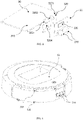
- FIG. 6 illustrates the housing 50 of the mobile robot 1 according to some exemplary embodiments of the present disclosure.
- At least one hook may be arranged on an inner side of the anti-collision device 60, and at least one groove corresponding to the at least one hook is arranged on the housing 50.
- the at least one hook is engaged in the at least one groove, such that the anti-collision device 60 can move back and forth relative to the housing 50, and there is a gap with the camera module 210 when the anti-collision device 60 moves to a rear limit position.
- the anti-collision device 60 may be arranged being protruded from the camera module 210 along a traveling direction of the mobile robot, thereby preventing other objects from directly colliding with the camera module 210 in the process of the mobile robot advancing.
- the upper shell of the housing 50 is substantially circular
- the anti-collision device 60 is a ring segment covering at least the camera module 210.
- a plurality of upper hooks 610 are arranged on an upper side of the anti-collision device 60 and a plurality of lower hooks 620 are arranged on a lower side of the anti-collision device 60.
- Hook bodies of the plurality of upper hooks 610 respectively extend downward along an axial direction and are engaged in the groove 510 arranged in an upper side wall of the housing 50
- hook bodies of the plurality of lower hooks 620 respectively extend inward along a radial direction and are engaged in the groove 520 arranged in a circumferential side wall of the housing 50.
- the upper side surface of the anti-collision device 60 and the upper side surface of the housing 50 form a smooth surface
- the circumferential outer side of the anti-collision device 60 and the circumferential outer side of the housing 50 form a smooth surface
- the housing 50 is provided with a recess 530 at a circumferential position corresponding to the camera module 210, and the camera module 210 may protrude from the recess 530.
- the anti-collision device 60 is provided with a window 630 at a circumferential position corresponding to the recess 530.
- a transparent lens may be mounted on the window 630 to protect the camera module 210 while not blocking the line sight of the camera module 210. Moreover, the transparent lens can withstand a certain impact force when the mobile robot collides with other objects.
- the transparent lens may be an acrylic lens.
- the acrylic material may have good light transmittance and good mechanical property against impact.
- An inner edge and/or outer edge of the window 630 is chamfered to avoid blocking the view of the camera module 210.
Landscapes
- Engineering & Computer Science (AREA)
- Computer Vision & Pattern Recognition (AREA)
- Physics & Mathematics (AREA)
- General Physics & Mathematics (AREA)
- Multimedia (AREA)
- Aviation & Aerospace Engineering (AREA)
- Theoretical Computer Science (AREA)
- Electromagnetism (AREA)
- Signal Processing (AREA)
- Radar, Positioning & Navigation (AREA)
- Remote Sensing (AREA)
- Automation & Control Theory (AREA)
- Control Of Position, Course, Altitude, Or Attitude Of Moving Bodies (AREA)
- Electric Vacuum Cleaner (AREA)
- Studio Devices (AREA)
- Manipulator (AREA)
Description
- The present disclosure relates to the field of robots, and more particularly, to a mobile robot.
- There are technologies for obstacle avoidance and positioning related to mobile robots. In the related art, various types of devices are used to achieve positioning. The various types of devices may be, for example, a compass, an inertial navigation system, a global positioning system (GPS), a wheel odometer, etc. In actual situations, various challenges may be encountered when the above devices are used alone. Visual information has a wide acquisition range and is not subject to sliding of moving wheels, vision-based mobile robots have rapidly developed in recent years. In the related art, the vision-based mobile robot can acquire images of objects external to the mobile robot with a camera.
-
US 2019/0220033 A1 describes a moving robot comprising: a main body; a traveling unit configured to rotate and move the main body; a sensing unit configured to sense position information of a specific point of a front portion of a docking device; and a controller. The sensing unit comprises a 3D camera for sensing an image outside the moving robot and a light irradiation unit for irradiation light of a first pattern and light of a second pattern. The 3D camera acquires an image of the area to which light of the first pattern and the light of the second pattern are inputted. For example, the light of the first pattern and the light of the second pattern may be irradiated in a linear shape intersecting with each other, or may be irradiated in a horizontal straight line spaced up and down. - The method described in this section is not necessarily the method that has been conceived or adopted before. Unless otherwise stated, it should not be assumed that any method described in this section is considered as prior art merely by virtue of its inclusion in this section. Similarly, unless otherwise stated, the problems mentioned in this section should not be considered as recognized in any prior art.
- According to the present invention, a mobile robot is provided as set out in appended
claim 1. Advantageous embodiments of the present invention are described by the dependent claims. - The accompanying drawings herein are incorporated in and become parts of the specification, illustrate embodiments consistent with the disclosure and, together with the description, serve to explain the principles of the disclosure. The embodiments described herein are for illustrative purposes only, and do not limit the scope of the present disclosure. In the drawings, the same reference numerals refer to similar but not necessarily identical elements.
-
FIG. 1 illustrates a schematic diagram of a mobile robot according to some exemplary embodiments of the present disclosure; -
FIG. 2 illustrates a schematic diagram of a mobile robot with a housing removed according to some exemplary embodiments of the present disclosure; -
FIG. 3 illustrates a schematic diagram of a bracket for a main control chip and a camera module of a mobile robot according to some exemplary embodiments of the present disclosure; -
FIG. 4 illustrates a schematic diagram of a mobile robot with an anticollision device removed according to some exemplary embodiments of the present disclosure; -
FIG. 5 illustrates a schematic diagram of an anti-collision device of a mobile robot according to some exemplary embodiments of the present disclosure; and -
FIG. 6 illustrates a schematic diagram of a housing of a mobile robot according to some exemplary embodiments of the present disclosure. - In the present disclosure, unless otherwise stated, terms such as "first" and "second", are used herein for differentiating one element from another element, and are not intended to limit the positional relationship, timing relationship or importance relationship of the elements. In some examples, a first element and a second element may refer to the same instance of the element, and in some cases, the first element and the second element may refer to different instances, based on the contextual description.
- The terms used in the description of various embodiments of the present disclosure are for the purpose of describing a particular example only, and are not intended to limit the present disclosure. Unless the context clearly indicates otherwise, if the number of elements is not specifically limited, there may be one or more elements. Moreover, terms such as "and/or" as used herein are intended to cover any and all possible combinations of the listed clauses.
- In the present disclosure, "horizontal plane" refers to a twodimensional plane on which a mobile robot is configured to move.
- In the present disclosure, "feature object" refers to an object associated with performing obstacle avoidance and positioning of the mobile robot.
- In the present disclosure, "obstacle avoidance" refers to avoiding obstacles, such as processing and controlling so as not to collide with obstacles.
- In the present disclosure, "obstacle object" refers to the feature object that the mobile robot needs to avoid during movement, and "non obstacle object" refers to the feature object that the mobile robot does not need to avoid during movement.
- In order to achieve a certain accuracy of positioning, the mobile robot needs to obtain data including depth information of the feature object through multiple images with a certain parallax. It is known that the motion parallax observed by the camera in the field of view may be increased by tilting the camera at an angle above the horizontal plane. Generally, the mobile robot uses the feature object above the horizontal plane as a reference object for positioning. The feature object may be a static feature object at a certain height. In the indoor environment, the feature object may be, for example, a clock, a photo frame, various decorative pieces, wall-mounted air conditioners hung on the wall, or a lighting lamp, a central air conditioner mounted on the ceiling, etc. In other words, in the related art, the optical axis of the camera equipped with the mobile robot is generally arranged obliquely upward. In this case, during the movement of the mobile robot, the camera can only capture the feature object at a higher position (such as on the wall or ceiling), and cannot capture the feature object on the horizontal plane on which the mobile robot moves, such that obstacle avoidance cannot be achieved. In other words, in the related art, the mobile robot cannot perform obstacle avoidance and positioning simultaneously merely through the image captured by the camera. Therefore, in the related art, in order to perform obstacle avoidance during the movement, the mobile robot needs to perceive the feature object on the horizontal plane, such that an additional measurement unit (such as a distance measuring sensor) needs to be installed.
- Accordingly, the present disclosure provides a mobile robot. The optical axis of the camera of the mobile robot is arranged in a direction parallel to the horizontal plane, and the mobile robot performs positioning using binocular parallax, without having to perform positioning by increasing the motion parallax observed by the camera in the field of view by tilting the optical axis of the camera.
- Unlike the mobile robot in the related art in which the optical axis of the camera is arranged obliquely upward, the optical axis of the camera according to the present disclosure is arranged in the direction parallel to the horizontal plane. The mobile robot according to the present disclosure can thus simultaneously perform obstacle avoidance and positioning by using the image captured by the camera, such that there is no need to install the distance measuring sensor. In some embodiments, since the mobile robot according to the present disclosure may not be equipped with the distance measuring sensor, this reduces the cost of the mobile robot. According to some other embodiments, although obstacle avoidance and positioning are achieved by using the camera, an additional distance measuring sensor may also be arranged. In this case, the camera and the distance measuring sensor can participate in obstacle avoidance of the mobile robot, so as to further improve the accuracy of obstacle avoidance and positioning.
- In addition, in the related art, the distance measuring sensor with which the mobile robot is equipped may only measure the distance between the mobile robot and the feature object on the horizontal plane, and cannot determine whether the feature object is an obstacle object or a non obstacle object. The mobile robot according to the present disclosure can obtain the image of the feature object on the horizontal plane through the camera, such that it can further analyze whether the feature object is an obstacle object or a non obstacle object through image processing technology.
- Moreover, in the related art, the mobile robot performs positioning using the feature objects above the horizontal plane, the feature objects above the horizontal plane (such as a wall-mounted air conditioner, a lighting lamp, etc.) generally have fixed positions, which makes the mobile robot in the related art less adaptable to the changes in the external environment. The mobile robot according to the present disclosure performs obstacle avoidance and positioning using the feature objects on the horizontal plane. These feature objects on the horizontal plane include objects generally having fixed positions such as beds, sofas, etc., and also include objects whose positions often change such as people, animals, and paper scraps, etc. Thereby, the mobile robot according to the present disclosure is more adaptable to the changes in the external environment compared to the mobile robot in the related art, and has better performance on obstacle avoidance and positioning when the external environment of the mobile robot changes.
- The mobile robot according to the present disclosure will be described in detail below with reference to the drawings.
-
FIG. 1 and FIG. 2 illustrate amobile robot 1 according to some exemplary embodiments of the present disclosure. InFIG. 2 , in order to clearly illustrate the internal components of the mobile robot, thehousing 50 of the mobile robot is removed. - The
mobile robot 1 according to some exemplary embodiments of the present disclosure may include a driving mechanism (not shown) configured to drive the mobile robot to move; achassis 10 on which the driving mechanism is mounted; and acamera mainboard 20 on which acamera module 210 is provided. Thecamera module 210 is configured to obtain an external environment image and has at least twooptical axes Fig. 2 . Thecamera mainboard 20 is arranged on thechassis 10 such that each of the at least two optical axes is parallel to the horizontal plane. The line intersecting the at least two optical axes may be parallel to the horizontal plane or perpendicular to the horizontal plane. - In some embodiments, in contrast to
Fig. 2 , the at least two optical axes may not be parallel to each other or not positioned in the same horizontal plane. - Referring to
FIG. 1 , according to some embodiments, themobile robot 1 may be any type of mobile robot capable of moving indoors or outdoors, including but not limited to a sweeping mobile robot, a weeding mobile robot, a window cleaning mobile robot, a greeting mobile robot, etc. - According to some embodiments, the
mobile robot 1 may include ahousing 50. Thehousing 50 may be an external housing capable of protecting components of the mobile robot to prevent intrusions such as water, dust, etc. The housing may have any shape, such as a flat cylindrical shape as shown inFIG. 1 or a humanoid shape that simulates a human. - According to some embodiments, the driving mechanism may be any type of mechanism capable of driving the mobile robot to move, for example, to translate or to rotate. For example, the driving mechanism may be a motor. According to some embodiments, the motor or other type of driving mechanism may drive various components of the mobile robot to perform various operations. For example, the motor or other type of driving mechanism may drive the camera to perform telescopic movement or rotational movement.
- According to some embodiments, the
camera module 210 has at least two optical axes. According to some embodiments, based on each of the at least two optical axes, the corresponding image in the field of view of the camera may be obtained respectively. Since there is a distance between the at least two optical axes , at least two images with binocular parallax between each other may be obtained for the same feature object in the external environment of the mobile robot. The at least two images may be sent to a processor for obstacle avoidance and positioning. The principle of generating binocular parallax using the at least two optical axes is similar to that of using two lenses of a binocular camera. - The
camera module 210 may include any type of camera suitable for the mobile robot. According to some embodiments, the camera may be a camera with a wide-angle lens. The camera may include any number of lenses. According to some embodiments, the camera may be at least one of a binocular camera, a multi-view camera, and a monocular camera with at least one optical axis. - According to some embodiments, each of the at least two optical axes of the
camera module 210 is parallel to the horizontal plane. The camera having the at least two optical axes parallel to the horizontal plane may obtain optical information of the feature object on the horizontal plane. In other words, the mobile robot may "see" the feature object on the horizontal plane, thereby achieving obstacle avoidance during the movement. According to some embodiments, the camera may have a certain pitch angle of view, such that the feature object on the horizontal plane that the mobile robot can "see" may include not only the feature object that is in direct contact with the horizontal plane, but also other feature objects that are not in direct contact with the horizontal plane but within the angle of view of the camera. In other words, by using the camera with at least two optical axes parallel to the horizontal plane, all the feature objects in the three-dimensional space between the horizontal plane on which the mobile robot moves and the maximum viewing angle plane of the camera may be obtained. The maximum viewing angle plane of the camera may be associated with the maximum angle of view, the maximum viewing distance, the type (binocular or monocular), or number (one or more) of the camera. It should be noted that "each of the at least two optical axes parallel to the horizontal plane" described herein does not mean that the included angle between each of the at least two optical axes and the horizontal plane should be zero. The included angle may also have other angles approximate to zero, and this is generally caused by an inevitable error in the production process of the mobile robot. For example, under normal circumstances, the included angle between each of the at least two optical axes and the horizontal plane is between -5 degrees and +5 degrees. - According to some embodiments, each of the at least two optical axes may be parallel to each other. When each of the at least two optical axes is parallel to each other, at least two images with binocular parallax may be analyzed, and the depth information of the feature object may be calculated according to the principle of similar triangles. According to some embodiments, each of the at least two optical axes may have a preset angle with respect to each other. When each of the at least two optical axes is not parallel to each other, the obtained at least two images may also have an offset of the coordinate system in addition to the binocular parallax. In this case, coordinate transformation may be performed on at least one of the obtained at least two images, such that the transformed coordinate system of the at least one image is unified with the coordinate system of the remaining images, and the depth information of the feature object is calculated based on the binocular parallax between the at least two images of the coordinate system.
- A
measurement unit 220 together with thecamera module 210 may be arranged on thecamera mainboard 20. Themeasurement unit 220 may be at least one of a Lidar sensor, an ultrasonic sensor, an infrared sensor, an inertial measurement unit (IMU), a GPS, and a wheel odometer. According to some embodiments, themeasurement unit 220 and thecamera module 210 may be connected to the same processor. - In some embodiments, the
measurement unit 220 may be an IMU. The IMU is a device that measures a three-axis attitude angle (or angular rate) and acceleration of the object, and can be configured to measure the relative motion distance of the object and position the object. The IMU together with thecamera module 210 may be arranged on thecamera motherboard 20, such that the relative position of the IMU and thecamera module 210 remains unchanged, ensuring that the IMU and the camera module move synchronously. The IMU and thecamera module 210 may be in the same system time, such that the time stamp of the data obtained by the IMU and thecamera module 210 may be calibrated and aligned. Moreover, the calibration method from the coordinate system of the IMU to the coordinate system of thecamera module 210 may be susceptible to noise when the relative position of the two changes. By arranging the IMU and the camera module on thesame camera mainboard 20, the transformation and calibration between their coordinate systems may be avoided, and thereby reducing the effect of the noise. According to some embodiments, the inertial measurement unit IMU and thecamera module 210 may be connected to the same processor. - According to some embodiments, at least one or all of the at least two optical axes of the
camera module 210 may be about 3cm away from the ground. This is to meet the field of view (FOV) requirement of the camera, such that the camera can identify the surrounding environment. Thereby, the camera may not be arranged too high or too low, about 3cm away from the ground is the best. In other embodiments, the distance between the at least one or all of the at least two optical axes of thecamera module 210 and the ground is not limited to 3cm, and the distance may also be set to other values, as long as the FOV requirement of the camera can be met. - The
chassis 10 includes abracket 30 configured to fix thecamera mainboard 20. Themain control chip 40 of the mobile robot is also arranged on thebracket 30. On the one hand, thebracket 30 plays a role of fixing, such that thecamera module 210, themeasurement unit 220 and other components on thecamera mainboard 20 will not be deformed, and there will be no relative displacement during the movement of the mobile robot. On the other hand, since a lot of heat may be generated during use of the chip (such as the chip of the measurement unit, and the main control chip) and other components, thebracket 30 is be made of a material with sufficient mechanical strength and easy to dissipate heat, such as aluminum alloy profiles, thereby achieving a good heat dissipation effect while the fixing effect is provided. -
FIG. 3 schematically illustrates thebracket 30 for thecamera module 20 and themain control chip 40 of the mobile robot according to some exemplary embodiments of the present disclosure. Thebracket 30 includes ahorizontal portion 310 configured to arrange themain control chip 40 and avertical portion 320 connected with thehorizontal portion 310. Thecamera mainboard 20 is fixed to thevertical portion 320. Thevertical portion 320 of thebracket 30 may be in a grid shape to form a heat dissipation grid, thereby further improving the heat dissipation effect. For example, thevertical portion 320 may include multiplevertical bar portions lateral bar portion 3204, and be connected with thehorizontal portion 310 through one of the at least one lateral bar portion. In the embodiment shown inFIG. 2 , thevertical portion 320 includes three vertical bar portions and one lateral bar portion, forming a shape similar to "(a Chinese character)" rotated by 90 degrees.
- According to some embodiments, the
horizontal portion 310 of thebracket 30 may be integrally formed with thevertical portion 320, for example, manufactured integrally by a numerically-controlled machine. - According to some embodiments, the horizontal portion of the bracket may also be in a grid shape to improve the heat dissipation effect on the main control chip.
- According to some embodiments, the
camera mainboard 20 may be fixed to thevertical portion 320 of thebracket 30 through a threaded connection, such that thecamera mainboard 20 will not be deformed during the process of being fixed to thebracket 30, and there will be no relative displacement between themeasurement unit 220 and thecamera module 210. For example, in the embodiment shown inFIG. 3 , on thevertical portion 320 of thebracket 30, a threaded hole is provided in the lower left corner, the lower right corner, and the upper middle side (i.e., the upper portion of the vertical bar portion in the middle), respectively, and thecamera mainboard 20 is fixed to thevertical portion 320 of thebracket 30 by locking screws at the corners or in the middle. On the one hand, thecamera mainboard 20 may be reliably fixed. On the other hand, there will no deformation during the process of fixing thecamera mainboard 20 to thebracket 30, and the relative position of themeasurement unit 220 and thecamera module 210 will not be changed. - According to some embodiments, the overall size of the vertical portion of the
bracket 30 may be slightly larger than that of thecamera mainboard 20, so as to facilitate the fixing of thecamera mainboard 20 to the vertical portion of thebracket 30. Certainly, it is also conceivable that the overall size of the horizontal portion of the bracket may be slightly larger than that of the main control chip arranged thereon, so as to facilitate the installation of the main control chip on the horizontal portion of the bracket. - According to some embodiments, the
mobile robot 1 may further include ananti-collision device 60 arranged on a circumferential outer side of thehousing 50. As shown inFIG. 1 , theanti-collision device 60 may be arranged in front of the camera module of themobile robot 1 to prevent damage to the camera module due to collision. -
FIG. 4 illustrates amobile robot 1 according to some exemplary embodiments of the present disclosure, and theanti-collision device 60 is removed from themobile robot 1.FIG. 5 illustrates theanti-collision device 60 of themobile robot 1 according to some exemplary embodiments of the present disclosure, andFIG. 6 illustrates thehousing 50 of themobile robot 1 according to some exemplary embodiments of the present disclosure. - In the embodiments shown in
FIGS. 4 to 6 , at least one hook may be arranged on an inner side of theanti-collision device 60, and at least one groove corresponding to the at least one hook is arranged on thehousing 50. The at least one hook is engaged in the at least one groove, such that theanti-collision device 60 can move back and forth relative to thehousing 50, and there is a gap with thecamera module 210 when theanti-collision device 60 moves to a rear limit position. - The
anti-collision device 60 may be arranged being protruded from thecamera module 210 along a traveling direction of the mobile robot, thereby preventing other objects from directly colliding with thecamera module 210 in the process of the mobile robot advancing. In the embodiments shown inFIGS. 4 to 6 , the upper shell of thehousing 50 is substantially circular, and theanti-collision device 60 is a ring segment covering at least thecamera module 210. A plurality ofupper hooks 610 are arranged on an upper side of theanti-collision device 60 and a plurality oflower hooks 620 are arranged on a lower side of theanti-collision device 60. Hook bodies of the plurality ofupper hooks 610 respectively extend downward along an axial direction and are engaged in thegroove 510 arranged in an upper side wall of thehousing 50, and hook bodies of the plurality oflower hooks 620 respectively extend inward along a radial direction and are engaged in thegroove 520 arranged in a circumferential side wall of thehousing 50. - As shown in
FIG. 1 , when theanti-collision device 60 is mounted on thehousing 50, the upper side surface of theanti-collision device 60 and the upper side surface of thehousing 50 form a smooth surface, and the circumferential outer side of theanti-collision device 60 and the circumferential outer side of thehousing 50 form a smooth surface. - The
housing 50 is provided with arecess 530 at a circumferential position corresponding to thecamera module 210, and thecamera module 210 may protrude from therecess 530. Theanti-collision device 60 is provided with awindow 630 at a circumferential position corresponding to therecess 530. A transparent lens may be mounted on thewindow 630 to protect thecamera module 210 while not blocking the line sight of thecamera module 210. Moreover, the transparent lens can withstand a certain impact force when the mobile robot collides with other objects. For example, the transparent lens may be an acrylic lens. The acrylic material may have good light transmittance and good mechanical property against impact. - An inner edge and/or outer edge of the
window 630 is chamfered to avoid blocking the view of thecamera module 210.
Claims (11)
- A mobile robot (1), comprising:a driving mechanism configured to drive the mobile robot to move;a chassis (10), on which the driving mechanism is mounted; anda camera mainboard (20), on which a camera module (210) is provided, and the camera module (210) being configured to obtain an external environment image and having at least two optical axes;wherein the camera mainboard (20) is arranged on the chassis (10) such that each of the at least two optical axes is substantially parallel to a horizontal plane,characterised in that the chassis (10) comprises a bracket (30) made of a heatdissipating material, the bracket (30) comprising a horizontal portion (310) configured to arrange a main control chip (40) and a vertical portion (320) connected with the horizontal portion (310), and the camera mainboard (20) is fixed to the vertical portion (320).
- The mobile robot (1) of claim 1, further comprising:
a measurement unit (220) arranged on the camera mainboard (20). - The mobile robot (1) of claim 1 or 2, wherein the camera module (210) is at least one of a binocular module, a multi-view module, and a monocular module with at least two optical axes.
- The mobile robot (1) of claim 1, wherein the vertical portion (320) is in a grid shape.
- The mobile robot (1) of any one of the preceding claims, wherein the vertical portion (320) comprises a plurality of vertical bar portions and at least one lateral bar portion, and the vertical portion (320) is connected with the horizontal portion (310) through one of the at least one lateral bar portion.
- The mobile robot (1) of any one of the preceding claims, wherein the horizontal portion (310) is in a grid shape.
- The mobile robot (1) of any one of the preceding claims, wherein the mobile robot (1) further comprises:a housing (50); andan anti-collision device (60) arranged on a circumferential outer side of the housing (50);wherein, at least one hook is arranged in an inner side of the anticollision device (60), and at least one groove corresponding to the at least one hook is arranged on the housing (50), and the at least one hook is engaged in the at least one groove, such that the anti-collision device (60) can move back and forth relative to the housing (50), and there is a gap between the anti-collision device (60) and the camera module (210) when the anti-collision device (60) moves to a rear limit position.
- The mobile robot (1) of claim 7, wherein the at least one hook comprises a plurality of upper hooks (610) arranged on an upper side of the anti-collision device (60) and a plurality of lower hooks (620) arranged on a lower side of the anticollision device (60),
wherein hook bodies of the plurality of upper hooks (610) respectively extend downward along an axial direction with respect to the mobile robot and are engaged in a first groove (510) arranged in an upper side wall of the housing (50), and hook bodies of the plurality of lower hooks (620) respectively extend inward along a radial direction with respect to the mobile robot and are engaged in a second groove (520) arranged in a circumferential side wall of the housing (50). - The mobile robot (1) of claim 7 or 8, wherein the anti-collision device (60) is arranged being protruded from the camera module (210) in a traveling direction of the mobile robot (1).
- The mobile robot (1) of any one of claims 7 to 9, wherein the housing (60) is provided with a recess (530) at a circumferential position corresponding to the camera module (210), and the anti-collision device (60) is provided with a window (630) at a circumferential position corresponding to the recess (530), and a transparent lens is mounted on the window (630).
- The mobile robot (1) of claim 10, wherein an inner edge and/or outer edge of the window (630) is chamfered.
Applications Claiming Priority (1)
| Application Number | Priority Date | Filing Date | Title |
|---|---|---|---|
| CN201921943519.8U CN210998737U (en) | 2019-11-12 | 2019-11-12 | Mobile robot |
Publications (2)
| Publication Number | Publication Date |
|---|---|
| EP3821780A1 EP3821780A1 (en) | 2021-05-19 |
| EP3821780B1 true EP3821780B1 (en) | 2022-05-25 |
Family
ID=71502174
Family Applications (1)
| Application Number | Title | Priority Date | Filing Date |
|---|---|---|---|
| EP20202475.8A Active EP3821780B1 (en) | 2019-11-12 | 2020-10-19 | Mobile robot |
Country Status (4)
| Country | Link |
|---|---|
| EP (1) | EP3821780B1 (en) |
| JP (1) | JP6906821B6 (en) |
| CN (1) | CN210998737U (en) |
| WO (1) | WO2021093392A1 (en) |
Families Citing this family (5)
| Publication number | Priority date | Publication date | Assignee | Title |
|---|---|---|---|---|
| KR102743768B1 (en) | 2019-11-12 | 2024-12-18 | 넥스트브이피유 (상하이) 코포레이트 리미티드 | Mobile robot |
| CN210998737U (en) * | 2019-11-12 | 2020-07-14 | 上海肇观电子科技有限公司 | Mobile robot |
| CN111887769A (en) * | 2020-08-27 | 2020-11-06 | 苏州三六零机器人科技有限公司 | Image sensing assembly, image sensing device and sweeper |
| JP2024525951A (en) * | 2021-07-23 | 2024-07-12 | アルフレッド ケルヒャー エスエー ウント コンパニー カーゲー | Self-propelled, self-steering floor cleaning device and floor cleaning system |
| CN113848964B (en) * | 2021-09-08 | 2024-08-27 | 金华市浙工大创新联合研究院 | Non-parallel optical axis binocular distance measuring method |
Family Cites Families (23)
| Publication number | Priority date | Publication date | Assignee | Title |
|---|---|---|---|---|
| JP2003280740A (en) * | 2002-03-25 | 2003-10-02 | Matsushita Electric Ind Co Ltd | Moving equipment |
| JP2005296510A (en) * | 2004-04-15 | 2005-10-27 | Funai Electric Co Ltd | Self-traveling vacuum cleaner with monitor camera |
| JP5105596B2 (en) * | 2007-10-30 | 2012-12-26 | 株式会社Ihi | Travel route determination map creation device and travel route determination map creation method for autonomous mobile body |
| US8229595B2 (en) * | 2008-06-19 | 2012-07-24 | Seelinger Michael J | Method and system for providing autonomous control of a platform |
| JP2011018150A (en) * | 2009-07-08 | 2011-01-27 | Toyota Auto Body Co Ltd | Unmanned traveling system |
| US9483055B2 (en) * | 2012-12-28 | 2016-11-01 | Irobot Corporation | Autonomous coverage robot |
| JP2016042285A (en) * | 2014-08-18 | 2016-03-31 | 株式会社東芝 | Autonomous mobile |
| US9519289B2 (en) * | 2014-11-26 | 2016-12-13 | Irobot Corporation | Systems and methods for performing simultaneous localization and mapping using machine vision systems |
| EP3761266A1 (en) * | 2016-07-12 | 2021-01-06 | SZ DJI Technology Co., Ltd. | Processing images to obtain environmental information |
| JP6850107B2 (en) * | 2016-11-02 | 2021-03-31 | 東芝ライフスタイル株式会社 | Autonomous electric cleaner |
| JP6831213B2 (en) * | 2016-11-09 | 2021-02-17 | 東芝ライフスタイル株式会社 | Vacuum cleaner |
| JP6837319B2 (en) * | 2016-11-18 | 2021-03-03 | 日立グローバルライフソリューションズ株式会社 | Self-propelled vacuum cleaner |
| CN106826749B (en) * | 2017-01-22 | 2024-01-26 | 深圳飞鼠动力科技有限公司 | Mobile robot |
| JP7042031B2 (en) * | 2017-03-17 | 2022-03-25 | 日立グローバルライフソリューションズ株式会社 | A system having an autonomous driving type vacuum cleaner and an autonomous traveling type vacuum cleaner and a charging stand. |
| CN109213137A (en) * | 2017-07-05 | 2019-01-15 | 广东宝乐机器人股份有限公司 | sweeping robot, sweeping robot system and its working method |
| CN208179600U (en) * | 2017-12-29 | 2018-12-04 | 杭州萤石软件有限公司 | Mobile robot |
| KR102203439B1 (en) * | 2018-01-17 | 2021-01-14 | 엘지전자 주식회사 | a Moving robot and Controlling method for the moving robot |
| CN108323238A (en) * | 2018-01-23 | 2018-07-24 | 深圳前海达闼云端智能科技有限公司 | Multi-eye camera system, terminal equipment and robot |
| JP7149502B2 (en) * | 2018-03-29 | 2022-10-07 | パナソニックIpマネジメント株式会社 | AUTONOMOUS MOBILE VACUUM CLEANER, CLEANING METHOD USING AUTONOMOUS MOBILE VACUUM CLEANER, AND PROGRAM FOR AUTONOMOUS MOBILE VACUUM CLEANER |
| CN209063102U (en) * | 2018-08-24 | 2019-07-05 | 科沃斯机器人股份有限公司 | Self-movement robot |
| CN209593641U (en) * | 2019-05-13 | 2019-11-05 | 广东宝乐机器人股份有限公司 | Camera module, binocular camera module and mobile robot |
| CN110123215A (en) * | 2019-06-20 | 2019-08-16 | 小狗电器互联网科技(北京)股份有限公司 | Sweeping robot |
| CN210998737U (en) * | 2019-11-12 | 2020-07-14 | 上海肇观电子科技有限公司 | Mobile robot |
-
2019
- 2019-11-12 CN CN201921943519.8U patent/CN210998737U/en active Active
-
2020
- 2020-08-14 WO PCT/CN2020/109338 patent/WO2021093392A1/en not_active Ceased
- 2020-10-19 EP EP20202475.8A patent/EP3821780B1/en active Active
- 2020-10-20 JP JP2020175989A patent/JP6906821B6/en active Active
Also Published As
| Publication number | Publication date |
|---|---|
| EP3821780A1 (en) | 2021-05-19 |
| JP6906821B2 (en) | 2021-07-21 |
| WO2021093392A1 (en) | 2021-05-20 |
| JP2021077361A (en) | 2021-05-20 |
| JP6906821B6 (en) | 2021-08-25 |
| CN210998737U (en) | 2020-07-14 |
Similar Documents
| Publication | Publication Date | Title |
|---|---|---|
| EP3821780B1 (en) | Mobile robot | |
| EP3776128B1 (en) | Apparatus, system, and method of using depth assessment for autonomous robot navigation | |
| Coombs et al. | Real-time obstacle avoidance using central flow divergence, and peripheral flow | |
| CN107235013B (en) | Vehicle navigation positioning panoramic cradle head | |
| US8224024B2 (en) | Tracking objects with markers | |
| CN108227699B (en) | Method for operating a vehicle with automatic forward motion | |
| US9992480B1 (en) | Apparatus and methods related to using mirrors to capture, by a camera of a robot, images that capture portions of an environment from multiple vantages | |
| US20120308114A1 (en) | Voting strategy for visual ego-motion from stereo | |
| CA2951170C (en) | Device for detecting an obstacle by means of intersecting planes and detection method using such a device | |
| CN113610910A (en) | Obstacle avoidance method for mobile robot | |
| US10869019B2 (en) | Dual depth camera module without blind spot | |
| US11054838B2 (en) | Mobile robot | |
| Kim et al. | Robotic wheelchair using a high accuracy visual marker lentibar and its application to door crossing navigation | |
| CN105856201B (en) | A kind of Robot Visual Servoing platform of Three Degree Of Freedom | |
| EP3885077B1 (en) | Robot sensor arrangement system | |
| CN108322698B (en) | System and method based on fusion of multiple cameras and inertial measurement unit | |
| EP3546882B1 (en) | Moving amount detection device | |
| CN217687537U (en) | Autonomous mobile human body temperature measuring equipment | |
| KR102853253B1 (en) | Non-oblique omnidirectional sensing mobile robot system equipped with multiple wide viewing angle lidar sensors | |
| KR20230016390A (en) | Wide viewing angle stereo camera apparatus and depth image processing method using the same | |
| CN110941288A (en) | An automatic obstacle avoidance device and method for low-altitude aircraft | |
| Satoh et al. | Development of omni-directional stereo vision-based intelligent electric wheelchair | |
| CN210173576U (en) | Transfer robot with multiple structured light binocular IR cameras | |
| CN210173577U (en) | Sweeping robot with multiple structured light binocular IR cameras | |
| Carlon et al. | Visual gyroscope for omnidirectional cameras |
Legal Events
| Date | Code | Title | Description |
|---|---|---|---|
| PUAI | Public reference made under article 153(3) epc to a published international application that has entered the european phase |
Free format text: ORIGINAL CODE: 0009012 |
|
| STAA | Information on the status of an ep patent application or granted ep patent |
Free format text: STATUS: REQUEST FOR EXAMINATION WAS MADE |
|
| 17P | Request for examination filed |
Effective date: 20201019 |
|
| AK | Designated contracting states |
Kind code of ref document: A1 Designated state(s): AL AT BE BG CH CY CZ DE DK EE ES FI FR GB GR HR HU IE IS IT LI LT LU LV MC MK MT NL NO PL PT RO RS SE SI SK SM TR |
|
| STAA | Information on the status of an ep patent application or granted ep patent |
Free format text: STATUS: EXAMINATION IS IN PROGRESS |
|
| 17Q | First examination report despatched |
Effective date: 20210610 |
|
| GRAP | Despatch of communication of intention to grant a patent |
Free format text: ORIGINAL CODE: EPIDOSNIGR1 |
|
| STAA | Information on the status of an ep patent application or granted ep patent |
Free format text: STATUS: GRANT OF PATENT IS INTENDED |
|
| INTG | Intention to grant announced |
Effective date: 20211206 |
|
| GRAS | Grant fee paid |
Free format text: ORIGINAL CODE: EPIDOSNIGR3 |
|
| GRAA | (expected) grant |
Free format text: ORIGINAL CODE: 0009210 |
|
| STAA | Information on the status of an ep patent application or granted ep patent |
Free format text: STATUS: THE PATENT HAS BEEN GRANTED |
|
| AK | Designated contracting states |
Kind code of ref document: B1 Designated state(s): AL AT BE BG CH CY CZ DE DK EE ES FI FR GB GR HR HU IE IS IT LI LT LU LV MC MK MT NL NO PL PT RO RS SE SI SK SM TR |
|
| REG | Reference to a national code |
Ref country code: GB Ref legal event code: FG4D |
|
| REG | Reference to a national code |
Ref country code: CH Ref legal event code: EP |
|
| REG | Reference to a national code |
Ref country code: DE Ref legal event code: R096 Ref document number: 602020003289 Country of ref document: DE |
|
| REG | Reference to a national code |
Ref country code: AT Ref legal event code: REF Ref document number: 1493924 Country of ref document: AT Kind code of ref document: T Effective date: 20220615 |
|
| REG | Reference to a national code |
Ref country code: IE Ref legal event code: FG4D |
|
| REG | Reference to a national code |
Ref country code: LT Ref legal event code: MG9D |
|
| REG | Reference to a national code |
Ref country code: NL Ref legal event code: MP Effective date: 20220525 |
|
| REG | Reference to a national code |
Ref country code: AT Ref legal event code: MK05 Ref document number: 1493924 Country of ref document: AT Kind code of ref document: T Effective date: 20220525 |
|
| PG25 | Lapsed in a contracting state [announced via postgrant information from national office to epo] |
Ref country code: SE Free format text: LAPSE BECAUSE OF FAILURE TO SUBMIT A TRANSLATION OF THE DESCRIPTION OR TO PAY THE FEE WITHIN THE PRESCRIBED TIME-LIMIT Effective date: 20220525 Ref country code: PT Free format text: LAPSE BECAUSE OF FAILURE TO SUBMIT A TRANSLATION OF THE DESCRIPTION OR TO PAY THE FEE WITHIN THE PRESCRIBED TIME-LIMIT Effective date: 20220926 Ref country code: NO Free format text: LAPSE BECAUSE OF FAILURE TO SUBMIT A TRANSLATION OF THE DESCRIPTION OR TO PAY THE FEE WITHIN THE PRESCRIBED TIME-LIMIT Effective date: 20220825 Ref country code: NL Free format text: LAPSE BECAUSE OF FAILURE TO SUBMIT A TRANSLATION OF THE DESCRIPTION OR TO PAY THE FEE WITHIN THE PRESCRIBED TIME-LIMIT Effective date: 20220525 Ref country code: LT Free format text: LAPSE BECAUSE OF FAILURE TO SUBMIT A TRANSLATION OF THE DESCRIPTION OR TO PAY THE FEE WITHIN THE PRESCRIBED TIME-LIMIT Effective date: 20220525 Ref country code: HR Free format text: LAPSE BECAUSE OF FAILURE TO SUBMIT A TRANSLATION OF THE DESCRIPTION OR TO PAY THE FEE WITHIN THE PRESCRIBED TIME-LIMIT Effective date: 20220525 Ref country code: GR Free format text: LAPSE BECAUSE OF FAILURE TO SUBMIT A TRANSLATION OF THE DESCRIPTION OR TO PAY THE FEE WITHIN THE PRESCRIBED TIME-LIMIT Effective date: 20220826 Ref country code: FI Free format text: LAPSE BECAUSE OF FAILURE TO SUBMIT A TRANSLATION OF THE DESCRIPTION OR TO PAY THE FEE WITHIN THE PRESCRIBED TIME-LIMIT Effective date: 20220525 Ref country code: BG Free format text: LAPSE BECAUSE OF FAILURE TO SUBMIT A TRANSLATION OF THE DESCRIPTION OR TO PAY THE FEE WITHIN THE PRESCRIBED TIME-LIMIT Effective date: 20220825 Ref country code: AT Free format text: LAPSE BECAUSE OF FAILURE TO SUBMIT A TRANSLATION OF THE DESCRIPTION OR TO PAY THE FEE WITHIN THE PRESCRIBED TIME-LIMIT Effective date: 20220525 |
|
| PG25 | Lapsed in a contracting state [announced via postgrant information from national office to epo] |
Ref country code: RS Free format text: LAPSE BECAUSE OF FAILURE TO SUBMIT A TRANSLATION OF THE DESCRIPTION OR TO PAY THE FEE WITHIN THE PRESCRIBED TIME-LIMIT Effective date: 20220525 Ref country code: PL Free format text: LAPSE BECAUSE OF FAILURE TO SUBMIT A TRANSLATION OF THE DESCRIPTION OR TO PAY THE FEE WITHIN THE PRESCRIBED TIME-LIMIT Effective date: 20220525 Ref country code: LV Free format text: LAPSE BECAUSE OF FAILURE TO SUBMIT A TRANSLATION OF THE DESCRIPTION OR TO PAY THE FEE WITHIN THE PRESCRIBED TIME-LIMIT Effective date: 20220525 Ref country code: IS Free format text: LAPSE BECAUSE OF FAILURE TO SUBMIT A TRANSLATION OF THE DESCRIPTION OR TO PAY THE FEE WITHIN THE PRESCRIBED TIME-LIMIT Effective date: 20220925 |
|
| PG25 | Lapsed in a contracting state [announced via postgrant information from national office to epo] |
Ref country code: SM Free format text: LAPSE BECAUSE OF FAILURE TO SUBMIT A TRANSLATION OF THE DESCRIPTION OR TO PAY THE FEE WITHIN THE PRESCRIBED TIME-LIMIT Effective date: 20220525 Ref country code: SK Free format text: LAPSE BECAUSE OF FAILURE TO SUBMIT A TRANSLATION OF THE DESCRIPTION OR TO PAY THE FEE WITHIN THE PRESCRIBED TIME-LIMIT Effective date: 20220525 Ref country code: RO Free format text: LAPSE BECAUSE OF FAILURE TO SUBMIT A TRANSLATION OF THE DESCRIPTION OR TO PAY THE FEE WITHIN THE PRESCRIBED TIME-LIMIT Effective date: 20220525 Ref country code: ES Free format text: LAPSE BECAUSE OF FAILURE TO SUBMIT A TRANSLATION OF THE DESCRIPTION OR TO PAY THE FEE WITHIN THE PRESCRIBED TIME-LIMIT Effective date: 20220525 Ref country code: EE Free format text: LAPSE BECAUSE OF FAILURE TO SUBMIT A TRANSLATION OF THE DESCRIPTION OR TO PAY THE FEE WITHIN THE PRESCRIBED TIME-LIMIT Effective date: 20220525 Ref country code: DK Free format text: LAPSE BECAUSE OF FAILURE TO SUBMIT A TRANSLATION OF THE DESCRIPTION OR TO PAY THE FEE WITHIN THE PRESCRIBED TIME-LIMIT Effective date: 20220525 Ref country code: CZ Free format text: LAPSE BECAUSE OF FAILURE TO SUBMIT A TRANSLATION OF THE DESCRIPTION OR TO PAY THE FEE WITHIN THE PRESCRIBED TIME-LIMIT Effective date: 20220525 |
|
| REG | Reference to a national code |
Ref country code: DE Ref legal event code: R097 Ref document number: 602020003289 Country of ref document: DE |
|
| PG25 | Lapsed in a contracting state [announced via postgrant information from national office to epo] |
Ref country code: AL Free format text: LAPSE BECAUSE OF FAILURE TO SUBMIT A TRANSLATION OF THE DESCRIPTION OR TO PAY THE FEE WITHIN THE PRESCRIBED TIME-LIMIT Effective date: 20220525 |
|
| PLBE | No opposition filed within time limit |
Free format text: ORIGINAL CODE: 0009261 |
|
| STAA | Information on the status of an ep patent application or granted ep patent |
Free format text: STATUS: NO OPPOSITION FILED WITHIN TIME LIMIT |
|
| 26N | No opposition filed |
Effective date: 20230228 |
|
| PG25 | Lapsed in a contracting state [announced via postgrant information from national office to epo] |
Ref country code: SI Free format text: LAPSE BECAUSE OF FAILURE TO SUBMIT A TRANSLATION OF THE DESCRIPTION OR TO PAY THE FEE WITHIN THE PRESCRIBED TIME-LIMIT Effective date: 20220525 Ref country code: MC Free format text: LAPSE BECAUSE OF FAILURE TO SUBMIT A TRANSLATION OF THE DESCRIPTION OR TO PAY THE FEE WITHIN THE PRESCRIBED TIME-LIMIT Effective date: 20220525 |
|
| REG | Reference to a national code |
Ref country code: BE Ref legal event code: MM Effective date: 20221031 |
|
| PG25 | Lapsed in a contracting state [announced via postgrant information from national office to epo] |
Ref country code: LU Free format text: LAPSE BECAUSE OF NON-PAYMENT OF DUE FEES Effective date: 20221019 |
|
| PG25 | Lapsed in a contracting state [announced via postgrant information from national office to epo] |
Ref country code: BE Free format text: LAPSE BECAUSE OF NON-PAYMENT OF DUE FEES Effective date: 20221031 |
|
| PG25 | Lapsed in a contracting state [announced via postgrant information from national office to epo] |
Ref country code: IE Free format text: LAPSE BECAUSE OF NON-PAYMENT OF DUE FEES Effective date: 20221019 |
|
| PG25 | Lapsed in a contracting state [announced via postgrant information from national office to epo] |
Ref country code: IT Free format text: LAPSE BECAUSE OF FAILURE TO SUBMIT A TRANSLATION OF THE DESCRIPTION OR TO PAY THE FEE WITHIN THE PRESCRIBED TIME-LIMIT Effective date: 20220525 |
|
| PG25 | Lapsed in a contracting state [announced via postgrant information from national office to epo] |
Ref country code: CY Free format text: LAPSE BECAUSE OF FAILURE TO SUBMIT A TRANSLATION OF THE DESCRIPTION OR TO PAY THE FEE WITHIN THE PRESCRIBED TIME-LIMIT Effective date: 20220525 |
|
| PG25 | Lapsed in a contracting state [announced via postgrant information from national office to epo] |
Ref country code: MK Free format text: LAPSE BECAUSE OF FAILURE TO SUBMIT A TRANSLATION OF THE DESCRIPTION OR TO PAY THE FEE WITHIN THE PRESCRIBED TIME-LIMIT Effective date: 20220525 |
|
| REG | Reference to a national code |
Ref country code: CH Ref legal event code: PL |
|
| PG25 | Lapsed in a contracting state [announced via postgrant information from national office to epo] |
Ref country code: CH Free format text: LAPSE BECAUSE OF NON-PAYMENT OF DUE FEES Effective date: 20231031 |
|
| PG25 | Lapsed in a contracting state [announced via postgrant information from national office to epo] |
Ref country code: HU Free format text: LAPSE BECAUSE OF FAILURE TO SUBMIT A TRANSLATION OF THE DESCRIPTION OR TO PAY THE FEE WITHIN THE PRESCRIBED TIME-LIMIT; INVALID AB INITIO Effective date: 20201019 Ref country code: CH Free format text: LAPSE BECAUSE OF NON-PAYMENT OF DUE FEES Effective date: 20231031 |
|
| PG25 | Lapsed in a contracting state [announced via postgrant information from national office to epo] |
Ref country code: MT Free format text: LAPSE BECAUSE OF FAILURE TO SUBMIT A TRANSLATION OF THE DESCRIPTION OR TO PAY THE FEE WITHIN THE PRESCRIBED TIME-LIMIT Effective date: 20220525 |
|
| PG25 | Lapsed in a contracting state [announced via postgrant information from national office to epo] |
Ref country code: BG Free format text: LAPSE BECAUSE OF FAILURE TO SUBMIT A TRANSLATION OF THE DESCRIPTION OR TO PAY THE FEE WITHIN THE PRESCRIBED TIME-LIMIT Effective date: 20220525 |
|
| PG25 | Lapsed in a contracting state [announced via postgrant information from national office to epo] |
Ref country code: BG Free format text: LAPSE BECAUSE OF FAILURE TO SUBMIT A TRANSLATION OF THE DESCRIPTION OR TO PAY THE FEE WITHIN THE PRESCRIBED TIME-LIMIT Effective date: 20220525 |
|
| PGFP | Annual fee paid to national office [announced via postgrant information from national office to epo] |
Ref country code: GB Payment date: 20250926 Year of fee payment: 6 |
|
| PGFP | Annual fee paid to national office [announced via postgrant information from national office to epo] |
Ref country code: FR Payment date: 20250919 Year of fee payment: 6 |
|
| PG25 | Lapsed in a contracting state [announced via postgrant information from national office to epo] |
Ref country code: TR Free format text: LAPSE BECAUSE OF FAILURE TO SUBMIT A TRANSLATION OF THE DESCRIPTION OR TO PAY THE FEE WITHIN THE PRESCRIBED TIME-LIMIT Effective date: 20220525 |
|
| PGFP | Annual fee paid to national office [announced via postgrant information from national office to epo] |
Ref country code: DE Payment date: 20250919 Year of fee payment: 6 |