EP3821695A1 - Work vehicle - Google Patents
Work vehicle Download PDFInfo
- Publication number
- EP3821695A1 EP3821695A1 EP20178751.2A EP20178751A EP3821695A1 EP 3821695 A1 EP3821695 A1 EP 3821695A1 EP 20178751 A EP20178751 A EP 20178751A EP 3821695 A1 EP3821695 A1 EP 3821695A1
- Authority
- EP
- European Patent Office
- Prior art keywords
- coupler
- machine body
- implement
- holding portion
- attached
- Prior art date
- Legal status (The legal status is an assumption and is not a legal conclusion. Google has not performed a legal analysis and makes no representation as to the accuracy of the status listed.)
- Granted
Links
Images




Classifications
-
- A—HUMAN NECESSITIES
- A01—AGRICULTURE; FORESTRY; ANIMAL HUSBANDRY; HUNTING; TRAPPING; FISHING
- A01D—HARVESTING; MOWING
- A01D43/00—Mowers combined with apparatus performing additional operations while mowing
- A01D43/06—Mowers combined with apparatus performing additional operations while mowing with means for collecting, gathering or loading mown material
- A01D43/063—Mowers combined with apparatus performing additional operations while mowing with means for collecting, gathering or loading mown material in or into a container carried by the mower; Containers therefor
- A01D43/0635—Mowers combined with apparatus performing additional operations while mowing with means for collecting, gathering or loading mown material in or into a container carried by the mower; Containers therefor with emptying means
Definitions
- the worker can separate the implement side coupler from the machine body side coupler and detach the cap from the coupler holding portion of the machine body and then attach it to the implement side coupler and attach the machine body side coupler to the coupler holding portion of the machine body.
- the cap When the implement is attached to the machine body, the cap is attached to the coupler holing portion, thus preventing adhesion of water, dust or the like to the coupler holding portion. Therefore, it is possible to avoid attachment of the implement side (machine body side) coupler to the coupler holding portion to which water, dust or the like has adhered.
- a coupler holding portion capable of holding the implement side coupler or the machine body side coupler is provided in ether the implement or the machine body.
- the number of the couplers is reduced and accidental loss of the cap(s) can be prevented.
- the condition shown in Fig. 2 is a condition in which the grass collecting section 10 is detached from the riding grass mowing machine.
- the grass collecting section 10 is attached to the ROPS frame 8 (riding grass mowing machine).
- this cap 36 there are formed a body portion 36a having the same outer shape as the inner faces of the upper portion 29a, the side portions 29b and the lower portion 29c of the coupler 29 (see Fig. 8 ) of the machine body side harness 28, a longitudinally elongate protruding portion 36b provided at the lower face portion of the body portion 36a, protruding portions 36c provided at the opposed side portions of the protruding portion 36b, and a grip portion 36d provided at a rear portion of the body portion 36a, and this cap 36 is formed of synthetic resin.
- the direction of connection to the coupler 29 of the machine body side harness 28 by the coupler 31 of the implement side harness 30 is the left/right direction
- the direction of insertion to the coupler holding portion 35 by the coupler 31 of the implement side harness 30 is the front/rear direction
- the connecting direction (left/right direction) and the inserting direction (front/rear direction) being set different from and orthogonal to each other.
- the control valve unit 11 may be attached to the grass collecting section 10. With this arrangement, when the grass collecting section 10 is attached to or detached from the riding grass mowing machine, the control valve unit 11 too will be attached to or detached from the riding grass mowing machine.
- the connecting direction to the coupler 29 of the machine body side harness 28 by the coupler 31 of the implement side harness 31 may be set as the front/rear direction and the inserting direction to the coupler holding portion 35 by the coupler 31 of the implement side harness 30 may be set as the left/right direction.
- the coupler 29 of the machine body side harness 28 will be attached to the coupler holding portion 35 provided in the machine body frame 3 or the ROPS frame 8 of the riding grass mowing machine and the cap 36 will be attached to the coupler 31 of the implement side harness 30.
Landscapes
- Life Sciences & Earth Sciences (AREA)
- Environmental Sciences (AREA)
- Harvester Elements (AREA)
- Lifting Devices For Agricultural Implements (AREA)
Abstract
Description
- The present invention relates to a work vehicle having an implement attached to a machine (vehicle) body.
- As a riding grass mowing machine as an example of a work vehicle, as disclosed in
Patent Document 1, there is known one in which a grass collecting section (corresponding to an "implement") is supported to a rear portion of the machine body. In this, cut grass pieces cut by a mower mounted to the machine body are sent to the grass collecting section to be stored therein. And, at the time of e.g. a maintenance operation, the grass collecting section can be detached from the machine body. - Patent Document 1: Japanese Unexamined Patent Application Publication
2010-148403 - With such riding grass mowing machine, an electrical unit such as a fullness sensor for detecting fullness of the grass collecting section being full of grass (cut grass pieces) therein may sometimes be provided in this grass collecting section. And, a harness extended from the electrical unit is extended to the machine body to be connected to e.g. a control device provided in this machine body.
- In this case, if the grass collecting section is configured to be detachable from the machine body as described above, the harness extending between the grass collecting section and the machine body needs to be provided with a harness separation arrangement using a coupler. So, consideration should be made on the water resistance and dust resistance properties of the coupler when separated.
- For such work vehicle having an implement configured to be attachable to and detachable from a machine body, the object of the present invention is to appropriately configure the harness separation arrangement using a coupler in case the harness is provided between the implement and the machine body.
- A work vehicle according to the present invention comprises:
- an implement attachable to and detachable from a machine body;
- an implement side harness extended from an electrical unit provided in the implement;
- an implement side coupler connected to an end portion of the implement side harness;
- a machine body side harness extended from the machine body;
- an machine body side coupler connected to an end portion of the machine body side harness;
- a coupler holding portion provided in the implement or the machine body, the coupler holding portion being configured to hold and cover either the implement side coupler or the machine body side coupler in association with insertion thereto of the implement side coupler or the machine body side coupler; and
- a cap attached to the implement side coupler or the machine body side coupler, or attached to the coupler holding portion;
- wherein under a working state, the implement side coupler and the machine body side coupler are connected to each other and the cap is attached to the coupler holding portion; and
- wherein under a non-working state, the implement side coupler is attached to the coupler holding portion of the implement and the cap is attached to the machine body side coupler, or the machine body side coupler is attached to the coupler holding portion of the machine body and the cap is attached to the implement side coupler.
- With the present invention described above, under a condition of the implement being attached to the machine body, a worker will keep the implement side coupler and the machine body side coupler connected to each other.
- By attaching the cap which is used when the implement is detached from the machine body to the coupler holding portion, the worker will have not much trouble in storage of the cap and accidental loss of the cap will hardly occur. And, thanks to the cap, adhesion of water, dust or the like to the coupler holding portion can be prevented.
- When the implement is to be detached from the machine body, if e.g. the coupler holding portion is provided in the implement, the worker can simply separate the implement side coupler from the machine body side coupler and detach the cap from the coupler holding portion of the implement and then attach it to the machine body side coupler and attach the implement coupler to the coupler holding portion of the implement.
- On the other hand, when the implement is to be detached from the machine body, if e.g. the coupler holding portion is provided in the machine body, the worker can separate the implement side coupler from the machine body side coupler and detach the cap from the coupler holding portion of the machine body and then attach it to the implement side coupler and attach the machine body side coupler to the coupler holding portion of the machine body.
- With execution of the above-described operations, the implement can be smoothly and easily detached from the machine body.
- And, as the cap is attached to the machine body side (implement side) coupler, adhesion of water, dust or the like to the machine body side (implement side) coupler can be prevented.
- As the implement side (machine body side) coupler is attached to the coupler holding portion, adhesion of water, dust or the like to the implement side (machine body side) coupler can be prevented.
- When the implement is attached to the machine body, the cap is attached to the coupler holing portion, thus preventing adhesion of water, dust or the like to the coupler holding portion. Therefore, it is possible to avoid attachment of the implement side (machine body side) coupler to the coupler holding portion to which water, dust or the like has adhered.
- In contrast to the present invention described above, it is conceivable to arrange such that when the implement side coupler and the machine body side coupler were separated from each other, a cap is attached to the implement side coupler and another cap is attached to the machine body side coupler. With this arrangement, at least two caps are needed for the one set of implement side harness and the machine body side harness.
- On the other hand, in the case of the present invention, as described above, a coupler holding portion capable of holding the implement side coupler or the machine body side coupler is provided in ether the implement or the machine body. Thus, the number of the couplers is reduced and accidental loss of the cap(s) can be prevented.
- And, since the coupler holding portion has two functions, namely, a function of holding the implement side coupler or the machine body side coupler and another function of holding the cap. Thus, the inventive arrangement is advantageous for simplification of the arrangement.
- In the present invention, preferably, the coupler holding portion is provided in the implement and the non-working state can be set in which the implement side coupler is attached to the coupler holding portion of the implement and the cap is attached to the machine body side coupler.
- With the invention described above, the coupler holding portion is provided in the implement. When the implement is to be detached from the machine body, the worker will separate the implement side coupler from the machine body side coupler and detach the cap from the coupler holding portion and then attach it to the machine body side coupler and attach the implement side coupler to the coupler holding portion.
- With the present invention, in the implement which has been detached from the machine body, the implement side coupler is held by the coupler holding portion of the implement. Thus, the implement side harness can be supported to the implement in a stable manner.
- In case various kinds of implements are supposed to be attached to the machine body, according to the present invention, in comparison with an arrangement of the coupler holding portion being provided in the machine body, the coupler holding portion can be readily adapted for use with the implement, for such various kinds of implements respectively.
- In the present invention, preferably, the machine body side coupler is provided in a support member provided in the machine body.
- With the present invention described above, when the implement side coupler and the machine body side coupler have been separated from each other, since the machine body side coupler is attached to a support member provided in the machine body, the machine body side coupler can be supported to the machine body in a stable manner.
- In the present invention, preferably, when the implement is attached to the machine body, a connecting direction to the machine body side coupler by the implement side coupler is set different from an inserting direction to the coupler holding portion by the implement side coupler.
- In case the implement which was detached previously from the machine body has now been attached to the machine body, the worker will detach the implement side coupler from the coupler holding portion and then connect it to the machine body side coupler.
- In this case, under the condition of the implement being attached to the machine body, if the connecting direction to the machine body side coupler by the implement side coupler were set same as the inserting direction to the coupler holding portion by the implement side coupler, the worker might erroneously attach the implement side coupler to the coupler holding portion of the implement again, after once detaching this implement side coupler from the coupler holding portion of the implement.
- With the present invention described above, when the implement is attached to the machine body, the connecting direction to the machine body side coupler by the implement side coupler is set different from the inserting direction to the coupler holding portion by the implement side coupler.
- With the above, even if the worker may attempt an erroneous operation of reattaching the implement side coupler to the coupler holding portion of the implement after having detached the former from the latter, thanks to the difference set between the connecting direction and the inserting direction described above, the worker will readily take notice of the contemplated operation being erroneous. As a result, the erroneous operation of reattaching the implement side coupler to the coupler holding portion of the implement after having once detached the former from the latter can be lessened.
-
-
Fig.1 is a right side view showing a riding grass mowing machine under a condition of a grass collecting section and a control valve unit being attached to a machine body, -
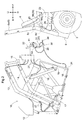
Fig.2 is a right side view showing a condition of the grass collecting section and the control valve unit being detached from the machine body, -
Fig. 3 is a front view showing vicinity of the control valve unit and a cover under a condition of the control valve unit being attached to the machine body, -
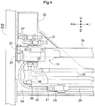
Fig. 4 is a front view showing vicinity of the control valve unit under the condition of the control valve unit being attached to the machine body, -
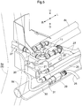
Fig.5 is a perspective view showing the vicinity of the control valve unit under the condition of the control valve unit being attached to the machine body, -
Fig. 6 is a perspective view showing the cover and a coupler holding portion, -
Fig. 7 is a perspective view showing the cover and the coupler holding portion, -
Fig. 8 is a perspective view showing a coupler of a machine body side harness, -
Fig. 9 is a perspective view showing a coupler of an implement side harness, and -
Fig. 10 is a perspective view of a cap. -
Figs. 1 through 10 show a mid-mount riding type grass mowing machine as one example of a "work vehicle". InFigs. 1 through 10 , a sign "F" denotes the front direction, a sign "B" denotes a rear (back) direction, a sign "U" denotes the upper direction, a sign "D" denotes the downward direction, a sign "R" denotes the right direction and a sign "L" denotes the left direction, respectively. - As shown in
Fig. 1 , right and leftfront wheels 1 and right and leftrear wheels 2 together support a machine body frame 3 (corresponding to a "machine body"), and amower 4 is disposed between thefront wheels 1 and therear wheels 2 and supported to themachine body frame 3. - An
engine 5 is supported to a front portion of themachine body frame 3 and a driver'sseat 6 is supported to a rear portion of themachine body frame 3. At a position forwardly of the driver'sseat 6, there is supported asteering wheel 7 for steering thefront wheels 1. - As shown in
Figs. 1 through 4 , a ROPS frame 8 (corresponding also to the "machine body") is coupled to themachine body frame 3 to be disposed rearwardly of the driver'sseat 6 as seen in a side view. TheROPS frame 8 includes right and leftstruts 8a coupled to rear portions of themachine body frame 3 and extending upwards, anarch portion 8b connected to and between upper portions of the right and leftstruts 8a, and aside frame 8c and aside frame 8d (both corresponding to a "support member") coupled to and between vertically intermediate portions of the right and leftstruts 8a of theROPS frame 8. - From a left/right center portion of the
mower 4, aduct 9 is extended obliquely upwards on the rear side, and theduct 9 is disposed between the right and leftrear wheels 2 and between the right and leftstruts 8a of theROPS frame 8 and is disposed also downwardly of the driver'sseat 6. - A grass collecting section 10 (corresponding to an "implement") is provided to be attachable to and detachable from the right and left
struts 8a of theROPS frame 8. A control valve unit 11 (corresponding also to the "implement") for feeding/discharging work oil to/from agrass collecting section 10 is provided to be attachable to and detachable from theside frame 8c of theROPS frame 8. - As shown in
Figs. 1 and2 , thegrass collecting section 10 includes agrass collecting container 12, right and leftupper links 13, right and leftlower links 14, right and leftsupport brackets 15, right and lefthydraulic cylinders - The
grass collecting container 12 is configured as a box-like member, with attachment of a wall face constituted of such a member as an air-permeable mesh or the like having air permeability to a box-like frame. Thefullness sensor 18 is provided at a front lower portion inside thegrass collecting container 12 and configured to detect a movement of a movable contact plate (not shown). - Leading ends of the
upper links 13 and thelower links 14 are placed in contact with a right rear portion and a left rear portion of thegrass collecting container 12. Between and to base portions of the rightupper link 13 and the rightlower link 14, theright support bracket 15 is connected, and between and to base portions of the leftupper link 13 and the leftlower link 14, theleft support bracket 15 is connected. - The right and left
hydraulic cylinders 16 are connected to and between the right and leftlower links 14 and the right and leftsupport brackets 19 of thegrass collecting section 10. The right and lefthydraulic cylinders 17 are provided at the connecting portions between theupper links 14, thelower links 14 and thegrass collecting container 12. - The condition shown in
Fig. 2 is a condition in which thegrass collecting section 10 is detached from the riding grass mowing machine. As shown fromFig. 2 to Fig. 1 , as the right and leftsupport brackets 15 are coupled to the right and leftstruts 8a of theROPS frame 8, thegrass collecting section 10 is attached to the ROPS frame 8 (riding grass mowing machine). - Under the condition of the
grass collecting section 10 being attached to theROPS frame 8, the rear portion of theduct 9 will be inserted to a front portion of thegrass collecting container 12. When a grass cutting (mowing) work is carried out, grass pieces cut by themower 4 will be conveyed through theduct 9 to be charged into the grass collecting container. 12. - When the cut grass pieces cut by the
mower 4 are to be charged into thegrass collecting container 12, these grass pieces will firstly be deposited at a rear lower portion of the inside of thegrass collecting container 12. In association with progressive charging of the grass pieces, the position of the cut grass pieces inside thegrass collecting container 12 will move to the forward side. And, when the grass pieces inside thegrass collecting container 12 reach a position in contact with thefullness sensor 18, it is determined that thegrass collecting container 12 has reached fullness. - When the
hydraulic cylinders 16 are expanded from the state thereof shown inFig.1 , the upper andlower links grass collecting container 12, while kept under the posture thereof shown inFig. 1 , will be elevated. - Then, under this elevated state of the
grass collecting container 12, if thehydraulic cylinders 17 are expanded, thegrass collecting container 12 will be pivoted clockwise inFig. 1 , about the connecting portions with the upper andlower links grass collecting container 12 will be oriented downwards, thus allowing discharge (dumping) of the cut grass pieces of thegrass collecting container 12 onto the ground surface. - The
control valve unit 11 is provided with a plurality of electromagnetic control valves (corresponding to the "electrical unit") (not shown) for carrying out feeding/discharging operations of the work oil to/from thehydraulic cylinders - As shown in
Figs. 2 through 5 , the side frames 8c, 8d of theROPS frame 8 are located on the lateral sides of the driver'sseat 6 as seen in the side view and asupport bracket 20 is coupled and bound between theright strut 8a and the right end portion of theside frame 8c of theROPS frame 8. - The
control valve unit 11 is attached to thesupport bracket 20 via an attachingpin 21 and is attached to theROPS frame 8 via thesupport bracket 20. By detachment of the attachingpin 21 from thesupport bracket 20, thecontrol valve unit 11 is detached from theROPS frame 8. - As shown in
Fig. 1 andFig. 2 , under the condition of thecontrol valve unit 11 is attached to theROPS frame 8, thecontrol unit 11 is disposed at substantially same height as the seat portion of the driver'sseat 6 as seen in the side view and disposed also rearwardly of the seat portion of the driver'sseat 6 and is disposed on the right side of the driver'sseat 6 as seen in a front view (rear view) and is also disposed upwardly of afender 22 covering the upper side of the rightrear wheel 2. - A
cover 32 made of synthetic resin is provided and thiscover 32 is attached to a front portion of thecontrol valve unit 11 in such a manner as to cover the front face portion of thecontrol valve unit 11. - As shown in
Fig. 3 , asupport bracket 23 is coupled to an upper face portion of theduct 9 and feeding and discharginghydraulic hoses 24 are connected to thesupport bracket 23, and work oil of a hydraulic pump (not shown) driven by power of theengine 5 is fed to the feedinghydraulic hose 24. - As shown in
Figs. 2 through 5 , feeding and discharginghydraulic hoses 25 are extended from thecontrol valve unit 11 and thesehydraulic hoses 25 are connected to the respectivehydraulic hoses 24 viawork oil couplers 26. Further, a plurality ofhydraulic hoses 27 are extended from thecontrol valve unit 11 and thesehydraulic hoses 27 are connected to thehydraulic cylinders - With the above-described arrangements, in operation, the work oil of the hydraulic pump is fed/discharged via the
control valve unit 11 to/from thehydraulic cylinders hydraulic cylinders - As shown in
Figs. 3 ,4 and5 , a water-proof type machinebody side harness 28 is extended to theside frame 8d of theROPS frame 8 and a water-proof type coupler 29 is connected to an end portion of a machinebody side harness 28. Thecoupler 29 of themachine side harness 28 is attached to theside frame 8d of theROPS frame 8 to be disposed downwardly of thecontrol valve unit 11 as seen in the front view. - As shown in
Fig. 8 , in thecoupler 29 of the machinebody side harness 28, anupper portion 29a, two side (lateral)portions 29b and alower portion 29c are formed in continuation thus forming a cylindrical body. And, thiscoupler 29 of the machinebody side harness 28 is formed of synthetic resin. - At the
lower portion 29c of thecoupler 29 of the machinebody side harness 28, there is formed arecess portion 29d having a channel-like cross section and bulging downwards. And, at opposed ends of the entrance of thisrecess portion 29d, a pair of protrudingportions 29e are formed. - As shown in
Figs. 3 ,4 and5 , a water-proof type implementside harness 30 is extended from thecontrol valve unit 11 and a water-proof type coupler 31 is connected to the end portion of the implementside coupler 30. - As shown in
Fig. 9 , in thecoupler 31 of the implementside harness 30, there are formed abody portion 31a having a same outer shape as the inner faces of theupper portion 29a, theside portions 29b and thelower portion 29c of the coupler 29 (seeFig. 8 ) of the machinebody side harness 28, a longitudinally elongate protrudingportion 31b provided at the lower face portion of thebody portion 31a and protrudingportions 31c provided at opposed side (lateral) portions of the protrudingportion 31b, and thecoupler 31 of the implementside harness 30 is formed of synthetic resin. - As shown in
Figs. 5 ,8 and 9 , the implementside coupler 31 of the implementside harness 30 will be inserted into thecoupler 29 of the machinebody side harness 28 in such a manner that the protrudingportions coupler 31 of the implementside harness 30 are fitted into therecess portion 29d of thecoupler 29 of the machinebody side harness 28. With this, connection is established between thecoupler 31 of the implementside harness 30 and thecoupler 29 of the machinebody side harness 28. - In the course of the above process, the protruding
portion 31c of thecoupler 31 of the implementside harness 30 and the protrudingportion 29e of thecoupler 29 of the machinebody side harness 28 are elastically deformed and the protrudingportion 31c of thecoupler 31 of the implementside harness 30 rides over the protrudingportion 29e of thecoupler 29 of the machinebody side harness 28 and engagement is established between the protrudingportion 31c of thecoupler 31 of the implementside harness 30 and the protrudingportion 29e of thecoupler 29 of the machinebody side harness 28. With this, the connection between thecoupler 31 of the implementside harness 30 and thecoupler 29 of the machinebody side harness 28 is maintained. - As shown in
Fig. 2 , the implementside harness 30 is bifurcated into two branches, and a water-proof type coupler 33 is connected to an end portion of one branch of the implementside harness 30 and thiscoupler 33 is connected to thecontrol valve unit 11. And, a water-proof type coupler 34 is connected to an end portion of the other branch of the implementside harness 30 and thiscoupler 34 is connected to thefullness sensor 18. - With the above-described arrangements in operation, when a worker operates an operational tool (not shown) provided in the riding grass mowing machine, an operational signal of the operational tool is inputted to a control device (not shown), and an operational signal from this control device is outputted to the machine
body side harness 28. And, the operational signal of the control device is transmitted from the machinebody side harness 28 via the implementside harness 30 to thecontrol valve unit 11, whereby the control valves of thecontrol valve unit 11 are operated to expand/contract thehydraulic cylinders - When the
grass collecting container 12 becomes full of cut grass pieces, a detection signal is outputted from thefullness sensor 18 and this detection signal of thefullness sensor 18 is inputted from the implementside harness 30 via the machinebody side harness 28 to the control device. Then, based on this input of the detection signal of thefullness sensor 18, the control device activates an alarm lamp (not shown) or an alarm buzzer (not shown) to alert the worker. - As shown in
Fig. 6 andFig. 7 , in thecover 32 attached to the front portion of thecontrol valve unit 11, at a right end portion of the lower portion of the front face portion, acoupler holding portion 35 is formed integral with thecover 32. - In the
coupler holding portion 35, anupper portion 35a, two side (lateral)portions 35b and alower portion 35c are formed in continuation to form a cylindrical body and awall portion 35d is formed integrally at the inner depth portion of theupper portion 35a, theside portions 35b and thelower portion 35c. - At the
lower portion 35c of thecoupler holding portion 35, there is formed arecess portion 35e having a channel-like cross section and bulging downwards. And, at opposed ends of the entrance of thisrecess portion 35e, a pair of protrudingportions 35f are formed. With these,coupler holding portion 35 is provided with the same shape as that of thecoupler 29 of the machine body side harness 28 (seeFig. 8 ). - As shown in
Fig. 6 andFig. 10 , acap 36 is provided to be attachable to and detachable from thecoupler holding portion 35. - In this
cap 36, there are formed abody portion 36a having the same outer shape as the inner faces of theupper portion 29a, theside portions 29b and thelower portion 29c of the coupler 29 (seeFig. 8 ) of the machinebody side harness 28, a longitudinally elongate protrudingportion 36b provided at the lower face portion of thebody portion 36a, protrudingportions 36c provided at the opposed side portions of the protrudingportion 36b, and agrip portion 36d provided at a rear portion of thebody portion 36a, and thiscap 36 is formed of synthetic resin. - The
cap 36 is configured with the same shape as the coupler 31 (seeFig. 9 ) of the implementside harness 30, and thecap 36 differs from thecoupler 31 of the implementside harness 30 in that thecap 36 has no connecting terminal and thecap 36 has thegrip portion 36d. - As described above in the foregoing sections under the headings: (Attaching Operation of Grass Collecting Section to Riding Grass Mowing Machine and Grass Cutting Work) and (Arrangement of Control Valve Unit), under the condition of the
grass collecting section 10 and thecontrol valve unit 11 being attached to the riding grass mowing machine, there will arise a situation to be explained next. - As shown in
Fig. 1 andFigs. 3 through 6 , the worker will connect thecoupler 31 of the implementside harness 30 with thecoupler 29 of the machine body side harness 28 (see the forgoing section: (Arrangements of Implement Side Harness and Coupler)) and will attach thecap 36 to thecoupler holding portion 35 while holding thegrip portion 36d of thecap 36. - When the
cap 36 is to be attached to thecoupler holding portion 35, as shown inFig. 6 andFig. 10 , thecap 36 will be inserted into thecoupler holding portion 35 in such a manner that the protrudingportions cap 36 are fitted into therecess portion 35e of thecoupler holding portion 35. - In the course of the above, while the protruding
portion 36c of thecap 36 and the protrudingportion 35f of thecoupler holding portion 35 will be elastically deformed and the protrudingportion 36c of thecap 36 will ride over the protrudingportion 35f of thecoupler holding portion 35, thereby to establish connection between the protrudingportion 36c of thecap 36 and the protrudingportion 35f of thecoupler holding portion 35. With this, thecap 36 is held and retained to thecoupler holding portion 35. - The above-described situation is the working state.
- In this working state, as the
cap 36 is inserted to and held by thecoupler holding portion 35, thecap 36 is stored in thecoupler holding portion 35, so that intrusion or adhesion of water, dust, or the like to the interior of thecoupler holding portion 35 is prevented by thecap 36. - As described above in the foregoing sections under headings of: (Attaching Operation of Grass Collecting Section to Riding Grass Mowing Machine and Grass Cutting Work) and (Arrangement of Control Valve Unit), under the condition of the
grass collecting section 10 and thecontrol valve unit 11 being detached from the riding grass mowing machine, there will arise a situation to be explained next. - As shown in
Fig. 2 andFig. 6 , the worker will detach thecoupler 31 of the implementside harness 30 from thecoupler 29 of the machine body side harness 28 (see the foregoing section: (Arrangements of Implement Side Harness and Coupler). - The worker, while holding the
grip portion 36d of thecap 36, will detach thecap 36 from thecoupler holding portion 35 and then attach thiscap 36 to thecoupler 29 of the machinebody side harness 28. - Like the above case of the
cap 36 being attached to thecoupler holding portion 35, as shown inFig.8 and Fig. 10 , thecap 36 is inserted into thecoupler 29 of the machinebody side harness 28 in such a manner that the protrudingportions cap 36 are fitted into the recess portion 28d of thecoupler 29 of the machinebody side harness 29, thus establishing connection between the protrudingportion 36c of thecap 36 and the protrudingportion 29e of thecoupler 29 of the machinebody side harness 28. With this, thecap 36 is held and retained to thecoupler 29 of the machinebody side harness 28. - The worker will attach the
coupler 31 of the implementside harness 30 to thecoupler holding portion 35. - Like the above-described case of the
coupler 31 of the implementside harness 30 being attached to thecoupler 29 of the machinebody side harness 28, as shown inFig. 6 andFig. 9 , thecoupler 31 of the implementside harness 30 will be inserted into thecoupler holding portion 35 in such a manner that the protrudingportions coupler 31 of the implementside harness 30 are inserted into therecess portion 35e of thecoupler holding portion 35, thus establishing connection between the protrudingportion 31c of thecoupler 31 of the implementside harness 30 and the protrudingportion 35f of thecoupler holding portion 35. With this, thecoupler 31 of the implementside harness 30 is held and retained to thecoupler holding portion 35. - The above-described situation is the non-working state.
- In this non-working state, as the
cap 36 is stored in thecoupler 29 of the machinebody side harness 28. And, as thecap 36 is attached to thecoupler 29 of the machinebody side harness 28 in such as manner as to cover the connection terminal of thecoupler 29 of the machinebody side harness 28, intrusion and adhesion of water, dust or the like to thecoupler 29 of the machinebody side harness 28 can be prevented. - In the non-working state, as the
coupler 31 of the implementside harness 30 is inserted and attached to thecoupler holding portion 35, intrusion and adhesion of water, dust or the like to thecoupler 31 of the implementside harness 30 can be prevented. - In the working state, as the
cap 36 is attached to thecoupler holding portion 35, intrusion and adhesion of water, dust or the like to the interior of thecoupler holding portion 35 is prevented, so that the undesirable event of attachment of thecoupler 31 of the implementside harness 30 to thecoupler holding portion 35 to which water, dust or the like has adhered can be avoided advantageously. - As shown in
Figs. 3 through 6 , under the condition of thegrass collecting section 10 and thecontrol valve unit 11 being attached to the riding grass mowing machine, the direction of connection to thecoupler 29 of the machinebody side harness 28 by thecoupler 31 of the implementside harness 30 is the left/right direction, whereas the direction of insertion to thecoupler holding portion 35 by thecoupler 31 of the implementside harness 30 is the front/rear direction, thus, the connecting direction (left/right direction) and the inserting direction (front/rear direction) being set different from and orthogonal to each other. - The
control valve unit 11 may be attached to thegrass collecting section 10. With this arrangement, when thegrass collecting section 10 is attached to or detached from the riding grass mowing machine, thecontrol valve unit 11 too will be attached to or detached from the riding grass mowing machine. - As the implement
side harness 30, there may be employed an implementside harness 30 for a signal from a detection sensor (not shown) for detecting an expanded/contracted state of thehydraulic cylinders grass collecting section 10. - Under the condition of the
grass collecting section 10 and thecontrol valve unit 11 being attached to the riding grass mowing machine, the connecting direction to thecoupler 29 of the machinebody side harness 28 by thecoupler 31 of the implementside harness 31 may be set as the front/rear direction and the inserting direction to thecoupler holding portion 35 by thecoupler 31 of the implementside harness 30 may be set as the left/right direction. - The
coupler holding portion 35 may be provided in themachine body frame 3 or theROPS frame 8 of the riding grass mowing machine. - With this arrangement, in the working state, connection will be established between the
coupler 31 of the implementside harness 30 and thecoupler 29 of the machinebody side harness 28 and thecap 36 will be attached to thecoupler holding portion 35 provided in themachine body frame 3 or theROPS frame 8 of the riding grass mowing machine. - In the non-working state, the
coupler 29 of the machinebody side harness 28 will be attached to thecoupler holding portion 35 provided in themachine body frame 3 or theROPS frame 8 of the riding grass mowing machine and thecap 36 will be attached to thecoupler 31 of the implementside harness 30. - The present invention is applicable not only to a riding grass mowing machine, but also to any work vehicle with an implement other than the grass collecting section being configured to be attachable to and detachable from the machine (vehicle) body.
-
- 3:
- machine body frame (machine body)
- 8:
- ROPS frame (machine body)
- 8d:
- side frame (support member)
- 10:
- grass collecting section (implement)
- 11:
- control valve unit (implement)
- 18:
- fullness sensor (electrical unit)
- 28:
- machine body side harness
- 29:
- coupler
- 30:
- implement side harness
- 31:
- coupler
- 35:
- coupler holding portion
- 36:
- cap
Claims (4)
- A work vehicle comprising:an implement (10, 11) attachable to and detachable from a machine body (3, 8);an implement side harness (30) extended from an electrical unit (18) provided in the implement;an implement side coupler (31) connected to an end portion of the implement side harness;a machine body side harness (28) extended from the machine body;an machine body side coupler connected (29) to an end portion of the machine body side harness;a coupler holding portion (35) provided in the implement or the machine body, the coupler holding portion being configured to hold and cover either the implement side coupler or the machine body side coupler in association with insertion thereto of the implement side coupler or the machine body side coupler; anda cap (36) attached to the implement side coupler or the machine body side coupler, or attached to the coupler holding portion;wherein under a working state, the implement side coupler and the machine body side coupler are connected to each other and the cap is attached to the coupler holding portion; andwherein under a non-working state, the implement side coupler is attached to the coupler holding portion of the implement and the cap is attached to the machine body side coupler, or the machine body side coupler is attached to the coupler holding portion of the machine body and the cap is attached to the implement side coupler.
- The work vehicle of claim 1, wherein:the coupler holding portion (35) is provided in the implement; andthe non-working state can be set in which the implement side coupler (31) is attached to the coupler holding portion of the implement and the cap (36) is attached to the machine body side coupler (29).
- The work vehicle of claim 1 or 2, wherein the machine body side coupler (29) is provided in a support member (8d) provided in the machine body.
- The work vehicle of any of claims 1 to 3, wherein when the implement is attached to the machine body (3, 8), a connecting direction to the machine body side coupler (29) by the implement side coupler (31) is set different from an inserting direction to the coupler holding portion (35) by the implement side coupler.
Applications Claiming Priority (1)
| Application Number | Priority Date | Filing Date | Title |
|---|---|---|---|
| JP2019204873A JP7197459B2 (en) | 2019-11-12 | 2019-11-12 | work vehicle |
Publications (2)
| Publication Number | Publication Date |
|---|---|
| EP3821695A1 true EP3821695A1 (en) | 2021-05-19 |
| EP3821695B1 EP3821695B1 (en) | 2024-11-06 |
Family
ID=71069774
Family Applications (1)
| Application Number | Title | Priority Date | Filing Date |
|---|---|---|---|
| EP20178751.2A Active EP3821695B1 (en) | 2019-11-12 | 2020-06-08 | Work vehicle |
Country Status (2)
| Country | Link |
|---|---|
| EP (1) | EP3821695B1 (en) |
| JP (1) | JP7197459B2 (en) |
Citations (6)
| Publication number | Priority date | Publication date | Assignee | Title |
|---|---|---|---|---|
| FR2625643A1 (en) * | 1988-01-11 | 1989-07-13 | Textron Inc | FRAME FOR DEBRIS COLLECTOR AND COLLECTION ASSEMBLY |
| US6595737B1 (en) * | 2001-10-31 | 2003-07-22 | Frank Parish | Dischargeable hopper system for vehicular apparatus |
| JP2010148403A (en) | 2008-12-24 | 2010-07-08 | Kubota Corp | Grass collector of mower |
| JP2013013373A (en) * | 2011-07-05 | 2013-01-24 | Yanmar Co Ltd | Electric working vehicle |
| US20160316636A1 (en) * | 2015-04-28 | 2016-11-03 | Remark Technologies, Inc. | Lawn Sweeper |
| EP3097758A1 (en) * | 2015-05-27 | 2016-11-30 | Iseki & Co., Ltd. | Riding type lawn mower |
Family Cites Families (5)
| Publication number | Priority date | Publication date | Assignee | Title |
|---|---|---|---|---|
| JPH067585Y2 (en) * | 1988-11-09 | 1994-02-23 | 本田技研工業株式会社 | Wiring connection structure between towing vehicle and work implement |
| JP3157971B2 (en) * | 1993-12-08 | 2001-04-23 | 日立建機株式会社 | Work machine |
| JP2005168381A (en) * | 2003-12-10 | 2005-06-30 | Kubota Corp | Paddy field machine |
| ITBO20050642A1 (en) * | 2005-10-24 | 2007-04-25 | Ferri Srl | DEVICE AND METHOD OF CONTROL FOR THE MEANS OF SUPPORTING A TOOL |
| JP4778317B2 (en) * | 2006-01-20 | 2011-09-21 | 三菱農機株式会社 | Work vehicle |
-
2019
- 2019-11-12 JP JP2019204873A patent/JP7197459B2/en active Active
-
2020
- 2020-06-08 EP EP20178751.2A patent/EP3821695B1/en active Active
Patent Citations (6)
| Publication number | Priority date | Publication date | Assignee | Title |
|---|---|---|---|---|
| FR2625643A1 (en) * | 1988-01-11 | 1989-07-13 | Textron Inc | FRAME FOR DEBRIS COLLECTOR AND COLLECTION ASSEMBLY |
| US6595737B1 (en) * | 2001-10-31 | 2003-07-22 | Frank Parish | Dischargeable hopper system for vehicular apparatus |
| JP2010148403A (en) | 2008-12-24 | 2010-07-08 | Kubota Corp | Grass collector of mower |
| JP2013013373A (en) * | 2011-07-05 | 2013-01-24 | Yanmar Co Ltd | Electric working vehicle |
| US20160316636A1 (en) * | 2015-04-28 | 2016-11-03 | Remark Technologies, Inc. | Lawn Sweeper |
| EP3097758A1 (en) * | 2015-05-27 | 2016-11-30 | Iseki & Co., Ltd. | Riding type lawn mower |
Also Published As
| Publication number | Publication date |
|---|---|
| EP3821695B1 (en) | 2024-11-06 |
| JP2021073938A (en) | 2021-05-20 |
| JP7197459B2 (en) | 2022-12-27 |
Similar Documents
| Publication | Publication Date | Title |
|---|---|---|
| EP1232931A1 (en) | Automotive front body structure | |
| EP1795986A2 (en) | Route planning system for agricultural work machines | |
| US20190382980A1 (en) | System and method for aligning a carrier vehicle and a selectively attachable implement | |
| EP3821695B1 (en) | Work vehicle | |
| US11148518B2 (en) | Electric work vehicle arrangement | |
| AU6227180A (en) | Quick-coupling locking mechanism | |
| JP2010148403A (en) | Grass collector of mower | |
| AU663825B2 (en) | Working implement coupling apparatus | |
| US20160356016A1 (en) | Frame for supporting a radiator guard of a machine | |
| US9849854B2 (en) | Work vehicle | |
| AU2018301777B2 (en) | Guard assembly for truck body | |
| CA2351074C (en) | A skid steer loader frame | |
| EP3504951B1 (en) | Riding grass mower | |
| KR20180076280A (en) | Frame Apparatus of Agricultural Vehicle | |
| EP4027480A1 (en) | Stand for charger | |
| EP3878699B1 (en) | System for holding and storing disconnected lines | |
| US20130309056A1 (en) | Valve Mounting Structure for a Loader Work Vehicle, and a Loader Work Vehicle | |
| JP5226419B2 (en) | Loader working device | |
| JPH0343066Y2 (en) | ||
| US6530741B1 (en) | Self propelled vehicle with a loader | |
| EP3470262A1 (en) | Tractor | |
| KR200312761Y1 (en) | Coupler construction of the front loader for tractor adhere | |
| EP3764772B1 (en) | Material collecting equipment having collection basket releasably secured to handle via hook member | |
| US11280057B2 (en) | System and method for attaching implements to different skid steer mounts | |
| CA2159968C (en) | Protective member for a vehicle |
Legal Events
| Date | Code | Title | Description |
|---|---|---|---|
| PUAI | Public reference made under article 153(3) epc to a published international application that has entered the european phase |
Free format text: ORIGINAL CODE: 0009012 |
|
| STAA | Information on the status of an ep patent application or granted ep patent |
Free format text: STATUS: REQUEST FOR EXAMINATION WAS MADE |
|
| 17P | Request for examination filed |
Effective date: 20200608 |
|
| AK | Designated contracting states |
Kind code of ref document: A1 Designated state(s): AL AT BE BG CH CY CZ DE DK EE ES FI FR GB GR HR HU IE IS IT LI LT LU LV MC MK MT NL NO PL PT RO RS SE SI SK SM TR |
|
| GRAP | Despatch of communication of intention to grant a patent |
Free format text: ORIGINAL CODE: EPIDOSNIGR1 |
|
| STAA | Information on the status of an ep patent application or granted ep patent |
Free format text: STATUS: GRANT OF PATENT IS INTENDED |
|
| INTG | Intention to grant announced |
Effective date: 20240603 |
|
| GRAS | Grant fee paid |
Free format text: ORIGINAL CODE: EPIDOSNIGR3 |
|
| GRAA | (expected) grant |
Free format text: ORIGINAL CODE: 0009210 |
|
| STAA | Information on the status of an ep patent application or granted ep patent |
Free format text: STATUS: THE PATENT HAS BEEN GRANTED |
|
| AK | Designated contracting states |
Kind code of ref document: B1 Designated state(s): AL AT BE BG CH CY CZ DE DK EE ES FI FR GB GR HR HU IE IS IT LI LT LU LV MC MK MT NL NO PL PT RO RS SE SI SK SM TR |
|
| REG | Reference to a national code |
Ref country code: GB Ref legal event code: FG4D |
|
| REG | Reference to a national code |
Ref country code: CH Ref legal event code: EP |
|
| REG | Reference to a national code |
Ref country code: DE Ref legal event code: R096 Ref document number: 602020040674 Country of ref document: DE |
|
| REG | Reference to a national code |
Ref country code: IE Ref legal event code: FG4D |
|
| REG | Reference to a national code |
Ref country code: LT Ref legal event code: MG9D |
|
| REG | Reference to a national code |
Ref country code: NL Ref legal event code: MP Effective date: 20241106 |
|
| PG25 | Lapsed in a contracting state [announced via postgrant information from national office to epo] |
Ref country code: HR Free format text: LAPSE BECAUSE OF FAILURE TO SUBMIT A TRANSLATION OF THE DESCRIPTION OR TO PAY THE FEE WITHIN THE PRESCRIBED TIME-LIMIT Effective date: 20241106 Ref country code: PT Free format text: LAPSE BECAUSE OF FAILURE TO SUBMIT A TRANSLATION OF THE DESCRIPTION OR TO PAY THE FEE WITHIN THE PRESCRIBED TIME-LIMIT Effective date: 20250306 Ref country code: IS Free format text: LAPSE BECAUSE OF FAILURE TO SUBMIT A TRANSLATION OF THE DESCRIPTION OR TO PAY THE FEE WITHIN THE PRESCRIBED TIME-LIMIT Effective date: 20250306 |
|
| PG25 | Lapsed in a contracting state [announced via postgrant information from national office to epo] |
Ref country code: FI Free format text: LAPSE BECAUSE OF FAILURE TO SUBMIT A TRANSLATION OF THE DESCRIPTION OR TO PAY THE FEE WITHIN THE PRESCRIBED TIME-LIMIT Effective date: 20241106 Ref country code: NL Free format text: LAPSE BECAUSE OF FAILURE TO SUBMIT A TRANSLATION OF THE DESCRIPTION OR TO PAY THE FEE WITHIN THE PRESCRIBED TIME-LIMIT Effective date: 20241106 |
|
| REG | Reference to a national code |
Ref country code: AT Ref legal event code: MK05 Ref document number: 1738266 Country of ref document: AT Kind code of ref document: T Effective date: 20241106 |
|
| PG25 | Lapsed in a contracting state [announced via postgrant information from national office to epo] |
Ref country code: BG Free format text: LAPSE BECAUSE OF FAILURE TO SUBMIT A TRANSLATION OF THE DESCRIPTION OR TO PAY THE FEE WITHIN THE PRESCRIBED TIME-LIMIT Effective date: 20241106 |
|
| PG25 | Lapsed in a contracting state [announced via postgrant information from national office to epo] |
Ref country code: ES Free format text: LAPSE BECAUSE OF FAILURE TO SUBMIT A TRANSLATION OF THE DESCRIPTION OR TO PAY THE FEE WITHIN THE PRESCRIBED TIME-LIMIT Effective date: 20241106 |
|
| PG25 | Lapsed in a contracting state [announced via postgrant information from national office to epo] |
Ref country code: NO Free format text: LAPSE BECAUSE OF FAILURE TO SUBMIT A TRANSLATION OF THE DESCRIPTION OR TO PAY THE FEE WITHIN THE PRESCRIBED TIME-LIMIT Effective date: 20250206 |
|
| PG25 | Lapsed in a contracting state [announced via postgrant information from national office to epo] |
Ref country code: LV Free format text: LAPSE BECAUSE OF FAILURE TO SUBMIT A TRANSLATION OF THE DESCRIPTION OR TO PAY THE FEE WITHIN THE PRESCRIBED TIME-LIMIT Effective date: 20241106 Ref country code: GR Free format text: LAPSE BECAUSE OF FAILURE TO SUBMIT A TRANSLATION OF THE DESCRIPTION OR TO PAY THE FEE WITHIN THE PRESCRIBED TIME-LIMIT Effective date: 20250207 Ref country code: AT Free format text: LAPSE BECAUSE OF FAILURE TO SUBMIT A TRANSLATION OF THE DESCRIPTION OR TO PAY THE FEE WITHIN THE PRESCRIBED TIME-LIMIT Effective date: 20241106 |
|
| PG25 | Lapsed in a contracting state [announced via postgrant information from national office to epo] |
Ref country code: PL Free format text: LAPSE BECAUSE OF FAILURE TO SUBMIT A TRANSLATION OF THE DESCRIPTION OR TO PAY THE FEE WITHIN THE PRESCRIBED TIME-LIMIT Effective date: 20241106 |
|
| PG25 | Lapsed in a contracting state [announced via postgrant information from national office to epo] |
Ref country code: RS Free format text: LAPSE BECAUSE OF FAILURE TO SUBMIT A TRANSLATION OF THE DESCRIPTION OR TO PAY THE FEE WITHIN THE PRESCRIBED TIME-LIMIT Effective date: 20250206 |
|
| PG25 | Lapsed in a contracting state [announced via postgrant information from national office to epo] |
Ref country code: SM Free format text: LAPSE BECAUSE OF FAILURE TO SUBMIT A TRANSLATION OF THE DESCRIPTION OR TO PAY THE FEE WITHIN THE PRESCRIBED TIME-LIMIT Effective date: 20241106 |
|
| PGFP | Annual fee paid to national office [announced via postgrant information from national office to epo] |
Ref country code: DE Payment date: 20250429 Year of fee payment: 6 |
|
| PG25 | Lapsed in a contracting state [announced via postgrant information from national office to epo] |
Ref country code: DK Free format text: LAPSE BECAUSE OF FAILURE TO SUBMIT A TRANSLATION OF THE DESCRIPTION OR TO PAY THE FEE WITHIN THE PRESCRIBED TIME-LIMIT Effective date: 20241106 |
|
| PG25 | Lapsed in a contracting state [announced via postgrant information from national office to epo] |
Ref country code: EE Free format text: LAPSE BECAUSE OF FAILURE TO SUBMIT A TRANSLATION OF THE DESCRIPTION OR TO PAY THE FEE WITHIN THE PRESCRIBED TIME-LIMIT Effective date: 20241106 |
|
| PGFP | Annual fee paid to national office [announced via postgrant information from national office to epo] |
Ref country code: FR Payment date: 20250508 Year of fee payment: 6 |
|
| PG25 | Lapsed in a contracting state [announced via postgrant information from national office to epo] |
Ref country code: RO Free format text: LAPSE BECAUSE OF FAILURE TO SUBMIT A TRANSLATION OF THE DESCRIPTION OR TO PAY THE FEE WITHIN THE PRESCRIBED TIME-LIMIT Effective date: 20241106 |
|
| PG25 | Lapsed in a contracting state [announced via postgrant information from national office to epo] |
Ref country code: SK Free format text: LAPSE BECAUSE OF FAILURE TO SUBMIT A TRANSLATION OF THE DESCRIPTION OR TO PAY THE FEE WITHIN THE PRESCRIBED TIME-LIMIT Effective date: 20241106 |
|
| PG25 | Lapsed in a contracting state [announced via postgrant information from national office to epo] |
Ref country code: CZ Free format text: LAPSE BECAUSE OF FAILURE TO SUBMIT A TRANSLATION OF THE DESCRIPTION OR TO PAY THE FEE WITHIN THE PRESCRIBED TIME-LIMIT Effective date: 20241106 |
|
| PG25 | Lapsed in a contracting state [announced via postgrant information from national office to epo] |
Ref country code: IT Free format text: LAPSE BECAUSE OF FAILURE TO SUBMIT A TRANSLATION OF THE DESCRIPTION OR TO PAY THE FEE WITHIN THE PRESCRIBED TIME-LIMIT Effective date: 20241106 |
|
| REG | Reference to a national code |
Ref country code: DE Ref legal event code: R097 Ref document number: 602020040674 Country of ref document: DE |
|
| PG25 | Lapsed in a contracting state [announced via postgrant information from national office to epo] |
Ref country code: SE Free format text: LAPSE BECAUSE OF FAILURE TO SUBMIT A TRANSLATION OF THE DESCRIPTION OR TO PAY THE FEE WITHIN THE PRESCRIBED TIME-LIMIT Effective date: 20241106 |
|
| PLBE | No opposition filed within time limit |
Free format text: ORIGINAL CODE: 0009261 |
|
| STAA | Information on the status of an ep patent application or granted ep patent |
Free format text: STATUS: NO OPPOSITION FILED WITHIN TIME LIMIT |
|
| 26N | No opposition filed |
Effective date: 20250807 |
|
| REG | Reference to a national code |
Ref country code: CH Ref legal event code: H13 Free format text: ST27 STATUS EVENT CODE: U-0-0-H10-H13 (AS PROVIDED BY THE NATIONAL OFFICE) Effective date: 20260127 |
|
| PG25 | Lapsed in a contracting state [announced via postgrant information from national office to epo] |
Ref country code: MC Free format text: LAPSE BECAUSE OF FAILURE TO SUBMIT A TRANSLATION OF THE DESCRIPTION OR TO PAY THE FEE WITHIN THE PRESCRIBED TIME-LIMIT Effective date: 20241106 |
|
| PG25 | Lapsed in a contracting state [announced via postgrant information from national office to epo] |
Ref country code: LU Free format text: LAPSE BECAUSE OF NON-PAYMENT OF DUE FEES Effective date: 20250608 |
|
| GBPC | Gb: european patent ceased through non-payment of renewal fee |
Effective date: 20250608 |
|
| REG | Reference to a national code |
Ref country code: BE Ref legal event code: MM Effective date: 20250630 |
|
| PG25 | Lapsed in a contracting state [announced via postgrant information from national office to epo] |
Ref country code: GB Free format text: LAPSE BECAUSE OF NON-PAYMENT OF DUE FEES Effective date: 20250608 |
|
| PG25 | Lapsed in a contracting state [announced via postgrant information from national office to epo] |
Ref country code: IE Free format text: LAPSE BECAUSE OF NON-PAYMENT OF DUE FEES Effective date: 20250608 |
|
| PG25 | Lapsed in a contracting state [announced via postgrant information from national office to epo] |
Ref country code: BE Free format text: LAPSE BECAUSE OF NON-PAYMENT OF DUE FEES Effective date: 20250630 |
|
| PG25 | Lapsed in a contracting state [announced via postgrant information from national office to epo] |
Ref country code: CH Free format text: LAPSE BECAUSE OF NON-PAYMENT OF DUE FEES Effective date: 20250630 |