EP3821377B1 - Deep learning-based coregistration - Google Patents
Deep learning-based coregistration Download PDFInfo
- Publication number
- EP3821377B1 EP3821377B1 EP19852781.4A EP19852781A EP3821377B1 EP 3821377 B1 EP3821377 B1 EP 3821377B1 EP 19852781 A EP19852781 A EP 19852781A EP 3821377 B1 EP3821377 B1 EP 3821377B1
- Authority
- EP
- European Patent Office
- Prior art keywords
- machine learning
- image
- learning system
- images
- source
- Prior art date
- Legal status (The legal status is an assumption and is not a legal conclusion. Google has not performed a legal analysis and makes no representation as to the accuracy of the status listed.)
- Active
Links
Images



Classifications
-
- G—PHYSICS
- G06—COMPUTING OR CALCULATING; COUNTING
- G06T—IMAGE DATA PROCESSING OR GENERATION, IN GENERAL
- G06T7/00—Image analysis
- G06T7/30—Determination of transform parameters for the alignment of images, i.e. image registration
- G06T7/33—Determination of transform parameters for the alignment of images, i.e. image registration using feature-based methods
-
- G—PHYSICS
- G06—COMPUTING OR CALCULATING; COUNTING
- G06N—COMPUTING ARRANGEMENTS BASED ON SPECIFIC COMPUTATIONAL MODELS
- G06N3/00—Computing arrangements based on biological models
- G06N3/02—Neural networks
- G06N3/04—Architecture, e.g. interconnection topology
- G06N3/045—Combinations of networks
-
- G—PHYSICS
- G06—COMPUTING OR CALCULATING; COUNTING
- G06N—COMPUTING ARRANGEMENTS BASED ON SPECIFIC COMPUTATIONAL MODELS
- G06N3/00—Computing arrangements based on biological models
- G06N3/02—Neural networks
- G06N3/04—Architecture, e.g. interconnection topology
- G06N3/0464—Convolutional networks [CNN, ConvNet]
-
- G—PHYSICS
- G06—COMPUTING OR CALCULATING; COUNTING
- G06N—COMPUTING ARRANGEMENTS BASED ON SPECIFIC COMPUTATIONAL MODELS
- G06N3/00—Computing arrangements based on biological models
- G06N3/02—Neural networks
- G06N3/08—Learning methods
- G06N3/088—Non-supervised learning, e.g. competitive learning
-
- G—PHYSICS
- G06—COMPUTING OR CALCULATING; COUNTING
- G06T—IMAGE DATA PROCESSING OR GENERATION, IN GENERAL
- G06T3/00—Geometric image transformations in the plane of the image
- G06T3/02—Affine transformations
-
- G—PHYSICS
- G06—COMPUTING OR CALCULATING; COUNTING
- G06T—IMAGE DATA PROCESSING OR GENERATION, IN GENERAL
- G06T7/00—Image analysis
- G06T7/0002—Inspection of images, e.g. flaw detection
- G06T7/0012—Biomedical image inspection
-
- G—PHYSICS
- G06—COMPUTING OR CALCULATING; COUNTING
- G06N—COMPUTING ARRANGEMENTS BASED ON SPECIFIC COMPUTATIONAL MODELS
- G06N3/00—Computing arrangements based on biological models
- G06N3/02—Neural networks
- G06N3/04—Architecture, e.g. interconnection topology
- G06N3/048—Activation functions
-
- G—PHYSICS
- G06—COMPUTING OR CALCULATING; COUNTING
- G06T—IMAGE DATA PROCESSING OR GENERATION, IN GENERAL
- G06T2207/00—Indexing scheme for image analysis or image enhancement
- G06T2207/10—Image acquisition modality
- G06T2207/10072—Tomographic images
- G06T2207/10088—Magnetic resonance imaging [MRI]
-
- G—PHYSICS
- G06—COMPUTING OR CALCULATING; COUNTING
- G06T—IMAGE DATA PROCESSING OR GENERATION, IN GENERAL
- G06T2207/00—Indexing scheme for image analysis or image enhancement
- G06T2207/20—Special algorithmic details
- G06T2207/20081—Training; Learning
-
- G—PHYSICS
- G06—COMPUTING OR CALCULATING; COUNTING
- G06T—IMAGE DATA PROCESSING OR GENERATION, IN GENERAL
- G06T2207/00—Indexing scheme for image analysis or image enhancement
- G06T2207/20—Special algorithmic details
- G06T2207/20084—Artificial neural networks [ANN]
-
- G—PHYSICS
- G06—COMPUTING OR CALCULATING; COUNTING
- G06T—IMAGE DATA PROCESSING OR GENERATION, IN GENERAL
- G06T2207/00—Indexing scheme for image analysis or image enhancement
- G06T2207/30—Subject of image; Context of image processing
- G06T2207/30004—Biomedical image processing
- G06T2207/30048—Heart; Cardiac
Definitions
- Hu et al. in particular proposed a weakly supervised method for registering magnetic resonance (MR) images onto intraoperative transrectal ultrasound prostate images 6 . Their method learns both affine transformation for global alignment of one image onto another as well as dense deformation fields (DDFs) of one image onto another.
- MR magnetic resonance
- DDFs dense deformation fields
- CNNs convolutional neural networks
- DeformationNet takes a fully unsupervised approach to image coregistration.
- DeformationNet also explicitly stabilizes images or transfers contour masks across images.
- global alignment is learned via affine deformations in addition to the DDF, and an unsupervised loss function is maintained.
- the use of an unsupervised loss function obviates the need for explicit human-derived annotations on the data, which is advantageous since acquisition of those annotations is one of the major challenges for supervised and semi-supervised CNNs.
- DeformationNet is also unique in that, in at least some implementations, it applies an additional spatial transformation layer at the end of each transformation step, which provides the ability to "fine-tune" the previously predicted transformation so that the network might correct previous transformation errors.
- each pair of source and target images from a medical images database (101) represents two cardiac MR images from the same patient and possibly the same study.
- These cardiac MR series may include but are not limited to: Delayed Enhancement short axis (SAX) images, Perfusion SAX images, SSFP SAX images, T1/T2/T2* mapping SAX images, etc.
- An affine transformation matrix with N or more affine transformation parameters, where N is an integer greater than or equal to 0, is learned via a Global Network (104) wherein the input is a pair of images that includes a source image (103) and a target image (102).
- the learned affine transformation parameters are defined as those parameters which, when applied to the target image, align the target image with the source image.
- the target image is resized to match the size of the source image before the affine matrix is learned.
- the Global Network (104) is a regression network.
- a version of the Global Network (104) includes 32 initial convolutional filters. At least some implementations downsample using strides in the convolutional layers and there are 2 convolutional layers with kernel size 3, a batch normalization layer with a momentum rate, a dropout layer, and a ReLU nonlinearity layer before each downsampling operation.
- the last layer of the Global Network (104) is a dense layer mapping to the desired number of affine parameters.
- the affine parameter outputs of the Global Network (104) are used as input to another affine spatial transformation layer that is bounded by different scaling factors for rotation, scaling, and zooming.
- the scaling factors control the amount of affine deformations that can be made to the target image.
- the affine spatial transformation matrix output by the affine spatial transformation layer includes a regularization operation that is implemented in the form of a bending energy loss function.
- a gradient energy loss function for regularization of the affine spatial transformation matrix may also be used, for example. This regularization further prevents the learned affine spatial transformation matrix from generating unrealistically large transformations.
- a DDF is learned via a Local Network (106) wherein the input is a pair that includes a source image (102) and a target image (103).
- the target image (102) has first been warped onto the source image coordinates via an affine transformation matrix learned in the global network(104), providing a warped target image (105) to be input into the Local Network (106).
- the Local Network (106) is a neural network architecture that includes a downsampling path and then an upsampling path.
- a version of such Local Network includes 32 initial convolutional filters and skip connections between the corresponding downsampling and upsampling layers.
- At least some implementations downsample using strides in the convolutional layers and there are 2 convolutional layers with kernel size 3, a batch normalization layer with a momentum rate, a dropout layer, and a ReLU nonlinearity layer before each downsampling or upsampling operation. This upsampling allows the DDF to be the same size as the inputted source and target images provided that padding was used.
- the learned DDF output of the Local Network (106) goes through a freeform similarity spatial transformation layer.
- this freeform similarity spatial transformation layer can include affine transformations or dense freeform deformation field warpings 5 , or both. If affine transformations are used, they may be scaled to control the amount of deformations that can be made to the target images.
- the DDF also includes a regularization operation that is implemented in the form of a bending energy loss functions. A gradient energy loss function may also be used to regularize the DDF. This regularization prevents the learned DDF from generating deformations that are unrealistically large.
- the CNN models may be updated via backpropagation with an adam optimizer and a mutual information loss function between the source image and the target image that has been warped by the DDF (i.e., warped target image 105).
- Adam optimizer adjusts its learning rate through training using both the first and second moments of the backpropagated gradients.
- optimizers include stochastic gradient descent, minibatch gradient descent, adagrad, and root mean squared propagation.
- Other non-limiting examples of loss functions may include root mean squared error, L2 loss, L2 loss with center weighting, and cross correlation loss 7 between the source image and the DDF that has been applied to the target image. These loss functions only depend on the raw input data and what the DeformationNet learns from that raw data.
- the absence of any dependence on explicit hand-annotations allows for this system to be fully unsupervised.
- Weights of the trained Global Network (104) and Local Network (106) can be stored in storage devices including hard disks and solid state drives to be used later for image stabilization or segmentation mask transferring.
- Figure 2 illustrates an implementation of performing inference on a trained DeformationNet for image stabilization.
- the input to DeformationNet includes a source image (202), and a target image (203) to be stabilized by warping the target image onto the source image. These image pairings may be selected from a database of medical images (201).
- a DDF (205) with respect to the source image (202) is inferred.
- This DDF (205) is applied to the target image (203), creating a warped target image (206) that is stabilized with respect to the source image (202).
- the newly stabilized target image (206) may be displayed to the user via a display (207) and stored in a warped images database (209) including hard disks and solid state drives.
- a DDF (306) with respect to the source image is inferred.
- This DDF (306) is applied to the segmentation mask (304) corresponding to the target image (303) creating a warped segmentation mask (307) that has been warped onto the source image.
- the newly warped segmentation mask (307) can be displayed to the user via a display (308) and stored in a warped segmentation masks database (310) including but not limited to hard disks and solid state drives.
- Figure 4 illustrates one implementation of using a heuristic and previously trained CNN to select a segmentation mask to transfer to other images.
- a group of 2D cardiac SAX MR images (401) is chosen for which segmentations are needed.
- Those images (401) are used as input to a previously trained CNN (402), as discussed above.
- the CNN (402) was previously trained to segment masks for the LV epi, LV endo, and RV endo in 2D SSFP MRs images.
- the output of the CNN (402) is a segmentation probability map (403) on a per-pixel basis for each 2D image.
- Foreground and background maps for the images (504) and (510) are represented as contours in images (506) and (512), respectively.
- the black contours represent the foreground map values as calculated by act 1.b in the pseudocode above and the white contours represent the background map values as calculated by act 1.d in the pseudocode.
- Image (506) has high probability for the foreground map and background map, which would give it a high quality score.
- Image (510) has high probability for the background map but low for the foreground map, which would give it a low quality score and it would likely not be used as the segmentation mask to transfer across images.
- FIG. 6 shows a processor-based device 604 suitable for implementing the various functionality described herein.
- processor-executable instructions or logic such as program application modules, objects, or macros being executed by one or more processors.
- processors such as smartphones and tablet computers, wearable devices, multiprocessor systems, microprocessor-based or programmable consumer electronics, personal computers (“PCs"), network PCs, minicomputers, mainframe computers, and the like.
- PCs personal computers
- the processor-based device 604 may include one or more processors 606, a system memory 608 and a system bus 610 that couples various system components including the system memory 608 to the processor(s) 606.
- the processor-based device 604 will at times be referred to in the singular herein, but this is not intended to limit the implementations to a single system, since in certain implementations, there will be more than one system or other networked computing device involved.
- Non-limiting examples of commercially available systems include, but are not limited to, ARM processors from a variety of manufactures, Core microprocessors from Intel Corporation, U.S.A., PowerPC microprocessor from IBM, Sparc microprocessors from Sun Microsystems, Inc., PA-RISC series microprocessors from Hewlett-Packard Company, 68xxx series microprocessors from Motorola Corporation.
- the processor(s) 606 may be any logic processing unit, such as one or more central processing units (CPUs), microprocessors, digital signal processors (DSPs), application-specific integrated circuits (ASICs), field programmable gate arrays (FPGAs), etc. Unless described otherwise, the construction and operation of the various blocks shown in Figure 6 are of conventional design. As a result, such blocks need not be described in further detail herein, as they will be understood by those skilled in the relevant art.
- CPUs central processing units
- DSPs digital signal processors
- ASICs application-specific integrated circuits
- FPGAs field programmable gate arrays
- the system bus 610 can employ any known bus structures or architectures, including a memory bus with memory controller, a peripheral bus, and a local bus.
- the system memory 608 includes read-only memory (“ROM”) 1012 and random access memory (“RAM”) 614.
- ROM read-only memory
- RAM random access memory
- a basic input/output system (“BIOS”) 616 which can form part of the ROM 612, contains basic routines that help transfer information between elements within processor-based device 604, such as during start-up. Some implementations may employ separate buses for data, instructions and power.
- the processor-based device 604 may also include one or more solid state memories, for instance Flash memory or solid state drive (SSD) 618, which provides nonvolatile storage of computer-readable instructions, data structures, program modules and other data for the processor-based device 604.
- solid state memories for instance Flash memory or solid state drive (SSD) 618
- SSD solid state drive
- the processor-based device 604 can employ other nontransitory computer- or processor-readable media, for example a hard disk drive, an optical disk drive, or memory card media drive.
- Program modules can be stored in the system memory 608, such as an operating system 630, one or more application programs 632, other programs or modules 634, drivers 636 and program data 638.
- the panning / scrolling logic 632a may include processor and/or machine executable logic or instructions to generate user interface objects using data that characterizes movement of a pointer, for example data from a touch-sensitive display or from a computer mouse or trackball, or other user interface device.
- the system memory 608 may also include communications programs 640, for example a server and/or a Web client or browser for permitting the processor-based device 604 to access and exchange data with other systems such as user computing systems, Web sites on the Internet, corporate intranets, or other networks as described below.
- the communications programs 640 in the depicted implementation is markup language based, such as Hypertext Markup Language (HTML), Extensible Markup Language (XML) or Wireless Markup Language (WML), and operates with markup languages that use syntactically delimited characters added to the data of a document to represent the structure of the document.
- HTML Hypertext Markup Language
- XML Extensible Markup Language
- WML Wireless Markup Language
- a number of servers and/or Web clients or browsers are commercially available such as those from Mozilla Corporation of California and Microsoft of Washington.
- the operating system 630 can be stored on any other of a large variety of nontransitory processor-readable media (e.g., hard disk drive, optical disk drive, SSD and/or flash memory).
- nontransitory processor-readable media e.g., hard disk drive, optical disk drive, SSD and/or flash memory.
- a user can enter commands and information via a pointer, for example through input devices such as a touch screen 648 via a finger 644a, stylus 644b, or via a computer mouse or trackball 644c which controls a cursor.
- Other input devices can include a microphone, joystick, game pad, tablet, scanner, biometric scanning device, etc.
- I/O devices are connected to the processor(s) 606 through an interface 646 such as touch-screen controller and/or a universal serial bus (“USB”) interface that couples user input to the system bus 610, although other interfaces such as a parallel port, a game port or a wireless interface or a serial port may be used.
- the touch screen 648 can be coupled to the system bus 610 via a video interface 650, such as a video adapter to receive image data or image information for display via the touch screen 648.
- a video interface 650 such as a video adapter to receive image data or image information for display via the touch screen 648.
- the processor-based device 604 can include other output devices, such as speakers, vibrator, haptic actuator, etc.
- the processor-based device 604 may operate in a networked environment using one or more of the logical connections to communicate with one or more remote computers, servers and/or devices via one or more communications channels, for example, one or more networks 614a, 614b. These logical connections may facilitate any known method of permitting computers to communicate, such as through one or more LANs and/or WANs, such as the Internet, and/or cellular communications networks.
- Such networking environments are well known in wired and wireless enterprise-wide computer networks, intranets, extranets, the Internet, and other types of communication networks including telecommunications networks, cellular networks, paging networks, and other mobile networks.
- the processor-based device 604 may include one or more wired or wireless communications interfaces 614a, 614b (e.g., cellular radios, WI-FI radios, Bluetooth radios) for establishing communications over the network, for instance the Internet 614a or cellular network.
- wired or wireless communications interfaces 614a, 614b e.g., cellular radios, WI-FI radios, Bluetooth radios
- program modules, application programs, or data, or portions thereof can be stored in a server computing system (not shown).
- server computing system not shown.
- network connections shown in Figure 6 are only some examples of ways of establishing communications between computers, and other connections may be used, including wirelessly.
- processor(s) 606, system memory 608, network and communications interfaces 614a, 614b are illustrated as communicably coupled to each other via the system bus 610, thereby providing connectivity between the above-described components.
- the above-described components may be communicably coupled in a different manner than illustrated in Figure 6 .
- one or more of the above-described components may be directly coupled to other components, or may be coupled to each other, via intermediary components (not shown).
- system bus 610 is omitted and the components are coupled directly to each other using suitable connections.
Landscapes
- Engineering & Computer Science (AREA)
- Theoretical Computer Science (AREA)
- Physics & Mathematics (AREA)
- General Physics & Mathematics (AREA)
- General Health & Medical Sciences (AREA)
- Health & Medical Sciences (AREA)
- Computing Systems (AREA)
- Mathematical Physics (AREA)
- Data Mining & Analysis (AREA)
- Evolutionary Computation (AREA)
- Biophysics (AREA)
- Molecular Biology (AREA)
- Biomedical Technology (AREA)
- General Engineering & Computer Science (AREA)
- Artificial Intelligence (AREA)
- Computational Linguistics (AREA)
- Software Systems (AREA)
- Life Sciences & Earth Sciences (AREA)
- Computer Vision & Pattern Recognition (AREA)
- Medical Informatics (AREA)
- Nuclear Medicine, Radiotherapy & Molecular Imaging (AREA)
- Radiology & Medical Imaging (AREA)
- Quality & Reliability (AREA)
- Image Analysis (AREA)
Description
- Recently, deep learning has shown promising results in automating the segmentation of various medical images1,2. However, training of these deep learning algorithms requires large sets of training data from expert annotators. As such, using coregistration (spatial alignment) as a way to transfer one annotated mask or landmark across an entire image set is a valuable tool for reducing the number of manual labels required in a purely deep learning setting. Coregistration can also be used to spatially align annotated landmarks or masks from one image onto another and warp images into a common reference frame to ease manual or automated comparison.
- Traditional coregistration methods iteratively optimize an objective function on each new pair of images to be coregistered on, which is a computationally expensive process and can take hours to complete on a given image volume. Deep learning-based coregistration is capable of calculating the deformation without iteratively optimizing an objective function. When coupled with a graphics processing unit (GPU) as a processing unit, this results in a significantly reduced computational cost for computing the registration.
- Traditional coregistration methods calculate displacement vector fields across all image pairings through a variety of iterative methods such as elastic-type modeling3, statistical parametric mapping4, and free-form deformation with b-splines5.
- Frameworks for using deep convolutional neural networks (CNNs) to perform variants of coregistration on medical imaging are beginning to emerge. The majority of these methods are focused on creating deformation fields that minimize the difference between a pair of images. Hu et al. in particular proposed a weakly supervised method for registering magnetic resonance (MR) images onto intraoperative transrectal ultrasound prostate images6. Their method learns both affine transformation for global alignment of one image onto another as well as dense deformation fields (DDFs) of one image onto another. However, the method described in Hu et al. requires anatomical landmark points for training the model, the collection of which is time consuming and expensive. Balakrishnan et al. proposed a fully unsupervised CNN for coregistration of 3D MRI brain datasets where the loss function is purely based on the raw image data7. The approach of Balakrishnan et al. only learns the DDF of two images and accounts for affine transformations by feeding the DDF through a spatial transformation layer. SIYUAN SHAN ET AL: "Unsupervised End-to-end Learning for Deformable Medical Image Registration",ARXIV.ORG, CORNELL UNIVERSITY LIBRARY, 201, ITHACA, NY 14853, 23 November 2017, pertains to a machine learning system that receives learning data comprising a plurality of batches of unlabeled image sets, wherein each image set comprises a source image and target image that each represents a medical image scan of at least one patient; trains one or more convolutional neural networks (CNNs) models, based on the learning data, to learn one or more transformation functions between the plurality of unlabeled images that allow for coregistration of a target image onto a source image.
-
-
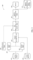
Figure 1 is a diagram of training a system of convolutional neural networks (CNNs), referred to herein as DeformationNet, to create a DDF to warp images for coregistration, according to one non-limiting illustrated implementation. -
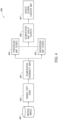
Figure 2 shows one implementation of how a trained DeformationNet may be used to perform image stabilization, according to one non-limiting illustrated implementation. -
Figure 3 shows one implementation of how a trained DeformationNet may be used to perform contour mask transferring, according to one non-limiting illustrated implementation. -
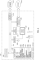
Figure 4 shows two implementations of how a contour mask to coregister via DeformationNet may be selected, according to one non-limiting illustrated implementation. -
Figure 5 shows an example of a slice where good segmentation probability maps and quality scores are derived and an example of a slice where bad segmentation probability maps and quality scores are derived, according to one non-limiting illustrated implementation. -
Figure 6 is an example computing environment for one or more implementations of the present disclosure. - The invention is defined in the appended independent claims. Embodiments of the invention are defined in the appended dependent claims.
- The implementation described herein is a novel framework for unsupervised coregistration using CNNs, which is referred to herein as DeformationNet. DeformationNet takes a fully unsupervised approach to image coregistration. Advantageously, DeformationNet also explicitly stabilizes images or transfers contour masks across images. For the architecture of DeformationNet, global alignment is learned via affine deformations in addition to the DDF, and an unsupervised loss function is maintained. The use of an unsupervised loss function obviates the need for explicit human-derived annotations on the data, which is advantageous since acquisition of those annotations is one of the major challenges for supervised and semi-supervised CNNs. DeformationNet is also unique in that, in at least some implementations, it applies an additional spatial transformation layer at the end of each transformation step, which provides the ability to "fine-tune" the previously predicted transformation so that the network might correct previous transformation errors.
- One implementation of the training phase of the DeformationNet system is shown in
Figure 1 . In at least some implementations, training of DeformationNet has two main processes: - 1. Training a Global Network to learn global image alignment via an affine matrix for warping an inputted target image onto an inputted source image coordinate system (102, 103, and 105); and
- 2. Training a Local Network to learn a DDF for warping localized features of an inputted target image onto an inputted source image (105 and 106).
- In at least some implementations, each pair of source and target images from a medical images database (101) represents two cardiac MR images from the same patient and possibly the same study. These cardiac MR series may include but are not limited to: Delayed Enhancement short axis (SAX) images, Perfusion SAX images, SSFP SAX images, T1/T2/T2* mapping SAX images, etc.
- An affine transformation matrix with N or more affine transformation parameters, where N is an integer greater than or equal to 0, is learned via a Global Network (104) wherein the input is a pair of images that includes a source image (103) and a target image (102). The learned affine transformation parameters are defined as those parameters which, when applied to the target image, align the target image with the source image. In at least some implementations, the target image is resized to match the size of the source image before the affine matrix is learned.
- In at least some implementations, the Global Network (104) is a regression network. A version of the Global Network (104) includes 32 initial convolutional filters. At least some implementations downsample using strides in the convolutional layers and there are 2 convolutional layers with kernel size 3, a batch normalization layer with a momentum rate, a dropout layer, and a ReLU nonlinearity layer before each downsampling operation. In at least some implementations, the last layer of the Global Network (104) is a dense layer mapping to the desired number of affine parameters.
- In at least some implementations, the affine parameter outputs of the Global Network (104) are used as input to another affine spatial transformation layer that is bounded by different scaling factors for rotation, scaling, and zooming. The scaling factors control the amount of affine deformations that can be made to the target image. In at least some implementations, the affine spatial transformation matrix output by the affine spatial transformation layer includes a regularization operation that is implemented in the form of a bending energy loss function. A gradient energy loss function for regularization of the affine spatial transformation matrix may also be used, for example. This regularization further prevents the learned affine spatial transformation matrix from generating unrealistically large transformations.
- In at least some implementations, a DDF is learned via a Local Network (106) wherein the input is a pair that includes a source image (102) and a target image (103). In some implementations, the target image (102) has first been warped onto the source image coordinates via an affine transformation matrix learned in the global network(104), providing a warped target image (105) to be input into the Local Network (106).
- In at least some implementations, the Local Network (106) is a neural network architecture that includes a downsampling path and then an upsampling path. A version of such Local Network includes 32 initial convolutional filters and skip connections between the corresponding downsampling and upsampling layers. At least some implementations downsample using strides in the convolutional layers and there are 2 convolutional layers with kernel size 3, a batch normalization layer with a momentum rate, a dropout layer, and a ReLU nonlinearity layer before each downsampling or upsampling operation. This upsampling allows the DDF to be the same size as the inputted source and target images provided that padding was used.
- In at least some implementations, the learned DDF output of the Local Network (106) goes through a freeform similarity spatial transformation layer. As an example, this freeform similarity spatial transformation layer can include affine transformations or dense freeform deformation field warpings5, or both. If affine transformations are used, they may be scaled to control the amount of deformations that can be made to the target images. In at least some implementations, the DDF also includes a regularization operation that is implemented in the form of a bending energy loss functions. A gradient energy loss function may also be used to regularize the DDF. This regularization prevents the learned DDF from generating deformations that are unrealistically large.
- In at least some implementations, the CNN models may be updated via backpropagation with an adam optimizer and a mutual information loss function between the source image and the target image that has been warped by the DDF (i.e., warped target image 105). Adam optimizer adjusts its learning rate through training using both the first and second moments of the backpropagated gradients. Other non-limiting examples of optimizers that may be used include stochastic gradient descent, minibatch gradient descent, adagrad, and root mean squared propagation. Other non-limiting examples of loss functions may include root mean squared error, L2 loss, L2 loss with center weighting, and cross correlation loss7 between the source image and the DDF that has been applied to the target image. These loss functions only depend on the raw input data and what the DeformationNet learns from that raw data. Advantageously, the absence of any dependence on explicit hand-annotations allows for this system to be fully unsupervised.
- Weights of the trained Global Network (104) and Local Network (106) can be stored in storage devices including hard disks and solid state drives to be used later for image stabilization or segmentation mask transferring.
-
Figure 2 illustrates an implementation of performing inference on a trained DeformationNet for image stabilization. In this implementation, the input to DeformationNet includes a source image (202), and a target image (203) to be stabilized by warping the target image onto the source image. These image pairings may be selected from a database of medical images (201). Using the trained DeformationNet (204), discussed above, a DDF (205) with respect to the source image (202) is inferred. This DDF (205) is applied to the target image (203), creating a warped target image (206) that is stabilized with respect to the source image (202). The newly stabilized target image (206) may be displayed to the user via a display (207) and stored in a warped images database (209) including hard disks and solid state drives. - Image pairings that may be used for image stabilization inference include but are not limited to: images from the same slice of a cardiac MR image volume but captured at different time points; images from the same time point of a cardiac MR image volume but different slices; images from any image of the same MR image volume; images from distinct MR image volumes; images from other medical imaging that involve a time series such as breast, liver, or prostate DCE-MRI (dynamic contrast enhancement MRI); or images from fluoroscopy imaging.
-
Figure 3 illustrates one implementation of performing inference with a trained DeformationNet for transferring segmentation masks from one image to another. In at least some of the implementations, the input to DeformationNet is a pair of 2D cardiac SAX MR images (source image 302 and target image 303) from a database of medical images (301), where one of the images has a corresponding segmentation mask (304) of ventricular contours, for instance, to include the left ventricular endocardium (LV endo), left ventricular epicardium (LV epi), and/or right ventricular endocardium (RV endo), for example. In at least some of the implementations, the segmentation mask (304) may correspond to the target image (303). Using the trained DeformationNet (305), a DDF (306) with respect to the source image is inferred. This DDF (306) is applied to the segmentation mask (304) corresponding to the target image (303) creating a warped segmentation mask (307) that has been warped onto the source image. The newly warped segmentation mask (307) can be displayed to the user via a display (308) and stored in a warped segmentation masks database (310) including but not limited to hard disks and solid state drives. - Implementations of attaining the segmentations masks (304) shown in
Figure 3 include, but are not limited to: having a user manually create the segmentation mask; and using a heuristic involving a previously trained CNN model to automatically create the segmentation mask. -
Figure 4 illustrates one implementation of using a heuristic and previously trained CNN to select a segmentation mask to transfer to other images. In this implementation, a group of 2D cardiac SAX MR images (401) is chosen for which segmentations are needed. Those images (401) are used as input to a previously trained CNN (402), as discussed above. In at least some implementations, the CNN (402) was previously trained to segment masks for the LV epi, LV endo, and RV endo in 2D SSFP MRs images. In those implementations, the output of the CNN (402) is a segmentation probability map (403) on a per-pixel basis for each 2D image. - The CNN (402) may not be able to accurately predict segmentations for every image, so it may be important to choose images with good quality segmentation masks as the target image for (303) (
Figure 3 ). The segmentation probability maps (403) that are outputted from the previously trained CNN (402) are used to compute foreground map scores (404) and background map scores (405) for the given image. The map scores (404) and (405) are computed per pixel. The foreground mask scores (404) represent the probability that an image pixel belongs to one of the ventricular masks, and the background mask scores (405) represent the probability that the image pixel does not belong to one of the ventricular masks. The foreground map score (404) is calculated by taking the average of all probability map values above 0.5. The background map score (405) is calculated by taking the distance from 1 of all the probability map values below 0.5. A mask quality score (406) for that given slice prediction is then calculated by multiplying the background mask score (405) with the foreground mask score (404). - The general actions of the above described possible heuristic implementation are explained in the following example pseudocode:
- 1. for image in set of 2D images:
- a. probability_map = Previously_Trained_CNN_Segmentor(image)
- b. foreground_map_values = values of probability_map > 0.5
- c. foreground_score = mean(foreground_map_values)
- d. background_map_values = 1 - (values of probability_map <= 0.5)
- e. background_score = mean(background_mapvalues)
- f. quallity_score = foreground_score * background_score
- 2. select images with best quality
- In at least some implementations, the image with the segmentation probability mask corresponding to the highest quality score across the group of 2D images will be treated as the single target image (407) and some or all of the other images will be treated as source images to which the target image's segmentation mask (304) will be warped.
-
Figure 5 shows an example of how the heuristic described above may work in practice. Images (502) and (508) are examples of 2D SAX MR images that are to be fed into the CNN (402) (Figure 4 ). Images (504) and (510) are the probability map outputs of the CNN (402) for the LV epi of the images (502) and (508), respectively, represented as contour maps. The image (504) represents a good probability map. It has a clear boundary of high probability (represented by the black line of 0.8) around the LV epi and the probability drops quickly outside of the LV epi area. The image (510) represents a bad probability map. The contours around the LV epi are overall fairly low, there is only high probability at the very center of the LV epi. Additionally, there is a change in probability far outside of the LV epi area. Foreground and background maps for the images (504) and (510) are represented as contours in images (506) and (512), respectively. The black contours represent the foreground map values as calculated by act 1.b in the pseudocode above and the white contours represent the background map values as calculated by act 1.d in the pseudocode. Image (506) has high probability for the foreground map and background map, which would give it a high quality score. Image (510) has high probability for the background map but low for the foreground map, which would give it a low quality score and it would likely not be used as the segmentation mask to transfer across images. -
Figure 6 shows a processor-baseddevice 604 suitable for implementing the various functionality described herein. Although not required, some portion of the implementations will be described in the general context of processor-executable instructions or logic, such as program application modules, objects, or macros being executed by one or more processors. Those skilled in the relevant art will appreciate that the described implementations, as well as other implementations, can be practiced with various processor-based system configurations, including handheld devices, such as smartphones and tablet computers, wearable devices, multiprocessor systems, microprocessor-based or programmable consumer electronics, personal computers ("PCs"), network PCs, minicomputers, mainframe computers, and the like. - The processor-based
device 604 may include one ormore processors 606, asystem memory 608 and asystem bus 610 that couples various system components including thesystem memory 608 to the processor(s) 606. The processor-baseddevice 604 will at times be referred to in the singular herein, but this is not intended to limit the implementations to a single system, since in certain implementations, there will be more than one system or other networked computing device involved. Non-limiting examples of commercially available systems include, but are not limited to, ARM processors from a variety of manufactures, Core microprocessors from Intel Corporation, U.S.A., PowerPC microprocessor from IBM, Sparc microprocessors from Sun Microsystems, Inc., PA-RISC series microprocessors from Hewlett-Packard Company, 68xxx series microprocessors from Motorola Corporation. - The processor(s) 606 may be any logic processing unit, such as one or more central processing units (CPUs), microprocessors, digital signal processors (DSPs), application-specific integrated circuits (ASICs), field programmable gate arrays (FPGAs), etc. Unless described otherwise, the construction and operation of the various blocks shown in
Figure 6 are of conventional design. As a result, such blocks need not be described in further detail herein, as they will be understood by those skilled in the relevant art. - The
system bus 610 can employ any known bus structures or architectures, including a memory bus with memory controller, a peripheral bus, and a local bus. Thesystem memory 608 includes read-only memory ("ROM") 1012 and random access memory ("RAM") 614. A basic input/output system ("BIOS") 616, which can form part of theROM 612, contains basic routines that help transfer information between elements within processor-baseddevice 604, such as during start-up. Some implementations may employ separate buses for data, instructions and power. - The processor-based
device 604 may also include one or more solid state memories, for instance Flash memory or solid state drive (SSD) 618, which provides nonvolatile storage of computer-readable instructions, data structures, program modules and other data for the processor-baseddevice 604. Although not depicted, the processor-baseddevice 604 can employ other nontransitory computer- or processor-readable media, for example a hard disk drive, an optical disk drive, or memory card media drive. - Program modules can be stored in the
system memory 608, such as anoperating system 630, one ormore application programs 632, other programs ormodules 634,drivers 636 andprogram data 638. - The
application programs 632 may, for example, include panning / scrolling 632a. Such panning / scrolling logic may include, but is not limited to logic that determines when and/or where a pointer (e.g., finger, stylus, cursor) enters a user interface element that includes a region having a central portion and at least one margin. Such panning / scrolling logic may include, but is not limited to logic that determines a direction and a rate at which at least one element of the user interface element should appear to move, and causes updating of a display to cause the at least one element to appear to move in the determined direction at the determined rate. The panning /scrolling logic 632a may, for example, be stored as one or more executable instructions. The panning /scrolling logic 632a may include processor and/or machine executable logic or instructions to generate user interface objects using data that characterizes movement of a pointer, for example data from a touch-sensitive display or from a computer mouse or trackball, or other user interface device. - The
system memory 608 may also includecommunications programs 640, for example a server and/or a Web client or browser for permitting the processor-baseddevice 604 to access and exchange data with other systems such as user computing systems, Web sites on the Internet, corporate intranets, or other networks as described below. Thecommunications programs 640 in the depicted implementation is markup language based, such as Hypertext Markup Language (HTML), Extensible Markup Language (XML) or Wireless Markup Language (WML), and operates with markup languages that use syntactically delimited characters added to the data of a document to represent the structure of the document. A number of servers and/or Web clients or browsers are commercially available such as those from Mozilla Corporation of California and Microsoft of Washington. - While shown in
Figure 6 as being stored in thesystem memory 608, theoperating system 630,application programs 632, other programs/modules 634,drivers 636,program data 638 and server and/orbrowser 640 can be stored on any other of a large variety of nontransitory processor-readable media (e.g., hard disk drive, optical disk drive, SSD and/or flash memory). - A user can enter commands and information via a pointer, for example through input devices such as a
touch screen 648 via afinger 644a, stylus 644b, or via a computer mouse ortrackball 644c which controls a cursor. Other input devices can include a microphone, joystick, game pad, tablet, scanner, biometric scanning device, etc. These and other input devices (i.e., "I/O devices") are connected to the processor(s) 606 through an interface 646 such as touch-screen controller and/or a universal serial bus ("USB") interface that couples user input to thesystem bus 610, although other interfaces such as a parallel port, a game port or a wireless interface or a serial port may be used. Thetouch screen 648 can be coupled to thesystem bus 610 via avideo interface 650, such as a video adapter to receive image data or image information for display via thetouch screen 648. Although not shown, the processor-baseddevice 604 can include other output devices, such as speakers, vibrator, haptic actuator, etc. - The processor-based
device 604 may operate in a networked environment using one or more of the logical connections to communicate with one or more remote computers, servers and/or devices via one or more communications channels, for example, one ormore networks - When used in a networking environment, the processor-based
device 604 may include one or more wired orwireless communications interfaces Internet 614a or cellular network. - In a networked environment, program modules, application programs, or data, or portions thereof, can be stored in a server computing system (not shown). Those skilled in the relevant art will recognize that the network connections shown in
Figure 6 are only some examples of ways of establishing communications between computers, and other connections may be used, including wirelessly. - For convenience, the processor(s) 606,
system memory 608, network andcommunications interfaces system bus 610, thereby providing connectivity between the above-described components. In alternative implementations of the processor-baseddevice 604, the above-described components may be communicably coupled in a different manner than illustrated inFigure 6 . For example, one or more of the above-described components may be directly coupled to other components, or may be coupled to each other, via intermediary components (not shown). In some implementations,system bus 610 is omitted and the components are coupled directly to each other using suitable connections. -
- 1. Norman, B., Pedoia, V. & Majumdar, S. Use of 2D U-Net Convolutional Neural Networks for Automated Cartilage and Meniscus Segmentation of Knee MR Imaging Data to Determine Relaxometry and Morphometry. Radiology 288, 177-185 (2018).
- 2. Lieman-Sifry, J., Le, M., Lau, F., Sall, S. & Golden, D. FastVentricle: Cardiac Segmentation with ENet. in Functional Imaging and Modelling of the Heart 127-138 (Springer International Publishing, 2017).
- 3. Shen, D. & Davatzikos, C. HAMMER: hierarchical attribute matching mechanism for elastic registration. IEEE Trans. Med Imaging 21, 1421-1439 (2002).
- 4. Ashbumer, J. & Friston, K. J. Voxel-Based Morphometry-The Methods. Neuroimage 11, 805-821 (2000).
- 5. Rueckert, D. et al. Nonrigid registration using free-form deformations: application to breast MR images. IEEE Trans. Med Imaging 18, 712-721 (1999).
- 6. Hu, Y. et al. Label-driven weakly-supervised learning for multimodal deformarle image registration. in 2018 IEEE 15th International Symposium on Biomedical Imaging (ISBI 2018) 1070-1074 (2018).
- 7. Balakrishnan, G., Zhao, A, Sabuncu, M. R., Guttag, J. & Dalca, A V. An Unsupervised Leaming Model for Deformable Medical Image Registration. in Proceedings of the IEEE Conference on Computer Vision and Pattern Recognition 9252-9260 (2018).
- 8. Lin, C.-H. & Lucey, S. Inverse Compositional Spatial Transformer Networks. arXiv [cs. CV] (2016).
Claims (13)
- A machine learning system, comprising:at least one nontransitory processor-readable storage medium that stores at least one of processor-executable instructions or data; andat least one processor communicably coupled to the at least one nontransitory processor-readable storage medium, in operation the at least one processor:receives learning data comprising a plurality of batches of unlabelled image sets, wherein each image set comprises a source image and target image that each represents a medical image scan of at least one patient;trains one or more convolutional neural networks (CNNs) models, based on the learning data, to learn one or more transformation functions for coregistration of a target image onto a source image,wherein the one or more CNNs models include a global network component that learns an affine transformation matrix and a local network component that learns a dense deformation field, andwherein the global network component precedes the local network component in the one or more CNNs models; andstores the one or more trained CNN models in the at least one nontransitory processor-readable storage medium of the machine learning system.
- The machine learning system of claim 1 wherein the at least one processor trains the one or more CNN models using an unsupervised training algorithm, and wherein
the unsupervised training algorithm comprises a loss function that is calculated from a pair of source and target images and is not computed from any explicit human-created annotations on the images. - The machine learning system of claim 2 wherein the loss function includes a per-pixel root mean squared error between the source and target images.
- The machine learning system of claim 2 wherein a differentiable objective function includes mutual information loss between the source and target images, an L2 loss between the source and target images, a center-weighted L2 loss function between the source and target images, or a normalized cross correlation loss function between the source and target images.
- The machine learning system of claim 1 wherein the transformation functions include at least one of (a) affine transformations or (b) dense, nonlinear correspondence maps.
- The machine learning system of claim 1 wherein the affine transformation matrix is calculated on the target image with respect to the source image.
- The machine learning system of claim 1 wherein the global network model comprises a contracting path that includes at least one group of layers that comprises at least one of each of the following: convolution layer, max pooling layer, batch normalization layer, and dropout layer.
- The machine learning system of claim 1 wherein the affine transformation matrix output by the global network model is inputted to an affine spatial transformation layer.
- The machine learning system of claim 1 wherein the affine transformation matrix includes a regularization operation.
- The machine learning system of claim 1 wherein the local network model comprises a contracting path and an expanding path,the contracting path includes one or more convolutional layers and one or more pooling layers, each pooling layer preceded by at least one convolutional layer, andthe expanding path includes a number of convolutional layers and a number of upsampling layers, each upsampling layer preceded by at least one convolutional layer, and each upsampling layer comprises a transpose convolution operation which performs at least one of an upsampling operation and an interpolation operation with a learned kernel, or an upsampling operation followed by an interpolation operation.
- The machine learning system of claim 1 wherein the local network dense deformation field output is inputted to a freeform similarity spatial transformer.
- The machine learning system of claim 11 wherein the freeform similarity spatial transformer includes at least one of an affine transformation or a dense freeform deformation field warping.
- The machine learning system of claim 1 wherein the local network dense deformation field output is regularized by a regularization operation.
Applications Claiming Priority (2)
| Application Number | Priority Date | Filing Date | Title |
|---|---|---|---|
| US201862722663P | 2018-08-24 | 2018-08-24 | |
| PCT/US2019/047552 WO2020041503A1 (en) | 2018-08-24 | 2019-08-21 | Deep learning-based coregistration |
Publications (3)
| Publication Number | Publication Date |
|---|---|
| EP3821377A1 EP3821377A1 (en) | 2021-05-19 |
| EP3821377A4 EP3821377A4 (en) | 2022-04-20 |
| EP3821377B1 true EP3821377B1 (en) | 2025-03-26 |
Family
ID=69591123
Family Applications (1)
| Application Number | Title | Priority Date | Filing Date |
|---|---|---|---|
| EP19852781.4A Active EP3821377B1 (en) | 2018-08-24 | 2019-08-21 | Deep learning-based coregistration |
Country Status (6)
| Country | Link |
|---|---|
| US (2) | US20210216878A1 (en) |
| EP (1) | EP3821377B1 (en) |
| JP (1) | JP7433297B2 (en) |
| CN (1) | CN112602099A (en) |
| ES (1) | ES3032182T3 (en) |
| WO (1) | WO2020041503A1 (en) |
Families Citing this family (23)
| Publication number | Priority date | Publication date | Assignee | Title |
|---|---|---|---|---|
| DE102019123455A1 (en) | 2018-09-04 | 2020-03-05 | Nvidia Corporation | COMMON SYNTHESIS AND PLACEMENT OF OBJECTS IN SCENES |
| US12573028B2 (en) * | 2019-08-14 | 2026-03-10 | Nvidia Corporation | Neural network for image registration and image segmentation trained using a registration simulator |
| US11693919B2 (en) * | 2020-06-22 | 2023-07-04 | Shanghai United Imaging Intelligence Co., Ltd. | Anatomy-aware motion estimation |
| US11521323B2 (en) * | 2020-10-21 | 2022-12-06 | Shanghai United Imaging Intelligence Co., Ltd. | Systems and methods for generating bullseye plots |
| US12518472B2 (en) * | 2020-11-16 | 2026-01-06 | Google Llc | Deformable neural radiance fields |
| US11822620B2 (en) * | 2021-02-18 | 2023-11-21 | Microsoft Technology Licensing, Llc | Personalized local image features using bilevel optimization |
| US12602754B2 (en) | 2021-03-04 | 2026-04-14 | Rensselaer Polytechnic Institute | Dynamic imaging and motion artifact reduction through deep learning |
| CN113112534B (en) * | 2021-04-20 | 2022-10-18 | 安徽大学 | Three-dimensional biomedical image registration method based on iterative self-supervision |
| CN113240699B (en) * | 2021-05-20 | 2022-02-08 | 推想医疗科技股份有限公司 | Image processing method and device, model training method and device, and electronic equipment |
| CN113822792B (en) * | 2021-06-15 | 2025-06-10 | 腾讯科技(深圳)有限公司 | Image registration method, device, equipment and storage medium |
| CN113723456B (en) * | 2021-07-28 | 2023-10-17 | 南京邮电大学 | Automatic astronomical image classification method and system based on unsupervised machine learning |
| CN113763441B (en) * | 2021-08-25 | 2024-01-26 | 中国科学院苏州生物医学工程技术研究所 | Unsupervised learning medical image registration method and system |
| CN114035656B (en) * | 2021-11-09 | 2023-11-14 | 吕梁学院 | Medical image processing device and method based on deep learning |
| CN115482150A (en) * | 2021-12-01 | 2022-12-16 | 万达信息股份有限公司 | A method for brain MRI image registration based on self-supervised learning |
| US20230274386A1 (en) * | 2022-02-28 | 2023-08-31 | Ford Global Technologies, Llc | Systems and methods for digital display stabilization |
| CN114693755B (en) * | 2022-05-31 | 2022-08-30 | 湖南大学 | Non-rigid registration method and system for maximum moment and spatial consistency of multimodal images |
| KR102603177B1 (en) * | 2022-06-03 | 2023-11-17 | 주식회사 브라이토닉스이미징 | System for spatial normalization of image, quantification using spatial normalization and method thereof |
| JP7741454B2 (en) * | 2022-07-26 | 2025-09-18 | Ntt株式会社 | Learning device, learning method and program |
| CN115291730B (en) * | 2022-08-11 | 2023-08-15 | 北京理工大学 | A wearable bioelectric device and bioelectric action recognition and self-calibration method |
| CN117173401B (en) * | 2022-12-06 | 2024-05-03 | 南华大学 | Semi-supervised medical image segmentation method and system based on cross guidance and feature level consistency dual regularization |
| US12586218B2 (en) * | 2023-03-09 | 2026-03-24 | Shanghai United Imaging Intelligence Co., Ltd. | Motion estimation with anatomical integrity |
| CN118470253B (en) * | 2024-07-15 | 2024-09-13 | 湖南大学 | A surface mesh reconstruction method for medical images |
| CN119850692B (en) * | 2024-12-25 | 2025-10-28 | 上海交通大学 | Anatomical consistency self-supervised learning method and system for synthesizable and decomposable medical images |
Family Cites Families (8)
| Publication number | Priority date | Publication date | Assignee | Title |
|---|---|---|---|---|
| GB0917154D0 (en) * | 2009-09-30 | 2009-11-11 | Imp Innovations Ltd | Method and apparatus for processing medical images |
| US9552526B2 (en) * | 2013-12-19 | 2017-01-24 | University Of Memphis Research Foundation | Image processing using cellular simultaneous recurrent network |
| WO2015128775A1 (en) * | 2014-02-27 | 2015-09-03 | Koninklijke Philips N.V. | Unsupervised training for an atlas-based registration |
| CN108603922A (en) * | 2015-11-29 | 2018-09-28 | 阿特瑞斯公司 | Automatic cardiac volume is divided |
| US20170337682A1 (en) * | 2016-05-18 | 2017-11-23 | Siemens Healthcare Gmbh | Method and System for Image Registration Using an Intelligent Artificial Agent |
| WO2017223560A1 (en) | 2016-06-24 | 2017-12-28 | Rensselaer Polytechnic Institute | Tomographic image reconstruction via machine learning |
| CN107545584B (en) * | 2017-04-28 | 2021-05-18 | 上海联影医疗科技股份有限公司 | Method, device and system for positioning region of interest in medical image |
| US20190286990A1 (en) * | 2018-03-19 | 2019-09-19 | AI Certain, Inc. | Deep Learning Apparatus and Method for Predictive Analysis, Classification, and Feature Detection |
-
2019
- 2019-08-21 US US17/270,810 patent/US20210216878A1/en active Pending
- 2019-08-21 EP EP19852781.4A patent/EP3821377B1/en active Active
- 2019-08-21 ES ES19852781T patent/ES3032182T3/en active Active
- 2019-08-21 CN CN201980055199.9A patent/CN112602099A/en active Pending
- 2019-08-21 WO PCT/US2019/047552 patent/WO2020041503A1/en not_active Ceased
- 2019-08-21 JP JP2021510116A patent/JP7433297B2/en active Active
-
2025
- 2025-01-17 US US19/030,182 patent/US20250165791A1/en active Pending
Also Published As
| Publication number | Publication date |
|---|---|
| EP3821377A4 (en) | 2022-04-20 |
| JP2021535482A (en) | 2021-12-16 |
| US20210216878A1 (en) | 2021-07-15 |
| CN112602099A (en) | 2021-04-02 |
| WO2020041503A1 (en) | 2020-02-27 |
| EP3821377A1 (en) | 2021-05-19 |
| JP7433297B2 (en) | 2024-02-19 |
| ES3032182T3 (en) | 2025-07-16 |
| US20250165791A1 (en) | 2025-05-22 |
Similar Documents
| Publication | Publication Date | Title |
|---|---|---|
| US20250165791A1 (en) | Deep learning-based coregistration | |
| Shen et al. | Networks for joint affine and non-parametric image registration | |
| US10600184B2 (en) | Automated segmentation utilizing fully convolutional networks | |
| Yu et al. | Hallucinating very low-resolution unaligned and noisy face images by transformative discriminative autoencoders | |
| US11348227B2 (en) | Image registration using a fully convolutional network | |
| Xu et al. | BMAnet: Boundary mining with adversarial learning for semi-supervised 2D myocardial infarction segmentation | |
| WO2019241155A1 (en) | Simulating abnormalities in medical images with generative adversarial networks | |
| JP2019504659A (en) | Automated cardiac volume segmentation | |
| JP2021511579A (en) | Image processing system and image processing method | |
| WO2021017168A1 (en) | Image segmentation method, apparatus, device, and storage medium | |
| CN113298742A (en) | Multi-modal retinal image fusion method and system based on image registration | |
| US10297035B2 (en) | Image processing apparatus, image processing method, and program | |
| Chen et al. | A multi-scale large kernel attention with U-Net for medical image registration: Y. Chen et al. | |
| Hu et al. | Towards effective learning for face super-resolution with shape and pose perturbations | |
| EP4073755B1 (en) | Compensation of organ deformation for medical image registration | |
| Jiang et al. | Deformable medical image registration based on multi-level transformation progressive and image enhancement | |
| Bai et al. | NODER: Image sequence regression based on neural ordinary differential equations | |
| CN114708471A (en) | Cross-modal image generation method, device, electronic device and storage medium | |
| Ranem et al. | Nca-morph: Medical image registration with neural cellular automata | |
| CN115393374B (en) | Semantic segmentation method and system for lumbar MRI images based on divergence loss | |
| Zhang et al. | Deformable image registration with strategic integration pyramid framework for brain MRI | |
| CN115511908A (en) | Medical image segmentation method, device, computer equipment and storage medium | |
| US20240346671A1 (en) | Deformable image registration | |
| US20250285266A1 (en) | Flexible transformer for multiple heterogeneous image input for medical imaging analysis | |
| Yin et al. | HMA-Net: A Hybrid Manhattan Attention Network for unsupervised affine medical image registration |
Legal Events
| Date | Code | Title | Description |
|---|---|---|---|
| STAA | Information on the status of an ep patent application or granted ep patent |
Free format text: STATUS: THE INTERNATIONAL PUBLICATION HAS BEEN MADE |
|
| PUAI | Public reference made under article 153(3) epc to a published international application that has entered the european phase |
Free format text: ORIGINAL CODE: 0009012 |
|
| STAA | Information on the status of an ep patent application or granted ep patent |
Free format text: STATUS: REQUEST FOR EXAMINATION WAS MADE |
|
| 17P | Request for examination filed |
Effective date: 20210212 |
|
| AK | Designated contracting states |
Kind code of ref document: A1 Designated state(s): AL AT BE BG CH CY CZ DE DK EE ES FI FR GB GR HR HU IE IS IT LI LT LU LV MC MK MT NL NO PL PT RO RS SE SI SK SM TR |
|
| DAV | Request for validation of the european patent (deleted) | ||
| DAX | Request for extension of the european patent (deleted) | ||
| A4 | Supplementary search report drawn up and despatched |
Effective date: 20220318 |
|
| RIC1 | Information provided on ipc code assigned before grant |
Ipc: G06T 7/33 20170101ALN20220314BHEP Ipc: G06T 7/00 20170101ALI20220314BHEP Ipc: G06N 3/04 20060101ALI20220314BHEP Ipc: G06N 3/08 20060101AFI20220314BHEP |
|
| REG | Reference to a national code |
Ref country code: DE Ref legal event code: R079 Free format text: PREVIOUS MAIN CLASS: G06N0003080000 Ipc: G06N0003088000 Ref country code: DE Ref legal event code: R079 Ref document number: 602019067892 Country of ref document: DE Free format text: PREVIOUS MAIN CLASS: G06N0003080000 Ipc: G06N0003088000 |
|
| RIC1 | Information provided on ipc code assigned before grant |
Ipc: G06N 3/048 20230101ALN20240916BHEP Ipc: G06T 7/33 20170101ALN20240916BHEP Ipc: G06N 3/045 20230101ALI20240916BHEP Ipc: G06N 3/088 20230101AFI20240916BHEP |
|
| GRAP | Despatch of communication of intention to grant a patent |
Free format text: ORIGINAL CODE: EPIDOSNIGR1 |
|
| STAA | Information on the status of an ep patent application or granted ep patent |
Free format text: STATUS: GRANT OF PATENT IS INTENDED |
|
| INTG | Intention to grant announced |
Effective date: 20241025 |
|
| GRAS | Grant fee paid |
Free format text: ORIGINAL CODE: EPIDOSNIGR3 |
|
| GRAA | (expected) grant |
Free format text: ORIGINAL CODE: 0009210 |
|
| STAA | Information on the status of an ep patent application or granted ep patent |
Free format text: STATUS: THE PATENT HAS BEEN GRANTED |
|
| AK | Designated contracting states |
Kind code of ref document: B1 Designated state(s): AL AT BE BG CH CY CZ DE DK EE ES FI FR GB GR HR HU IE IS IT LI LT LU LV MC MK MT NL NO PL PT RO RS SE SI SK SM TR |
|
| REG | Reference to a national code |
Ref country code: GB Ref legal event code: FG4D |
|
| REG | Reference to a national code |
Ref country code: CH Ref legal event code: EP |
|
| REG | Reference to a national code |
Ref country code: DE Ref legal event code: R096 Ref document number: 602019067892 Country of ref document: DE |
|
| REG | Reference to a national code |
Ref country code: IE Ref legal event code: FG4D |
|
| PG25 | Lapsed in a contracting state [announced via postgrant information from national office to epo] |
Ref country code: RS Free format text: LAPSE BECAUSE OF FAILURE TO SUBMIT A TRANSLATION OF THE DESCRIPTION OR TO PAY THE FEE WITHIN THE PRESCRIBED TIME-LIMIT Effective date: 20250626 |
|
| PG25 | Lapsed in a contracting state [announced via postgrant information from national office to epo] |
Ref country code: FI Free format text: LAPSE BECAUSE OF FAILURE TO SUBMIT A TRANSLATION OF THE DESCRIPTION OR TO PAY THE FEE WITHIN THE PRESCRIBED TIME-LIMIT Effective date: 20250326 |
|
| REG | Reference to a national code |
Ref country code: LT Ref legal event code: MG9D |
|
| PG25 | Lapsed in a contracting state [announced via postgrant information from national office to epo] |
Ref country code: NO Free format text: LAPSE BECAUSE OF FAILURE TO SUBMIT A TRANSLATION OF THE DESCRIPTION OR TO PAY THE FEE WITHIN THE PRESCRIBED TIME-LIMIT Effective date: 20250626 |
|
| PG25 | Lapsed in a contracting state [announced via postgrant information from national office to epo] |
Ref country code: HR Free format text: LAPSE BECAUSE OF FAILURE TO SUBMIT A TRANSLATION OF THE DESCRIPTION OR TO PAY THE FEE WITHIN THE PRESCRIBED TIME-LIMIT Effective date: 20250326 |
|
| REG | Reference to a national code |
Ref country code: ES Ref legal event code: FG2A Ref document number: 3032182 Country of ref document: ES Kind code of ref document: T3 Effective date: 20250716 |
|
| PG25 | Lapsed in a contracting state [announced via postgrant information from national office to epo] |
Ref country code: LV Free format text: LAPSE BECAUSE OF FAILURE TO SUBMIT A TRANSLATION OF THE DESCRIPTION OR TO PAY THE FEE WITHIN THE PRESCRIBED TIME-LIMIT Effective date: 20250326 |
|
| PG25 | Lapsed in a contracting state [announced via postgrant information from national office to epo] |
Ref country code: BG Free format text: LAPSE BECAUSE OF FAILURE TO SUBMIT A TRANSLATION OF THE DESCRIPTION OR TO PAY THE FEE WITHIN THE PRESCRIBED TIME-LIMIT Effective date: 20250326 Ref country code: GR Free format text: LAPSE BECAUSE OF FAILURE TO SUBMIT A TRANSLATION OF THE DESCRIPTION OR TO PAY THE FEE WITHIN THE PRESCRIBED TIME-LIMIT Effective date: 20250627 |
|
| REG | Reference to a national code |
Ref country code: NL Ref legal event code: MP Effective date: 20250326 |
|
| PG25 | Lapsed in a contracting state [announced via postgrant information from national office to epo] |
Ref country code: NL Free format text: LAPSE BECAUSE OF FAILURE TO SUBMIT A TRANSLATION OF THE DESCRIPTION OR TO PAY THE FEE WITHIN THE PRESCRIBED TIME-LIMIT Effective date: 20250326 |
|
| PG25 | Lapsed in a contracting state [announced via postgrant information from national office to epo] |
Ref country code: SE Free format text: LAPSE BECAUSE OF FAILURE TO SUBMIT A TRANSLATION OF THE DESCRIPTION OR TO PAY THE FEE WITHIN THE PRESCRIBED TIME-LIMIT Effective date: 20250326 |
|
| REG | Reference to a national code |
Ref country code: AT Ref legal event code: MK05 Ref document number: 1779679 Country of ref document: AT Kind code of ref document: T Effective date: 20250326 |
|
| PG25 | Lapsed in a contracting state [announced via postgrant information from national office to epo] |
Ref country code: SM Free format text: LAPSE BECAUSE OF FAILURE TO SUBMIT A TRANSLATION OF THE DESCRIPTION OR TO PAY THE FEE WITHIN THE PRESCRIBED TIME-LIMIT Effective date: 20250326 |
|
| PG25 | Lapsed in a contracting state [announced via postgrant information from national office to epo] |
Ref country code: PT Free format text: LAPSE BECAUSE OF FAILURE TO SUBMIT A TRANSLATION OF THE DESCRIPTION OR TO PAY THE FEE WITHIN THE PRESCRIBED TIME-LIMIT Effective date: 20250728 |
|
| PGFP | Annual fee paid to national office [announced via postgrant information from national office to epo] |
Ref country code: ES Payment date: 20250901 Year of fee payment: 7 |
|
| PGFP | Annual fee paid to national office [announced via postgrant information from national office to epo] |
Ref country code: DE Payment date: 20250827 Year of fee payment: 7 |
|
| PG25 | Lapsed in a contracting state [announced via postgrant information from national office to epo] |
Ref country code: PL Free format text: LAPSE BECAUSE OF FAILURE TO SUBMIT A TRANSLATION OF THE DESCRIPTION OR TO PAY THE FEE WITHIN THE PRESCRIBED TIME-LIMIT Effective date: 20250326 |
|
| PGFP | Annual fee paid to national office [announced via postgrant information from national office to epo] |
Ref country code: IT Payment date: 20250820 Year of fee payment: 7 |
|
| PGFP | Annual fee paid to national office [announced via postgrant information from national office to epo] |
Ref country code: GB Payment date: 20250827 Year of fee payment: 7 |
|
| PG25 | Lapsed in a contracting state [announced via postgrant information from national office to epo] |
Ref country code: AT Free format text: LAPSE BECAUSE OF FAILURE TO SUBMIT A TRANSLATION OF THE DESCRIPTION OR TO PAY THE FEE WITHIN THE PRESCRIBED TIME-LIMIT Effective date: 20250326 |
|
| PGFP | Annual fee paid to national office [announced via postgrant information from national office to epo] |
Ref country code: FR Payment date: 20250825 Year of fee payment: 7 |
|
| PG25 | Lapsed in a contracting state [announced via postgrant information from national office to epo] |
Ref country code: EE Free format text: LAPSE BECAUSE OF FAILURE TO SUBMIT A TRANSLATION OF THE DESCRIPTION OR TO PAY THE FEE WITHIN THE PRESCRIBED TIME-LIMIT Effective date: 20250326 |
|
| PG25 | Lapsed in a contracting state [announced via postgrant information from national office to epo] |
Ref country code: RO Free format text: LAPSE BECAUSE OF FAILURE TO SUBMIT A TRANSLATION OF THE DESCRIPTION OR TO PAY THE FEE WITHIN THE PRESCRIBED TIME-LIMIT Effective date: 20250326 |
|
| PG25 | Lapsed in a contracting state [announced via postgrant information from national office to epo] |
Ref country code: SK Free format text: LAPSE BECAUSE OF FAILURE TO SUBMIT A TRANSLATION OF THE DESCRIPTION OR TO PAY THE FEE WITHIN THE PRESCRIBED TIME-LIMIT Effective date: 20250326 |
|
| PG25 | Lapsed in a contracting state [announced via postgrant information from national office to epo] |
Ref country code: IS Free format text: LAPSE BECAUSE OF FAILURE TO SUBMIT A TRANSLATION OF THE DESCRIPTION OR TO PAY THE FEE WITHIN THE PRESCRIBED TIME-LIMIT Effective date: 20250726 |
|
| REG | Reference to a national code |
Ref country code: DE Ref legal event code: R097 Ref document number: 602019067892 Country of ref document: DE |
|
| PG25 | Lapsed in a contracting state [announced via postgrant information from national office to epo] |
Ref country code: DK Free format text: LAPSE BECAUSE OF FAILURE TO SUBMIT A TRANSLATION OF THE DESCRIPTION OR TO PAY THE FEE WITHIN THE PRESCRIBED TIME-LIMIT Effective date: 20250326 |
|
| PG25 | Lapsed in a contracting state [announced via postgrant information from national office to epo] |
Ref country code: CZ Free format text: LAPSE BECAUSE OF FAILURE TO SUBMIT A TRANSLATION OF THE DESCRIPTION OR TO PAY THE FEE WITHIN THE PRESCRIBED TIME-LIMIT Effective date: 20250326 |
|
| PLBE | No opposition filed within time limit |
Free format text: ORIGINAL CODE: 0009261 |
|
| STAA | Information on the status of an ep patent application or granted ep patent |
Free format text: STATUS: NO OPPOSITION FILED WITHIN TIME LIMIT |
|
| REG | Reference to a national code |
Ref country code: CH Ref legal event code: L10 Free format text: ST27 STATUS EVENT CODE: U-0-0-L10-L00 (AS PROVIDED BY THE NATIONAL OFFICE) Effective date: 20260211 |
|
| 26N | No opposition filed |
Effective date: 20260105 |
|
| REG | Reference to a national code |
Ref country code: CH Ref legal event code: H13 Free format text: ST27 STATUS EVENT CODE: U-0-0-H10-H13 (AS PROVIDED BY THE NATIONAL OFFICE) Effective date: 20260324 |
|
| PG25 | Lapsed in a contracting state [announced via postgrant information from national office to epo] |
Ref country code: MC Free format text: LAPSE BECAUSE OF FAILURE TO SUBMIT A TRANSLATION OF THE DESCRIPTION OR TO PAY THE FEE WITHIN THE PRESCRIBED TIME-LIMIT Effective date: 20250326 |
|
| PG25 | Lapsed in a contracting state [announced via postgrant information from national office to epo] |
Ref country code: LU Free format text: LAPSE BECAUSE OF NON-PAYMENT OF DUE FEES Effective date: 20250821 |
|
| PG25 | Lapsed in a contracting state [announced via postgrant information from national office to epo] |
Ref country code: CH Free format text: LAPSE BECAUSE OF NON-PAYMENT OF DUE FEES Effective date: 20250831 |