EP3821048B1 - Aluminium alloy fin stock material - Google Patents
Aluminium alloy fin stock material Download PDFInfo
- Publication number
- EP3821048B1 EP3821048B1 EP19762165.9A EP19762165A EP3821048B1 EP 3821048 B1 EP3821048 B1 EP 3821048B1 EP 19762165 A EP19762165 A EP 19762165A EP 3821048 B1 EP3821048 B1 EP 3821048B1
- Authority
- EP
- European Patent Office
- Prior art keywords
- stock material
- fin stock
- rolled
- material according
- content
- Prior art date
- Legal status (The legal status is an assumption and is not a legal conclusion. Google has not performed a legal analysis and makes no representation as to the accuracy of the status listed.)
- Active
Links
Images
Classifications
-
- C—CHEMISTRY; METALLURGY
- C22—METALLURGY; FERROUS OR NON-FERROUS ALLOYS; TREATMENT OF ALLOYS OR NON-FERROUS METALS
- C22C—ALLOYS
- C22C21/00—Alloys based on aluminium
-
- B—PERFORMING OPERATIONS; TRANSPORTING
- B23—MACHINE TOOLS; METAL-WORKING NOT OTHERWISE PROVIDED FOR
- B23K—SOLDERING OR UNSOLDERING; WELDING; CLADDING OR PLATING BY SOLDERING OR WELDING; CUTTING BY APPLYING HEAT LOCALLY, e.g. FLAME CUTTING; WORKING BY LASER BEAM
- B23K35/00—Rods, electrodes, materials, or media, for use in soldering, welding, or cutting
- B23K35/02—Rods, electrodes, materials, or media, for use in soldering, welding, or cutting characterised by mechanical features, e.g. shape
- B23K35/0222—Rods, electrodes, materials, or media, for use in soldering, welding, or cutting characterised by mechanical features, e.g. shape for use in soldering or brazing
- B23K35/0233—Sheets or foils
-
- B—PERFORMING OPERATIONS; TRANSPORTING
- B23—MACHINE TOOLS; METAL-WORKING NOT OTHERWISE PROVIDED FOR
- B23K—SOLDERING OR UNSOLDERING; WELDING; CLADDING OR PLATING BY SOLDERING OR WELDING; CUTTING BY APPLYING HEAT LOCALLY, e.g. FLAME CUTTING; WORKING BY LASER BEAM
- B23K35/00—Rods, electrodes, materials, or media, for use in soldering, welding, or cutting
- B23K35/02—Rods, electrodes, materials, or media, for use in soldering, welding, or cutting characterised by mechanical features, e.g. shape
- B23K35/0222—Rods, electrodes, materials, or media, for use in soldering, welding, or cutting characterised by mechanical features, e.g. shape for use in soldering or brazing
- B23K35/0233—Sheets or foils
- B23K35/0238—Sheets or foils layered
-
- B—PERFORMING OPERATIONS; TRANSPORTING
- B23—MACHINE TOOLS; METAL-WORKING NOT OTHERWISE PROVIDED FOR
- B23K—SOLDERING OR UNSOLDERING; WELDING; CLADDING OR PLATING BY SOLDERING OR WELDING; CUTTING BY APPLYING HEAT LOCALLY, e.g. FLAME CUTTING; WORKING BY LASER BEAM
- B23K35/00—Rods, electrodes, materials, or media, for use in soldering, welding, or cutting
- B23K35/22—Rods, electrodes, materials, or media, for use in soldering, welding, or cutting characterised by the composition or nature of the material
- B23K35/24—Selection of soldering or welding materials proper
- B23K35/28—Selection of soldering or welding materials proper with the principal constituent melting at less than 950°C
- B23K35/286—Al as the principal constituent
-
- B—PERFORMING OPERATIONS; TRANSPORTING
- B32—LAYERED PRODUCTS
- B32B—LAYERED PRODUCTS, i.e. PRODUCTS BUILT-UP OF STRATA OF FLAT OR NON-FLAT, e.g. CELLULAR OR HONEYCOMB, FORM
- B32B15/00—Layered products comprising a layer of metal
- B32B15/01—Layered products comprising a layer of metal all layers being exclusively metallic
- B32B15/016—Layered products comprising a layer of metal all layers being exclusively metallic all layers being formed of aluminium or aluminium alloys
-
- C—CHEMISTRY; METALLURGY
- C22—METALLURGY; FERROUS OR NON-FERROUS ALLOYS; TREATMENT OF ALLOYS OR NON-FERROUS METALS
- C22C—ALLOYS
- C22C21/00—Alloys based on aluminium
- C22C21/02—Alloys based on aluminium with silicon as the next major constituent
-
- C—CHEMISTRY; METALLURGY
- C22—METALLURGY; FERROUS OR NON-FERROUS ALLOYS; TREATMENT OF ALLOYS OR NON-FERROUS METALS
- C22C—ALLOYS
- C22C21/00—Alloys based on aluminium
- C22C21/10—Alloys based on aluminium with zinc as the next major constituent
-
- C—CHEMISTRY; METALLURGY
- C22—METALLURGY; FERROUS OR NON-FERROUS ALLOYS; TREATMENT OF ALLOYS OR NON-FERROUS METALS
- C22F—CHANGING THE PHYSICAL STRUCTURE OF NON-FERROUS METALS AND NON-FERROUS ALLOYS
- C22F1/00—Changing the physical structure of non-ferrous metals or alloys by heat treatment or by hot or cold working
- C22F1/04—Changing the physical structure of non-ferrous metals or alloys by heat treatment or by hot or cold working of aluminium or alloys based thereon
-
- C—CHEMISTRY; METALLURGY
- C22—METALLURGY; FERROUS OR NON-FERROUS ALLOYS; TREATMENT OF ALLOYS OR NON-FERROUS METALS
- C22F—CHANGING THE PHYSICAL STRUCTURE OF NON-FERROUS METALS AND NON-FERROUS ALLOYS
- C22F1/00—Changing the physical structure of non-ferrous metals or alloys by heat treatment or by hot or cold working
- C22F1/04—Changing the physical structure of non-ferrous metals or alloys by heat treatment or by hot or cold working of aluminium or alloys based thereon
- C22F1/053—Changing the physical structure of non-ferrous metals or alloys by heat treatment or by hot or cold working of aluminium or alloys based thereon of alloys with zinc as the next major constituent
-
- F—MECHANICAL ENGINEERING; LIGHTING; HEATING; WEAPONS; BLASTING
- F28—HEAT EXCHANGE IN GENERAL
- F28D—HEAT-EXCHANGE APPARATUS, NOT PROVIDED FOR IN ANOTHER SUBCLASS, IN WHICH THE HEAT-EXCHANGE MEDIA DO NOT COME INTO DIRECT CONTACT
- F28D1/00—Heat-exchange apparatus having stationary conduit assemblies for one heat-exchange medium only, the media being in contact with different sides of the conduit wall, in which the other heat-exchange medium is a large body of fluid, e.g. domestic or motor car radiators
- F28D1/02—Heat-exchange apparatus having stationary conduit assemblies for one heat-exchange medium only, the media being in contact with different sides of the conduit wall, in which the other heat-exchange medium is a large body of fluid, e.g. domestic or motor car radiators with heat-exchange conduits immersed in the body of fluid
- F28D1/04—Heat-exchange apparatus having stationary conduit assemblies for one heat-exchange medium only, the media being in contact with different sides of the conduit wall, in which the other heat-exchange medium is a large body of fluid, e.g. domestic or motor car radiators with heat-exchange conduits immersed in the body of fluid with tubular conduits
- F28D1/053—Heat-exchange apparatus having stationary conduit assemblies for one heat-exchange medium only, the media being in contact with different sides of the conduit wall, in which the other heat-exchange medium is a large body of fluid, e.g. domestic or motor car radiators with heat-exchange conduits immersed in the body of fluid with tubular conduits the conduits being straight
- F28D1/0535—Heat-exchange apparatus having stationary conduit assemblies for one heat-exchange medium only, the media being in contact with different sides of the conduit wall, in which the other heat-exchange medium is a large body of fluid, e.g. domestic or motor car radiators with heat-exchange conduits immersed in the body of fluid with tubular conduits the conduits being straight the conduits having a non-circular cross-section
- F28D1/05366—Assemblies of conduits connected to common headers, e.g. core type radiators
- F28D1/05391—Assemblies of conduits connected to common headers, e.g. core type radiators with multiple rows of conduits or with multi-channel conduits combined with a particular flow pattern, e.g. multi-row multi-stage radiators
-
- F—MECHANICAL ENGINEERING; LIGHTING; HEATING; WEAPONS; BLASTING
- F28—HEAT EXCHANGE IN GENERAL
- F28F—DETAILS OF HEAT-EXCHANGE AND HEAT-TRANSFER APPARATUS, OF GENERAL APPLICATION
- F28F1/00—Tubular elements; Assemblies of tubular elements
- F28F1/10—Tubular elements and assemblies thereof with means for increasing heat-transfer area, e.g. with fins, with projections, with recesses
- F28F1/12—Tubular elements and assemblies thereof with means for increasing heat-transfer area, e.g. with fins, with projections, with recesses the means being only outside the tubular element
- F28F1/126—Tubular elements and assemblies thereof with means for increasing heat-transfer area, e.g. with fins, with projections, with recesses the means being only outside the tubular element consisting of zig-zag shaped fins
-
- F—MECHANICAL ENGINEERING; LIGHTING; HEATING; WEAPONS; BLASTING
- F28—HEAT EXCHANGE IN GENERAL
- F28F—DETAILS OF HEAT-EXCHANGE AND HEAT-TRANSFER APPARATUS, OF GENERAL APPLICATION
- F28F1/00—Tubular elements; Assemblies of tubular elements
- F28F1/10—Tubular elements and assemblies thereof with means for increasing heat-transfer area, e.g. with fins, with projections, with recesses
- F28F1/12—Tubular elements and assemblies thereof with means for increasing heat-transfer area, e.g. with fins, with projections, with recesses the means being only outside the tubular element
- F28F1/126—Tubular elements and assemblies thereof with means for increasing heat-transfer area, e.g. with fins, with projections, with recesses the means being only outside the tubular element consisting of zig-zag shaped fins
- F28F1/128—Fins with openings, e.g. louvered fins
-
- F—MECHANICAL ENGINEERING; LIGHTING; HEATING; WEAPONS; BLASTING
- F28—HEAT EXCHANGE IN GENERAL
- F28F—DETAILS OF HEAT-EXCHANGE AND HEAT-TRANSFER APPARATUS, OF GENERAL APPLICATION
- F28F21/00—Constructions of heat-exchange apparatus characterised by the selection of particular materials
- F28F21/08—Constructions of heat-exchange apparatus characterised by the selection of particular materials of metal
- F28F21/081—Heat exchange elements made from metals or metal alloys
- F28F21/084—Heat exchange elements made from metals or metal alloys from aluminium or aluminium alloys
-
- F—MECHANICAL ENGINEERING; LIGHTING; HEATING; WEAPONS; BLASTING
- F28—HEAT EXCHANGE IN GENERAL
- F28F—DETAILS OF HEAT-EXCHANGE AND HEAT-TRANSFER APPARATUS, OF GENERAL APPLICATION
- F28F21/00—Constructions of heat-exchange apparatus characterised by the selection of particular materials
- F28F21/08—Constructions of heat-exchange apparatus characterised by the selection of particular materials of metal
- F28F21/089—Coatings, claddings or bonding layers made from metals or metal alloys
-
- F—MECHANICAL ENGINEERING; LIGHTING; HEATING; WEAPONS; BLASTING
- F28—HEAT EXCHANGE IN GENERAL
- F28F—DETAILS OF HEAT-EXCHANGE AND HEAT-TRANSFER APPARATUS, OF GENERAL APPLICATION
- F28F9/00—Casings; Header boxes; Auxiliary supports for elements; Auxiliary members within casings
- F28F9/02—Header boxes; End plates
- F28F9/0219—Arrangements for sealing end plates into casing or header box; Header box sub-elements
- F28F9/0224—Header boxes formed by sealing end plates into covers
-
- B—PERFORMING OPERATIONS; TRANSPORTING
- B22—CASTING; POWDER METALLURGY
- B22D—CASTING OF METALS; CASTING OF OTHER SUBSTANCES BY THE SAME PROCESSES OR DEVICES
- B22D11/00—Continuous casting of metals, i.e. casting in indefinite lengths
- B22D11/001—Continuous casting of metals, i.e. casting in indefinite lengths of specific alloys
- B22D11/003—Aluminium alloys
-
- B—PERFORMING OPERATIONS; TRANSPORTING
- B23—MACHINE TOOLS; METAL-WORKING NOT OTHERWISE PROVIDED FOR
- B23K—SOLDERING OR UNSOLDERING; WELDING; CLADDING OR PLATING BY SOLDERING OR WELDING; CUTTING BY APPLYING HEAT LOCALLY, e.g. FLAME CUTTING; WORKING BY LASER BEAM
- B23K1/00—Soldering, e.g. brazing, or unsoldering
- B23K1/0008—Soldering, e.g. brazing, or unsoldering specially adapted for particular articles or work
- B23K1/0012—Brazing of heat exchangers
-
- B—PERFORMING OPERATIONS; TRANSPORTING
- B23—MACHINE TOOLS; METAL-WORKING NOT OTHERWISE PROVIDED FOR
- B23K—SOLDERING OR UNSOLDERING; WELDING; CLADDING OR PLATING BY SOLDERING OR WELDING; CUTTING BY APPLYING HEAT LOCALLY, e.g. FLAME CUTTING; WORKING BY LASER BEAM
- B23K2101/00—Articles made by soldering, welding or cutting
- B23K2101/04—Tubular or hollow articles
- B23K2101/14—Heat exchangers
-
- B—PERFORMING OPERATIONS; TRANSPORTING
- B23—MACHINE TOOLS; METAL-WORKING NOT OTHERWISE PROVIDED FOR
- B23K—SOLDERING OR UNSOLDERING; WELDING; CLADDING OR PLATING BY SOLDERING OR WELDING; CUTTING BY APPLYING HEAT LOCALLY, e.g. FLAME CUTTING; WORKING BY LASER BEAM
- B23K2103/00—Materials to be soldered, welded or cut
- B23K2103/08—Non-ferrous metals or alloys
- B23K2103/10—Aluminium or alloys thereof
-
- F—MECHANICAL ENGINEERING; LIGHTING; HEATING; WEAPONS; BLASTING
- F28—HEAT EXCHANGE IN GENERAL
- F28F—DETAILS OF HEAT-EXCHANGE AND HEAT-TRANSFER APPARATUS, OF GENERAL APPLICATION
- F28F2275/00—Fastening; Joining
- F28F2275/04—Fastening; Joining by brazing
-
- F—MECHANICAL ENGINEERING; LIGHTING; HEATING; WEAPONS; BLASTING
- F28—HEAT EXCHANGE IN GENERAL
- F28F—DETAILS OF HEAT-EXCHANGE AND HEAT-TRANSFER APPARATUS, OF GENERAL APPLICATION
- F28F2275/00—Fastening; Joining
- F28F2275/04—Fastening; Joining by brazing
- F28F2275/045—Fastening; Joining by brazing with particular processing steps, e.g. by allowing displacement of parts during brazing or by using a reservoir for storing brazing material
Definitions
- the invention relates to a rolled fin stock material from a 3xxx-series aluminium alloy comprising at least 1.3% to 2.0% Mn.
- the invention further relates to a brazed assembly of components incorporating such a fin stock material.
- aluminium alloy designations and temper designations refer to the Aluminium Association designations in Aluminium Standards and Data and the Registration Records, as published by the Aluminium Association in 2018 and are well known to the person skilled in the art.
- Heat exchangers and other similar equipment such as condensers, evaporators and the like for use in car coolers, air conditioning systems, industrial cooling systems, etc. usually comprise a number of heat exchange tubes arranged in parallel between two headers, each tube joined at either end to one of the headers. Corrugated fins are disposed in an airflow clearance between adjacent heat exchange tubes and are brazed to the respective tubes.
- the fin material or fin stock material for brazed heat exchangers is typically fabricated from 3xxx-series aluminium alloys such as, for example AA3003 or AA3003 with a purposive addition of Zn up to 3%.
- the fin stock material is joined to the heat exchange tubes in a brazing operation employing an aluminium alloy brazing filler, most commonly made from an AA4xxx-series alloy.
- the brazing filler is typically present on the outer surface of the heat exchange tube, but also the use of a clad fin configuration alone is being employed.
- brazing processes used on an industrial scale are vacuum brazing and controlled atmosphere brazing using a salt-based brazing flux material.
- a more recent development concerns controlled atmosphere brazing without the use of salt-based brazing flux material.
- US patent no. 9,493,861-B1 discloses a method for producing AlMn strip or sheet for making components by brazing, in particular to fin materials used in heat exchangers.
- the resultant fin material is said to have an increased sagging resistance.
- the aluminium alloy comprises, in wt.%: 0.3-1.5% Si, ⁇ 0.5% Fe, ⁇ 0.3% Cu, 1.0-2.0% Mn, ⁇ 0.5% Mg, ⁇ 4.0% Zn, 0.3% each of dispersoid forming elements from the group IVb, Vb, or VIb, and unavoidable impurities, balance aluminium.
- US patent no. 9,714,799 discloses a method for producing AlMn strip or sheet for making components by brazing, in particular to fin materials used in heat exchangers.
- the resultant fin material is said to have an ultra-sagging resistance.
- the aluminium alloy comprises, in wt.%: ⁇ 0.30% Si, ⁇ 0.5% Fe, ⁇ 0.3% Cu, 1.0-2.0% Mn, ⁇ 0.5% Mg, ⁇ 4.0% Zn, 0.3% each of dispersoid forming elements from the group IVb, Vb, or VIb, and unavoidable impurities, balance aluminium.
- CN-103060622-A discloses a method for producing fins for an automotive heat exchanger by continuous roll casting of an Al-Mn-Zn-Sc aluminium alloy, the aluminium alloy having 0.05-0.15% Sc, 0.44-0.58% Si, 0.45-0.55% Fe, 0.10-0.15% Cu, 1.05-1.25% Mn, ⁇ 0.05% Mg, 1.40-1.60% Zn, ⁇ 0.025% Cr, ⁇ 0.045% Ni, ⁇ 0.045% Ti, ⁇ 0.045% Zr, and the balance aluminium.
- JP-2006-176852-A discloses a brazing sheet product having a core alloy clad on one side with an Al-Si or Al-Si-Zn based brazing alloy and on the other side an aluminium alloy sacrificial anode layer.
- the aluminium alloy sacrificial anode layer contains 0.0001-1.0% Sc and 0.2-0.8% Zn, and one or more elements selected from the group of 0.005-3.0% Mn, 0.05-2.5% Fe, 0.05-1.5% Si, ⁇ 0.1% Cu, 0.01-2.0% Mg and 0.001-0.3% Zr, and the balance aluminium and inevitable impurities.
- the brazing sheet product can be used for tubes or fins in a heat exchanger.
- WO-2016/190409-A1 discloses a high-strength 6XXX-series aluminium alloy automotive sheet for panel components and automobile structural components, the aluminium alloy comprising, 0.3-1.5% Mg, 0.3-1.5% Si, and at least one transition element selected from the group consisting of 0.1-0.8% Mn, 0.04-0.20% Zr, 0.04-0.20% Cr, and 0.02-0.1% Sc, balance aluminium and unavoidable impurities, and wherein the sheet at mid-thickness has an average grain size of 100 micron or less, and dispersoid particles comprising the at least one transition element of a defined average equivalent circle diameter and density.
- the rolled fin stock material has a high post-braze strength combined with excellent brazing performance in terms of a high sagging resistance and a very low susceptibility to liquid core penetration during brazing, as well as good forming properties in the as-delivered condition.
- the sagging resistance at elevated temperature has been significantly improved due to the combined addition of Sc and Zr to the aluminium alloy
- the rolled fin stock material is mainly intended for thin fin applications in heat exchangers produced by CAB brazing but can also be produced by vacuum brazing.
- Si contributes combined with Mn to both particle and solid solution strengthening. This promotes high post-braze strength and sagging resistance.
- An insufficient Si content for example of less than 0.4%, results in reduced strengthening while too much Si, for example more than 1.5%, results in decreased thermal conductivity and a reduced melting temperature undesirably affecting the heat exchanger during the brazing operations.
- a preferred lower limit for the Si content is 0.5%, and more preferably 0.65%.
- the upper limit for the Si content is 1.5%, preferably 1.2%, and most preferably 1.1%.
- Fe is present in all known commercially available aluminium alloys. With a too high Fe content among other things the formability of the material decreases and also the corrosion performance is decreasing.
- the admissible Fe content is up to 0.8% maximum, and more preferably up to 0.6% maximum.
- a practical Fe content is in the range of 0.15% to 0.45% and allows for a good compromise in desired properties of the fin stock material such as post-braze strength and sagging resistance, while the fin stock material can be manufactured without great difficulties at least in part from scrap materials.
- the fin stock material may have relatively high levels of Mn, Si and Fe without departing from the concept of the present invention.
- high solidification rates during casting typically as obtained by continuous casting such as twin-roll casting
- the relatively high levels of alloying elements can be employed resulting in an alloy strip substantially without coarse intermetallics.
- continuous casting techniques to produce feedstock for the fin stock material clearly also the lower and middle end of the disclosed ranges can be applied.
- the solidification rates are such that in industrial practice the Fe level commonly does not exceed 0.6%, the Mn level does not exceed 1.85%, and the Si level does not 1.2%, otherwise detrimental coarse intermetallics can be produced, such as for example, primary Fe-bearing intermetallics.
- the exact Si, Fe and Mn-contents are tuned based on the formability, strength, corrosion resistance and sag resistance requirements of the specific application.
- the aluminium alloy should contain also at least Zr in a range of 0.02% to 0.40%.
- the upper-limit for the Zr-content is 0.30%, and more preferably 0.2%.
- a preferred lower-limit for the Zr-content is 0.06%, and more preferably 0.08%.
- the Zr combines with Sc to form a dispersoid having a reduced lattice mismatch between the dispersoid and aluminium matrix, which results in an enhanced inhibition of recrystallisation and thus leading to a higher recrystallisation temperature.
- the combined Sc and Zr addition favours the formation of larger post-braze grains after recrystallisation during the brazing heat-up and thereby increasing the sagging resistance.
- the increase is significantly higher compared to the addition of solely Sc or solely Zr in a similar compositional range.
- the aluminium alloy according to the invention there must be a combined addition of at least Sc and Zr in order to achieve the desired post-braze strength properties.
- the combined addition of Sc and Zr is at least 0.20%, and preferably at least 0.23%. In the better examples the combined addition of Sc and Zr is at least 0.25%.
- Mg increases the post-braze strength of the fin stock alloy significantly, but at too high levels it may increase the risk of incipient melting of phases in the fin stock material during the brazing operation.
- CAB controlled atmosphere brazing
- higher Mg contents are not desired because of a potential poisoning effect on the brazing flux material.
- the Mg content in the fin stock alloy is much less critical and can be present up to 2%.
- the Mg content can be present up to 2%, preferably up to 0.5%, preferably up to 0.35%, and most preferably up to 0.10%.
- Cu can enhance the post-braze strength of the fin stock material, however, it can have a detrimental influence on the corrosion potential of the fin material.
- Cu may be tolerated up to 0.5%, this achieves advantages in the tolerance of this fin stock alloy for impurity elements and allows this alloy to be composed from large amounts of scrap material, such as discarded heat exchangers, but not limited to this example.
- a more preferred range for the Cu-level is up to 0.30%, and more preferably up to 0.20%, as a compromise in achieving post-braze strength, corrosion resistance and brazeability.
- the Cu content is preferably kept at levels below 0.20%, and most preferably below 0.05%, for example at a level of not more than 0.01% or 0.02%.
- the alloying element zinc (Zn) affects the corrosion potential of the fin stock material and can be present up to 4%.
- Zn has the effect of causing the fins to function as sacrificial anodes, thereby providing corrosion protection for the tubes of the heat exchanger to which they are brazed.
- Zinc has a detectable, but relatively small effect on the strength and thermal conductivity. For this reason, a minimum amount of Zn required for cathodic protection of the tube is added; usually that will require at least 0.35% Zn, and more preferably at least 0.5%. More than 4% Zn will have an impact on the self-corrosion rate.
- Ni has been shown to promote strength without a significant detrimental influence on thermal conductivity. It is known, however, to have a negative impact on the self-corrosion characteristics of the fin stock material. It is envisioned that up to 0.3% might be tolerated in some specific instances, however, in general, Ni should be kept to less than 0.05%, and preferably less than 0.03%.
- Ti may be present up to 0.3% to act in particular as a grain refining additive during the casting of an ingot of the fin stock material of the invention. Additional Ti may be added, for example due to their presence in scrap material, to increase the strength of the fin alloy by solubility hardening.
- the total amount of Ti present in the aluminium alloy should preferably not exceed 0.20%, but preferably is less than 0.10%.
- the balance is made by aluminium and incidental impurities and tolerable impurities, each up to 0.05% maximum and in total 0.25% maximum, and preferably in total not exceeding 0.15%.
- the aluminium fin stock material it concerns a composition consisting of, in wt.%: Mn 1.3-2.0%, Si 0.4-1.5%, Zn up to 4%, Fe up to 0.8%, Zr 0.02-0.40%, Sc 0.01-0.6%, Ni up to 0.3%, Cu up to 0.5%, Mg up 2%, Cr up to 0.3%, Ti up to 0.3%, the balance aluminium and impurities each ⁇ 0.05%, total ⁇ 0.25%, and with preferred narrower compositional ranges as herein described and claimed.
- the rolled fin stock material can be manufactured using method of producing fin stock material known in the art, for example those disclosed is US patent no. 9,493,861-B1 and 9,714,799-B2 .
- a continuous casting technique e.g. twin-belt casting or roll casting
- a direct chill (DC) type casting technique for the casting of the rolling feedstock a continuous casting technique, e.g. twin-belt casting or roll casting, is favoured over a direct chill (DC) type casting technique.
- DC direct chill
- the relative high cooling rate during a continuous casting operation provides a more favourable and fine distribution of dispersoid particles and other microstructural features resulting in the high required post-braze strength combined with an increased sagging resistance, in particular at elevated temperatures.
- the homogenisation temperature and/or the pre-heat temperature prior to hot rolling is in the range of 300°C to 500°C, and more preferably in the range of 370°C to 480°C, to control the formation of small dispersoid particles.
- the soaking time is typically in a range of 1 to 50 hours.
- a hot rolling step can be performed.
- the hot-mill entry temperature is preferably in a range of 350°C and 470°C.
- the aluminium alloy is hot rolled to a gauge of 2 mm to 15 mm, and subsequently cold rolled to final gauge.
- the rolled aluminium sheet can be annealed by heating the sheet from room temperature to an annealing temperature regular in the art to arrive at the required temper.
- the rolled fin stock material is provided with an aluminium alloy clad layer on one or both sides, using cladding layer thicknesses of 3% to 20%, preferably 3% to 15%, of the total thickness of the strip on each side.
- the aluminium alloy clad layer may be a 4xxx-series filler alloy typically having Si in a range of 5% to 14% as its main alloying constituent. Typical filler alloys within this series are AA4343, AA4045, AA4047, AA4004, AA4104, AA4047 and AA4147, or some near compositional variants thereof, or 4xxx alloys having a purposive addition of Zn up to 5%, as well as typical protective based on commercially pure aluminium alloys (e.g. AA1xxx-series).
- the aluminium alloy clad layer(s) is preferably applied by roll bonding as in well known in the art.
- the rolled fin stock material is provided in a bare form, thus devoid of any metallic layers, such as for example a 4xxx-series brazing clad layer, on its outer surface.
- the rolled fin stock material is typically at a gauge in the range of 0.02 mm to 1.0 mm, preferably from 0.02 mm to 0.3 mm.
- a preferred lower-limit for the gauge is 0.03 mm.
- a preferred upper-limit for the gauge is 0.2 mm, more preferably 0.15 mm, and most preferably 0.10 mm.
- the rolled fin stock material is typically provided in an H1x or H2x temper, wherein x has a value from 1 to 9, such as for example the H14, H18, H22, H24 and H26 temper.
- a brazed assembly typically a heat exchanger, comprising the rolled fin stock material of the invention.
- the fins may act as a sacrificial anode.
- the brazed heat exchanger typically comprises at least one tank structured to hold a coolant; a header plate coupled to said at least one tank, said header plate including a plurality of apertures; a plurality of substantially parallel fluid-carrying tubes each extending substantially perpendicular from one of said plurality of apertures in said header plate and structured to receive said coolant therethrough; and a plurality of fins, said fins being in thermal communication with said plurality of fluid-carrying tubes and structured to transfer heat away therefrom, in order to cool said coolant as it circulates therein, said plurality of fins being made from the rolled fin stock material as herein disclosed and claimed.
- the heat exchangers incorporating the rolled stock material according to this invention can be used widely in the transportation industries, such as the automotive industry, for powertrain cooling and HVAC&R applications, as well as for domestic and industrial cooling purposes, e.g. for fluid processing and HVAC&R applications.
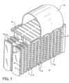
- Fig. 1 is an isometric view of a portion of a brazed heat exchanger.
- a brazed aluminium heat exchanger 2 in accordance with the present invention includes a plurality of fluid-carrying tubes 6.
- the ends of the fluid-carrying tubes 6 are open to a header plate 8 and a tank 10 (one end of the fluid-carrying tubes 6, one header plate 8 and one tank 10 are shown in Fig.1 ).
- Coolant is circulated from the tank 10, through the fluid-carrying tubes 6 and into another tank (not shown).
- a plurality of cooling fins 4 made from the rolled fin stock material according to this invention, are disposed between the fluid-carrying tubes 6, in order to transfer heat away therefrom thereby facilitating a heat exchange cooling the fluid therein.
Landscapes
- Engineering & Computer Science (AREA)
- Mechanical Engineering (AREA)
- Chemical & Material Sciences (AREA)
- Physics & Mathematics (AREA)
- Thermal Sciences (AREA)
- General Engineering & Computer Science (AREA)
- Materials Engineering (AREA)
- Metallurgy (AREA)
- Organic Chemistry (AREA)
- Crystallography & Structural Chemistry (AREA)
- Geometry (AREA)
- Metal Rolling (AREA)
- Continuous Casting (AREA)
- Laminated Bodies (AREA)
Description
- The invention relates to a rolled fin stock material from a 3xxx-series aluminium alloy comprising at least 1.3% to 2.0% Mn. The invention further relates to a brazed assembly of components incorporating such a fin stock material.
- As will be appreciated herein below, except as otherwise indicated, aluminium alloy designations and temper designations refer to the Aluminium Association designations in Aluminium Standards and Data and the Registration Records, as published by the Aluminium Association in 2018 and are well known to the person skilled in the art.
- For any description of alloy compositions or preferred alloy compositions, all references to percentages are by weight percent unless otherwise indicated.
- The term "up to" and "up to about", as employed herein, explicitly includes, but is not limited to, the possibility of zero weight-percent of the particular alloying element to which it refers. For example, up to about 0.3% Ni may include an alloy having no Ni.
- Heat exchangers and other similar equipment, such as condensers, evaporators and the like for use in car coolers, air conditioning systems, industrial cooling systems, etc. usually comprise a number of heat exchange tubes arranged in parallel between two headers, each tube joined at either end to one of the headers. Corrugated fins are disposed in an airflow clearance between adjacent heat exchange tubes and are brazed to the respective tubes.
- The fin material or fin stock material for brazed heat exchangers is typically fabricated from 3xxx-series aluminium alloys such as, for example AA3003 or AA3003 with a purposive addition of Zn up to 3%.
- The fin stock material is joined to the heat exchange tubes in a brazing operation employing an aluminium alloy brazing filler, most commonly made from an AA4xxx-series alloy. The brazing filler is typically present on the outer surface of the heat exchange tube, but also the use of a clad fin configuration alone is being employed.
- The most used brazing processes used on an industrial scale are vacuum brazing and controlled atmosphere brazing using a salt-based brazing flux material. A more recent development concerns controlled atmosphere brazing without the use of salt-based brazing flux material.
-
US patent no. 9,493,861-B1 -
US patent no. 9,714,799 -
CN-103060622-A discloses a method for producing fins for an automotive heat exchanger by continuous roll casting of an Al-Mn-Zn-Sc aluminium alloy, the aluminium alloy having 0.05-0.15% Sc, 0.44-0.58% Si, 0.45-0.55% Fe, 0.10-0.15% Cu, 1.05-1.25% Mn, <0.05% Mg, 1.40-1.60% Zn, <0.025% Cr, <0.045% Ni, <0.045% Ti, <0.045% Zr, and the balance aluminium. -
JP-2006-176852-A -
JP-2006-176850-A -
WO-2016/190409-A1 discloses a high-strength 6XXX-series aluminium alloy automotive sheet for panel components and automobile structural components, the aluminium alloy comprising, 0.3-1.5% Mg, 0.3-1.5% Si, and at least one transition element selected from the group consisting of 0.1-0.8% Mn, 0.04-0.20% Zr, 0.04-0.20% Cr, and 0.02-0.1% Sc, balance aluminium and unavoidable impurities, and wherein the sheet at mid-thickness has an average grain size of 100 micron or less, and dispersoid particles comprising the at least one transition element of a defined average equivalent circle diameter and density. - There is room for improvement in the art of aluminium alloy fin stock material for use in brazed heat exchangers and having a further improved sagging resistance.
- It is an object of the invention to provide a rolled aluminium alloy fin stock material for brazed heat exchangers having at least an improved sagging resistance.
- This and other objects and further advantages are met or exceeded by the present invention. The invention is defined in the appended claims.
- In accordance with the present invention it has been found that the rolled fin stock material has a high post-braze strength combined with excellent brazing performance in terms of a high sagging resistance and a very low susceptibility to liquid core penetration during brazing, as well as good forming properties in the as-delivered condition. In particular the sagging resistance at elevated temperature has been significantly improved due to the combined addition of Sc and Zr to the aluminium alloy
- The rolled fin stock material is mainly intended for thin fin applications in heat exchangers produced by CAB brazing but can also be produced by vacuum brazing.
- Mn is the most important alloying element in the fin stock material and contributes to both particle and solid solution strengthening. Furthermore, Mn in a controlled number of particles is beneficial to control the sagging resistance and sensitivity to liquid core penetration as these particles control the recrystallisation process during braze heating leading to the formation of large recrystallised grains. The Mn content is in the range of 1.3% to 2.0%. A more preferred upper limit for the Mn content is 1.85%.
- Si contributes combined with Mn to both particle and solid solution strengthening. This promotes high post-braze strength and sagging resistance. An insufficient Si content, for example of less than 0.4%, results in reduced strengthening while too much Si, for example more than 1.5%, results in decreased thermal conductivity and a reduced melting temperature undesirably affecting the heat exchanger during the brazing operations. A preferred lower limit for the Si content is 0.5%, and more preferably 0.65%. The upper limit for the Si content is 1.5%, preferably 1.2%, and most preferably 1.1%.
- Fe is present in all known commercially available aluminium alloys. With a too high Fe content among other things the formability of the material decreases and also the corrosion performance is decreasing. The admissible Fe content is up to 0.8% maximum, and more preferably up to 0.6% maximum. A practical Fe content is in the range of 0.15% to 0.45% and allows for a good compromise in desired properties of the fin stock material such as post-braze strength and sagging resistance, while the fin stock material can be manufactured without great difficulties at least in part from scrap materials.
- The fin stock material may have relatively high levels of Mn, Si and Fe without departing from the concept of the present invention. In particular when high solidification rates during casting, typically as obtained by continuous casting such as twin-roll casting, are applied in the manufacturing process of producing the fin stock material the relatively high levels of alloying elements can be employed resulting in an alloy strip substantially without coarse intermetallics. When applying continuous casting techniques to produce feedstock for the fin stock material clearly also the lower and middle end of the disclosed ranges can be applied. In casting processes like direct chill (DC) casting of slabs or billets the solidification rates are such that in industrial practice the Fe level commonly does not exceed 0.6%, the Mn level does not exceed 1.85%, and the Si level does not 1.2%, otherwise detrimental coarse intermetallics can be produced, such as for example, primary Fe-bearing intermetallics. The exact Si, Fe and Mn-contents are tuned based on the formability, strength, corrosion resistance and sag resistance requirements of the specific application.
- Together with the Mn and Si, the purposive addition of scandium (Sc) in combination with the Zr is an essential alloying element and the Sc is present in a range of 0.01% to 0.6% to arrive at improved sagging resistance at elevated temperatures. Also the strength properties in the post-braze condition at elevated temperatures are increased. A preferred lower limit for the Sc is 0.05%, and more preferably 0.12%, and more preferably 0.17%. A more preferred upper-limit is 0.4%, and more preferably 0.30%.
- The aluminium alloy should contain also at least Zr in a range of 0.02% to 0.40%. In an embodiment the upper-limit for the Zr-content is 0.30%, and more preferably 0.2%. A preferred lower-limit for the Zr-content is 0.06%, and more preferably 0.08%.
- Zr combines with Sc to form a dispersoid having a reduced lattice mismatch between the dispersoid and aluminium matrix, which results in an enhanced inhibition of recrystallisation and thus leading to a higher recrystallisation temperature. The combined Sc and Zr addition favours the formation of larger post-braze grains after recrystallisation during the brazing heat-up and thereby increasing the sagging resistance. The increase is significantly higher compared to the addition of solely Sc or solely Zr in a similar compositional range. In the aluminium alloy according to the invention there must be a combined addition of at least Sc and Zr in order to achieve the desired post-braze strength properties. In an embodiment the combined addition of Sc and Zr is at least 0.20%, and preferably at least 0.23%. In the better examples the combined addition of Sc and Zr is at least 0.25%.
- The addition of Mg increases the post-braze strength of the fin stock alloy significantly, but at too high levels it may increase the risk of incipient melting of phases in the fin stock material during the brazing operation. For controlled atmosphere brazing (CAB) higher Mg contents are not desired because of a potential poisoning effect on the brazing flux material. When employed in a vacuum brazing operation the Mg content in the fin stock alloy is much less critical and can be present up to 2%. The Mg content can be present up to 2%, preferably up to 0.5%, preferably up to 0.35%, and most preferably up to 0.10%.
- Cu can enhance the post-braze strength of the fin stock material, however, it can have a detrimental influence on the corrosion potential of the fin material. Cu may be tolerated up to 0.5%, this achieves advantages in the tolerance of this fin stock alloy for impurity elements and allows this alloy to be composed from large amounts of scrap material, such as discarded heat exchangers, but not limited to this example. A more preferred range for the Cu-level is up to 0.30%, and more preferably up to 0.20%, as a compromise in achieving post-braze strength, corrosion resistance and brazeability. If the corrosion resistance prevails as very important property for the use of the fin stock material in a certain heat exchanger application, then the Cu content is preferably kept at levels below 0.20%, and most preferably below 0.05%, for example at a level of not more than 0.01% or 0.02%.
- The alloying element zinc (Zn) affects the corrosion potential of the fin stock material and can be present up to 4%. By reducing the corrosion potential of the fin stock, Zn has the effect of causing the fins to function as sacrificial anodes, thereby providing corrosion protection for the tubes of the heat exchanger to which they are brazed. Zinc has a detectable, but relatively small effect on the strength and thermal conductivity. For this reason, a minimum amount of Zn required for cathodic protection of the tube is added; usually that will require at least 0.35% Zn, and more preferably at least 0.5%. More than 4% Zn will have an impact on the self-corrosion rate. However, in some instances, such higher Zn contents of up to 3% Zn might be desirable at the expense of thermal conductivity and self-corrosion properties. By using an adjustable Zn content in the fin, the difference in corrosion potential between tubes and fins can be chosen to an adequate level for each application. A preferred upper limit for the Zn content is 2.7%. In a particular embodiment, the upper limit for the Zn content is 1.9%.
- Ni has been shown to promote strength without a significant detrimental influence on thermal conductivity. It is known, however, to have a negative impact on the self-corrosion characteristics of the fin stock material. It is envisioned that up to 0.3% might be tolerated in some specific instances, however, in general, Ni should be kept to less than 0.05%, and preferably less than 0.03%.
- Cr can be added up to 0.3% as another dispersoid forming element.
- Ti may be present up to 0.3% to act in particular as a grain refining additive during the casting of an ingot of the fin stock material of the invention. Additional Ti may be added, for example due to their presence in scrap material, to increase the strength of the fin alloy by solubility hardening. The total amount of Ti present in the aluminium alloy should preferably not exceed 0.20%, but preferably is less than 0.10%.
- The balance is made by aluminium and incidental impurities and tolerable impurities, each up to 0.05% maximum and in total 0.25% maximum, and preferably in total not exceeding 0.15%.
- In a particular embodiment of the aluminium fin stock material it concerns a composition consisting of, in wt.%: Mn 1.3-2.0%, Si 0.4-1.5%, Zn up to 4%, Fe up to 0.8%, Zr 0.02-0.40%, Sc 0.01-0.6%, Ni up to 0.3%, Cu up to 0.5%, Mg up 2%, Cr up to 0.3%, Ti up to 0.3%, the balance aluminium and impurities each <0.05%, total <0.25%, and with preferred narrower compositional ranges as herein described and claimed.
- The rolled fin stock material can be manufactured using method of producing fin stock material known in the art, for example those disclosed is
US patent no. 9,493,861-B1 9,714,799-B2 - For the casting of the rolling feedstock a continuous casting technique, e.g. twin-belt casting or roll casting, is favoured over a direct chill (DC) type casting technique. The relative high cooling rate during a continuous casting operation provides a more favourable and fine distribution of dispersoid particles and other microstructural features resulting in the high required post-braze strength combined with an increased sagging resistance, in particular at elevated temperatures.
- In view of the presence for the Sc and Zr as alloying elements, to produce the optimum performance of the aluminium alloy as fin stock material, the homogenisation temperature and/or the pre-heat temperature prior to hot rolling is in the range of 300°C to 500°C, and more preferably in the range of 370°C to 480°C, to control the formation of small dispersoid particles. The soaking time is typically in a range of 1 to 50 hours.
- Following the homogenisation and/or pre-heat step, a hot rolling step can be performed. The hot-mill entry temperature is preferably in a range of 350°C and 470°C. The aluminium alloy is hot rolled to a gauge of 2 mm to 15 mm, and subsequently cold rolled to final gauge. Optionally, the rolled aluminium sheet can be annealed by heating the sheet from room temperature to an annealing temperature regular in the art to arrive at the required temper.
- In an embodiment the rolled fin stock material is provided with an aluminium alloy clad layer on one or both sides, using cladding layer thicknesses of 3% to 20%, preferably 3% to 15%, of the total thickness of the strip on each side. The aluminium alloy clad layer may be a 4xxx-series filler alloy typically having Si in a range of 5% to 14% as its main alloying constituent. Typical filler alloys within this series are AA4343, AA4045, AA4047, AA4004, AA4104, AA4047 and AA4147, or some near compositional variants thereof, or 4xxx alloys having a purposive addition of Zn up to 5%, as well as typical protective based on commercially pure aluminium alloys (e.g. AA1xxx-series). The aluminium alloy clad layer(s) is preferably applied by roll bonding as in well known in the art.
- In an embodiment the rolled fin stock material is provided in a bare form, thus devoid of any metallic layers, such as for example a 4xxx-series brazing clad layer, on its outer surface.
- At final gauge the rolled fin stock material is typically at a gauge in the range of 0.02 mm to 1.0 mm, preferably from 0.02 mm to 0.3 mm. A preferred lower-limit for the gauge is 0.03 mm. A preferred upper-limit for the gauge is 0.2 mm, more preferably 0.15 mm, and most preferably 0.10 mm.
- In the pre-braze condition the rolled fin stock material is typically provided in an H1x or H2x temper, wherein x has a value from 1 to 9, such as for example the H14, H18, H22, H24 and H26 temper.
- In an aspect of the invention there is provided in a brazed assembly, typically a heat exchanger, comprising the rolled fin stock material of the invention. In such a heat exchanger having the rolled fin stock material of the invention as corrugated fins, the fins may act as a sacrificial anode. The brazed heat exchanger typically comprises at least one tank structured to hold a coolant; a header plate coupled to said at least one tank, said header plate including a plurality of apertures; a plurality of substantially parallel fluid-carrying tubes each extending substantially perpendicular from one of said plurality of apertures in said header plate and structured to receive said coolant therethrough; and a plurality of fins, said fins being in thermal communication with said plurality of fluid-carrying tubes and structured to transfer heat away therefrom, in order to cool said coolant as it circulates therein, said plurality of fins being made from the rolled fin stock material as herein disclosed and claimed.
- The heat exchangers incorporating the rolled stock material according to this invention can be used widely in the transportation industries, such as the automotive industry, for powertrain cooling and HVAC&R applications, as well as for domestic and industrial cooling purposes, e.g. for fluid processing and HVAC&R applications.
-
Fig. 1 is an isometric view of a portion of a brazed heat exchanger. - As shown in
Fig. 1 , a brazed aluminium heat exchanger 2 in accordance with the present invention includes a plurality of fluid-carrying tubes 6. The ends of the fluid-carrying tubes 6 are open to a header plate 8 and a tank 10 (one end of the fluid-carrying tubes 6, one header plate 8 and onetank 10 are shown inFig.1 ). Coolant is circulated from thetank 10, through the fluid-carrying tubes 6 and into another tank (not shown). As shown, a plurality ofcooling fins 4, made from the rolled fin stock material according to this invention, are disposed between the fluid-carrying tubes 6, in order to transfer heat away therefrom thereby facilitating a heat exchange cooling the fluid therein.
Claims (15)
- A rolled fin stock material from an 3xxx-series aluminium alloy comprising, in wt.%,
Mn 1.3% to 2.0%, Si 0.4% to 1.5%, Zn up to 4%, preferably 0.35% to 3%, Fe up to 0.8%, Zr 0.02% to 0.40%, Sc 0.01% to 0.6%, Ni up to 0.3%, preferably less than 0.05%, Cu up to 0.5%, Mg up to 2%, Cr up to 0.3%, Ti up to 0.3%, - A rolled fin stock material according to claim 1, wherein the Sc content is at least 0.05%, and preferably at least 0.12%; and/or
wherein the Sc content is maximum 0.4%, and preferably maximum 0.30%. - A rolled fin stock material according to any one of claims 1 or 2, wherein the Zr content is at least 0.06%, and preferably at least 0.08%; and/or
wherein the Zr content is maximum 0.30%, and preferably maximum 0.20%. - A rolled fin stock material according to any one of claims 1 to 3,
wherein the Mn content is at most 1.85%. - A rolled fin stock material according to any one of claims 1 to 4, wherein the Cu content is maximum 0.30%, preferably maximum 0.20%, and more preferably maximum 0.05%.
- A rolled fin stock material according to any one of claims 1 to 5, wherein the Mg content is maximum 0.5%, preferably maximum 0.35%, and more preferably maximum 0.10%.
- A rolled fin stock material according to any one of claims 1 to 6, wherein the Zn content is at least 0.35%, and preferably at least 0.5%, and preferably up to 3%.
- A rolled fin stock material according to any one of claims 1 to 7, wherein a clad layer is applied on one or both sides of the rolled fin stock material.
- A rolled fin stock material according to any one of claims 1 to 7, wherein the rolled fin stock material is devoid of any metallic layer(s) applied on either side.
- A rolled fin stock material according to any one of claims 1 to 9, wherein the fin stock material at final gauge has a thickness of 0.02 mm to 0.3 mm, preferably 0.03 mm to 0.15 mm.
- A rolled fin stock material according to any one of claims 1 to 10, wherein the fin stock material in the pre-braze condition is provided in an H1x or H2x temper and wherein x is from 1 to 9.
- A rolled fin stock material according to any one of claims 1 to 11, wherein the fin stock material has been produced by a continuous casting operation.
- Method of manufacturing a rolled fin stock material according to any one of claims 1 to 12, comprising the steps of casting rolling feedstock, homogenising and/or pre-heating of the rolling feedstock at a temperature in a range of 300°C to 500°C, preferably in the range of 370°C to 480°C, prior to hot rolling to a gauge of 2 mm to 15 mm, cold rolling to final gauge, and optionally annealing of the cold rolled material at final gauge.
- A brazed assembly of components, comprising a plurality of substantially parallel fluid-carrying tubes and a plurality of fins; said fins being in thermal communication with said plurality of fluid-carrying tubes and structured to transfer heat away therefrom, said plurality of fins comprising a rolled fin stock material according to any one of claims 1 to 12.
- A brazed assembly of components according to claim 14, wherein the brazed assembly of components is a heat exchanger.
Applications Claiming Priority (2)
| Application Number | Priority Date | Filing Date | Title |
|---|---|---|---|
| EP18196278 | 2018-09-24 | ||
| PCT/EP2019/073661 WO2020064291A1 (en) | 2018-09-24 | 2019-09-05 | Aluminium alloy fin stock material |
Publications (2)
| Publication Number | Publication Date |
|---|---|
| EP3821048A1 EP3821048A1 (en) | 2021-05-19 |
| EP3821048B1 true EP3821048B1 (en) | 2024-07-24 |
Family
ID=63683067
Family Applications (1)
| Application Number | Title | Priority Date | Filing Date |
|---|---|---|---|
| EP19762165.9A Active EP3821048B1 (en) | 2018-09-24 | 2019-09-05 | Aluminium alloy fin stock material |
Country Status (7)
| Country | Link |
|---|---|
| US (1) | US20210310754A1 (en) |
| EP (1) | EP3821048B1 (en) |
| CN (1) | CN112752856A (en) |
| ES (1) | ES2986885T3 (en) |
| HU (1) | HUE068196T2 (en) |
| PL (1) | PL3821048T3 (en) |
| WO (1) | WO2020064291A1 (en) |
Families Citing this family (4)
| Publication number | Priority date | Publication date | Assignee | Title |
|---|---|---|---|---|
| CN112195375B (en) * | 2020-10-16 | 2022-04-12 | 江苏常铝铝业集团股份有限公司 | Self-brazing aluminum alloy foil and manufacturing method thereof |
| CN113201672B (en) * | 2021-04-20 | 2022-06-14 | 北京科技大学 | A kind of Al-Mg-Si-Cu-Zn alloy with high baking paint hardening increment and preparation method thereof |
| CN115948681B (en) * | 2022-12-21 | 2024-04-16 | 广东兴发铝业有限公司 | Aluminum profile for relieved tooth radiator and extrusion production method thereof |
| WO2025137216A1 (en) * | 2023-12-19 | 2025-06-26 | Novelis Inc. | High magnesium content aluminum alloy products including oxide coating for controlled atmosphere brazing |
Family Cites Families (16)
| Publication number | Priority date | Publication date | Assignee | Title |
|---|---|---|---|---|
| JP2000026931A (en) * | 1998-05-01 | 2000-01-25 | Mitsubishi Alum Co Ltd | Aluminum alloy brazing sheet for formation of brazed tube, and brazed tube |
| FR2816534B1 (en) * | 2000-11-16 | 2003-01-31 | Pechiney Rhenalu | PROCESS FOR MANUFACTURING AN ALUMINUM ALLOY PLATED STRIP FOR THE MANUFACTURE OF BRAZED HEAT EXCHANGERS |
| NO20016355D0 (en) * | 2001-12-21 | 2001-12-21 | Norsk Hydro As | Aluminum heat sink with improved strength and durability |
| SE0203009D0 (en) * | 2002-10-14 | 2002-10-14 | Sapa Heat Transfer Ab | High strenth aluminum fine material for brazing |
| AT413035B (en) * | 2003-11-10 | 2005-10-15 | Arc Leichtmetallkompetenzzentrum Ranshofen Gmbh | ALUMINUM ALLOY |
| JP2006176852A (en) * | 2004-12-24 | 2006-07-06 | Mitsubishi Alum Co Ltd | High-strength aluminum alloy cladding material for heat exchanger having excellent erosion resistance, heat exchanger and method for producing high-strength aluminum alloy cladding material |
| JP4566729B2 (en) * | 2004-12-24 | 2010-10-20 | 三菱アルミニウム株式会社 | High strength aluminum alloy fin material and heat exchanger for heat exchanger with excellent erosion resistance |
| SE530437C2 (en) * | 2006-10-13 | 2008-06-03 | Sapa Heat Transfer Ab | Rank material with high strength and high sagging resistance |
| SE533287C2 (en) * | 2008-04-18 | 2010-08-10 | Sapa Heat Transfer Ab | Sandwich material for soldering with high strength at high temperature |
| PL2699702T3 (en) * | 2011-04-20 | 2018-10-31 | Aleris Rolled Products Germany Gmbh | Fin stock material |
| US9433996B2 (en) * | 2011-04-25 | 2016-09-06 | Mahle International Gmbh | Method of making a heat exchanger with an enhanced material system |
| US20140130637A1 (en) * | 2012-04-16 | 2014-05-15 | Chung-Shan Institute of Science and Technology, Armaments, Bureau, Ministry of National Defense | Method for Making a Strong Aluminum Alloy |
| KR102045789B1 (en) * | 2012-05-23 | 2019-11-18 | 그랑게스 스웨덴 아베 | Ultra sagging and melting resistant fin material with very high strength |
| CN103060622B (en) | 2012-12-31 | 2015-06-10 | 江阴新仁科技有限公司 | Method for producing Al-Mn-Zn-Sc aluminum alloy foil for automobile radiating fin by continuous roll casting |
| CN106282696A (en) * | 2015-05-19 | 2017-01-04 | 沈阳万龙源冶金新材料科技有限公司 | A kind of high-strength/tenacity aluminum alloy |
| JP6810508B2 (en) | 2015-05-28 | 2021-01-06 | 株式会社神戸製鋼所 | High-strength aluminum alloy plate |
-
2019
- 2019-09-05 EP EP19762165.9A patent/EP3821048B1/en active Active
- 2019-09-05 PL PL19762165.9T patent/PL3821048T3/en unknown
- 2019-09-05 HU HUE19762165A patent/HUE068196T2/en unknown
- 2019-09-05 WO PCT/EP2019/073661 patent/WO2020064291A1/en not_active Ceased
- 2019-09-05 CN CN201980062339.5A patent/CN112752856A/en active Pending
- 2019-09-05 ES ES19762165T patent/ES2986885T3/en active Active
- 2019-09-05 US US17/250,786 patent/US20210310754A1/en not_active Abandoned
Also Published As
| Publication number | Publication date |
|---|---|
| WO2020064291A1 (en) | 2020-04-02 |
| CN112752856A (en) | 2021-05-04 |
| PL3821048T3 (en) | 2024-10-28 |
| US20210310754A1 (en) | 2021-10-07 |
| ES2986885T3 (en) | 2024-11-13 |
| HUE068196T2 (en) | 2024-12-28 |
| EP3821048A1 (en) | 2021-05-19 |
Similar Documents
| Publication | Publication Date | Title |
|---|---|---|
| EP3423607B1 (en) | Rolled aluminium alloy for heat exchangers | |
| EP1323839B1 (en) | Aluminium brazing alloy | |
| US6352789B1 (en) | Brazing sheet and method of making same | |
| US5125452A (en) | Aluminum alloy clad material | |
| EP3797034B1 (en) | Brazed heat exchanger | |
| US9377249B2 (en) | Fin stock material | |
| WO2007131727A1 (en) | Method of producing a clad aluminum alloy sheet for brazing purposes and sheet produced by said method | |
| US20210310754A1 (en) | Aluminium alloy fin stock material | |
| US6610247B2 (en) | Aluminum brazing alloy | |
| US6800244B2 (en) | Aluminum brazing alloy | |
| EP4143356B1 (en) | Aluminium alloy sheet material and heat exchanger incorporating such an aluminium alloy sheet material |
Legal Events
| Date | Code | Title | Description |
|---|---|---|---|
| STAA | Information on the status of an ep patent application or granted ep patent |
Free format text: STATUS: UNKNOWN |
|
| STAA | Information on the status of an ep patent application or granted ep patent |
Free format text: STATUS: THE INTERNATIONAL PUBLICATION HAS BEEN MADE |
|
| TPAC | Observations filed by third parties |
Free format text: ORIGINAL CODE: EPIDOSNTIPA |
|
| PUAI | Public reference made under article 153(3) epc to a published international application that has entered the european phase |
Free format text: ORIGINAL CODE: 0009012 |
|
| STAA | Information on the status of an ep patent application or granted ep patent |
Free format text: STATUS: REQUEST FOR EXAMINATION WAS MADE |
|
| 17P | Request for examination filed |
Effective date: 20210209 |
|
| AK | Designated contracting states |
Kind code of ref document: A1 Designated state(s): AL AT BE BG CH CY CZ DE DK EE ES FI FR GB GR HR HU IE IS IT LI LT LU LV MC MK MT NL NO PL PT RO RS SE SI SK SM TR |
|
| STAA | Information on the status of an ep patent application or granted ep patent |
Free format text: STATUS: EXAMINATION IS IN PROGRESS |
|
| DAV | Request for validation of the european patent (deleted) | ||
| DAX | Request for extension of the european patent (deleted) | ||
| 17Q | First examination report despatched |
Effective date: 20211209 |
|
| RAP3 | Party data changed (applicant data changed or rights of an application transferred) |
Owner name: NOVELIS KOBLENZ GMBH |
|
| GRAP | Despatch of communication of intention to grant a patent |
Free format text: ORIGINAL CODE: EPIDOSNIGR1 |
|
| STAA | Information on the status of an ep patent application or granted ep patent |
Free format text: STATUS: GRANT OF PATENT IS INTENDED |
|
| INTG | Intention to grant announced |
Effective date: 20240222 |
|
| GRAS | Grant fee paid |
Free format text: ORIGINAL CODE: EPIDOSNIGR3 |
|
| GRAA | (expected) grant |
Free format text: ORIGINAL CODE: 0009210 |
|
| STAA | Information on the status of an ep patent application or granted ep patent |
Free format text: STATUS: THE PATENT HAS BEEN GRANTED |
|
| AK | Designated contracting states |
Kind code of ref document: B1 Designated state(s): AL AT BE BG CH CY CZ DE DK EE ES FI FR GB GR HR HU IE IS IT LI LT LU LV MC MK MT NL NO PL PT RO RS SE SI SK SM TR |
|
| REG | Reference to a national code |
Ref country code: GB Ref legal event code: FG4D |
|
| REG | Reference to a national code |
Ref country code: CH Ref legal event code: EP |
|
| REG | Reference to a national code |
Ref country code: IE Ref legal event code: FG4D Ref country code: DE Ref legal event code: R096 Ref document number: 602019055738 Country of ref document: DE |
|
| P01 | Opt-out of the competence of the unified patent court (upc) registered |
Free format text: CASE NUMBER: APP_43764/2024 Effective date: 20240726 |
|
| REG | Reference to a national code |
Ref country code: NL Ref legal event code: FP |
|
| PGFP | Annual fee paid to national office [announced via postgrant information from national office to epo] |
Ref country code: NL Payment date: 20240820 Year of fee payment: 6 |
|
| REG | Reference to a national code |
Ref country code: SE Ref legal event code: TRGR |
|
| PGFP | Annual fee paid to national office [announced via postgrant information from national office to epo] |
Ref country code: DE Payment date: 20240820 Year of fee payment: 6 |
|
| PGFP | Annual fee paid to national office [announced via postgrant information from national office to epo] |
Ref country code: GB Payment date: 20240820 Year of fee payment: 6 |
|
| PGFP | Annual fee paid to national office [announced via postgrant information from national office to epo] |
Ref country code: BE Payment date: 20240820 Year of fee payment: 6 |
|
| PGFP | Annual fee paid to national office [announced via postgrant information from national office to epo] |
Ref country code: FR Payment date: 20240820 Year of fee payment: 6 |
|
| PGFP | Annual fee paid to national office [announced via postgrant information from national office to epo] |
Ref country code: CZ Payment date: 20240820 Year of fee payment: 6 |
|
| PGFP | Annual fee paid to national office [announced via postgrant information from national office to epo] |
Ref country code: AT Payment date: 20240821 Year of fee payment: 6 |
|
| PGFP | Annual fee paid to national office [announced via postgrant information from national office to epo] |
Ref country code: HU Payment date: 20240909 Year of fee payment: 6 |
|
| PGFP | Annual fee paid to national office [announced via postgrant information from national office to epo] |
Ref country code: RO Payment date: 20240905 Year of fee payment: 6 Ref country code: NO Payment date: 20240821 Year of fee payment: 6 Ref country code: SE Payment date: 20240820 Year of fee payment: 6 |
|
| REG | Reference to a national code |
Ref country code: LT Ref legal event code: MG9D |
|
| REG | Reference to a national code |
Ref country code: ES Ref legal event code: FG2A Ref document number: 2986885 Country of ref document: ES Kind code of ref document: T3 Effective date: 20241113 |
|
| REG | Reference to a national code |
Ref country code: GR Ref legal event code: EP Ref document number: 20240402288 Country of ref document: GR Effective date: 20241111 |
|
| PG25 | Lapsed in a contracting state [announced via postgrant information from national office to epo] |
Ref country code: PT Free format text: LAPSE BECAUSE OF FAILURE TO SUBMIT A TRANSLATION OF THE DESCRIPTION OR TO PAY THE FEE WITHIN THE PRESCRIBED TIME-LIMIT Effective date: 20241125 |
|
| REG | Reference to a national code |
Ref country code: AT Ref legal event code: UEP Ref document number: 1706382 Country of ref document: AT Kind code of ref document: T Effective date: 20240724 |
|
| REG | Reference to a national code |
Ref country code: HU Ref legal event code: AG4A Ref document number: E068196 Country of ref document: HU |
|
| PG25 | Lapsed in a contracting state [announced via postgrant information from national office to epo] |
Ref country code: PT Free format text: LAPSE BECAUSE OF FAILURE TO SUBMIT A TRANSLATION OF THE DESCRIPTION OR TO PAY THE FEE WITHIN THE PRESCRIBED TIME-LIMIT Effective date: 20241125 |
|
| PG25 | Lapsed in a contracting state [announced via postgrant information from national office to epo] |
Ref country code: FI Free format text: LAPSE BECAUSE OF FAILURE TO SUBMIT A TRANSLATION OF THE DESCRIPTION OR TO PAY THE FEE WITHIN THE PRESCRIBED TIME-LIMIT Effective date: 20240724 |
|
| PGFP | Annual fee paid to national office [announced via postgrant information from national office to epo] |
Ref country code: PL Payment date: 20240821 Year of fee payment: 6 Ref country code: GR Payment date: 20241017 Year of fee payment: 6 |
|
| PG25 | Lapsed in a contracting state [announced via postgrant information from national office to epo] |
Ref country code: BG Free format text: LAPSE BECAUSE OF FAILURE TO SUBMIT A TRANSLATION OF THE DESCRIPTION OR TO PAY THE FEE WITHIN THE PRESCRIBED TIME-LIMIT Effective date: 20240724 |
|
| PG25 | Lapsed in a contracting state [announced via postgrant information from national office to epo] |
Ref country code: LV Free format text: LAPSE BECAUSE OF FAILURE TO SUBMIT A TRANSLATION OF THE DESCRIPTION OR TO PAY THE FEE WITHIN THE PRESCRIBED TIME-LIMIT Effective date: 20240724 |
|
| PG25 | Lapsed in a contracting state [announced via postgrant information from national office to epo] |
Ref country code: IS Free format text: LAPSE BECAUSE OF FAILURE TO SUBMIT A TRANSLATION OF THE DESCRIPTION OR TO PAY THE FEE WITHIN THE PRESCRIBED TIME-LIMIT Effective date: 20241124 |
|
| PG25 | Lapsed in a contracting state [announced via postgrant information from national office to epo] |
Ref country code: HR Free format text: LAPSE BECAUSE OF FAILURE TO SUBMIT A TRANSLATION OF THE DESCRIPTION OR TO PAY THE FEE WITHIN THE PRESCRIBED TIME-LIMIT Effective date: 20240724 |
|
| PG25 | Lapsed in a contracting state [announced via postgrant information from national office to epo] |
Ref country code: RS Free format text: LAPSE BECAUSE OF FAILURE TO SUBMIT A TRANSLATION OF THE DESCRIPTION OR TO PAY THE FEE WITHIN THE PRESCRIBED TIME-LIMIT Effective date: 20241024 |
|
| PGFP | Annual fee paid to national office [announced via postgrant information from national office to epo] |
Ref country code: ES Payment date: 20241001 Year of fee payment: 6 |
|
| PG25 | Lapsed in a contracting state [announced via postgrant information from national office to epo] |
Ref country code: RS Free format text: LAPSE BECAUSE OF FAILURE TO SUBMIT A TRANSLATION OF THE DESCRIPTION OR TO PAY THE FEE WITHIN THE PRESCRIBED TIME-LIMIT Effective date: 20241024 Ref country code: LV Free format text: LAPSE BECAUSE OF FAILURE TO SUBMIT A TRANSLATION OF THE DESCRIPTION OR TO PAY THE FEE WITHIN THE PRESCRIBED TIME-LIMIT Effective date: 20240724 Ref country code: IS Free format text: LAPSE BECAUSE OF FAILURE TO SUBMIT A TRANSLATION OF THE DESCRIPTION OR TO PAY THE FEE WITHIN THE PRESCRIBED TIME-LIMIT Effective date: 20241124 Ref country code: HR Free format text: LAPSE BECAUSE OF FAILURE TO SUBMIT A TRANSLATION OF THE DESCRIPTION OR TO PAY THE FEE WITHIN THE PRESCRIBED TIME-LIMIT Effective date: 20240724 Ref country code: FI Free format text: LAPSE BECAUSE OF FAILURE TO SUBMIT A TRANSLATION OF THE DESCRIPTION OR TO PAY THE FEE WITHIN THE PRESCRIBED TIME-LIMIT Effective date: 20240724 Ref country code: BG Free format text: LAPSE BECAUSE OF FAILURE TO SUBMIT A TRANSLATION OF THE DESCRIPTION OR TO PAY THE FEE WITHIN THE PRESCRIBED TIME-LIMIT Effective date: 20240724 |
|
| PGFP | Annual fee paid to national office [announced via postgrant information from national office to epo] |
Ref country code: CH Payment date: 20241001 Year of fee payment: 6 |
|
| PGFP | Annual fee paid to national office [announced via postgrant information from national office to epo] |
Ref country code: TR Payment date: 20241002 Year of fee payment: 6 |
|
| PG25 | Lapsed in a contracting state [announced via postgrant information from national office to epo] |
Ref country code: SM Free format text: LAPSE BECAUSE OF FAILURE TO SUBMIT A TRANSLATION OF THE DESCRIPTION OR TO PAY THE FEE WITHIN THE PRESCRIBED TIME-LIMIT Effective date: 20240724 Ref country code: DK Free format text: LAPSE BECAUSE OF FAILURE TO SUBMIT A TRANSLATION OF THE DESCRIPTION OR TO PAY THE FEE WITHIN THE PRESCRIBED TIME-LIMIT Effective date: 20240724 |
|
| PG25 | Lapsed in a contracting state [announced via postgrant information from national office to epo] |
Ref country code: EE Free format text: LAPSE BECAUSE OF FAILURE TO SUBMIT A TRANSLATION OF THE DESCRIPTION OR TO PAY THE FEE WITHIN THE PRESCRIBED TIME-LIMIT Effective date: 20240724 Ref country code: MC Free format text: LAPSE BECAUSE OF FAILURE TO SUBMIT A TRANSLATION OF THE DESCRIPTION OR TO PAY THE FEE WITHIN THE PRESCRIBED TIME-LIMIT Effective date: 20240724 |
|
| REG | Reference to a national code |
Ref country code: DE Ref legal event code: R097 Ref document number: 602019055738 Country of ref document: DE |
|
| PG25 | Lapsed in a contracting state [announced via postgrant information from national office to epo] |
Ref country code: SK Free format text: LAPSE BECAUSE OF FAILURE TO SUBMIT A TRANSLATION OF THE DESCRIPTION OR TO PAY THE FEE WITHIN THE PRESCRIBED TIME-LIMIT Effective date: 20240724 |
|
| PG25 | Lapsed in a contracting state [announced via postgrant information from national office to epo] |
Ref country code: LU Free format text: LAPSE BECAUSE OF NON-PAYMENT OF DUE FEES Effective date: 20240905 |
|
| PLBE | No opposition filed within time limit |
Free format text: ORIGINAL CODE: 0009261 |
|
| STAA | Information on the status of an ep patent application or granted ep patent |
Free format text: STATUS: NO OPPOSITION FILED WITHIN TIME LIMIT |
|
| 26N | No opposition filed |
Effective date: 20250425 |
|
| PG25 | Lapsed in a contracting state [announced via postgrant information from national office to epo] |
Ref country code: IT Free format text: LAPSE BECAUSE OF NON-PAYMENT OF DUE FEES Effective date: 20240905 |
|
| PG25 | Lapsed in a contracting state [announced via postgrant information from national office to epo] |
Ref country code: IE Free format text: LAPSE BECAUSE OF NON-PAYMENT OF DUE FEES Effective date: 20240905 |
|
| PG25 | Lapsed in a contracting state [announced via postgrant information from national office to epo] |
Ref country code: CY Free format text: LAPSE BECAUSE OF FAILURE TO SUBMIT A TRANSLATION OF THE DESCRIPTION OR TO PAY THE FEE WITHIN THE PRESCRIBED TIME-LIMIT; INVALID AB INITIO Effective date: 20190905 |
|
| PG25 | Lapsed in a contracting state [announced via postgrant information from national office to epo] |
Ref country code: RO Free format text: LAPSE BECAUSE OF NON-PAYMENT OF DUE FEES Effective date: 20250905 |
|
| PG25 | Lapsed in a contracting state [announced via postgrant information from national office to epo] |
Ref country code: CZ Free format text: LAPSE BECAUSE OF NON-PAYMENT OF DUE FEES Effective date: 20250905 |
|
| REG | Reference to a national code |
Ref country code: CH Ref legal event code: H13 Free format text: ST27 STATUS EVENT CODE: U-0-0-H10-H13 (AS PROVIDED BY THE NATIONAL OFFICE) Effective date: 20260504 |
|
| REG | Reference to a national code |
Ref country code: NL Ref legal event code: MM Effective date: 20251001 |