EP3820764B1 - Deflector arrangement for a tracked vehicle - Google Patents
Deflector arrangement for a tracked vehicle Download PDFInfo
- Publication number
- EP3820764B1 EP3820764B1 EP19833632.3A EP19833632A EP3820764B1 EP 3820764 B1 EP3820764 B1 EP 3820764B1 EP 19833632 A EP19833632 A EP 19833632A EP 3820764 B1 EP3820764 B1 EP 3820764B1
- Authority
- EP
- European Patent Office
- Prior art keywords
- wheel
- arrangement
- deflector arrangement
- deflector
- track
- Prior art date
- Legal status (The legal status is an assumption and is not a legal conclusion. Google has not performed a legal analysis and makes no representation as to the accuracy of the status listed.)
- Active
Links
Images
Classifications
-
- B—PERFORMING OPERATIONS; TRANSPORTING
- B62—LAND VEHICLES FOR TRAVELLING OTHERWISE THAN ON RAILS
- B62D—MOTOR VEHICLES; TRAILERS
- B62D55/00—Endless track vehicles
- B62D55/08—Endless track units; Parts thereof
- B62D55/088—Endless track units; Parts thereof with means to exclude or remove foreign matter, e.g. sealing means, self-cleaning track links or sprockets, deflector plates or scrapers
-
- B—PERFORMING OPERATIONS; TRANSPORTING
- B62—LAND VEHICLES FOR TRAVELLING OTHERWISE THAN ON RAILS
- B62D—MOTOR VEHICLES; TRAILERS
- B62D55/00—Endless track vehicles
- B62D55/08—Endless track units; Parts thereof
- B62D55/084—Endless-track units or carriages mounted separably, adjustably or extensibly on vehicles, e.g. portable track units
- B62D55/0845—Protection devices
-
- B—PERFORMING OPERATIONS; TRANSPORTING
- B62—LAND VEHICLES FOR TRAVELLING OTHERWISE THAN ON RAILS
- B62D—MOTOR VEHICLES; TRAILERS
- B62D55/00—Endless track vehicles
- B62D55/06—Endless track vehicles with tracks without ground wheels
-
- B—PERFORMING OPERATIONS; TRANSPORTING
- B62—LAND VEHICLES FOR TRAVELLING OTHERWISE THAN ON RAILS
- B62D—MOTOR VEHICLES; TRAILERS
- B62D55/00—Endless track vehicles
- B62D55/08—Endless track units; Parts thereof
- B62D55/104—Suspension devices for wheels, rollers, bogies or frames
-
- B—PERFORMING OPERATIONS; TRANSPORTING
- B62—LAND VEHICLES FOR TRAVELLING OTHERWISE THAN ON RAILS
- B62D—MOTOR VEHICLES; TRAILERS
- B62D55/00—Endless track vehicles
- B62D55/08—Endless track units; Parts thereof
- B62D55/104—Suspension devices for wheels, rollers, bogies or frames
- B62D55/108—Suspension devices for wheels, rollers, bogies or frames with mechanical springs, e.g. torsion bars
Definitions
- the present invention relates to a deflector arrangement for a tracked vehicle.
- the present invention relates to a tracked vehicle.
- Tracked vehicles normally comprise a pair of track assemblies, where each track assembly of the pair of track assemblies comprises a front drive wheel, a rear tension wheel and a plurality of road wheels there between.
- the respective track assembly further comprises an endless track running over the drive wheel, the plurality of support wheels and the tensions wheel. Said drive wheel and said plurality of support wheels are rotatably secured to the vehicle body of the vehicle.
- Such tracked vehicles e.g. combat vehicles
- a problem during drive in rough terrain with such vehicle is that ingestion of undesired material such as gravel and stones into the respective track assembly and in between wheels and the endless track may occur which in turn cause damages to the tracked vehicle and in some cases may result in the endless track being torn apart.
- US2637603A discloses a muck stripper for endless track treads for use in connection with drive sprockets, the stripper being arranged to prevent foreign material from being carried around the sprocket during operation of the endless track tread.
- US2008150355A1 discloses a deflector for reducing the ingestion of snow and/or other debris in one of the sprocket wheel and idler wheel area of a vehicle equipped with endless tracks.
- US20050046277A1 discloses a tracked vehicle comprising a cutter bar provided for trimming debris away from the wheel-track interface of the tracked vehicle.
- a pivot attachment is provided wherein a knife having a cutting edge is removably mounted to a bracket by way of fasteners which will shear when a pre-selected force is applied to them.
- the bracket is mounted to the vehicle structure so that the knife is disposed in close proximity to the drive wheel and endless track of the vehicle.
- SU 1751035A1 discloses a track-cleaning device of a tracked vehicle.
- GB2357066A discloses a tractor with an apparatus for protecting a track assembly of the tractor.
- the track tractor includes a protection member secured to a frame of the track assembly such that a portion of the frame is positioned behind the protection member.
- the tractor further includes a number of first guard members secured to the first protection member so that (i) the guard members extend downwardly beyond the first lower edge toward the endless track of the track assembly and (ii) the first guard members are spaced apart from each other along the lower edge such that a gap is defined between adjacent guard members.
- An object of the present invention is to provide a deflector arrangement for a tracked vehicle, which efficiently reduces ingestion of undesired material from the ground into said track assembly and facilitates removal of such undesired material from said track assembly.
- a further object of the present invention is to provide a tracked vehicle comprising such a deflector arrangement.
- a deflector arrangement for a tracked vehicle.
- Said tracked vehicle comprises at least one track assembly comprising two end wheels in the form of a front wheel and a rear wheel, and further a plurality of road wheels there between. At least one of the front wheel and rear wheel is a drive wheel and at least one of the front wheel and rear wheel is a tension wheel.
- the track assembly further comprises an endless track, said endless track being disposed around said end wheels and plurality of road wheels.
- Said deflector arrangement is configured to reduce ingestion of undesired material from the ground into said track assembly and removal of such undesired material from said track assembly.
- Said deflector arrangement is associated with an end wheel and is resiliently suspended and biasedly arranged so as to strive towards the inner surface of the endless track.
- Said deflector arrangement comprises a support wheel arrangement configured to roll against the inner surface of said endless track during movement of said vehicle.
- the deflector arrangement may, due to the deflector arrangement being resiliently suspended, handle any movements of the endless track.
- the deflector arrangement may, due to the deflector arrangement being resiliently suspended, withstand high loads during vehicle operation.
- the deflector arrangement may, due to the deflector arrangement being resiliently suspended, withstand being tilted due to side forces in connection to the deflector arrangement.
- Said deflector arrangement may according to an embodiment be suspended with respect to an end wheel or a road wheel adjacent to that end wheel. Said deflector arrangement may be thus resiliently suspended and biasedly arranged so as to strive towards the inner surface of the endless track by means of a force.
- said deflector arrangement is coaxially suspended with respect to the axis of an end wheel or a road wheel adjacent to that end wheel.
- the deflector arrangement may be efficiently and easily resiliently suspended and biased.
- said deflector arrangement comprises a plough arrangement being arranged between said end wheel and adjacent road wheel and configured to prevent such undesired material to be carried by said endless track around said end wheel.
- a plough arrangement being arranged between said end wheel and adjacent road wheel and configured to prevent such undesired material to be carried by said endless track around said end wheel.
- said deflector arrangement comprises a support wheel arrangement configured to roll against the inner surface of said endless track during movement of said vehicle.
- operation of the deflector arrangement is further improved in that the deflector arrangement due to the support wheel arrangement is allowed to roll freely relative to the endless track when the deflector arrangement strives towards the inner surface of the endless track.
- the risk of the deflector arrangement being damaged is, due to the thus provided support wheel arrangement, reduced.
- said support wheel arrangement is arranged in connection to the plough arrangement.
- operation of the deflector arrangement is further improved in that the deflector arrangement due to the support wheel arrangement arranged in connection to the plough arrangement is allowed to roll freely relative to the endless track when the deflector arrangement strives towards the inner surface of the endless track.
- the risk of the deflector arrangement being damaged is, due to the thus provided support wheel arrangement, reduced.
- said plough arrangement comprises a first plough member configured to be arranged on the outer side of the track assembly and a second plough member configured to be arranged on the inner side of the track assembly.
- said deflector arrangement comprises first and second laterally disposed shield elements configured to protect the wheel to which it is coaxially suspended on the respective side of the wheel.
- first and second laterally disposed shield elements configured to protect the wheel to which it is coaxially suspended on the respective side of the wheel.
- said deflector arrangement is coaxially suspended to the hub of said axis, wherein each plough member is attached to said hub via said laterally disposed shield element.
- the deflector arrangement is resiliently suspended and biasedly arranged by means of a spring arrangement.
- the spring arrangement comprises bushings and/or a torsion spring arrangement arranged in connection to said hub of said axis.
- efficient resilience of the resiliently suspended deflector arrangement is obtained.
- efficient biasing of the biasedly arranged deflector arrangement is facilitated.
- the bushings may according to an embodiment be rubber bushings. Such bushings further facilitates for the deflector arrangement to withstand being tilted due to side forces in connection to the deflector arrangement.
- a tracked vehicle comprising at least one deflector arrangement as set out herein.
- said tracked vehicle comprises a left track assembly, a right track assembly and a vehicle body, wherein said track assemblies are suspendedly arranged to said vehicle body via said road wheels by means of a suspension system, each track assembly comprising at least one deflector arrangement.
- the tracked vehicle according to the present disclosure may be any suitable tracked vehicle.
- the tracked vehicle according to the present disclosure may comprise at least one track assembly comprising two end wheels in the form of a front wheel and a rear wheel, and further a plurality of road wheels there between.
- at least one of the front wheel and rear wheel may be a drive wheel and at least one of the front wheel and rear wheel may be a tension wheel.
- the track assembly further comprises an endless track, said endless track being disposed around said end wheels and plurality of road wheels.
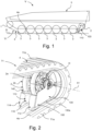
- Fig. 1 schematically illustrates a side view of a tracked vehicle V according to an embodiment of the present disclosure.
- the tracked vehicle V is driving on a ground G.
- the tracked vehicle V is a motor vehicle.
- the exemplified tracked vehicle V is constituted by a military tracked vehicle.
- the tracked vehicle V comprises a track assembly pair comprising two track assemblies, a left track assembly T1 and a right track assembly, the left track assembly T1 being shown in fig. 1 .
- the respective track assembly here illustrated with the left track assembly T1
- the front wheel 1 is a drive wheel 1
- the rear wheel 2 is a tension wheel 2.
- the track assembly further comprises an endless track 4, said endless track 4 being disposed around said end wheels 1, 2 and plurality of road wheels 3.
- the endless track 4 is thus configured to run around the drive wheel 1, tension wheel 2 and plurality of road wheels 3.
- the endless track 4 is a propulsion track 4 running around said wheels 1, 2, 3 for driving the vehicle V.
- the endless track 4 has an inner side with an inner surface 4a, which at least partly is in contact with the wheels 1, 2, 3 when the endless track is running around the wheels 1, 2, 3.
- the drive wheel 1 is configured to be operated by any suitable drive means such as an internal combustion engine and or/or an electric motor.
- the drive wheel 1 is configured to be rotated by the drive means for rotating the endless track for driving the vehicle.
- the respective drive wheel of the vehicle V is configured to be rotated by the drive means.
- vehicle body 5 which may include the chassis of the vehicle and bodywork.
- the vehicle V comprises a suspension system comprising a suspension device for the respective track assembly.
- the respective track assembly of the vehicle V is thus arranged to be supported by the vehicle body 5 by means of said suspension device.
- the road wheels 3 of the respective track assembly of the vehicle V is arranged to be supported by the vehicle body 5 by means of said suspension device.
- movability and comfort of the vehicle V is improved in that the vehicle body 5 is allowed to be raised and lowered relative to the track assembly.
- the suspension device is described in more detail with reference to fig. 5 .
- the vehicle V comprises a deflector arrangement 100 for the respective track assembly.
- the deflector arrangement 100 is configured to reduce ingestion of undesired material from the ground G into said track assembly T1 and removal of such undesired material from said track assembly T1.
- Said deflector arrangement 100 is associated with the tension wheel 2 and is resiliently suspended and biasedly arranged so as to strive towards the inner surface 4a of the endless track 4.
- the deflector arrangement 100 is coaxially suspended with respect to the axis of the tension wheel 2.
- the deflector arrangement comprises a plough arrangement 110 being arranged between said tension wheel 2 and adjacent road wheel 3 and configured to prevent such undesired material to be carried by said endless track around said tension wheel 2.
- Said deflector arrangement 100 is suspended with respect to the tension wheel 2 and is resiliently suspended and biasedly arranged so as to strive towards the inner surface 4a of the endless track 4 by means of a force F.
- Said deflector arrangement 100 is coaxially suspended with respect to the axis of the tension wheel 2 and is resiliently suspended and biasedly arranged so as to strive towards the inner surface 4a of the endless track 4 by means of a force F.
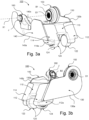
- Fig. 2 schematically illustrates a perspective view of a deflector arrangement 100 according to an embodiment of the present disclosure, arranged in connection to a tension wheel 2 of a tracked vehicle; and fig. 3a. and 3b schematically illustrate different perspective views of the deflector arrangement 100 in fig. 2 .
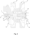
- Fig. 4 schematically illustrates a cross sectional view of the tension wheel 2 in connection to which the deflector arrangement 100 according to the present disclosure is configured to be arranged.
- Fig. 2 thus shows a portion of the left track assembly T1.
- the track assembly T1 has an outer side T1a configured to face away from the vehicle and an inner side T1b configured to face the vehicle body, as shown in fig. 5 .
- Fig. 2 schematically illustrates a perspective view of a portion of the track assembly T1 showing the outer side T1a of the track assembly, i.e. the side of the track assembly facing away from the vehicle body.
- the side of the tension wheel 2 facing away from the vehicle body is shown in fig. 2 .
- the deflector arrangement 100 is configured to reduce ingestion of undesired material from the ground into said track assembly and removal of such undesired material from said track assembly.
- Said deflector arrangement 100 is associated with the tension wheel 2 and is resiliently suspended and biasedly arranged so as to strive towards the inner surface 4a of the endless track 4.
- the deflector arrangement 100 is coaxially suspended with respect to the axis X1 of the tension wheel 2.
- the axis X1 correspond to the axis about which the tension wheel 2 is configured to rotate.
- the tension wheel 2 comprises a hub H with the axis X1.
- the deflector arrangement 100 is coaxially suspended to the hub H of said axis X1.
- the deflector arrangement 100 is coaxially suspended to the hub H of the tension wheel 2.
- the deflector arrangement 100 is configured to be rotatably attached to the to the tension wheel 2.
- the deflector arrangement 100 is configured such that forces acting on the endless track 4 and transferred to the deflector arrangement 100 cause resilient oscillation of said suspension of the deflector arrangement 100.
- the tension wheel 2 comprises a first wheel portion 2a and a second wheel portion 2b.
- the first wheel portion 2a is a left wheel portion 2a, i.e. outer wheel portion 2a
- the second wheel portion 2b is a right wheel portion 2b, i.e. an inner wheel portion 2b.
- Said wheel portions 2a, 2b are arranged to engage with said endless track 4 during rotation of said endless track 4.
- the gear portions 2a, 2b are arranged at a certain distance from each other.
- Said first wheel portion 2a is configured to be arranged on one side of the central protrusion and said second wheel portion 2b is configured to be arranged on the opposite side of the central protrusion of the endless track 4.
- the left wheel portion 2a is configured to run on the left side of the central protrusion and said second wheel portion 2b is configured to run on the right side of the central protrusion of the endless track 4.
- the deflector arrangement 100 comprises a plough arrangement 110 being arranged between said tension wheel 2 and the adjacent road wheel, not shown in fig. 2 , and configured to prevent such undesired material to be carried by said endless track 110 around said tension wheel 2.
- said plough arrangement 110 comprises a first plough member 112 configured to be arranged in connection to the outer side T1a of the track assembly T1 and a second plough member 114 configured to be arranged in connection to the inner side T1b of the track assembly T1.
- the plough arrangement 110 is adapted to the configuration of the inner side of the endless track 4 according to this embodiment.
- the first plough member 112 is configured to run on the outer side of the central protrusion of the endless track 4 in front of the outer wheel portion 2a of the tension wheel 2.
- the second plough member 114 is configured to run on the inner side of the central protrusion of the endless track 4 in front of the inner wheel portion 2b of the tension wheel 2.
- the first plough member 112 and second plough member 114 are according to this embodiment of the plough arrangement 110 connected via a central plough portion 116 running over the inner central protrusion of the endless track 4.
- the plough arrangement 110 according to this embodiment thus comprises a central plough portion 116 arranged between the first plough member 112 and second plough member 114.
- said deflector arrangement 100 comprises a support wheel arrangement 120 configured to roll against the inner surface 4a of said endless track 4 during movement of said vehicle.
- said support wheel arrangement 120 is arranged in connection to the plough arrangement 110.
- Said support wheel arrangement 120 is arranged in connection to the plough arrangement 110 so that the wheel members 122, 124 of the support wheel arrangement 120 are configured to roll against the inner surface 4a of said endless track 4 during movement of said vehicle.
- the support wheel arrangement 120 comprises a first wheel member 122 arranged in connection to the first plough member 112.
- a portion of the first wheel member 122 is configured to protrude from the underside, i.e. the side configured to face the inner side 4a of the track 4, of the first plough member 112.
- the first wheel member 122 is journalled in bearings in connection to the first plough member 112.
- the support wheel arrangement 120 comprises a second wheel member 124 arranged in connection to the second plough member 114.
- a portion of the second wheel member 124 is configured to protrude from the underside, i.e. the side configured to face the inner side 4a of the track 4, of the second plough member 114.
- the second wheel member 124 is journalled in bearings in connection to the second plough member 114.
- said deflector arrangement 100 comprises a first shield element 130 configured to protect the tension wheel 2 on the outer side of the tension wheel 2.
- the first shield element 130 is coaxially suspended to the hub H of the tension wheel 2.
- the first shield element 130 is coaxially suspended to the hub H of the tension wheel 2 in connection the outer side of the tension wheel 2.
- the first shield element 130 is laterally disposed on the outer side of the tension wheel 2.
- the first shield element 130 has an extension in a plane essentially orthogonal to the transversal extension of said track assembly.
- the first shield element 130 has a flat configuration.
- the first shield element 130 has a lower portion 130a configured to face the inner side 4a of the endless track.
- the lower portion 130a of the first shield element is configured to run along the inner side 4a of the endless track 4.
- the first shield element 130 is arranged to run forwardly along the outer side of the tension wheel 2 to a certain position passed the tension wheel 2, a front portion 130b of the first shield element 130 constituting the front end of the first shield element 130.
- the front portion 130b of the first shield element 130 has a rearward inclination from the lower portion 130a and upwardly.
- the first shield element 130 is attached to the first plough member 112.
- the first plough member 112 is connected to the first shield element 130 at the front portion 130b of the first shield element 130.
- the first plough member 112 is attached to the hub H via the first shield element 130.
- the first shield element 130 may be a separate part attached to the plough arrangement 110, i.e. the first plough member 112, or an integrated portion where the first shield element 130 and the first plough member 112 are portions of the deflector arrangement 100.
- said deflector arrangement 100 comprises a second shield element 140 configured to protect the tension wheel 2 on the inner side of the tension wheel 2.
- the second shield element 140 is coaxially suspended to the hub H of the tension wheel 2 in connection the inner side of the tension wheel 2.
- the second shield element 140 is laterally disposed on the inner side of the tension wheel 2.
- the second shield element 140 has an extension in a plane essentially orthogonal to the transversal extension of said track assembly.
- the second shield element 140 has a flat configuration.
- the second shield element 140 has a lower portion 140a configured to face the inner side 4a of the endless track.
- the lower portion 140a of the second shield element is configured to run along the inner side 4a of the endless track 4.
- the second shield element 140 is attached to the second plough member 114.
- the second plough member 114 is connected to the second shield element 140 at a front portion 140b of the second shield element 140.
- the second plough member 114 is attached to the hub H via the second shield element 140.
- the second shield element 140 may be a separate part attached to the plough arrangement 110, i.e. the second plough member 114, or an integrated portion where the second shield element 140 and the second plough member 114 are portions of the deflector arrangement 100.
- the second shield element 140 is arranged to run forwardly along the outer side of the tension wheel 2 to a certain position passed the tension wheel 2, a front portion 140b of the second shield element 140 constituting the front end of the second shield element 140.
- the front portion 140b of the second shield element 140 has a rearward inclination from the lower portion 140a and upwardly.
- the plough arrangement 110 of the deflector arrangement is arranged in connection to the front portions 130a, 140a of the first and second shield elements 130, 140.
- the deflector arrangement 100 is coaxially suspended to the hub H of said axis X1, wherein each plough member 112, 114 is attached to said hub H via said laterally disposed shield elements 130, 140.
- said deflector arrangement 100 comprises a first suspension member 150 arranged in connection to the first shield element 130.
- the first suspension member 150 may be a portion of the first shield element 130 or attached to the first shield element 130.
- the first suspension member 150 is arranged in connection to an upper portion 130c of the first shield element 130.
- the first suspension member 150 has an opening O1, see fig. 3a-b , for receiving the hub H of the tension wheel 2 as shown in fig. 2 and fig. 4 described in more detail below.
- the opening O1 is thus coaxial relative to the axis X1.
- the first suspension member 150 comprises a first bushing B1 arranged in connection to the opening O1 of the first suspension member 150.
- the first bushing B1 is ring shaped.
- the first suspension member 150 is configured to be coaxially suspended to the hub H of the tension wheel 2.
- the first bushing B1 is configured to provide a resilient suspension for the deflector arrangement 100 when the first suspension member 150 is coaxially suspended to the hub H.
- the first bushing B1 is configured to facilitate a biased arrangement for the deflector arrangement 100 when the first suspension member 150 is coaxially suspended to the hub H.
- said deflector arrangement 100 comprises a second suspension member 160 arranged in connection to the second shield element 140.
- the second suspension member 160 may be a portion of the second shield element 140 or attached to the second shield element 140.
- the second suspension member 160 is arranged in connection to central portion 140c of the second shield element 140.
- the second suspension member 160 an opening for receiving a screw joint member J shown in fig. 3a-b and fig. 4 .
- the screw joint member J is configured to attach the deflector arrangement 100 to the tension wheel 2 in connection to the second shield element 140.
- the second suspension member 160 comprises a second bushing B2 arranged in connection to the opening O1 of the second suspension member 160.
- the second bushing B2 is ring shaped.
- the second suspension member 160 is configured to be coaxially suspended to the hub H of the tension wheel 2.
- the second bushing B2 is configured to provide a resilient suspension for the deflector arrangement 100 when the second suspension member 160 is coaxially suspended to the hub H.
- the second bushing B2 is configured to facilitate a biased arrangement for the deflector arrangement 100 when the second suspension member 160 is coaxially suspended to the hub H.
- the bushings B1, B2 are thus comprised in or comprise or constitute a spring arrangement for providing the resilient suspension of the deflector arrangement.
- the bushings B1, B2 are thus comprised in or comprise or constitute a biasing arrangement for providing the biasing arrangement of the deflector arrangement so that it strives towards the inner surface of the endless track.
- the biasing arrangement may be comprised in the spring arrangement.
- the deflector arrangement 100 comprises a spring arrangement B1, B2.
- the resilient suspension of the deflector arrangement according to the present invention and the biased arrangement so that the deflector arrangement strives towards the inner surface of the endless track may be obtained by any suitable spring arrangement.
- the spring arrangement comprises a torsion spring arrangement.
- Such a torsion spring arrangement is according to an embodiment configured to be arranged in connection to the hub of the tension wheel.
- Such a torsion spring arrangement is configured to provide the resilient suspension of the deflector arrangement and the biased arrangement so that the deflector arrangement strives towards the inner surface of the endless track.
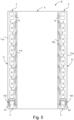
- Fig. 5 schematically illustrates a plan view of the tracked vehicle V in fig. 1 .
- the drive wheels 1 are operably connected to a drive axle 1a.
- the tracked vehicle V comprises a suspension system comprising a suspension device for the respective track assembly T1, T2.
- the respective track assembly T1, T2 of the vehicle V is thus arranged to be supported by the vehicle body 5 by means of said suspension device.
- the respective suspension device of the suspension system of the vehicle comprises according to this embodiment suspension arms 6 which may be denoted rocker arms or pendulum arms.
- the suspension arms 6 are in one end configured to be rotatably attached to the vehicle body 5 and in the opposite end configured to be rotatably attached to a respective road wheel 3.
- Said suspension arms 6 are configured such that forces acting on said plurality of road wheels 3 cause resilient oscillation of said suspension arms 6.
- the road wheels 3 of the respective track assembly of the vehicle V are thus arranged to be supported by the vehicle body 5 by means of said suspension arms 6 of the respective suspension device.
- Said track assemblies T1, T2 are thus suspendedly arranged to said vehicle body 5 via said road wheels 3 by means of the suspension system.
- the vehicle V described with reference to fig. 1 and 5 is a tracked vehicle with a left and right track assembly T1, T2 and a vehicle body to which the track assemblies are suspended attached.
- Each track assembly T1, T2 has a front end wheel in the form of a drive wheel 1 and a rear end wheel in the form of a tension wheel 2 and a plurality of road wheels 3 there between.
- Each track assembly T1, T2 comprises an endless track disposed around the wheels 1, 2, 3.
- a deflector arrangement 100 is coaxially and resiliently suspended with respect to the axis X1 of the tension wheel 2 of the respective track assembly T1, T2 and biasedly arranged so as to strive towards the inner surface of the endless track 4a.
- the plough arrangement 110 of the deflector arrangement 100 is arranged between said tension wheel 2 and adjacent road wheel 3 and configured to prevent such undesired material to be carried by said endless track around said tension wheel 2 during forward drive of the vehicle V.
- the deflector arrangement 100 could for such a vehicle alternatively be coaxially and resiliently suspended with respect to the axis of the road wheel 3 adjacent to the tension wheel 2 of the respective track assembly T1, T2 and biasedly arranged so as to strive towards the inner surface of the endless track 4a.
- the plough arrangement 110 of the deflector arrangement 100 would in this case also be arranged between said tension wheel 2 and adjacent road wheel 3 and configured to prevent such undesired material to be carried by said endless track around said tension wheel 2 during forward drive of the vehicle V.
- the deflector arrangement 100 could for such a vehicle also be coaxially and resiliently suspended with respect to the axis of the drive wheel 1 of the respective track assembly T1, T2 and biasedly arranged so as to strive towards the inner surface of the endless track 4a.
- the plough arrangement 110 of the deflector arrangement 100 would in this case be arranged between said drive wheel 1 and adjacent road wheel 3 and configured to prevent such undesired material to be carried by said endless track around said drive wheel 1 during backward drive of the vehicle V.
- the deflector arrangement 100 could for such a vehicle alternatively to arranging it on the drive wheel 1 be coaxially and resiliently suspended with respect to the axis of the road wheel 3 adjacent to the drive wheel 1 of the respective track assembly T1, T2 and biasedly arranged so as to strive towards the inner surface of the endless track 4a.
- the plough arrangement 110 of the deflector arrangement 100 would in this case also be arranged between said drive wheel 1 and adjacent road wheel 3 and configured to prevent such undesired material to be carried by said endless track around said drive wheel 1 during forward drive of the vehicle V.
- the tracked vehicle according to the present invention may be any suitable tracked vehicle with at least one track assembly comprising, where each track assembly comprises two end wheels in the form of a front wheel and a rear wheel, and further a plurality of road wheels there between, where at least one of the front wheel and rear wheel is a drive wheel and at least one of the front wheel and rear wheel is a tension wheel.
Landscapes
- Engineering & Computer Science (AREA)
- Chemical & Material Sciences (AREA)
- Combustion & Propulsion (AREA)
- Transportation (AREA)
- Mechanical Engineering (AREA)
- Platform Screen Doors And Railroad Systems (AREA)
- Tires In General (AREA)
- Devices For Conveying Motion By Means Of Endless Flexible Members (AREA)
Description
- The present invention relates to a deflector arrangement for a tracked vehicle. The present invention relates to a tracked vehicle.
- Tracked vehicles normally comprise a pair of track assemblies, where each track assembly of the pair of track assemblies comprises a front drive wheel, a rear tension wheel and a plurality of road wheels there between. The respective track assembly further comprises an endless track running over the drive wheel, the plurality of support wheels and the tensions wheel. Said drive wheel and said plurality of support wheels are rotatably secured to the vehicle body of the vehicle.
- Such tracked vehicles, e.g. combat vehicles, are intended to be driven in rough terrain. A problem during drive in rough terrain with such vehicle is that ingestion of undesired material such as gravel and stones into the respective track assembly and in between wheels and the endless track may occur which in turn cause damages to the tracked vehicle and in some cases may result in the endless track being torn apart.
-
US2637603A discloses a muck stripper for endless track treads for use in connection with drive sprockets, the stripper being arranged to prevent foreign material from being carried around the sprocket during operation of the endless track tread. -
US2008150355A1 discloses a deflector for reducing the ingestion of snow and/or other debris in one of the sprocket wheel and idler wheel area of a vehicle equipped with endless tracks. -
US20050046277A1 discloses a tracked vehicle comprising a cutter bar provided for trimming debris away from the wheel-track interface of the tracked vehicle. A pivot attachment is provided wherein a knife having a cutting edge is removably mounted to a bracket by way of fasteners which will shear when a pre-selected force is applied to them. The bracket is mounted to the vehicle structure so that the knife is disposed in close proximity to the drive wheel and endless track of the vehicle. -
SU 1751035A1 -
GB2357066A - There is however a need to present improvements in deflector arrangements for tracked vehicles.
- An object of the present invention is to provide a deflector arrangement for a tracked vehicle, which efficiently reduces ingestion of undesired material from the ground into said track assembly and facilitates removal of such undesired material from said track assembly.
- A further object of the present invention is to provide a tracked vehicle comprising such a deflector arrangement.
- These and other objects, which will become apparent from the following description, are achieved by a deflector arrangement for a tracked vehicle and a tracked vehicle as set out in the appended independent claim. Preferred embodiments of the deflector arrangement are defined in the appended dependent claims.
- Specifically an object of the invention is achieved by a deflector arrangement for a tracked vehicle. Said tracked vehicle comprises at least one track assembly comprising two end wheels in the form of a front wheel and a rear wheel, and further a plurality of road wheels there between. At least one of the front wheel and rear wheel is a drive wheel and at least one of the front wheel and rear wheel is a tension wheel. The track assembly further comprises an endless track, said endless track being disposed around said end wheels and plurality of road wheels. Said deflector arrangement is configured to reduce ingestion of undesired material from the ground into said track assembly and removal of such undesired material from said track assembly. Said deflector arrangement is associated with an end wheel and is resiliently suspended and biasedly arranged so as to strive towards the inner surface of the endless track. Said deflector arrangement comprises a support wheel arrangement configured to roll against the inner surface of said endless track during movement of said vehicle.
- By thus providing a deflector arrangement being associated with an end wheel and being resiliently suspended and biasedly arranged so as to strive towards the inner surface of the endless track, ingestion of undesired material from the ground such as gravel and stones into said track assembly is efficiently reduced. Further, removal of such undesired material from said track assembly is facilitated. This is due to the deflector arrangement being thus resiliently suspended and biased, resulting in the deflector arrangement smoothly adapting to the vehicle movements and at the same striving towards the inner surface of the endless track due to the biasing force, i.e. to a great extent is kept towards the inner surface of the endless track, and thereby essentially preventing such undesired material to be introduced into the track assembly in connection to the deflector arrangement and efficiently removing such undesired material that has been ingested into the track assembly when approaching the deflector arrangement so that no such material is allowed to travel around the end wheel between the end wheel and endless track. Thus, herby the risk of the endless track being torn apart due to undesired material from the ground being ingested into the track assembly may be efficiently avoided. Hereby an endless track of rubber material may advantageously be used. The risk of the deflector arrangement being damaged is, due to the deflector arrangement being resiliently suspended, reduced. The deflector arrangement may, due to the deflector arrangement being resiliently suspended, handle any movements of the endless track. The deflector arrangement may, due to the deflector arrangement being resiliently suspended, withstand high loads during vehicle operation. The deflector arrangement may, due to the deflector arrangement being resiliently suspended, withstand being tilted due to side forces in connection to the deflector arrangement.
- Said deflector arrangement may according to an embodiment be suspended with respect to an end wheel or a road wheel adjacent to that end wheel. Said deflector arrangement may be thus resiliently suspended and biasedly arranged so as to strive towards the inner surface of the endless track by means of a force.
- According to an embodiment of the deflector arrangement said deflector arrangement is coaxially suspended with respect to the axis of an end wheel or a road wheel adjacent to that end wheel. Hereby the deflector arrangement may be efficiently and easily resiliently suspended and biased.
- According to an embodiment of the deflector arrangement said deflector arrangement comprises a plough arrangement being arranged between said end wheel and adjacent road wheel and configured to prevent such undesired material to be carried by said endless track around said end wheel. Hereby prevention of such undesired material to be introduced into the track assembly in connection to the deflector arrangement is efficiently achieved and efficient removal of such undesired material is facilitated for the prevention of such undesired material to be carried by said endless track around said end wheel.
- As mentioned above, said deflector arrangement comprises a support wheel arrangement configured to roll against the inner surface of said endless track during movement of said vehicle. Hereby operation of the deflector arrangement is further improved in that the deflector arrangement due to the support wheel arrangement is allowed to roll freely relative to the endless track when the deflector arrangement strives towards the inner surface of the endless track. The risk of the deflector arrangement being damaged is, due to the thus provided support wheel arrangement, reduced.
- According to an embodiment of the deflector arrangement said support wheel arrangement is arranged in connection to the plough arrangement. Hereby operation of the deflector arrangement is further improved in that the deflector arrangement due to the support wheel arrangement arranged in connection to the plough arrangement is allowed to roll freely relative to the endless track when the deflector arrangement strives towards the inner surface of the endless track. The risk of the deflector arrangement being damaged is, due to the thus provided support wheel arrangement, reduced.
- According to an embodiment of the deflector arrangement said plough arrangement comprises a first plough member configured to be arranged on the outer side of the track assembly and a second plough member configured to be arranged on the inner side of the track assembly. Hereby prevention of such undesired material to be introduced into the track assembly in connection to the deflector arrangement is efficiently achieved and efficient removal such undesired material is facilitated for the prevention of such undesired material to be carried by said endless track around said end wheel.
- According to an embodiment of the deflector arrangement said deflector arrangement comprises first and second laterally disposed shield elements configured to protect the wheel to which it is coaxially suspended on the respective side of the wheel. Hereby efficient protection of the wheel to which the deflector arrangement is coaxially suspended is facilitated.
- According to an embodiment of the deflector arrangement said deflector arrangement is coaxially suspended to the hub of said axis, wherein each plough member is attached to said hub via said laterally disposed shield element.
- According to an embodiment of the deflector arrangement, the deflector arrangement is resiliently suspended and biasedly arranged by means of a spring arrangement.
- According to an embodiment of the deflector arrangement, the spring arrangement comprises bushings and/or a torsion spring arrangement arranged in connection to said hub of said axis. Hereby efficient resilience of the resiliently suspended deflector arrangement is obtained. Hereby efficient biasing of the biasedly arranged deflector arrangement is facilitated. The bushings may according to an embodiment be rubber bushings. Such bushings further facilitates for the deflector arrangement to withstand being tilted due to side forces in connection to the deflector arrangement.
- Specifically an object of the invention is achieved by a tracked vehicle comprising at least one deflector arrangement as set out herein.
- According to an embodiment of the tracked vehicle, said tracked vehicle comprises a left track assembly, a right track assembly and a vehicle body, wherein said track assemblies are suspendedly arranged to said vehicle body via said road wheels by means of a suspension system, each track assembly comprising at least one deflector arrangement.
- For a better understanding of the present invention reference is made to the following detailed description when read in conjunction with the accompanying drawings, wherein like reference characters refer to like parts throughout the several views, and in which:
-
Fig. 1 schematically illustrates a side view of a tracked vehicle according to an embodiment of the invention; -
Fig. 2 schematically illustrates a perspective view of a deflector arrangement according to an embodiment of the present disclosure, arranged in connection to a tension wheel of a tracked vehicle; -
Fig. 3a schematically illustrates a perspective view of the deflector arrangement infig. 2 ; -
Fig. 3b schematically illustrates another perspective view of the deflector arrangement infig. 2 ; -
Fig. 4 schematically illustrates a cross sectional view of a tension wheel in connection to which a deflector arrangement according to the present disclosure is configured to be arranged; and -
Fig. 5 schematically illustrates a plan view of the tracked vehicle infig. 1 ; - The tracked vehicle according to the present disclosure may be any suitable tracked vehicle. The tracked vehicle according to the present disclosure may comprise at least one track assembly comprising two end wheels in the form of a front wheel and a rear wheel, and further a plurality of road wheels there between. For the tracked vehicle according to the present disclosure, at least one of the front wheel and rear wheel may be a drive wheel and at least one of the front wheel and rear wheel may be a tension wheel. For the tracked vehicle according to the present disclosure, the track assembly further comprises an endless track, said endless track being disposed around said end wheels and plurality of road wheels.
-
Fig. 1 schematically illustrates a side view of a tracked vehicle V according to an embodiment of the present disclosure. The tracked vehicle V is driving on a ground G. The tracked vehicle V is a motor vehicle. The exemplified tracked vehicle V is constituted by a military tracked vehicle. - The tracked vehicle V comprises a track assembly pair comprising two track assemblies, a left track assembly T1 and a right track assembly, the left track assembly T1 being shown in
fig. 1 . The respective track assembly, here illustrated with the left track assembly T1, comprises twoend wheels front wheel 1 and arear wheel 2, and further a plurality ofroad wheels 3 there between. According to the embodiment infig. 1 , thefront wheel 1 is adrive wheel 1 and therear wheel 2 is atension wheel 2. The track assembly further comprises anendless track 4, saidendless track 4 being disposed around saidend wheels road wheels 3. Theendless track 4 is thus configured to run around thedrive wheel 1,tension wheel 2 and plurality ofroad wheels 3. Theendless track 4 is apropulsion track 4 running around saidwheels endless track 4 has an inner side with aninner surface 4a, which at least partly is in contact with thewheels wheels - The
drive wheel 1 is configured to be operated by any suitable drive means such as an internal combustion engine and or/or an electric motor. Thedrive wheel 1 is configured to be rotated by the drive means for rotating the endless track for driving the vehicle. The respective drive wheel of the vehicle V is configured to be rotated by the drive means. - Further the
vehicle 1 comprises avehicle body 5, which may include the chassis of the vehicle and bodywork. - The vehicle V comprises a suspension system comprising a suspension device for the respective track assembly. The respective track assembly of the vehicle V is thus arranged to be supported by the
vehicle body 5 by means of said suspension device. Theroad wheels 3 of the respective track assembly of the vehicle V is arranged to be supported by thevehicle body 5 by means of said suspension device. Hereby movability and comfort of the vehicle V is improved in that thevehicle body 5 is allowed to be raised and lowered relative to the track assembly. The suspension device is described in more detail with reference tofig. 5 . - The vehicle V comprises a
deflector arrangement 100 for the respective track assembly. Thedeflector arrangement 100 is configured to reduce ingestion of undesired material from the ground G into said track assembly T1 and removal of such undesired material from said track assembly T1. - Said
deflector arrangement 100 is associated with thetension wheel 2 and is resiliently suspended and biasedly arranged so as to strive towards theinner surface 4a of theendless track 4. - According to this embodiment the
deflector arrangement 100 is coaxially suspended with respect to the axis of thetension wheel 2. - The deflector arrangement comprises a
plough arrangement 110 being arranged between saidtension wheel 2 andadjacent road wheel 3 and configured to prevent such undesired material to be carried by said endless track around saidtension wheel 2. - Said
deflector arrangement 100 is suspended with respect to thetension wheel 2 and is resiliently suspended and biasedly arranged so as to strive towards theinner surface 4a of theendless track 4 by means of a force F.Said deflector arrangement 100 is coaxially suspended with respect to the axis of thetension wheel 2 and is resiliently suspended and biasedly arranged so as to strive towards theinner surface 4a of theendless track 4 by means of a force F. -
Fig. 2 schematically illustrates a perspective view of adeflector arrangement 100 according to an embodiment of the present disclosure, arranged in connection to atension wheel 2 of a tracked vehicle; andfig. 3a. and 3b schematically illustrate different perspective views of thedeflector arrangement 100 infig. 2 .Fig. 4 schematically illustrates a cross sectional view of thetension wheel 2 in connection to which thedeflector arrangement 100 according to the present disclosure is configured to be arranged. -
Fig. 2 thus shows a portion of the left track assembly T1. The track assembly T1 has an outer side T1a configured to face away from the vehicle and an inner side T1b configured to face the vehicle body, as shown infig. 5 .Fig. 2 schematically illustrates a perspective view of a portion of the track assembly T1 showing the outer side T1a of the track assembly, i.e. the side of the track assembly facing away from the vehicle body. Thus, the side of thetension wheel 2 facing away from the vehicle body is shown infig. 2 . - As described above with reference to
fig. 1 , thedeflector arrangement 100 is configured to reduce ingestion of undesired material from the ground into said track assembly and removal of such undesired material from said track assembly. - Said
deflector arrangement 100 is associated with thetension wheel 2 and is resiliently suspended and biasedly arranged so as to strive towards theinner surface 4a of theendless track 4. - According to this embodiment the
deflector arrangement 100 is coaxially suspended with respect to the axis X1 of thetension wheel 2. The axis X1 correspond to the axis about which thetension wheel 2 is configured to rotate. - The
tension wheel 2 comprises a hub H with the axis X1. According to this embodiment thedeflector arrangement 100 is coaxially suspended to the hub H of said axis X1. Thus, according to this embodiment thedeflector arrangement 100 is coaxially suspended to the hub H of thetension wheel 2. - The
deflector arrangement 100 is configured to be rotatably attached to the to thetension wheel 2. Thedeflector arrangement 100 is configured such that forces acting on theendless track 4 and transferred to thedeflector arrangement 100 cause resilient oscillation of said suspension of thedeflector arrangement 100. - The
tension wheel 2 comprises afirst wheel portion 2a and asecond wheel portion 2b. Thefirst wheel portion 2a is aleft wheel portion 2a, i.e.outer wheel portion 2a, and thesecond wheel portion 2b is aright wheel portion 2b, i.e. an inner wheel portion 2b. Saidwheel portions endless track 4 during rotation of saidendless track 4. Thegear portions endless track 4. Saidfirst wheel portion 2a is configured to be arranged on one side of the central protrusion and saidsecond wheel portion 2b is configured to be arranged on the opposite side of the central protrusion of theendless track 4. Thus, theleft wheel portion 2a is configured to run on the left side of the central protrusion and saidsecond wheel portion 2b is configured to run on the right side of the central protrusion of theendless track 4. - As described above with reference to
fig. 1 , thedeflector arrangement 100 comprises aplough arrangement 110 being arranged between saidtension wheel 2 and the adjacent road wheel, not shown infig. 2 , and configured to prevent such undesired material to be carried by saidendless track 110 around saidtension wheel 2. - According to this embodiment of the
deflector arrangement 100 saidplough arrangement 110 comprises afirst plough member 112 configured to be arranged in connection to the outer side T1a of the track assembly T1 and asecond plough member 114 configured to be arranged in connection to the inner side T1b of the track assembly T1. - The
plough arrangement 110 is adapted to the configuration of the inner side of theendless track 4 according to this embodiment. Thefirst plough member 112 is configured to run on the outer side of the central protrusion of theendless track 4 in front of theouter wheel portion 2a of thetension wheel 2. Thesecond plough member 114 is configured to run on the inner side of the central protrusion of theendless track 4 in front of theinner wheel portion 2b of thetension wheel 2. - The
first plough member 112 andsecond plough member 114 are according to this embodiment of theplough arrangement 110 connected via acentral plough portion 116 running over the inner central protrusion of theendless track 4. Theplough arrangement 110 according to this embodiment thus comprises acentral plough portion 116 arranged between thefirst plough member 112 andsecond plough member 114. - As shown in
fig. 3a and fig. 3b saiddeflector arrangement 100, according to this embodiment, comprises asupport wheel arrangement 120 configured to roll against theinner surface 4a of saidendless track 4 during movement of said vehicle. - According to this embodiment said
support wheel arrangement 120 is arranged in connection to theplough arrangement 110. Saidsupport wheel arrangement 120 is arranged in connection to theplough arrangement 110 so that thewheel members support wheel arrangement 120 are configured to roll against theinner surface 4a of saidendless track 4 during movement of said vehicle. - According to this embodiment the
support wheel arrangement 120 comprises afirst wheel member 122 arranged in connection to thefirst plough member 112. A portion of thefirst wheel member 122 is configured to protrude from the underside, i.e. the side configured to face theinner side 4a of thetrack 4, of thefirst plough member 112. According to an embodiment thefirst wheel member 122 is journalled in bearings in connection to thefirst plough member 112. - According to this embodiment the
support wheel arrangement 120 comprises asecond wheel member 124 arranged in connection to thesecond plough member 114. A portion of thesecond wheel member 124 is configured to protrude from the underside, i.e. the side configured to face theinner side 4a of thetrack 4, of thesecond plough member 114. According to an embodiment thesecond wheel member 124 is journalled in bearings in connection to thesecond plough member 114. - According to this embodiment said
deflector arrangement 100 comprises afirst shield element 130 configured to protect thetension wheel 2 on the outer side of thetension wheel 2. Thefirst shield element 130 is coaxially suspended to the hub H of thetension wheel 2. Thefirst shield element 130 is coaxially suspended to the hub H of thetension wheel 2 in connection the outer side of thetension wheel 2. Thefirst shield element 130 is laterally disposed on the outer side of thetension wheel 2. - The
first shield element 130 has an extension in a plane essentially orthogonal to the transversal extension of said track assembly. Thefirst shield element 130 has a flat configuration. Thefirst shield element 130 has alower portion 130a configured to face theinner side 4a of the endless track. Thelower portion 130a of the first shield element is configured to run along theinner side 4a of theendless track 4. - The
first shield element 130 is arranged to run forwardly along the outer side of thetension wheel 2 to a certain position passed thetension wheel 2, afront portion 130b of thefirst shield element 130 constituting the front end of thefirst shield element 130. Thefront portion 130b of thefirst shield element 130 has a rearward inclination from thelower portion 130a and upwardly. - The
first shield element 130 is attached to thefirst plough member 112. Thefirst plough member 112 is connected to thefirst shield element 130 at thefront portion 130b of thefirst shield element 130. Thefirst plough member 112 is attached to the hub H via thefirst shield element 130. - The
first shield element 130 may be a separate part attached to theplough arrangement 110, i.e. thefirst plough member 112, or an integrated portion where thefirst shield element 130 and thefirst plough member 112 are portions of thedeflector arrangement 100. - According to this embodiment said
deflector arrangement 100 comprises asecond shield element 140 configured to protect thetension wheel 2 on the inner side of thetension wheel 2. Thesecond shield element 140 is coaxially suspended to the hub H of thetension wheel 2 in connection the inner side of thetension wheel 2. Thesecond shield element 140 is laterally disposed on the inner side of thetension wheel 2. - The
second shield element 140 has an extension in a plane essentially orthogonal to the transversal extension of said track assembly. Thesecond shield element 140 has a flat configuration. Thesecond shield element 140 has alower portion 140a configured to face theinner side 4a of the endless track. Thelower portion 140a of the second shield element is configured to run along theinner side 4a of theendless track 4. - The
second shield element 140 is attached to thesecond plough member 114. Thesecond plough member 114 is connected to thesecond shield element 140 at afront portion 140b of thesecond shield element 140. Thesecond plough member 114 is attached to the hub H via thesecond shield element 140. - The
second shield element 140 may be a separate part attached to theplough arrangement 110, i.e. thesecond plough member 114, or an integrated portion where thesecond shield element 140 and thesecond plough member 114 are portions of thedeflector arrangement 100. - The
second shield element 140 is arranged to run forwardly along the outer side of thetension wheel 2 to a certain position passed thetension wheel 2, afront portion 140b of thesecond shield element 140 constituting the front end of thesecond shield element 140. Thefront portion 140b of thesecond shield element 140 has a rearward inclination from thelower portion 140a and upwardly. - The
plough arrangement 110 of the deflector arrangement is arranged in connection to thefront portions second shield elements - Thus, according to the embodiment of said
deflector arrangement 100 illustrated infig. 2 and3a-b , thedeflector arrangement 100 is coaxially suspended to the hub H of said axis X1, wherein eachplough member shield elements - As shown e.g. in
fig. 3a and 3b saiddeflector arrangement 100 comprises afirst suspension member 150 arranged in connection to thefirst shield element 130. Thefirst suspension member 150 may be a portion of thefirst shield element 130 or attached to thefirst shield element 130. Thefirst suspension member 150 is arranged in connection to an upper portion 130c of thefirst shield element 130. Thefirst suspension member 150 has an opening O1, seefig. 3a-b , for receiving the hub H of thetension wheel 2 as shown infig. 2 andfig. 4 described in more detail below. The opening O1 is thus coaxial relative to the axis X1. - As shown in
fig. 3a-b andfig. 4 thefirst suspension member 150 comprises a first bushing B1 arranged in connection to the opening O1 of thefirst suspension member 150. The first bushing B1 is ring shaped. - The
first suspension member 150 is configured to be coaxially suspended to the hub H of thetension wheel 2. The first bushing B1 is configured to provide a resilient suspension for thedeflector arrangement 100 when thefirst suspension member 150 is coaxially suspended to the hub H. The first bushing B1 is configured to facilitate a biased arrangement for thedeflector arrangement 100 when thefirst suspension member 150 is coaxially suspended to the hub H. - As shown e.g. in
fig. 3a and 3b saiddeflector arrangement 100 comprises asecond suspension member 160 arranged in connection to thesecond shield element 140. Thesecond suspension member 160 may be a portion of thesecond shield element 140 or attached to thesecond shield element 140. Thesecond suspension member 160 is arranged in connection tocentral portion 140c of thesecond shield element 140. Thesecond suspension member 160 an opening for receiving a screw joint member J shown infig. 3a-b andfig. 4 . The screw joint member J is configured to attach thedeflector arrangement 100 to thetension wheel 2 in connection to thesecond shield element 140. - As shown in
fig. 3a-b andfig. 4 thesecond suspension member 160 comprises a second bushing B2 arranged in connection to the opening O1 of thesecond suspension member 160. The second bushing B2 is ring shaped. - The
second suspension member 160 is configured to be coaxially suspended to the hub H of thetension wheel 2. The second bushing B2 is configured to provide a resilient suspension for thedeflector arrangement 100 when thesecond suspension member 160 is coaxially suspended to the hub H. The second bushing B2 is configured to facilitate a biased arrangement for thedeflector arrangement 100 when thesecond suspension member 160 is coaxially suspended to the hub H. - The bushings B1, B2 are thus comprised in or comprise or constitute a spring arrangement for providing the resilient suspension of the deflector arrangement. The bushings B1, B2 are thus comprised in or comprise or constitute a biasing arrangement for providing the biasing arrangement of the deflector arrangement so that it strives towards the inner surface of the endless track. The biasing arrangement may be comprised in the spring arrangement. Thus, according to an embodiment of the present invention the
deflector arrangement 100 comprises a spring arrangement B1, B2. - The resilient suspension of the deflector arrangement according to the present invention and the biased arrangement so that the deflector arrangement strives towards the inner surface of the endless track may be obtained by any suitable spring arrangement. According to an embodiment the spring arrangement comprises a torsion spring arrangement. Such a torsion spring arrangement is according to an embodiment configured to be arranged in connection to the hub of the tension wheel. Such a torsion spring arrangement is configured to provide the resilient suspension of the deflector arrangement and the biased arrangement so that the deflector arrangement strives towards the inner surface of the endless track.
-
Fig. 5 schematically illustrates a plan view of the tracked vehicle V infig. 1 . - Here the right track assembly T1 and the left track assembly T2 of the tracked vehicle V are shown.
- The
drive wheels 1 are operably connected to adrive axle 1a. - As mentioned above the tracked vehicle V comprises a suspension system comprising a suspension device for the respective track assembly T1, T2. The respective track assembly T1, T2 of the vehicle V is thus arranged to be supported by the
vehicle body 5 by means of said suspension device. - The respective suspension device of the suspension system of the vehicle comprises according to this
embodiment suspension arms 6 which may be denoted rocker arms or pendulum arms. Thesuspension arms 6 are in one end configured to be rotatably attached to thevehicle body 5 and in the opposite end configured to be rotatably attached to arespective road wheel 3. Saidsuspension arms 6 are configured such that forces acting on said plurality ofroad wheels 3 cause resilient oscillation of saidsuspension arms 6. - The
road wheels 3 of the respective track assembly of the vehicle V are thus arranged to be supported by thevehicle body 5 by means of saidsuspension arms 6 of the respective suspension device. - Said track assemblies T1, T2 are thus suspendedly arranged to said
vehicle body 5 via saidroad wheels 3 by means of the suspension system. - The vehicle V described with reference to
fig. 1 and5 is a tracked vehicle with a left and right track assembly T1, T2 and a vehicle body to which the track assemblies are suspended attached. Each track assembly T1, T2 has a front end wheel in the form of adrive wheel 1 and a rear end wheel in the form of atension wheel 2 and a plurality ofroad wheels 3 there between. Each track assembly T1, T2 comprises an endless track disposed around thewheels - A
deflector arrangement 100 is coaxially and resiliently suspended with respect to the axis X1 of thetension wheel 2 of the respective track assembly T1, T2 and biasedly arranged so as to strive towards the inner surface of theendless track 4a. Theplough arrangement 110 of thedeflector arrangement 100 is arranged between saidtension wheel 2 andadjacent road wheel 3 and configured to prevent such undesired material to be carried by said endless track around saidtension wheel 2 during forward drive of the vehicle V. - The
deflector arrangement 100 could for such a vehicle alternatively be coaxially and resiliently suspended with respect to the axis of theroad wheel 3 adjacent to thetension wheel 2 of the respective track assembly T1, T2 and biasedly arranged so as to strive towards the inner surface of theendless track 4a. Theplough arrangement 110 of thedeflector arrangement 100 would in this case also be arranged between saidtension wheel 2 andadjacent road wheel 3 and configured to prevent such undesired material to be carried by said endless track around saidtension wheel 2 during forward drive of the vehicle V. - The
deflector arrangement 100 could for such a vehicle also be coaxially and resiliently suspended with respect to the axis of thedrive wheel 1 of the respective track assembly T1, T2 and biasedly arranged so as to strive towards the inner surface of theendless track 4a. Theplough arrangement 110 of thedeflector arrangement 100 would in this case be arranged between saiddrive wheel 1 andadjacent road wheel 3 and configured to prevent such undesired material to be carried by said endless track around saiddrive wheel 1 during backward drive of the vehicle V. - The
deflector arrangement 100 could for such a vehicle alternatively to arranging it on thedrive wheel 1 be coaxially and resiliently suspended with respect to the axis of theroad wheel 3 adjacent to thedrive wheel 1 of the respective track assembly T1, T2 and biasedly arranged so as to strive towards the inner surface of theendless track 4a. Theplough arrangement 110 of thedeflector arrangement 100 would in this case also be arranged between saiddrive wheel 1 andadjacent road wheel 3 and configured to prevent such undesired material to be carried by said endless track around saiddrive wheel 1 during forward drive of the vehicle V. - The tracked vehicle according to the present invention may be any suitable tracked vehicle with at least one track assembly comprising, where each track assembly comprises two end wheels in the form of a front wheel and a rear wheel, and further a plurality of road wheels there between, where at least one of the front wheel and rear wheel is a drive wheel and at least one of the front wheel and rear wheel is a tension wheel.
Claims (11)
- A deflector arrangement (100) for a tracked vehicle (V), said tracked vehicle (V) comprising at least one track assembly (T1, T2) comprising two end wheels (1, 2) in the form of a front wheel (1) and a rear wheel (2), and further a plurality of road wheels (3) there between, at least one of the front wheel (1) and rear wheel (2) being a drive wheel (1) and at least one of the front wheel (1) and rear wheel (2) being a tension wheel (2), the track assembly (T1, T2) further comprising an endless track (4), said endless track (4) being disposed around said end wheels (1, 2) and plurality of road wheels (3), said deflector arrangement (100) being configured to reduce ingestion of undesired material from the ground (G) into said track assembly (T1, T2) and removal of such undesired material from said track assembly (T1, T2), said deflector arrangement (100) being associated with an end wheel (1, 2) and being resiliently suspended and biasedly arranged so as to strive towards the inner surface (4a) of the endless track (4), characterized in that said deflector arrangement (100) comprises a support wheel arrangement (120) configured to roll against the inner surface (4a) of said endless track (4) during movement of said vehicle (V).
- A deflector arrangement according to claim 1, wherein said deflector arrangement (100) is coaxially suspended with respect to the axis (X1, X2) of an end wheel (1, 2) or a road wheel (3) adjacent to that end wheel.
- A deflector arrangement according to claim 2, wherein said deflector arrangement (100) comprises a plough arrangement (110) being arranged between said end wheel (1, 2) and adjacent road wheel (3) and configured to prevent such undesired material to be carried by said endless track (4) around said end wheel (1, 2).
- A deflector arrangement according to claim 3, wherein said support wheel arrangement (120) is arranged in connection to the plough arrangement (110).
- A deflector arrangement according to claim 3 or 4, wherein said plough arrangement (110) comprises a first plough member (112) configured to be arranged on the outer side (T1a, T2a) of the track assembly (T1, T2) and a second plough member (114) configured to be arranged on the inner side (T1b, T2b) of the track assembly (T1, T2).
- A deflector arrangement according to any of claims 1-5, wherein said deflector arrangement (100) comprises first and second laterally disposed shield elements (130, 140) configured to protect the wheel to which it is coaxially suspended on the respective side of the wheel.
- A deflector arrangement according to claim 6, wherein said deflector arrangement (100) is coaxially suspended to the hub (H) of said axis (X1, X2), wherein each plough member (112, 114) is attached to said hub (H) via said laterally disposed shield element (130, 140).
- A deflector arrangement according to claim 7, wherein the deflector arrangement (100) is resiliently suspended and biasedly arranged by means of a spring arrangement (B1, B2).
- A deflector arrangement according to claim 8, wherein the spring arrangement (B1, B2) comprises bushings (150, 160) and/or a torsion spring arrangement arranged in connection to said hub (H) of said axis (X1, X2).
- A tracked vehicle (V) comprising at least one deflector arrangement (100) according to any of claims 1-9.
- A tracked vehicle (V) according to claim 10, wherein said tracked vehicle comprises a left track assembly (T1), a right track assembly (T2) and a vehicle body (5), wherein said track assemblies (T1, T2) are suspendedly arranged to said vehicle body via said road wheels (3) by means of a suspension system, each track assembly (T1, T2) comprising at least one deflector arrangement (100).
Priority Applications (1)
| Application Number | Priority Date | Filing Date | Title |
|---|---|---|---|
| RS20240786A RS65732B1 (en) | 2018-07-09 | 2019-07-02 | Deflector arrangement for a tracked vehicle |
Applications Claiming Priority (2)
| Application Number | Priority Date | Filing Date | Title |
|---|---|---|---|
| SE1850862A SE542471C2 (en) | 2018-07-09 | 2018-07-09 | Deflector arrangement for a tracked vehicle |
| PCT/SE2019/050658 WO2020013751A1 (en) | 2018-07-09 | 2019-07-02 | Deflector arrangement for a tracked vehicle |
Publications (4)
| Publication Number | Publication Date |
|---|---|
| EP3820764A1 EP3820764A1 (en) | 2021-05-19 |
| EP3820764A4 EP3820764A4 (en) | 2022-03-02 |
| EP3820764B1 true EP3820764B1 (en) | 2024-04-24 |
| EP3820764C0 EP3820764C0 (en) | 2024-04-24 |
Family
ID=69142761
Family Applications (1)
| Application Number | Title | Priority Date | Filing Date |
|---|---|---|---|
| EP19833632.3A Active EP3820764B1 (en) | 2018-07-09 | 2019-07-02 | Deflector arrangement for a tracked vehicle |
Country Status (8)
| Country | Link |
|---|---|
| US (1) | US11834114B2 (en) |
| EP (1) | EP3820764B1 (en) |
| ES (1) | ES2983812T3 (en) |
| HU (1) | HUE067533T2 (en) |
| PL (1) | PL3820764T3 (en) |
| RS (1) | RS65732B1 (en) |
| SE (1) | SE542471C2 (en) |
| WO (1) | WO2020013751A1 (en) |
Families Citing this family (3)
| Publication number | Priority date | Publication date | Assignee | Title |
|---|---|---|---|---|
| US11827295B2 (en) * | 2020-12-18 | 2023-11-28 | Howe & Howe Inc. | Utilizing a suspension protector to deflect debris away from a set of suspension components of a tracked vehicle |
| SE544933C2 (en) * | 2021-04-23 | 2023-01-10 | Bae Systems Haegglunds Ab | Method and device for determining potential damage of an endless track of a tracked vehicle |
| SE545413C2 (en) * | 2021-12-20 | 2023-09-05 | Bae Systems Haegglunds Ab | Deflector arrangement for a tracked vehicle |
Family Cites Families (17)
| Publication number | Priority date | Publication date | Assignee | Title |
|---|---|---|---|---|
| US2571285A (en) * | 1949-02-04 | 1951-10-16 | Deere & Co | Press wheel scraper |
| US2637603A (en) | 1951-12-07 | 1953-05-05 | Goodman Mfg Co | Muck stripper for endless track treads |
| US2982584A (en) * | 1958-02-26 | 1961-05-02 | Uemura Koichi | Automatic cleaning device for tractor shoes |
| SU1751035A1 (en) | 1990-08-16 | 1992-07-30 | Белорусский Политехнический Институт | Track-cleaning device of vehicle |
| US5226703A (en) * | 1992-04-20 | 1993-07-13 | Link-Belt Construction Co. | Idler roller mounting/scraper for track vehicle |
| US5697683A (en) | 1996-12-13 | 1997-12-16 | Caterpillar Inc. | Biased scraping apparatus for an idler |
| US6267458B1 (en) | 1999-12-08 | 2001-07-31 | Caterpillar Inc. | Apparatus for protecting a track assembly of a tractor |
| US6527347B2 (en) * | 2001-06-21 | 2003-03-04 | Caterpillar Inc | Scraping apparatus for a track idler |
| US6921140B2 (en) | 2003-08-28 | 2005-07-26 | Deere & Company | Cutter bar pivot attachment |
| US7380628B2 (en) * | 2003-11-24 | 2008-06-03 | Bombardier Recreational Products Inc. | Snowmobile track scraper |
| CA2504051C (en) * | 2004-06-09 | 2012-10-02 | Soucy International Inc. | A device to reduce the accumulation of snow and other debris in the wheels of tracked vehicles |
| US7832814B2 (en) | 2005-06-02 | 2010-11-16 | Soucy International Inc. | Snow and debris deflector for a track system |
| US7980639B2 (en) * | 2008-02-11 | 2011-07-19 | Caterpillar Inc. | Debris guard for track roller frame and machine using same |
| US8845039B2 (en) * | 2010-12-14 | 2014-09-30 | Caterpillar Inc. | Undercarriage system for track-type machine and debris shunting awning assembly |
| JP2015067208A (en) * | 2013-09-30 | 2015-04-13 | ヤンマー株式会社 | Work vehicle |
| US9872423B2 (en) | 2015-06-30 | 2018-01-23 | Cnh Industrial America Llc | Adjustable press wheel scraper |
| DE102016102715A1 (en) * | 2016-02-16 | 2017-08-17 | Krauss-Maffei Wegmann Gmbh & Co. Kg | Chain drive for military vehicles |
-
2018
- 2018-07-09 SE SE1850862A patent/SE542471C2/en unknown
-
2019
- 2019-07-02 EP EP19833632.3A patent/EP3820764B1/en active Active
- 2019-07-02 WO PCT/SE2019/050658 patent/WO2020013751A1/en not_active Ceased
- 2019-07-02 ES ES19833632T patent/ES2983812T3/en active Active
- 2019-07-02 HU HUE19833632A patent/HUE067533T2/en unknown
- 2019-07-02 US US17/258,687 patent/US11834114B2/en active Active
- 2019-07-02 PL PL19833632.3T patent/PL3820764T3/en unknown
- 2019-07-02 RS RS20240786A patent/RS65732B1/en unknown
Also Published As
| Publication number | Publication date |
|---|---|
| PL3820764T3 (en) | 2024-09-09 |
| WO2020013751A1 (en) | 2020-01-16 |
| EP3820764A4 (en) | 2022-03-02 |
| US20210269107A1 (en) | 2021-09-02 |
| ES2983812T3 (en) | 2024-10-24 |
| US11834114B2 (en) | 2023-12-05 |
| EP3820764C0 (en) | 2024-04-24 |
| SE1850862A1 (en) | 2020-01-10 |
| EP3820764A1 (en) | 2021-05-19 |
| HUE067533T2 (en) | 2024-10-28 |
| RS65732B1 (en) | 2024-08-30 |
| SE542471C2 (en) | 2020-05-19 |
Similar Documents
| Publication | Publication Date | Title |
|---|---|---|
| CA2701662C (en) | Track assembly for an all-terrain vehicle (atv) or other tracked vehicle | |
| US5373909A (en) | Tracked vehicles and power drive apparatus for motivating tracked vehicles | |
| EP2607212B1 (en) | Fender mounting assembly for utility vehicles | |
| EP2736794B1 (en) | Track-module apparatus and open drive wheel therefor | |
| US11958549B2 (en) | Standard component of a vehicle with a connector dedicated to connecting a track system to the vehicle | |
| US6802517B1 (en) | Fender skirt and methods for using same | |
| US11834114B2 (en) | Deflector arrangement for a tracked vehicle | |
| US20170305483A1 (en) | Adjustable and removable track assembly for a tractor | |
| US7527298B2 (en) | Dust fender for riding type work vehicle | |
| US20190126980A1 (en) | Steerable knuckle | |
| US20150183464A1 (en) | Torsional Suspensioned, Steerable, Oscillating and Propelling Axle Assembly | |
| US20250026419A1 (en) | Deflector arrangement for a tracked vehicle | |
| JP7057735B2 (en) | Crawler type traveling device and work vehicle | |
| US7343725B2 (en) | Cutting attachment for vehicle | |
| US3489234A (en) | Snowmobile suspension | |
| BR112024009209B1 (en) | DEFLECTION ARRANGEMENT FOR A TRACKED VEHICLE AND TRACKED VEHICLE | |
| JP2001086801A (en) | Running gear for walking type tending machine | |
| JP7125053B2 (en) | lawn mower | |
| JPH0412873Y2 (en) | ||
| JP4121172B2 (en) | Crawler belt | |
| JP3856633B2 (en) | Crawler traveling vehicle mounting device for crawler traveling vehicle |
Legal Events
| Date | Code | Title | Description |
|---|---|---|---|
| STAA | Information on the status of an ep patent application or granted ep patent |
Free format text: STATUS: THE INTERNATIONAL PUBLICATION HAS BEEN MADE |
|
| PUAI | Public reference made under article 153(3) epc to a published international application that has entered the european phase |
Free format text: ORIGINAL CODE: 0009012 |
|
| STAA | Information on the status of an ep patent application or granted ep patent |
Free format text: STATUS: REQUEST FOR EXAMINATION WAS MADE |
|
| 17P | Request for examination filed |
Effective date: 20201204 |
|
| AK | Designated contracting states |
Kind code of ref document: A1 Designated state(s): AL AT BE BG CH CY CZ DE DK EE ES FI FR GB GR HR HU IE IS IT LI LT LU LV MC MK MT NL NO PL PT RO RS SE SI SK SM TR |
|
| DAV | Request for validation of the european patent (deleted) | ||
| DAX | Request for extension of the european patent (deleted) | ||
| REG | Reference to a national code |
Ref country code: DE Ipc: B62D0055084000 Ref country code: DE Ref legal event code: R079 Ref document number: 602019051044 Country of ref document: DE Free format text: PREVIOUS MAIN CLASS: B62D0055088000 Ipc: B62D0055084000 |
|
| A4 | Supplementary search report drawn up and despatched |
Effective date: 20220202 |
|
| RIC1 | Information provided on ipc code assigned before grant |
Ipc: B62D 55/088 20060101ALI20220127BHEP Ipc: B62D 55/108 20060101ALI20220127BHEP Ipc: B62D 55/084 20060101AFI20220127BHEP |
|
| GRAP | Despatch of communication of intention to grant a patent |
Free format text: ORIGINAL CODE: EPIDOSNIGR1 |
|
| STAA | Information on the status of an ep patent application or granted ep patent |
Free format text: STATUS: GRANT OF PATENT IS INTENDED |
|
| INTG | Intention to grant announced |
Effective date: 20231127 |
|
| GRAS | Grant fee paid |
Free format text: ORIGINAL CODE: EPIDOSNIGR3 |
|
| GRAA | (expected) grant |
Free format text: ORIGINAL CODE: 0009210 |
|
| STAA | Information on the status of an ep patent application or granted ep patent |
Free format text: STATUS: THE PATENT HAS BEEN GRANTED |
|
| AK | Designated contracting states |
Kind code of ref document: B1 Designated state(s): AL AT BE BG CH CY CZ DE DK EE ES FI FR GB GR HR HU IE IS IT LI LT LU LV MC MK MT NL NO PL PT RO RS SE SI SK SM TR |
|
| REG | Reference to a national code |
Ref country code: GB Ref legal event code: FG4D |
|
| REG | Reference to a national code |
Ref country code: CH Ref legal event code: EP |
|
| REG | Reference to a national code |
Ref country code: DE Ref legal event code: R096 Ref document number: 602019051044 Country of ref document: DE |
|
| REG | Reference to a national code |
Ref country code: IE Ref legal event code: FG4D |
|
| U01 | Request for unitary effect filed |
Effective date: 20240521 |
|
| U07 | Unitary effect registered |
Designated state(s): AT BE BG DE DK EE FI FR IT LT LU LV MT NL PT SE SI Effective date: 20240703 |
|
| U20 | Renewal fee for the european patent with unitary effect paid |
Year of fee payment: 6 Effective date: 20240701 |
|
| REG | Reference to a national code |
Ref country code: SK Ref legal event code: T3 Ref document number: E 44575 Country of ref document: SK |
|
| PG25 | Lapsed in a contracting state [announced via postgrant information from national office to epo] |
Ref country code: IS Free format text: LAPSE BECAUSE OF FAILURE TO SUBMIT A TRANSLATION OF THE DESCRIPTION OR TO PAY THE FEE WITHIN THE PRESCRIBED TIME-LIMIT Effective date: 20240824 |
|
| PG25 | Lapsed in a contracting state [announced via postgrant information from national office to epo] |
Ref country code: HR Free format text: LAPSE BECAUSE OF FAILURE TO SUBMIT A TRANSLATION OF THE DESCRIPTION OR TO PAY THE FEE WITHIN THE PRESCRIBED TIME-LIMIT Effective date: 20240424 |
|
| PG25 | Lapsed in a contracting state [announced via postgrant information from national office to epo] |
Ref country code: GR Free format text: LAPSE BECAUSE OF FAILURE TO SUBMIT A TRANSLATION OF THE DESCRIPTION OR TO PAY THE FEE WITHIN THE PRESCRIBED TIME-LIMIT Effective date: 20240725 |
|
| REG | Reference to a national code |
Ref country code: ES Ref legal event code: FG2A Ref document number: 2983812 Country of ref document: ES Kind code of ref document: T3 Effective date: 20241024 |
|
| REG | Reference to a national code |
Ref country code: HU Ref legal event code: AG4A Ref document number: E067533 Country of ref document: HU |
|
| PG25 | Lapsed in a contracting state [announced via postgrant information from national office to epo] |
Ref country code: IS Free format text: LAPSE BECAUSE OF FAILURE TO SUBMIT A TRANSLATION OF THE DESCRIPTION OR TO PAY THE FEE WITHIN THE PRESCRIBED TIME-LIMIT Effective date: 20240824 Ref country code: HR Free format text: LAPSE BECAUSE OF FAILURE TO SUBMIT A TRANSLATION OF THE DESCRIPTION OR TO PAY THE FEE WITHIN THE PRESCRIBED TIME-LIMIT Effective date: 20240424 Ref country code: GR Free format text: LAPSE BECAUSE OF FAILURE TO SUBMIT A TRANSLATION OF THE DESCRIPTION OR TO PAY THE FEE WITHIN THE PRESCRIBED TIME-LIMIT Effective date: 20240725 |
|
| PG25 | Lapsed in a contracting state [announced via postgrant information from national office to epo] |
Ref country code: RO Free format text: LAPSE BECAUSE OF FAILURE TO SUBMIT A TRANSLATION OF THE DESCRIPTION OR TO PAY THE FEE WITHIN THE PRESCRIBED TIME-LIMIT Effective date: 20240424 |
|
| REG | Reference to a national code |
Ref country code: DE Ref legal event code: R097 Ref document number: 602019051044 Country of ref document: DE |
|
| PG25 | Lapsed in a contracting state [announced via postgrant information from national office to epo] |
Ref country code: SM Free format text: LAPSE BECAUSE OF FAILURE TO SUBMIT A TRANSLATION OF THE DESCRIPTION OR TO PAY THE FEE WITHIN THE PRESCRIBED TIME-LIMIT Effective date: 20240424 |
|
| PG25 | Lapsed in a contracting state [announced via postgrant information from national office to epo] |
Ref country code: SM Free format text: LAPSE BECAUSE OF FAILURE TO SUBMIT A TRANSLATION OF THE DESCRIPTION OR TO PAY THE FEE WITHIN THE PRESCRIBED TIME-LIMIT Effective date: 20240424 Ref country code: RO Free format text: LAPSE BECAUSE OF FAILURE TO SUBMIT A TRANSLATION OF THE DESCRIPTION OR TO PAY THE FEE WITHIN THE PRESCRIBED TIME-LIMIT Effective date: 20240424 |
|
| PG25 | Lapsed in a contracting state [announced via postgrant information from national office to epo] |
Ref country code: MC Free format text: LAPSE BECAUSE OF FAILURE TO SUBMIT A TRANSLATION OF THE DESCRIPTION OR TO PAY THE FEE WITHIN THE PRESCRIBED TIME-LIMIT Effective date: 20240424 |
|
| PLBE | No opposition filed within time limit |
Free format text: ORIGINAL CODE: 0009261 |
|
| REG | Reference to a national code |
Ref country code: CH Ref legal event code: PL |
|
| STAA | Information on the status of an ep patent application or granted ep patent |
Free format text: STATUS: NO OPPOSITION FILED WITHIN TIME LIMIT |
|
| 26N | No opposition filed |
Effective date: 20250127 |
|
| PG25 | Lapsed in a contracting state [announced via postgrant information from national office to epo] |
Ref country code: CH Free format text: LAPSE BECAUSE OF NON-PAYMENT OF DUE FEES Effective date: 20240731 |
|
| U20 | Renewal fee for the european patent with unitary effect paid |
Year of fee payment: 7 Effective date: 20250523 |
|
| PGFP | Annual fee paid to national office [announced via postgrant information from national office to epo] |
Ref country code: PL Payment date: 20250609 Year of fee payment: 7 |
|
| PGFP | Annual fee paid to national office [announced via postgrant information from national office to epo] |
Ref country code: GB Payment date: 20250516 Year of fee payment: 7 |
|
| PGFP | Annual fee paid to national office [announced via postgrant information from national office to epo] |
Ref country code: RS Payment date: 20250508 Year of fee payment: 7 Ref country code: NO Payment date: 20250624 Year of fee payment: 7 |
|
| PGFP | Annual fee paid to national office [announced via postgrant information from national office to epo] |
Ref country code: SK Payment date: 20250523 Year of fee payment: 7 Ref country code: TR Payment date: 20250508 Year of fee payment: 7 |
|
| PGFP | Annual fee paid to national office [announced via postgrant information from national office to epo] |
Ref country code: CZ Payment date: 20250430 Year of fee payment: 7 |
|
| PG25 | Lapsed in a contracting state [announced via postgrant information from national office to epo] |
Ref country code: IE Free format text: LAPSE BECAUSE OF NON-PAYMENT OF DUE FEES Effective date: 20240702 |
|
| PGFP | Annual fee paid to national office [announced via postgrant information from national office to epo] |
Ref country code: HU Payment date: 20250523 Year of fee payment: 7 |
|
| PGFP | Annual fee paid to national office [announced via postgrant information from national office to epo] |
Ref country code: ES Payment date: 20250926 Year of fee payment: 7 |
|
| PG25 | Lapsed in a contracting state [announced via postgrant information from national office to epo] |
Ref country code: CY Free format text: LAPSE BECAUSE OF FAILURE TO SUBMIT A TRANSLATION OF THE DESCRIPTION OR TO PAY THE FEE WITHIN THE PRESCRIBED TIME-LIMIT; INVALID AB INITIO Effective date: 20190702 |