EP3820555B1 - A securement device for pipes, cables or catheters - Google Patents
A securement device for pipes, cables or catheters Download PDFInfo
- Publication number
- EP3820555B1 EP3820555B1 EP19744628.9A EP19744628A EP3820555B1 EP 3820555 B1 EP3820555 B1 EP 3820555B1 EP 19744628 A EP19744628 A EP 19744628A EP 3820555 B1 EP3820555 B1 EP 3820555B1
- Authority
- EP
- European Patent Office
- Prior art keywords
- securement device
- article
- base
- catheter
- slot
- Prior art date
- Legal status (The legal status is an assumption and is not a legal conclusion. Google has not performed a legal analysis and makes no representation as to the accuracy of the status listed.)
- Active
Links
Images




Classifications
-
- A—HUMAN NECESSITIES
- A61—MEDICAL OR VETERINARY SCIENCE; HYGIENE
- A61M—DEVICES FOR INTRODUCING MEDIA INTO, OR ONTO, THE BODY; DEVICES FOR TRANSDUCING BODY MEDIA OR FOR TAKING MEDIA FROM THE BODY; DEVICES FOR PRODUCING OR ENDING SLEEP OR STUPOR
- A61M25/00—Catheters; Hollow probes
- A61M25/01—Introducing, guiding, advancing, emplacing or holding catheters
- A61M25/02—Holding devices, e.g. on the body
-
- F—MECHANICAL ENGINEERING; LIGHTING; HEATING; WEAPONS; BLASTING
- F16—ENGINEERING ELEMENTS AND UNITS; GENERAL MEASURES FOR PRODUCING AND MAINTAINING EFFECTIVE FUNCTIONING OF MACHINES OR INSTALLATIONS; THERMAL INSULATION IN GENERAL
- F16G—BELTS, CABLES, OR ROPES, PREDOMINANTLY USED FOR DRIVING PURPOSES; CHAINS; FITTINGS PREDOMINANTLY USED THEREFOR
- F16G11/00—Means for fastening cables or ropes to one another or to other objects; Caps or sleeves for fixing on cables or ropes
- F16G11/10—Quick-acting fastenings; Clamps holding in one direction only
- F16G11/101—Quick-acting fastenings; Clamps holding in one direction only deforming the cable by moving a part of the fastener
-
- H—ELECTRICITY
- H02—GENERATION; CONVERSION OR DISTRIBUTION OF ELECTRIC POWER
- H02G—INSTALLATION OF ELECTRIC CABLES OR LINES, OR OF COMBINED OPTICAL AND ELECTRIC CABLES OR LINES
- H02G3/00—Installations of electric cables or lines or protective tubing therefor in or on buildings, equivalent structures or vehicles
- H02G3/30—Installations of cables or lines on walls, floors or ceilings
- H02G3/32—Installations of cables or lines on walls, floors or ceilings using mounting clamps
-
- A—HUMAN NECESSITIES
- A61—MEDICAL OR VETERINARY SCIENCE; HYGIENE
- A61M—DEVICES FOR INTRODUCING MEDIA INTO, OR ONTO, THE BODY; DEVICES FOR TRANSDUCING BODY MEDIA OR FOR TAKING MEDIA FROM THE BODY; DEVICES FOR PRODUCING OR ENDING SLEEP OR STUPOR
- A61M25/00—Catheters; Hollow probes
- A61M25/01—Introducing, guiding, advancing, emplacing or holding catheters
- A61M25/02—Holding devices, e.g. on the body
- A61M2025/024—Holding devices, e.g. on the body having a clip or clamp system
-
- A—HUMAN NECESSITIES
- A61—MEDICAL OR VETERINARY SCIENCE; HYGIENE
- A61M—DEVICES FOR INTRODUCING MEDIA INTO, OR ONTO, THE BODY; DEVICES FOR TRANSDUCING BODY MEDIA OR FOR TAKING MEDIA FROM THE BODY; DEVICES FOR PRODUCING OR ENDING SLEEP OR STUPOR
- A61M25/00—Catheters; Hollow probes
- A61M25/01—Introducing, guiding, advancing, emplacing or holding catheters
- A61M25/02—Holding devices, e.g. on the body
- A61M2025/0266—Holding devices, e.g. on the body using pads, patches, tapes or the like
-
- A—HUMAN NECESSITIES
- A61—MEDICAL OR VETERINARY SCIENCE; HYGIENE
- A61M—DEVICES FOR INTRODUCING MEDIA INTO, OR ONTO, THE BODY; DEVICES FOR TRANSDUCING BODY MEDIA OR FOR TAKING MEDIA FROM THE BODY; DEVICES FOR PRODUCING OR ENDING SLEEP OR STUPOR
- A61M25/00—Catheters; Hollow probes
- A61M25/01—Introducing, guiding, advancing, emplacing or holding catheters
- A61M25/02—Holding devices, e.g. on the body
- A61M2025/0266—Holding devices, e.g. on the body using pads, patches, tapes or the like
- A61M2025/0273—Holding devices, e.g. on the body using pads, patches, tapes or the like having slits to place the pad around a catheter puncturing site
-
- A—HUMAN NECESSITIES
- A61—MEDICAL OR VETERINARY SCIENCE; HYGIENE
- A61M—DEVICES FOR INTRODUCING MEDIA INTO, OR ONTO, THE BODY; DEVICES FOR TRANSDUCING BODY MEDIA OR FOR TAKING MEDIA FROM THE BODY; DEVICES FOR PRODUCING OR ENDING SLEEP OR STUPOR
- A61M25/00—Catheters; Hollow probes
- A61M25/01—Introducing, guiding, advancing, emplacing or holding catheters
- A61M25/02—Holding devices, e.g. on the body
- A61M2025/028—Holding devices, e.g. on the body having a mainly rigid support structure
Definitions
- This invention relates to a securement device for securely attaching an article to a surface.
- any catheter or other medical article inserted in the human body for medical treatment is susceptible to serious complications such as migration, dislodgement, thrombosis, occlusion and infection.
- accidental dislodgement can occur in between 5% and 31% of catheters and can arise when a catheter experiences a sudden external force from being pulled or accidentally caught by another object.
- Dedicated securement devices for catheters are also known.
- the known devices also suffer from a number of disadvantages.
- many known devices secure catheters significant distances from the catheter entry site - a distance of 40mm being typical.
- the securement device may protect the catheter from catastrophic dislodgment if pulled, hysteresis created between the entry site and the securement device can still be sufficient to allow micro-pistoning to occur.
- US Patent Specification Nos. 7,223,256 , 2010/0298778 , 2014/0200517 , 2014/0276542 , 2004/0204684 , 2014/0276544 also describe various dedicated securement devices for catheters and the like.
- the dedicated securement devices of the prior art cannot be easily repositioned without giving rise to adhesive residues.
- European Patent Specification Nos. 2574366 and 2574367 also describe catheter fixing devices in which catheters must be squeezed to be held in place which can interfere with the performance of the catheter.
- French Patent Application No: 3051118 describes a securement device according to the preamble of Claim 1 in which the slots of the securement device are provided in different sizes to accommodate different size tubes.
- all the dedicated securement devices of the prior art rely on relatively complex catheter holding structures and still fail to effectively eliminate micro-pistoning while the complex structures employed limit the use of the prior art securement devices to particular catheter types and sizes.
- the invention provides a securement device as set out in the claims.
- the base defines a channel for receiving the article.
- the base comprises a substantially cylindrical base.
- the slot comprises an article receiving portion complementary with the channel for receiving the article in the article receiving position.
- the helical slot portions comprise an upright slot element (i.e. substantially orthogonal to the surface) and a substantially horizontal slot element (i.e. substantially parallel to the surface) contiguous with the upright slot element in the sidewall.
- the mounting comprises a screw mounting to impart a downward compressive force on an article in the article gripping position. More preferably, the screw mounting comprises a thread on the base.
- the thread comprises first and second oppositely disposed substantially helical threads on the base.
- the thread comprises a groove-like thread.
- the screw mounting comprises at least one lug on the cap insertable in the thread.
- the thread further comprises at least one stop abuttable against the at least one lug.
- the securement device further comprises a lock to prevent unauthorised or accidental release of the securement device.
- the lock comprises a push to release lock in the cap such as a child proof lock of the type found on medicine containers.
- the securement device comprises a secondary fixing clasp for clasping the article in place.
- the secondary fixing clasp is mounted on the anchor pad. More preferably, the secondary fixing clasp is mounted on a secondary anchor pad portion spaced apart from a primary anchor pad portion. Most preferably, the primary anchor pad portion is connected with the secondary anchor pad portion by an anchor pad web portion extending between the primary anchor pad portion and the secondary anchor pad portion.
- the anchor pad comprises an adhesive for adhering the securement device to a surface.
- the anchor pad comprises a release film on the adhesive.
- the securement device comprises a securement device for attaching a medical article to a patient.
- the base can comprise a substantially cylindrical base defining a channel for receiving the article.
- the cap comprises a slot for receiving an article in the article receiving position and gripping the article in the article gripping position.
- the securement device of the invention securely holds articles in place on a surface and is adapted to reversibly hold (elongate) cylindrical or tubular articles in place on surfaces so that the articles can be repositioned as required without giving rise to a build-up of adhesive residues on the articles.
- the securement device is particularly adapted to hold medical articles such as catheters, lines, intravenous drips, surgical drains and cables such as E.C.G. cables in position on a patient.
- the securement device can be used to position and reposition the medical articles as required without employing adhesive bandages and plasters so that no build-up of adhesive residue occurs on the medical articles. Accordingly, the securement device of the invention minimises the risk of infection caused by adhesive residues whilst also ensuring that the structural integrity of the medical article is maintained.
- the securement device is therefore particularly suitable for use with medical articles requiring frequent repositioning e.g. dialysis catheters.
- the securement device of the invention also inhibits axial motion such as micro-pistoning of the medical article. More particularly, the radial force applied by the rotatable securement device of the invention to tubular medical articles such as catheters eliminates the need to use adhesive bandages, plasters or surgical tape, whilst providing a rigid securement to prevent movement and/or dislodgment.
- the dedicated medical line securement device therefore reduces the risk of related complications by reducing movement such as micro-pistoning whilst allowing consistent and rapid access to the line by clinicians.
- the securement device of the invention can also be positioned adjacent entry sites on patients so that catheter hysteresis which can give rise to micro-pistoning is reduced or eliminated.
- the jaw-like continuously tapered slot of the securement device for gripping tubular articles allows the securement device to grip a range of tubing/cabling sizes so that non-standard tubing/cabling can be gripped i.e. no specific tubing size graduation is required. This also allows for confident securing of tubular articles which may have swelled or changed dimension from use overtime and which, as a result, may not adhere to their original manufactured size specification - this can be a particular problem with catheters. Accordingly, in contradistinction with known dedicated securement devices, a securement device of the invention can function effectively with a range a tubular articles.
- the securement device is also suitable for use with other cylindrical or tubular non-medical articles such as computer cabling, machine tubing, electrical cabling, hydraulic/pneumatic cabling and oil cabling where an effective (repositionable) grip is required that does not damage the articles and does not rely on the use of adhesives.
- the securement device of the invention is also of relatively simple construction with only three components making it easy and cost-efficient to manufacture.
- a first embodiment of a securement device 1 in accordance with the invention for securely attaching a medical article such as a catheter 2 to a patient is generally made up of an anchor pad 3 for placing the securement device 1 on the patient, a base in the form of a substantially cylindrical base 4 on the anchor pad 3 and a screw cap 5 rotatably mountable on the base 4 at a (screw) mounting 6 defined between the base 4 and the screw cap 5 between a catheter receiving position (shown in Figures 2 , 4 and 6 ) and a catheter gripping position (shown in Figures 3 , 5 , 8 and 9 ) in which radial pressure is applied to the catheter 2 placed in the securement device 1 to securely hold the catheter 2 and prevent micro-pistoning of the catheter 2.
- the screw cap 5 can be moved repeatedly between the catheter receiving and catheter gripping positions so that the catheter 2 can be positioned, secured, repositioned and re-secured as needed without requiring the use of adhesive plasters, dressings and the like. As a result, adhesive residues do not build up on the catheter 2 so that the risk of infection is minimised and the structural integrity of the catheter 2 is not compromised.
- the cylindrical base 4 is made up of a circular bottom wall 7 in contact with the anchor pad 3, a sidewall 8 upstanding from the bottom wall 7 and a top face 9.
- the top face 9 is provided with a transverse U-shaped elongate channel 10 to sub-divide the sidewall 8 into a first sidewall portion 11 and an opposite second sidewall portion 12.
- the U-shaped channel 10 receives and holds a catheter 2 in the securement device 1 in use.
- first and second sidewall portions 11,12 are each provided with respective first and second oppositely disposed substantially helical groove-like threads 13,14 which form part of the mounting 6 defined between the base 4 and the screw cap 5.
- Each thread 13,14 has an upright thread portion 15 and a lower horizontal thread portion 16 contiguous with the upright thread portion 15.
- the lower horizontal portion 16 of each thread 13,14 is provided with spaced-apart stops 17 to provide resistance to prevent the screw cap 5 from free spinning on the base 4 and to provide haptic feedback during rotatable engagement of the screw cap 5 with the base 4. This shall be explained more fully below.
- the screw cap 5 is complementary in size and shape with the base 4 and has a circular lower rim 18 with a circular sidewall 19 upstanding therefrom towards a top wall 20.
- the circular lower rim 18 defines a base opening 21 into which the base 4 is received by the screw cap 5 during mounting of the screw cap 5 on the base 4.
- a tapered catheter slot 22 for receiving and gripping a catheter 2 is defined in the screw cap sidewall 19 and top wall 20.
- the catheter slot 22 is made up of a transverse catheter receiving portion 23 defined in the top wall 20 complementary with the transverse U-shaped catheter receiving channel 10 in the base 4 and first and second oppositely disposed substantially helical slot portions 24,25 for gripping a catheter 2 with a radial force defined in the sidewall 19.
- the helical slot portions 24,25 are each made up of an upright slot element 26 and a substantially horizontal slot element 27 contiguous with the upright slot element 26 defined in the cap sidewall 19.
- the horizontal slot elements 27 are continuously tapered towards a slot end 28 i.e. the catheter slot 22 narrows towards the slot end 28 so that the securement device 1 can accommodate and securely grip catheters 2, lines and the like of varying sizes in a jaw-like manner.
- the screw cap 5 is provided with two oppositely disposed lugs 29,30 on the sidewall 19.
- the lugs 29,30 form part of the mounting 6 between the base 4 and the cap 5. More particularly, the lugs 29,30 are insertable in and co-operable with the first and second helical threads 13,14 respectively defined in the sidewall 8 of the cylindrical base 4 to allow rotatable mounting of the screw cap 5 on the base 4.
- the stops 17 in the lower horizontal thread portion 16 abut the lugs 29,30 to provide resistance to prevent free spinning of the screw cap 5 on the base 4 and to provide haptic feedback when rotating the screw cap 5 on the base 4.
- the spaced apart stops 17 co-operate with the lugs 29,30 to fix the screw cap 5 in position on the base 4 and allow for the securement device 1 to be size adjusted in accordance with the size of catheter 2 (or other article) placed in the securement device 1.
- the screw cap 5 is provided with two oppositely disposed finger grips 31,32 on the screw cap sidewall 19 to facilitate manual gripping and rotation of the screw cap 5.
- the anchor pad 3 of the securement device 1 is of conventional construction and has an adhesive layer 33 for adhering the anchor pad 3 to a patient.
- the adhesive layer 33 can be protected with a release film prior to use.
- the anchor pad 3 with the base 4 is placed on a patient's skin 34 as required.
- a catheter 2 is inserted into the catheter receiving channel 10 (see Figure 6 ).
- the screw cap 5 is then gripped by a clinician at the grips 31,32 and rotated clockwise through 90° as shown in Figures 7, 8 and 9 .
- the oppositely disposed helical catheter slot portions 24,25 of the catheter slot 22 therefore both slidably engage the catheter 2 in a jaw-like manner to apply radial pressure to the catheter 2 and securely grip the catheter 2.
- the catheter 2 is therefore gripped twice at two spaced apart locations by the securement device 1.
- the stops 17 on the base 4 co-operate with the lugs 29,30 to prevent separation of the base 4 and the screw cap 5 whilst holding the screw cap 5 in place on the base 4 during application of the compressive force and providing haptic feedback during operation.
- Figures 9 and 10 show a second embodiment of a securement device 1 of the invention in which the securement device 1 has a secondary fixing clasp 35 on the anchor pad 3 for clasping and tidying a catheter 2 (not shown) in place on the securement device 1.
- the cylindrical base 4 and the screw cap 5 are as previously described in relation to the securement device 1 of Figures 1 to 9 and like numerals indicate like parts.
- the anchor pad 3 is shaped and contoured to define a primary anchor pad portion 36 on which the cylindrical base 4 of the securement device 1 is mounted and a secondary anchor pad portion 37, on which the secondary fixing clasp 35 is mounted, spaced apart from the primary anchor pad portion 36.
- the primary anchor pad portion 36 is connected with the secondary anchor pad portion 37 by a wave-shaped anchor pad web portion 38 which extends between the primary anchor pad portion 36 and the secondary anchor pad portion 37 and spaces the fixing clasp 35 a set distance from the cylindrical base 4.
- the fixing clasp 35 has a fastener 39 for detachably fastening a catheter, or other tubular article, in the fixing clasp 35.
- the fastener 39 is made up of two oppositely disposed push-fit notches 40,41 defined in the fixing clasp 35 for holding catheters and the like. Catheters and the like are therefore clasped in the secondary fixing clasp 35 in addition to being secured between the base 4 and screw cap 5 of the securement device 1 so that the articles enjoy a double grip to further minimise movement of articles held in the securement device 1.
- catheters and the like can be positioned and secured, repositioned and re-secured, repeatedly with the securement device 1 without requiring the use of adhesive plasters, dressings and the like so that adhesive residues do not build-up on the catheter 2.
- Use of the securement device 1 therefore minimises infection risk and ensures that the structural integrity of the catheter 2 is maintained.
- the improved grip achieved by the securement device 1 of the invention prevents unwanted dislodgement of the catheter 2 and micro-pistoning in use.
- the securement device 1 can be provided with a lock to prevent unauthorised or accidental release of the securement device e.g. outside a clinical setting or during movement.
- a suitable lock is a push to release lock incorporated into the securement device 1 requiring a pushing down action on the screw cap 5 before rotation to release the screw cap 5 from the base 4.
- Suitable lock mechanisms are to be found in the child-proof locks of medicine bottles and the like.
- the securement device 1 has been described in use with a catheter, the securement device 1 is suitable for use with a range of medical articles and particularly tubular medical articles such as catheters, lines, intravenous drips, surgical drains and cables such as E.C.G. cables. More generally, as indicated above, the securement device 1 is suitable for use with non-medical substantially tubular or cylindrical articles such as computer cabling, machine tubing, electrical cabling, hydraulic/pneumatic cabling and oil cabling where an effective (repositionable) grip is required that does not damage the articles and does not rely on the use of adhesives. Accordingly, the invention should not be construed as being limited to use with catheters only.
Landscapes
- Health & Medical Sciences (AREA)
- Life Sciences & Earth Sciences (AREA)
- Engineering & Computer Science (AREA)
- Hematology (AREA)
- General Health & Medical Sciences (AREA)
- Anesthesiology (AREA)
- Biomedical Technology (AREA)
- Heart & Thoracic Surgery (AREA)
- Biophysics (AREA)
- Animal Behavior & Ethology (AREA)
- Pulmonology (AREA)
- Public Health (AREA)
- Veterinary Medicine (AREA)
- General Engineering & Computer Science (AREA)
- Architecture (AREA)
- Civil Engineering (AREA)
- Structural Engineering (AREA)
- Mechanical Engineering (AREA)
- Media Introduction/Drainage Providing Device (AREA)
Description
- This invention relates to a securement device for securely attaching an article to a surface.
- In general, it can be difficult to securely attach articles to surfaces without resorting to the use of secondary (adhesive) fixings and the like. For example, the medical treatment of patients commonly involves the use of percutaneously inserted medical cannulas such as medical lines or catheters to monitor vital functions, administer high volume or aggressive medications, to direct fluids into the bloodstream, or facilitate access for dialysis. However, any catheter or other medical article inserted in the human body for medical treatment is susceptible to serious complications such as migration, dislodgement, thrombosis, occlusion and infection. For example, accidental dislodgement can occur in between 5% and 31% of catheters and can arise when a catheter experiences a sudden external force from being pulled or accidentally caught by another object. Moreover, accidental motion or "micro-pistoning" can occur with cannulas i.e. movement of a catheter in and out of a vein in a pistoning action. Even a small amount of catheter motion can be a contributing factor to negative complications in patients with central venous catheters or any other cannula.
- Accordingly, in an attempt to minimise cannula movement and micro-pistoning clinicians typically employ adhesive bandages, plasters or surgical tape to attach catheters and the like to a patient in a stationary manner.
- The use of adhesive bandages, plasters and the like to hold cannulas in place can result in a significant build-up of adhesive residue on the cannulas, their associated tubing and patients - particularly where regular re-positioning of the cannula is required e.g. in dialysis patients. Residue build-up on catheters and tubing can be particularly difficult to remove giving rise to increased infection risks while residue build-up can also weaken the structure of catheters.
- Moreover, such ad-hoc and improvised methods are generally unreliable and undesirable movement and micro-pistoning of medical articles can still take place to the detriment of the patient.
- Dedicated securement devices for catheters are also known. However, the known devices also suffer from a number of disadvantages. For example, many known devices secure catheters significant distances from the catheter entry site - a distance of 40mm being typical. As a result, while the securement device may protect the catheter from catastrophic dislodgment if pulled, hysteresis created between the entry site and the securement device can still be sufficient to allow micro-pistoning to occur.
- Other known securement devices can also be invasive e.g. by employing two small metallic legs which are implanted into the skin of the patient at the entry site to secure the securement device in situ. However, such an invasive approach is currently only compatible with peripherally inserted central (PICC) catheters and cannot be used for other applications.
-
US Patent Specification Nos. 7,223,256 ,2010/0298778 ,2014/0200517 ,2014/0276542 ,2004/0204684 ,2014/0276544 also describe various dedicated securement devices for catheters and the like. However, as with the ad hoc devices described above, the dedicated securement devices of the prior art cannot be easily repositioned without giving rise to adhesive residues.European Patent Specification Nos. 2574366 and2574367 also describe catheter fixing devices in which catheters must be squeezed to be held in place which can interfere with the performance of the catheter.French Patent Application No: 3051118 Claim 1 in which the slots of the securement device are provided in different sizes to accommodate different size tubes. Moreover, all the dedicated securement devices of the prior art rely on relatively complex catheter holding structures and still fail to effectively eliminate micro-pistoning while the complex structures employed limit the use of the prior art securement devices to particular catheter types and sizes. - Accordingly, the invention provides a securement device as set out in the claims.
- Preferably, the base defines a channel for receiving the article.
- In one embodiment, the base comprises a substantially cylindrical base.
- Preferably, the slot comprises an article receiving portion complementary with the channel for receiving the article in the article receiving position.
- The helical slot portions comprise an upright slot element (i.e. substantially orthogonal to the surface) and a substantially horizontal slot element (i.e. substantially parallel to the surface) contiguous with the upright slot element in the sidewall.
- Preferably, the mounting comprises a screw mounting to impart a downward compressive force on an article in the article gripping position. More preferably, the screw mounting comprises a thread on the base.
- Suitably, the thread comprises first and second oppositely disposed substantially helical threads on the base. Preferably, the thread comprises a groove-like thread. Optionally, the screw mounting comprises at least one lug on the cap insertable in the thread.
- Preferably, the thread further comprises at least one stop abuttable against the at least one lug.
- Optionally, the securement device further comprises a lock to prevent unauthorised or accidental release of the securement device. Preferably, the lock comprises a push to release lock in the cap such as a child proof lock of the type found on medicine containers.
- In a further embodiment of the invention, the securement device comprises a secondary fixing clasp for clasping the article in place.
- Preferably, the secondary fixing clasp is mounted on the anchor pad. More preferably, the secondary fixing clasp is mounted on a secondary anchor pad portion spaced apart from a primary anchor pad portion. Most preferably, the primary anchor pad portion is connected with the secondary anchor pad portion by an anchor pad web portion extending between the primary anchor pad portion and the secondary anchor pad portion.
- Preferably, the anchor pad comprises an adhesive for adhering the securement device to a surface.
- Suitably, the anchor pad comprises a release film on the adhesive.
- In a preferred embodiment of the invention, the securement device comprises a securement device for attaching a medical article to a patient.
- The base can comprise a substantially cylindrical base defining a channel for receiving the article. In a preferred variant, the cap comprises a slot for receiving an article in the article receiving position and gripping the article in the article gripping position.
- The securement device of the invention securely holds articles in place on a surface and is adapted to reversibly hold (elongate) cylindrical or tubular articles in place on surfaces so that the articles can be repositioned as required without giving rise to a build-up of adhesive residues on the articles.
- The securement device is particularly adapted to hold medical articles such as catheters, lines, intravenous drips, surgical drains and cables such as E.C.G. cables in position on a patient. The securement device can be used to position and reposition the medical articles as required without employing adhesive bandages and plasters so that no build-up of adhesive residue occurs on the medical articles. Accordingly, the securement device of the invention minimises the risk of infection caused by adhesive residues whilst also ensuring that the structural integrity of the medical article is maintained. The securement device is therefore particularly suitable for use with medical articles requiring frequent repositioning e.g. dialysis catheters.
- The securement device of the invention also inhibits axial motion such as micro-pistoning of the medical article. More particularly, the radial force applied by the rotatable securement device of the invention to tubular medical articles such as catheters eliminates the need to use adhesive bandages, plasters or surgical tape, whilst providing a rigid securement to prevent movement and/or dislodgment. The dedicated medical line securement device therefore reduces the risk of related complications by reducing movement such as micro-pistoning whilst allowing consistent and rapid access to the line by clinicians. The securement device of the invention can also be positioned adjacent entry sites on patients so that catheter hysteresis which can give rise to micro-pistoning is reduced or eliminated.
- The jaw-like continuously tapered slot of the securement device for gripping tubular articles allows the securement device to grip a range of tubing/cabling sizes so that non-standard tubing/cabling can be gripped i.e. no specific tubing size graduation is required. This also allows for confident securing of tubular articles which may have swelled or changed dimension from use overtime and which, as a result, may not adhere to their original manufactured size specification - this can be a particular problem with catheters. Accordingly, in contradistinction with known dedicated securement devices, a securement device of the invention can function effectively with a range a tubular articles.
- In addition to the radial force applied by the tapered slot, downward rotational movement of the screw cap on the base of the securement device of the invention results in a downward compressive force on articles so that the articles are urged or pulled tightly into the base to further enhance secure gripping of the article.
- The securement device is also suitable for use with other cylindrical or tubular non-medical articles such as computer cabling, machine tubing, electrical cabling, hydraulic/pneumatic cabling and oil cabling where an effective (repositionable) grip is required that does not damage the articles and does not rely on the use of adhesives.
- The securement device of the invention is also of relatively simple construction with only three components making it easy and cost-efficient to manufacture.
- The invention will now be described, by way of example only, with reference to the accompanying drawings in which:
-
Figure 1 is an exploded perspective view from above and one side of a first embodiment of a securement device of the invention for securely attaching a medical article such as a line or catheter to a patient made up of an anchor pad, a base in the form of a cylindrical base and a screw cap rotatably mountable on the base to apply radial pressure to a catheter (not shown) placed in the securement device to grip the catheter and prevent micro-pistoning of the catheter; -
Figure 2 is a perspective view from above and one side of the securement device ofFigure 1 with the screw cap mounted on the base in the direction indicated by the arrows in a catheter receiving position i.e. with the U-shaped catheter channel in the base and the transverse catheter insertion portion of the slot in the cap aligned to receive a catheter; -
Figure 3 is perspective view from above and one side of the securement device ofFigure 2 following clockwise rotation of the cap on the base in the direction indicated by the arrows into the catheter gripping position to apply a radial gripping force and a downward compressive gripping force to a catheter (not shown); -
Figure 4 is a side elevation of the securement device ofFigure 2 on a patient with the downward distance to be travelled by the screw cap on the base between the catheter receiving position and the catheter gripping position indicated by α ; -
Figure 5 is a side elevation of the securement device ofFigure 3 on a patient; -
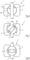
Figure 6 is a top plan view of the securement device ofFigure 2 with a catheter inserted through the transverse catheter insertion portion of the slot in the cap into the U-shaped catheter channel in the base; -
Figure 7 is a top plan view of the securement device ofFigure 6 with the screw cap partially rotated in a clockwise manner in the direction indicated by the arrows between the catheter receiving and catheter gripping positions; -
Figure 8 is a top plan view of the securement device ofFigure 6 with the screw cap fully rotated into the catheter gripping position; -
Figure 9 is a perspective view from above and one side of the securement device and catheter ofFigure 8 ; -
Figure 10 is a perspective view from above and one side of a second embodiment of the securement device in which the securement device has a secondary or pre-fixing clasp on the anchor pad for clasping and tidying the catheter in place on the securement device, and -
Figure 11 is a top plan view of the securement device ofFigure 10 . - As shown in
Figures 1 to 9 of the accompanying drawings, a first embodiment of asecurement device 1 in accordance with the invention for securely attaching a medical article such as acatheter 2 to a patient is generally made up of ananchor pad 3 for placing thesecurement device 1 on the patient, a base in the form of a substantiallycylindrical base 4 on theanchor pad 3 and ascrew cap 5 rotatably mountable on thebase 4 at a (screw) mounting 6 defined between thebase 4 and thescrew cap 5 between a catheter receiving position (shown inFigures 2 ,4 and6 ) and a catheter gripping position (shown inFigures 3 ,5 ,8 and9 ) in which radial pressure is applied to thecatheter 2 placed in thesecurement device 1 to securely hold thecatheter 2 and prevent micro-pistoning of thecatheter 2. Thescrew cap 5 can be moved repeatedly between the catheter receiving and catheter gripping positions so that thecatheter 2 can be positioned, secured, repositioned and re-secured as needed without requiring the use of adhesive plasters, dressings and the like. As a result, adhesive residues do not build up on thecatheter 2 so that the risk of infection is minimised and the structural integrity of thecatheter 2 is not compromised. - The
cylindrical base 4 is made up of acircular bottom wall 7 in contact with theanchor pad 3, asidewall 8 upstanding from thebottom wall 7 and a top face 9. The top face 9 is provided with a transverse U-shapedelongate channel 10 to sub-divide thesidewall 8 into afirst sidewall portion 11 and an oppositesecond sidewall portion 12. TheU-shaped channel 10 receives and holds acatheter 2 in thesecurement device 1 in use. - Externally, the first and
second sidewall portions like threads base 4 and thescrew cap 5. Eachthread upright thread portion 15 and a lowerhorizontal thread portion 16 contiguous with theupright thread portion 15. The lowerhorizontal portion 16 of eachthread screw cap 5 from free spinning on thebase 4 and to provide haptic feedback during rotatable engagement of thescrew cap 5 with thebase 4. This shall be explained more fully below. - The
screw cap 5 is complementary in size and shape with thebase 4 and has a circularlower rim 18 with acircular sidewall 19 upstanding therefrom towards atop wall 20. The circularlower rim 18 defines abase opening 21 into which thebase 4 is received by thescrew cap 5 during mounting of thescrew cap 5 on thebase 4. - A
tapered catheter slot 22 for receiving and gripping acatheter 2 is defined in thescrew cap sidewall 19 andtop wall 20. Thecatheter slot 22 is made up of a transversecatheter receiving portion 23 defined in thetop wall 20 complementary with the transverse U-shapedcatheter receiving channel 10 in thebase 4 and first and second oppositely disposed substantiallyhelical slot portions catheter 2 with a radial force defined in thesidewall 19. Thehelical slot portions upright slot element 26 and a substantiallyhorizontal slot element 27 contiguous with theupright slot element 26 defined in thecap sidewall 19. Thehorizontal slot elements 27 are continuously tapered towards aslot end 28 i.e. thecatheter slot 22 narrows towards theslot end 28 so that thesecurement device 1 can accommodate and securely gripcatheters 2, lines and the like of varying sizes in a jaw-like manner. - Internally, the
screw cap 5 is provided with two oppositely disposed lugs 29,30 on thesidewall 19. Thelugs base 4 and thecap 5. More particularly, thelugs helical threads sidewall 8 of thecylindrical base 4 to allow rotatable mounting of thescrew cap 5 on thebase 4. As indicated above, thestops 17 in the lowerhorizontal thread portion 16 abut thelugs screw cap 5 on thebase 4 and to provide haptic feedback when rotating thescrew cap 5 on thebase 4. The spaced apart stops 17 co-operate with thelugs screw cap 5 in position on thebase 4 and allow for thesecurement device 1 to be size adjusted in accordance with the size of catheter 2 (or other article) placed in thesecurement device 1. - Externally, the
screw cap 5 is provided with two oppositely disposed finger grips 31,32 on thescrew cap sidewall 19 to facilitate manual gripping and rotation of thescrew cap 5. - The
anchor pad 3 of thesecurement device 1 is of conventional construction and has anadhesive layer 33 for adhering theanchor pad 3 to a patient. Theadhesive layer 33 can be protected with a release film prior to use. - In use, the
anchor pad 3 with thebase 4 is placed on a patient'sskin 34 as required. With therotatable screw cap 5 in the catheter receiving position shown inFigures 2 and4 (i.e. with the transversecatheter receiving portion 23 of theslot 22 in thescrew cap 5 co-axially aligned with the transverse U-shapedcatheter receiving channel 10 in the base 4), acatheter 2 is inserted into the catheter receiving channel 10 (seeFigure 6 ). Thescrew cap 5 is then gripped by a clinician at thegrips Figures 7, 8 and9 . The oppositely disposed helicalcatheter slot portions catheter slot 22 therefore both slidably engage thecatheter 2 in a jaw-like manner to apply radial pressure to thecatheter 2 and securely grip thecatheter 2. Thecatheter 2 is therefore gripped twice at two spaced apart locations by thesecurement device 1. - As shown particularly in
Figures 4 and 5 , rotation of thescrew cap 5 on thebase 4 causes thelugs base 4 in the helical first andsecond threads screw cap 5 also applies a downward compressive force to thecatheter 2 to urge thecatheter 2 into theU-shaped channel 10 in thebase 4 to further enhance gripping of thecatheter 2. The downward distance, α, travelled by thescrew cap 5 on thebase 4, and hence the compressive force applied to thecatheter 2, is determined by the dimensions of the securement device. However, a distance, α, of about 2mm creates sufficient compressive force for most applications. - As indicated above, the
stops 17 on thebase 4 co-operate with thelugs base 4 and thescrew cap 5 whilst holding thescrew cap 5 in place on thebase 4 during application of the compressive force and providing haptic feedback during operation. - The above process is reversed in order to release the
catheter 2 without damage to thecatheter 2. -
Figures 9 and10 show a second embodiment of asecurement device 1 of the invention in which thesecurement device 1 has asecondary fixing clasp 35 on theanchor pad 3 for clasping and tidying a catheter 2 (not shown) in place on thesecurement device 1. Thecylindrical base 4 and thescrew cap 5 are as previously described in relation to thesecurement device 1 ofFigures 1 to 9 and like numerals indicate like parts. - In the present embodiment, the
anchor pad 3 is shaped and contoured to define a primaryanchor pad portion 36 on which thecylindrical base 4 of thesecurement device 1 is mounted and a secondaryanchor pad portion 37, on which thesecondary fixing clasp 35 is mounted, spaced apart from the primaryanchor pad portion 36. The primaryanchor pad portion 36 is connected with the secondaryanchor pad portion 37 by a wave-shaped anchorpad web portion 38 which extends between the primaryanchor pad portion 36 and the secondaryanchor pad portion 37 and spaces the fixing clasp 35 a set distance from thecylindrical base 4. - The fixing
clasp 35 has afastener 39 for detachably fastening a catheter, or other tubular article, in the fixingclasp 35. In the present embodiment, thefastener 39 is made up of two oppositely disposed push-fit notches clasp 35 for holding catheters and the like. Catheters and the like are therefore clasped in thesecondary fixing clasp 35 in addition to being secured between thebase 4 andscrew cap 5 of thesecurement device 1 so that the articles enjoy a double grip to further minimise movement of articles held in thesecurement device 1. - As indicated above, catheters and the like can be positioned and secured, repositioned and re-secured, repeatedly with the
securement device 1 without requiring the use of adhesive plasters, dressings and the like so that adhesive residues do not build-up on thecatheter 2. Use of thesecurement device 1 therefore minimises infection risk and ensures that the structural integrity of thecatheter 2 is maintained. - The improved grip achieved by the
securement device 1 of the invention prevents unwanted dislodgement of thecatheter 2 and micro-pistoning in use. - If desired, the
securement device 1 can be provided with a lock to prevent unauthorised or accidental release of the securement device e.g. outside a clinical setting or during movement. A suitable lock is a push to release lock incorporated into thesecurement device 1 requiring a pushing down action on thescrew cap 5 before rotation to release thescrew cap 5 from thebase 4. Suitable lock mechanisms are to be found in the child-proof locks of medicine bottles and the like. - As will be appreciated by those skilled in the art, although the
securement device 1 has been described in use with a catheter, thesecurement device 1 is suitable for use with a range of medical articles and particularly tubular medical articles such as catheters, lines, intravenous drips, surgical drains and cables such as E.C.G. cables. More generally, as indicated above, thesecurement device 1 is suitable for use with non-medical substantially tubular or cylindrical articles such as computer cabling, machine tubing, electrical cabling, hydraulic/pneumatic cabling and oil cabling where an effective (repositionable) grip is required that does not damage the articles and does not rely on the use of adhesives. Accordingly, the invention should not be construed as being limited to use with catheters only.
Claims (13)
- A securement device (1) for attaching an article (2) to a surface (34) comprising:an anchor pad (3) attachable to a surface (34);a base (4) on the anchor pad (3) for receiving the article (2), anda cap (5) mountable on the base (4) at a mounting (6) defined between the base (4) and the cap (5), the cap (5) being rotatable on the base (4) between an article receiving position and an article gripping position and the cap (5) comprising a slot (22) for receiving an article (2) in the article receiving position and gripping the article (2) in the article gripping position, characterised in that the slot (22) comprises first and second oppositely disposed substantially helical slot portions (24,25) in a sidewall (19) of the cap for gripping an article with a radial force in the article gripping position,wherein the helical slot portions (24,25) comprise an upright slot element (26) and a substantially horizontal slot element (27) contiguous with the upright slot element (26) in the sidewall (19), andwherein the substantially horizontal slot elements (27) continuously taper towards a slot end (28) in the sidewall.
- A securement device (1) as claimed in Claim 1 wherein the base (4) defines a channel (10) for receiving the article (2).
- A securement device (1) as claimed in Claim 1 or Claim 2 wherein the base (4) comprises a substantially cylindrical base (4).
- A securement device (1) as claimed in Claim 2 or Claim 3 wherein the slot (22) comprises an article receiving portion (23) complementary with the channel (10) for receiving the article (2) in the article receiving position.
- A securement device (1) as claimed in any of Claims 1 to 4 wherein the mounting (6) comprises a screw mounting (6) to impart a downward compressive force on an article (2) in the article gripping position.
- A securement device (1) as claimed in Claim 5 wherein the screw mounting (6) comprises a thread (13,14) on the base (4).
- A securement device (1) as claimed in Claim 6 wherein the thread (13,14) comprises first and second oppositely disposed substantially helical threads (13,14) on the base (4).
- A securement device (1) as claimed in Claim 6 or Claim 7 wherein the thread (13,14) comprises a groove-like thread (13,14).
- A securement device (1) as claimed in any of Claims 5 to 8 wherein the screw mounting (6) comprises at least one lug (29,30) on the cap (5) insertable in the thread (13,14).
- A securement device (1) as claimed in Claim 9 wherein the thread (13,14) further comprises at least one stop (17) abuttable against the at least one lug (29,30).
- A securement device (1) as claimed in any of Claims 1 to 10 further comprising a lock to prevent unauthorised or accidental release of the securement device (1).
- A securement device (1) as claimed in Claim 11 wherein the lock comprises a push to release lock in the cap (5).
- A securement device (1) as claimed in any of Claims 1 to 12 wherein the securement device (1) comprises a securement device (1) for attaching a medical article (2) to a patient.
Applications Claiming Priority (2)
| Application Number | Priority Date | Filing Date | Title |
|---|---|---|---|
| GB1811443.9A GB2575488A (en) | 2018-07-12 | 2018-07-12 | A securement device |
| PCT/EP2019/068012 WO2020011647A1 (en) | 2018-07-12 | 2019-07-04 | A securement device for pipes, cables or catheters |
Publications (3)
| Publication Number | Publication Date |
|---|---|
| EP3820555A1 EP3820555A1 (en) | 2021-05-19 |
| EP3820555C0 EP3820555C0 (en) | 2024-09-04 |
| EP3820555B1 true EP3820555B1 (en) | 2024-09-04 |
Family
ID=63273428
Family Applications (1)
| Application Number | Title | Priority Date | Filing Date |
|---|---|---|---|
| EP19744628.9A Active EP3820555B1 (en) | 2018-07-12 | 2019-07-04 | A securement device for pipes, cables or catheters |
Country Status (6)
| Country | Link |
|---|---|
| US (2) | US11896784B2 (en) |
| EP (1) | EP3820555B1 (en) |
| AU (1) | AU2019303334A1 (en) |
| ES (1) | ES2987789T3 (en) |
| GB (1) | GB2575488A (en) |
| WO (1) | WO2020011647A1 (en) |
Families Citing this family (8)
| Publication number | Priority date | Publication date | Assignee | Title |
|---|---|---|---|---|
| USD940878S1 (en) | 2020-05-05 | 2022-01-11 | Ortho Solutions, LC | Orthodontic post |
| US11273013B2 (en) * | 2020-05-05 | 2022-03-15 | Ortho Solutions, LC | Twist-lock orthodontic post |
| WO2022056376A1 (en) * | 2020-09-11 | 2022-03-17 | Medicametrix, Inc. | Infusion site retainer for maintaining infusion tubing |
| GB2599149B (en) * | 2020-09-28 | 2024-10-16 | Roberts David | Cord stopper and methods for using and manufacturing the same |
| USD991778S1 (en) * | 2022-01-21 | 2023-07-11 | Anthony Clark Blackburn | Cord tightening device |
| CN116531641B (en) * | 2023-05-05 | 2023-11-10 | 王兴 | Drainage tube fixing device |
| CN118455001B (en) * | 2024-07-10 | 2024-10-01 | 江苏宁美新能源有限公司 | Dispensing equipment for photovoltaic module production and production process thereof |
| CN118793846B (en) * | 2024-09-12 | 2024-11-22 | 山西省安装集团股份有限公司 | Industrial pipeline installation device |
Family Cites Families (13)
| Publication number | Priority date | Publication date | Assignee | Title |
|---|---|---|---|---|
| US3624673A (en) * | 1969-11-19 | 1971-11-30 | Ethyl Dev Corp | Double-ended plastic clothespin |
| US6224571B1 (en) | 1997-11-14 | 2001-05-01 | Venetec International, Inc. | Medical line securement device |
| JP2005523781A (en) | 2002-05-01 | 2005-08-11 | ベネテック インターナショナル インコーポレイテッド | Medical line fixation device |
| US20050033268A1 (en) * | 2003-08-06 | 2005-02-10 | Kimberly-Clark Worldwide, Inc. | Connector with protrusion adapted for interconnection with second member |
| EP2337598A4 (en) | 2008-09-19 | 2012-06-20 | Bard Inc C R | Medical device securement system |
| US8394067B2 (en) | 2009-05-21 | 2013-03-12 | C.R. Bard, Inc. | Medical device securement system |
| US8740852B2 (en) | 2009-08-25 | 2014-06-03 | C. R. Bard, Inc. | Medical article securement device |
| JP2013507186A (en) * | 2009-10-06 | 2013-03-04 | ヴェネテック・インターナショナル,インコーポレーテッド | Stabilization device with snap clamp |
| GB201113785D0 (en) | 2011-08-10 | 2011-09-21 | Hybrand Medical Ltd | Medical line securement system |
| JP5818613B2 (en) * | 2011-09-28 | 2015-11-18 | 日本コヴィディエン株式会社 | Catheter fixture |
| JP5818614B2 (en) * | 2011-09-28 | 2015-11-18 | 日本コヴィディエン株式会社 | Catheter fixture |
| FR3051118A1 (en) * | 2016-05-11 | 2017-11-17 | Cedric Delage | DEVICE FOR IMMOBILIZING TUBULES AND ASSEMBLY COMPRISING SAME |
| US12083291B2 (en) * | 2018-04-09 | 2024-09-10 | Regents Of The University Of Minnesota | Anchoring devices for implanted tubes and related methods |
-
2018
- 2018-07-12 GB GB1811443.9A patent/GB2575488A/en not_active Withdrawn
-
2019
- 2019-07-04 EP EP19744628.9A patent/EP3820555B1/en active Active
- 2019-07-04 WO PCT/EP2019/068012 patent/WO2020011647A1/en not_active Ceased
- 2019-07-04 US US17/259,490 patent/US11896784B2/en active Active
- 2019-07-04 ES ES19744628T patent/ES2987789T3/en active Active
- 2019-07-04 AU AU2019303334A patent/AU2019303334A1/en not_active Abandoned
-
2024
- 2024-01-05 US US18/405,743 patent/US20240139476A1/en active Pending
Also Published As
| Publication number | Publication date |
|---|---|
| WO2020011647A1 (en) | 2020-01-16 |
| EP3820555C0 (en) | 2024-09-04 |
| US20210316118A1 (en) | 2021-10-14 |
| GB2575488A (en) | 2020-01-15 |
| US20240139476A1 (en) | 2024-05-02 |
| GB201811443D0 (en) | 2018-08-29 |
| ES2987789T3 (en) | 2024-11-18 |
| US11896784B2 (en) | 2024-02-13 |
| EP3820555A1 (en) | 2021-05-19 |
| AU2019303334A1 (en) | 2021-01-21 |
Similar Documents
| Publication | Publication Date | Title |
|---|---|---|
| US20240139476A1 (en) | Securement device for pipes, cables or catheters | |
| US9931488B2 (en) | Holding devices for elongated instruments | |
| US8211063B2 (en) | Side loaded securement device | |
| CA2235157C (en) | Introducer device and methods of use thereof | |
| CA2177610C (en) | Retention bolsters for percutaneous catheters | |
| US4874380A (en) | Catheter retaining device | |
| US8277420B2 (en) | Securement device with toggle clamp mechanism | |
| AU2020357487B2 (en) | Anti-rotation catheter devices and systems | |
| US20190076628A1 (en) | Splittable catheter insertion device and related methods | |
| US20100324491A1 (en) | Securement device | |
| US20130345639A1 (en) | Securement device | |
| CN207125944U (en) | With the needle device that can adjust holder | |
| EP0274418A2 (en) | Catheter retaining device | |
| US20230398332A1 (en) | Guidewire safety device | |
| JPWO2001023021A1 (en) | Winged injection needle with needle shielding means | |
| US7549200B2 (en) | Clamp for flexible tube | |
| CA3095072C (en) | Needleless connector loosening device | |
| JP7850734B2 (en) | Catheter traction device, system, and method | |
| AU2021255458B2 (en) | Catheter adapter push tab and related devices, systems |
Legal Events
| Date | Code | Title | Description |
|---|---|---|---|
| STAA | Information on the status of an ep patent application or granted ep patent |
Free format text: STATUS: UNKNOWN |
|
| STAA | Information on the status of an ep patent application or granted ep patent |
Free format text: STATUS: THE INTERNATIONAL PUBLICATION HAS BEEN MADE |
|
| PUAI | Public reference made under article 153(3) epc to a published international application that has entered the european phase |
Free format text: ORIGINAL CODE: 0009012 |
|
| STAA | Information on the status of an ep patent application or granted ep patent |
Free format text: STATUS: REQUEST FOR EXAMINATION WAS MADE |
|
| 17P | Request for examination filed |
Effective date: 20210208 |
|
| AK | Designated contracting states |
Kind code of ref document: A1 Designated state(s): AL AT BE BG CH CY CZ DE DK EE ES FI FR GB GR HR HU IE IS IT LI LT LU LV MC MK MT NL NO PL PT RO RS SE SI SK SM TR |
|
| RIN1 | Information on inventor provided before grant (corrected) |
Inventor name: O'SULLIVAN, AIDAN G. Inventor name: O'SULLIVAN, LEONARD W. Inventor name: WHITE, EOIN J. Inventor name: DELOUGHRY, NIALL Inventor name: STACK, AUSTIN |
|
| DAV | Request for validation of the european patent (deleted) | ||
| DAX | Request for extension of the european patent (deleted) | ||
| STAA | Information on the status of an ep patent application or granted ep patent |
Free format text: STATUS: EXAMINATION IS IN PROGRESS |
|
| 17Q | First examination report despatched |
Effective date: 20230817 |
|
| GRAP | Despatch of communication of intention to grant a patent |
Free format text: ORIGINAL CODE: EPIDOSNIGR1 |
|
| STAA | Information on the status of an ep patent application or granted ep patent |
Free format text: STATUS: GRANT OF PATENT IS INTENDED |
|
| INTG | Intention to grant announced |
Effective date: 20240603 |
|
| GRAS | Grant fee paid |
Free format text: ORIGINAL CODE: EPIDOSNIGR3 |
|
| GRAA | (expected) grant |
Free format text: ORIGINAL CODE: 0009210 |
|
| STAA | Information on the status of an ep patent application or granted ep patent |
Free format text: STATUS: THE PATENT HAS BEEN GRANTED |
|
| AK | Designated contracting states |
Kind code of ref document: B1 Designated state(s): AL AT BE BG CH CY CZ DE DK EE ES FI FR GB GR HR HU IE IS IT LI LT LU LV MC MK MT NL NO PL PT RO RS SE SI SK SM TR |
|
| REG | Reference to a national code |
Ref country code: GB Ref legal event code: FG4D |
|
| REG | Reference to a national code |
Ref country code: CH Ref legal event code: EP |
|
| REG | Reference to a national code |
Ref country code: IE Ref legal event code: FG4D |
|
| REG | Reference to a national code |
Ref country code: DE Ref legal event code: R096 Ref document number: 602019058295 Country of ref document: DE |
|
| U01 | Request for unitary effect filed |
Effective date: 20240924 |
|
| REG | Reference to a national code |
Ref country code: ES Ref legal event code: FG2A Ref document number: 2987789 Country of ref document: ES Kind code of ref document: T3 Effective date: 20241118 |
|
| U07 | Unitary effect registered |
Designated state(s): AT BE BG DE DK EE FI FR IT LT LU LV MT NL PT RO SE SI Effective date: 20241017 |
|
| PG25 | Lapsed in a contracting state [announced via postgrant information from national office to epo] |
Ref country code: NO Free format text: LAPSE BECAUSE OF FAILURE TO SUBMIT A TRANSLATION OF THE DESCRIPTION OR TO PAY THE FEE WITHIN THE PRESCRIBED TIME-LIMIT Effective date: 20241204 |
|
| PG25 | Lapsed in a contracting state [announced via postgrant information from national office to epo] |
Ref country code: GR Free format text: LAPSE BECAUSE OF FAILURE TO SUBMIT A TRANSLATION OF THE DESCRIPTION OR TO PAY THE FEE WITHIN THE PRESCRIBED TIME-LIMIT Effective date: 20241205 Ref country code: PL Free format text: LAPSE BECAUSE OF FAILURE TO SUBMIT A TRANSLATION OF THE DESCRIPTION OR TO PAY THE FEE WITHIN THE PRESCRIBED TIME-LIMIT Effective date: 20240904 |
|
| PG25 | Lapsed in a contracting state [announced via postgrant information from national office to epo] |
Ref country code: HR Free format text: LAPSE BECAUSE OF FAILURE TO SUBMIT A TRANSLATION OF THE DESCRIPTION OR TO PAY THE FEE WITHIN THE PRESCRIBED TIME-LIMIT Effective date: 20240904 |
|
| PG25 | Lapsed in a contracting state [announced via postgrant information from national office to epo] |
Ref country code: RS Free format text: LAPSE BECAUSE OF FAILURE TO SUBMIT A TRANSLATION OF THE DESCRIPTION OR TO PAY THE FEE WITHIN THE PRESCRIBED TIME-LIMIT Effective date: 20241204 |
|
| PG25 | Lapsed in a contracting state [announced via postgrant information from national office to epo] |
Ref country code: RS Free format text: LAPSE BECAUSE OF FAILURE TO SUBMIT A TRANSLATION OF THE DESCRIPTION OR TO PAY THE FEE WITHIN THE PRESCRIBED TIME-LIMIT Effective date: 20241204 Ref country code: PL Free format text: LAPSE BECAUSE OF FAILURE TO SUBMIT A TRANSLATION OF THE DESCRIPTION OR TO PAY THE FEE WITHIN THE PRESCRIBED TIME-LIMIT Effective date: 20240904 Ref country code: NO Free format text: LAPSE BECAUSE OF FAILURE TO SUBMIT A TRANSLATION OF THE DESCRIPTION OR TO PAY THE FEE WITHIN THE PRESCRIBED TIME-LIMIT Effective date: 20241204 Ref country code: HR Free format text: LAPSE BECAUSE OF FAILURE TO SUBMIT A TRANSLATION OF THE DESCRIPTION OR TO PAY THE FEE WITHIN THE PRESCRIBED TIME-LIMIT Effective date: 20240904 Ref country code: GR Free format text: LAPSE BECAUSE OF FAILURE TO SUBMIT A TRANSLATION OF THE DESCRIPTION OR TO PAY THE FEE WITHIN THE PRESCRIBED TIME-LIMIT Effective date: 20241205 |
|
| PG25 | Lapsed in a contracting state [announced via postgrant information from national office to epo] |
Ref country code: IS Free format text: LAPSE BECAUSE OF FAILURE TO SUBMIT A TRANSLATION OF THE DESCRIPTION OR TO PAY THE FEE WITHIN THE PRESCRIBED TIME-LIMIT Effective date: 20250104 |
|
| PG25 | Lapsed in a contracting state [announced via postgrant information from national office to epo] |
Ref country code: SM Free format text: LAPSE BECAUSE OF FAILURE TO SUBMIT A TRANSLATION OF THE DESCRIPTION OR TO PAY THE FEE WITHIN THE PRESCRIBED TIME-LIMIT Effective date: 20240904 |
|
| PG25 | Lapsed in a contracting state [announced via postgrant information from national office to epo] |
Ref country code: CZ Free format text: LAPSE BECAUSE OF FAILURE TO SUBMIT A TRANSLATION OF THE DESCRIPTION OR TO PAY THE FEE WITHIN THE PRESCRIBED TIME-LIMIT Effective date: 20240904 |
|
| PG25 | Lapsed in a contracting state [announced via postgrant information from national office to epo] |
Ref country code: SK Free format text: LAPSE BECAUSE OF FAILURE TO SUBMIT A TRANSLATION OF THE DESCRIPTION OR TO PAY THE FEE WITHIN THE PRESCRIBED TIME-LIMIT Effective date: 20240904 |
|
| PLBE | No opposition filed within time limit |
Free format text: ORIGINAL CODE: 0009261 |
|
| STAA | Information on the status of an ep patent application or granted ep patent |
Free format text: STATUS: NO OPPOSITION FILED WITHIN TIME LIMIT |
|
| 26N | No opposition filed |
Effective date: 20250605 |
|
| U20 | Renewal fee for the european patent with unitary effect paid |
Year of fee payment: 7 Effective date: 20250730 |
|
| PGFP | Annual fee paid to national office [announced via postgrant information from national office to epo] |
Ref country code: ES Payment date: 20250815 Year of fee payment: 7 |
|
| PGFP | Annual fee paid to national office [announced via postgrant information from national office to epo] |
Ref country code: GB Payment date: 20250717 Year of fee payment: 7 |
|
| PGFP | Annual fee paid to national office [announced via postgrant information from national office to epo] |
Ref country code: IE Payment date: 20250724 Year of fee payment: 7 |
|
| REG | Reference to a national code |
Ref country code: CH Ref legal event code: H13 Free format text: ST27 STATUS EVENT CODE: U-0-0-H10-H13 (AS PROVIDED BY THE NATIONAL OFFICE) Effective date: 20260224 |
|
| PG25 | Lapsed in a contracting state [announced via postgrant information from national office to epo] |
Ref country code: CH Free format text: LAPSE BECAUSE OF NON-PAYMENT OF DUE FEES Effective date: 20250731 |