EP3820102A1 - Ambiguity/aliasing cancellation or reduction for staggered reference signals - Google Patents

Ambiguity/aliasing cancellation or reduction for staggered reference signals Download PDF

Info

Publication number
EP3820102A1
EP3820102A1 EP19209790.5A EP19209790A EP3820102A1 EP 3820102 A1 EP3820102 A1 EP 3820102A1 EP 19209790 A EP19209790 A EP 19209790A EP 3820102 A1 EP3820102 A1 EP 3820102A1
Authority
EP
European Patent Office
Prior art keywords
srs
ofdm symbol
comb
sequence
correction factor
Prior art date
Legal status (The legal status is an assumption and is not a legal conclusion. Google has not performed a legal analysis and makes no representation as to the accuracy of the status listed.)
Withdrawn
Application number
EP19209790.5A
Other languages
German (de)
French (fr)
Inventor
Mohammad Alawieh
Marcus Grossmann
Birendra GHIMIRE
Ernst Eberlein
Current Assignee (The listed assignees may be inaccurate. Google has not performed a legal analysis and makes no representation or warranty as to the accuracy of the list.)
Fraunhofer Gesellschaft zur Foerderung der Angewandten Forschung eV
Original Assignee
Fraunhofer Gesellschaft zur Foerderung der Angewandten Forschung eV
Priority date (The priority date is an assumption and is not a legal conclusion. Google has not performed a legal analysis and makes no representation as to the accuracy of the date listed.)
Filing date
Publication date
Application filed by Fraunhofer Gesellschaft zur Foerderung der Angewandten Forschung eV filed Critical Fraunhofer Gesellschaft zur Foerderung der Angewandten Forschung eV
Priority to EP20799756.0A priority Critical patent/EP4055789B1/en
Priority to PCT/EP2020/081187 priority patent/WO2021089732A1/en
Priority to CN202080092001.7A priority patent/CN114946162B/en
Publication of EP3820102A1 publication Critical patent/EP3820102A1/en
Priority to US17/731,493 priority patent/US12267197B2/en
Withdrawn legal-status Critical Current

Links

Images

Classifications

    • HELECTRICITY
    • H04ELECTRIC COMMUNICATION TECHNIQUE
    • H04LTRANSMISSION OF DIGITAL INFORMATION, e.g. TELEGRAPHIC COMMUNICATION
    • H04L27/00Modulated-carrier systems
    • H04L27/26Systems using multi-frequency codes
    • H04L27/2601Multicarrier modulation systems
    • H04L27/2602Signal structure
    • H04L27/261Details of reference signals
    • H04L27/2613Structure of the reference signals
    • HELECTRICITY
    • H04ELECTRIC COMMUNICATION TECHNIQUE
    • H04LTRANSMISSION OF DIGITAL INFORMATION, e.g. TELEGRAPHIC COMMUNICATION
    • H04L27/00Modulated-carrier systems
    • H04L27/26Systems using multi-frequency codes
    • H04L27/2601Multicarrier modulation systems
    • H04L27/2614Peak power aspects
    • H04L27/2621Reduction thereof using phase offsets between subcarriers
    • GPHYSICS
    • G01MEASURING; TESTING
    • G01SRADIO DIRECTION-FINDING; RADIO NAVIGATION; DETERMINING DISTANCE OR VELOCITY BY USE OF RADIO WAVES; LOCATING OR PRESENCE-DETECTING BY USE OF THE REFLECTION OR RERADIATION OF RADIO WAVES; ANALOGOUS ARRANGEMENTS USING OTHER WAVES
    • G01S5/00Position-fixing by co-ordinating two or more direction or position line determinations; Position-fixing by co-ordinating two or more distance determinations
    • G01S5/02Position-fixing by co-ordinating two or more direction or position line determinations; Position-fixing by co-ordinating two or more distance determinations using radio waves
    • G01S5/0205Details
    • G01S5/0215Interference
    • HELECTRICITY
    • H04ELECTRIC COMMUNICATION TECHNIQUE
    • H04LTRANSMISSION OF DIGITAL INFORMATION, e.g. TELEGRAPHIC COMMUNICATION
    • H04L27/00Modulated-carrier systems
    • H04L27/26Systems using multi-frequency codes
    • H04L27/2601Multicarrier modulation systems
    • H04L27/2602Signal structure
    • HELECTRICITY
    • H04ELECTRIC COMMUNICATION TECHNIQUE
    • H04WWIRELESS COMMUNICATION NETWORKS
    • H04W72/00Local resource management
    • H04W72/04Wireless resource allocation
    • H04W72/044Wireless resource allocation based on the type of the allocated resource
    • H04W72/0453Resources in frequency domain, e.g. a carrier in FDMA
    • GPHYSICS
    • G01MEASURING; TESTING
    • G01SRADIO DIRECTION-FINDING; RADIO NAVIGATION; DETERMINING DISTANCE OR VELOCITY BY USE OF RADIO WAVES; LOCATING OR PRESENCE-DETECTING BY USE OF THE REFLECTION OR RERADIATION OF RADIO WAVES; ANALOGOUS ARRANGEMENTS USING OTHER WAVES
    • G01S5/00Position-fixing by co-ordinating two or more direction or position line determinations; Position-fixing by co-ordinating two or more distance determinations
    • G01S5/02Position-fixing by co-ordinating two or more direction or position line determinations; Position-fixing by co-ordinating two or more distance determinations using radio waves
    • G01S5/06Position of source determined by co-ordinating a plurality of position lines defined by path-difference measurements

Definitions

  • the present application relates to the field of wireless communication systems or networks, more specifically to enhancements or improvements regarding reference signals to be employed in the wireless communication system or network for various purposes.
  • Embodiments of the present invention concern approaches for an ambiguity/aliasing reduction or cancellation for staggered reference signals, like positioning reference signals used for determining positions of one or more entities in the wireless communication system or network.
  • Fig. 1 is a schematic representation of an example of a terrestrial wireless network 100 including, as is shown in Fig. 1(a) , a core network 102 and one or more radio access networks RAN 1 , RAN 2 , ...RAN N .
  • Fig. 1(b) is a schematic representation of an example of a radio access network RAN n that may include one or more base stations gNB 1 to gNB 5 , each serving a specific area surrounding the base station schematically represented by respective cells 106 1 to 106 5 .
  • the base stations are provided to serve users within a cell.
  • the one or more base stations may serve users in licensed and/or unlicensed bands.
  • base station refers to a gNB in 5G networks, an eNB in UMTS/LTE/LTE-A/ LTE-A Pro, or just a BS in other mobile communication standards.
  • a user may be a stationary device or a mobile device.
  • the wireless communication system may also be accessed by mobile or stationary loT devices which connect to a base station or to a user.
  • the mobile devices or the loT devices may include physical devices, ground based vehicles, such as robots or cars, aerial vehicles, such as manned or unmanned aerial vehicles (UAVs), the latter also referred to as drones, buildings and other items or devices having embedded therein electronics, software, sensors, actuators, or the like as well as network connectivity that enables these devices to collect and exchange data across an existing network infrastructure.
  • Fig. 1(b) shows an exemplary view of five cells, however, the RAN n may include more or less such cells, and RAN n may also include only one base station.
  • Fig. 1(b) shows two users UE 1 and UE 2 , also referred to as user equipment, UE, that are in cell 106 2 and that are served by base station gNB 2 .
  • FIG. 1(b) shows two loT devices 110 1 and 110 2 in cell 106 4 , which may be stationary or mobile devices.
  • the loT device 110 1 accesses the wireless communication system via the base station gNB 4 to receive and transmit data as schematically represented by arrow 112 1 .
  • the loT device 110 2 accesses the wireless communication system via the user UE 3 as is schematically represented by arrow 112 2 .
  • the respective base station gNB 1 to gNB 5 may be connected to the core network 102, e.g. via the S1 interface, via respective backhaul links 114 1 to 114 5 , which are schematically represented in Fig. 1(b) by the arrows pointing to "core".
  • the core network 102 may be connected to one or more external networks. Further, some or all of the respective base station gNB 1 to gNB 5 may be connected, e.g.
  • a sidelink channel allows direct communication between UEs, also referred to as device-to-device (D2D) communication.
  • D2D device-to-device
  • the sidelink interface in 3GPP is named PC5.
  • the physical resource grid may comprise a set of resource elements to which various physical channels and physical signals are mapped.
  • the physical channels may include the physical downlink, uplink and sidelink shared channels (PDSCH, PUSCH, PSSCH) carrying user specific data, also referred to as downlink, uplink and sidelink payload data, the physical broadcast channel (PBCH) carrying for example a master information block (MIB) and one or more of a system information block (SIB), the physical downlink, uplink and sidelink control channels (PDCCH, PUCCH, PSSCH) carrying for example the downlink control information (DCI), the uplink control information (UCI) and the sidelink control information (SCI).
  • the sidelink interface may a support 2-stage SCI. This refers to a first control region containing some parts of the SCI, and optionally, a second control region, which contains a second part of control information.
  • the physical channels may further include the physical random access channel (PRACH or RACH) used by UEs for accessing the network once a UE synchronized and obtained the MIB and SIB.
  • the physical signals may comprise reference signals or symbols (RS), synchronization signals and the like.
  • the resource grid may comprise a frame or radio frame having a certain duration in the time domain and having a given bandwidth in the frequency domain.
  • the frame may have a certain number of subframes of a predefined length, e.g. 1ms. Each subframe may include one or more slots of 12 or 14 OFDM symbols depending on the cyclic prefix (CP) length.
  • a frame may also consist of a smaller number of OFDM symbols, e.g. when utilizing shortened transmission time intervals (sTTI) or a mini-slot/non-slot-based frame structure comprising just a few OFDM symbols.
  • sTTI shortened transmission time intervals
  • mini-slot/non-slot-based frame structure comprising just
  • the wireless communication system may be any single-tone or multicarrier system using frequency-division multiplexing, like the orthogonal frequency-division multiplexing (OFDM) system, the orthogonal frequency-division multiple access (OFDMA) system, or any other IFFT-based signal with or without CP, e.g. DFT-s-OFDM.
  • Other waveforms like non-orthogonal waveforms for multiple access, e.g. filter-bank multicarrier (FBMC), generalized frequency division multiplexing (GFDM) or universal filtered multi carrier (UFMC), may be used.
  • the wireless communication system may operate, e.g., in accordance with the LTE-Advanced pro standard, or the 5G or NR, New Radio, standard, or the NR-U, New Radio Unlicensed, standard.
  • the wireless network or communication system depicted in Fig. 1 may be a heterogeneous network having distinct overlaid networks, e.g., a network of macro cells with each macro cell including a macro base station, like base station gNB 1 to gNB 5 , and a network of small cell base stations (not shown in Fig. 1 ), like femto or pico base stations.
  • a network of macro cells with each macro cell including a macro base station, like base station gNB 1 to gNB 5 , and a network of small cell base stations (not shown in Fig. 1 ), like femto or pico base stations.
  • non-terrestrial wireless communication networks including spaceborne transceivers, like satellites, and/or airborne transceivers, like unmanned aircraft systems.
  • the non-terrestrial wireless communication network or system may operate in a similar way as the terrestrial system described above with reference to Fig. 1 , for example in accordance with the LTE-Advanced Pro standard or the 5G or NR, new radio, standard.
  • various reference signals may be used, e.g., downlink reference signals, uplink reference signals, synchronization signals or positioning reference signals, PRS.
  • the downlink reference signals may have a two-dimensional reference-signal sequence, which indicates the cell identity.
  • the uplink reference signals may include demodulation reference signals, DM-RS, and sounding reference signals, SRSs.
  • the synchronization signals may include the primary synchronization sequence, PSS, and the secondary synchronization sequence, SSS.
  • the positioning reference signal may be used to determine the location of an entity based on radio access network information.
  • the respective entities may employ reference signals for various purposes.
  • the use of such reference signals by the respective entities is described with reference to a positioning application for identifying positions of multiple UEs employing SRS transmissions.
  • the present invention is not limited to such implementations.
  • Embodiments of the present invention are applicable to any reference signal employed in the wireless communication signal, e.g., reference signals used in the UL or in the DL or in the sidelink, SL.
  • Fig. 2 illustrates a scenario for positioning applications.
  • Fig. 2 may be a part or a wireless communication system or network as described above with reference to Fig. 1 , like a 4G or 5G network, and shows four UE, UE1 to UE4, as well as four serving base stations, s-gNB1 to s-gNB4, serving the respective UEs.
  • s-gNB1 serving base stations
  • s-gNB4 serving the respective UEs.
  • each of the UEs is synchronized to its s-gNB.
  • a time at which a transmission is made is adjusted by the timing advance, TA, so that signals from different UEs being derived by the s-gNB arrive at the s-gNB aligned with each other, i.e., aligned to the framing of the s-gNB.
  • a UE is logged in at or is served by the s-gNB to which the UE has the shortest distance.
  • the TA is adjusted according to the distance between the UE and the s-gNB.
  • multiple s-gNBs need to receive a signal, like an SRS signal, from a respective UE, as indicated by the single-headed arrows in Fig. 2 , so that, according to the respective distances of a UE to the s-gNBs, the signals arrive at different times. From this difference in time of arrival, TOA, the position of the transmitter, the UE, may be determined.
  • Fig. 3 schematically illustrate the timing or temporal behavior of such SRS signals in case there are one transmitter and three receivers.
  • the s-gNBs are synchronized, i.e., the framing of the s-gNBs is synchronized and the signal processing is synchronized to this framing.
  • the OFDM symbol timing is synchronized.
  • a transmitter is considered and the ToA is indicated for different receivers, like ToA1 ... ToA3 in Fig. 3 .
  • the transmission time needs to be known.
  • An exact synchronization of the transmission time, the Time-of-Transmit, ToT is therefore not necessary.
  • An OFDM demodulator usually uses only the payload symbol. The so-called cyclic prefix is removed before further processing.
  • an exact synchronization is not necessary.
  • a non-ideal synchronization of the symbol timing of the demodulator usually means only a slight reduction of the SINR. Since a low SINR is sufficient anyway for the ToA determination, an exact synchronization of the demodulator may therefore be dispensed with.
  • a coarse synchronization according to the principles of TA is sufficient.
  • Fig. 4 illustrates a scenario in which three UEs send to one receiver in the same time slot. According to the TA settings and the distance the signals arrive with a time delay at a receiver. The time difference is relatively small compared to the OFDM symbol duration. The relevant signal part for further processing signals indicated by the OFDM symbol window. Besides the advantage of the multiple use of an REs, this results in another advantage: The signals maybe processed substantially in parallel by an OFDM demodulator and are only separated after the OFDM demodulation.
  • Fig. 5 illustrates an effective correlation peak without cyclic shift ( Fig. 5(a) ) and with cyclic shift ( Fig. 5(b) ).
  • the correlation peaks may be uniquely allocated if the distance differences are smaller than 1.6km. That may be enough for many applications, and for a non-ideal TA the value may be reduced accordingly. For larger cyclic shift steps, i.e., fewer UEs are multiplexed, the range of values increases.
  • the resource elements, REs, in the time-frequency may be allocated to different UEs for SRS transmission.
  • the channel impulse response of the full assigned bandwidth may be obtained if all subcarriers within the assigned bandwidth are used.
  • FIG. 6 illustrates the allocation of REs for the transmission of the SRS with four OFDM symbols sym1, sym2, sym3, sym4 and a transmission COMB factor of 4, i.e., every fourth subcarrier is used for the SRS transmission.
  • a transmission COMB factor of 4 i.e., every fourth subcarrier is used for the SRS transmission.
  • the overall energy used for the SRS transmission is increased if the number of symbols in increase ( Fig. 6 ), thereby enlarging the coverage range of SRS transmissions.
  • FIG. 7 illustrates the principle of staggering/de-staggering.
  • Fig. 7(a) illustrates the allocation of the REs for the transmission of SRS with one OFDM symbol sym1.
  • Fig. 7(b) illustrates the staggering of the SRS REs of Fig. 7(a) in the time and frequency domains, and
  • Fig. 7(c) illustrates the de-staggering of the SRS REs of Fig. 7(b) .
  • the REs for the transmission of the SRS are distributed over the four OFDM symbols sym1, sym2, sym3, sym4 with a transmission COMB factor of 4 in each symbol. Further, different offsets are assigned to the transmissions in subsequent OFDM symbols with respect to the first symbol sym1.
  • the offset for the REs in the second symbol sym2 is one RE with respect to the first symbol sym1
  • the offset for the REs in the third symbol sym3 is two REs with respect to the first symbol sym1
  • the offset for the REs in the fourth symbol sym4 is three REs with respect to the first symbol sym1.
  • the available transmit power is one of the limiting factors in reaching multiple TRPs and using the transmission comb is an efficient method to concentrate the available transmit power on the reduced number of subcarriers, while maintaining the overall bandwidth.
  • the former achieves the goal of power boosting and the latter maintains the time resolution.
  • the de-staggered reference signals include an ambiguity/aliasing because the correlation peaks repeat at a distance given by NFFT / K TC , where N FFT is the size of the FFT and K TC is the COMB factor. This ambiguity/aliasing limits the separating of multiple users efficiently.
  • the downside of using transmission comb is that the aliases of correlation peaks occur.
  • the correlation peaks repeat at a distance given by NFFT/KTC, where NFFT is the size of FFT and KTC is the comb factor. This provides a basic limitation in separating multiple users efficiently.
  • TDOC R1-1911229 On approach partly addressing the issue of above discussed ambiguity/aliasing is described in TDOC R1-1911229 and suggests to generate a modified sequence for each OFDM symbol so as to ensure phase continuity is ensured.
  • different base sequences are to be used for each symbol.
  • this requires generating a specific sequence for each symbol increasing the processing overhead and, thereby also the power consumption, and, since the number of sequences that is actually supported remains the same, i.e., is not increased, the flexibility is low.
  • the present invention provides improvements and enhancements in a wireless communication system or network addressing the above described issue, while avoiding the drawbacks of conventional approaches addressing this issue.
  • the present invention provides approaches for reducing or canceling an ambiguity/aliasing of staggered reference signals after de-staggering them, like positioning reference signals used for determining positions of multiple entities in the wireless communication system or network.
  • the phase offset correction is applied to OFDM symbols belonging to the same SRS resource so that the symbols may be coherently added, thereby reducing or canceling the ambiguity/aliasing of staggered reference signals after de-staggering them.
  • the inventive approach provides the following improvements:
  • the inventive approach is advantageous as it supports a higher effective delay range of the cyclic shift, allows a small step size and minimizes the required modification to Rel. 15.
  • Embodiments of the inventive approach allow the distribution of the REs assigned to one UE or gNB to several symbols, and improves the cross-correlation properties of the received signal thereby allowing for a better separation of the signals transmitted from different UEs or gNBs. With better cross-correlation properties more UEs or gNBs may share the same REs.
  • Embodiments of the present invention may be implemented in a wireless communication system as depicted in Fig. 1 including base stations and users, like mobile terminals or loT devices.
  • Fig. 10 is a schematic representation of a wireless communication system including a transmitter 300, like a base station, and one or more receivers 302, 304, like user devices, UEs.
  • the transmitter 300 and the receivers 302, 304 may communicate via one or more wireless communication links or channels 306a, 306b, 308, like a radio link.
  • the transmitter 300 may include one or more antennas ANT T or an antenna array having a plurality of antenna elements, a signal processor 300a and a transceiver 300b, coupled with each other.
  • the receivers 302, 304 include one or more antennas ANT UE or an antenna array having a plurality of antennas, a signal processor 302a, 304a, and a transceiver 302b, 304b coupled with each other.
  • the base station 300 and the UEs 302, 304 may communicate via respective first wireless communication links 306a and 306b, like a radio link using the Uu interface, while the UEs 302, 304 may communicate with each other via a second wireless communication link 308, like a radio link using the PC5/sidelink (SL) interface.
  • SL PC5/sidelink
  • the UEs When the UEs are not served by the base station, are not be connected to a base station, for example, they are not in an RRC connected state, or, more generally, when no SL resource allocation configuration or assistance is provided by a base station, the UEs may communicate with each other over the sidelink (SL).
  • the system or network of Fig. 10 , the one or more UEs 302, 304 of Fig. 10 , and the base station 300 of Fig. 10 may operate in accordance with the inventive teachings described herein.
  • the present invention provides (see for example claim 1) an apparatus for a wireless communication system, wherein the apparatus is to transmit a reference signal on a common set of resource elements, REs, the common set of REs used by one or more further apparatuses in the wireless communication system to transmit the reference signal so that the reference signals of the apparatus and of the one or more further apparatuses use the same REs,
  • the apparatus is to transmit the reference signal on a common set of REs used by one or more antenna ports of the apparatus to transmit the reference signal, and wherein for each antenna port a different cyclic shift may be used.
  • the resource or resource set of the reference signal is configured so that the apparatuses are distinguished by a first correction factor, and wherein the antenna ports of the apparatus are distinguished by second correction factor, the first correction factor implementing a coarser cyclic shift then the second correction factor.
  • the apparatus is configured with n SRS effcs , i or a i via a higher layer, e.g., using RRC signaling, or via the physical layer.
  • K TC transmission comb value, k 0 p i frequency domain starting position for antenna port p i , l 0 index of OFDM symbol within the slot containing where the SRS transmission starts, ⁇ k ( p i ,l ') relative comb offset value of the l '-th SRS OFDM for antenna port p i , N AP number of the antenna ports, ⁇ SRS amplitude scaling factor to adjust transmit power, M sc , b RS the number of resource blocks used for transmitting SRS N symb SRS number of SRS symbols within a resource, or wherein the apparatus is to apply the correction factor e j ⁇ c to the sequence r ( p i )( n , l ') such that the phase-corrected OFDM symbol before mapping on the time frequency resources is given by r ⁇ p i n l ⁇ e j ⁇ ⁇ i , ⁇ k p i l ⁇ , K
  • the sequence is a sounding reference signal, SRS, sequence or a positioning reference signal, PRS, sequence.
  • the apparatus comprises a user device, UE, the UE comprising one or more of: a mobile terminal, a stationary terminal, a cellular IoT-UE,, vehicular UE, vehicular group leader (GL) UE, an loT or narrowband loT, NB-IoT, device, a ground-based vehicle, an aerial vehicle, a drone, a moving base station, road side unit (RSU), a building, any other item or device provided with network connectivity enabling the item/device to communicate using the wireless communication network, e.g., a sensor or actuator, or any other item or device provided with network connectivity enabling the item/device to communicate using a sidelink the wireless communication network, e.g., a sensor or actuator, or any sidelink capable network entity.
  • a user device UE
  • the UE comprising one or more of: a mobile terminal, a stationary terminal, a cellular IoT-UE,, vehicular UE, vehicular group leader (GL) UE, an loT or narrowband
  • the apparatus comprises a base station, BS, the BS comprising one or more of: a macro cell base station, a small cell base station, a central unit of a base station, a distributed unit of a base station, a road side unit (RSU), a UE, a group leader (GL), a relay, a remote radio head, an AMF, an SMF, a core network entity, mobile edge computing (MEC) entity, a network slice as in the NR or 5G core context, any transmission/reception point, TRP, enabling an item or a device to communicate using the wireless communication network, the item or device being provided with network connectivity to communicate using the wireless communication network.
  • a base station comprising one or more of: a macro cell base station, a small cell base station, a central unit of a base station, a distributed unit of a base station, a road side unit (RSU), a UE, a group leader (GL), a relay, a remote radio head, an AMF, an SMF,
  • the present invention provides (see for example claim 13) a reference signal to be used in a wireless communication system, wherein
  • the present invention provides (see for example claim 14) a wireless communication system, the wireless communication system comprising one or more of the inventive apparatuses and/or employing the inventive reference signal.
  • each of the apparatuses is to transmit one or more respective reference signals, and wherein the receiver is to determine a position of the respective UEs using the received reference signals according to the time difference of arrival, TODA, technique.
  • the present invention provides (see for example claim 17) a method for transmitting reference signals in a wireless communication system, the method comprising:
  • Embodiments of the present invention provide a computer program product comprising instructions which, when the program is executed by a computer, causes the computer to carry out one or more methods in accordance with the present invention.
  • a UE is configured with an SRS resource set configuration or SRS resource configuration for uplink channel sounding or uplink-based positioning, e.g., via a higher layer using, e.g., RRC signaling.
  • the SRS resource set configuration or SRS resource configuration includes one or more SRS resources as defined, for example, by the higher layer parameter SRS-Resource, and each SRS resource may comprise one or more SRS ports.
  • the following parameters may be semi-statically configurable via the higher layer parameter SRS-Resource as defined in [Sec. 6.4.1.4.1, of TS 38.211]:
  • Multiple sequences may be defined from a single base sequence r u,v ( n ) using different values of ⁇ i .
  • K TC 4
  • the UE may be configured by the higher layer with a staggered SRS resource mapping as has been agreed, for example, in RAN1 97 [2].
  • the RE pattern of an SRS resource is configured with a comb offset value per SRS OFDM symbol that is relative to the comb offset of the first SRS OFDM symbol.
  • the relative comb offset value may be either a priori known, e.g., it may be fixed in the specification, it may be configured via higher layer signaling, like RRC signaling.
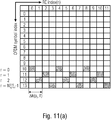
  • Fig. 11 illustrates examples of an RE allocation for a single SRS port p i .
  • Fig. 11 illustrates examples of an RE allocation for a single SRS port p i .
  • Fig. 11(a) illustrates an example of an RE allocation for
  • the SRS sequence is mapped to all REs within the SRS bandwidth over all N symb SRS symbols of the SRS resource, while
  • the SRS sequence is mapped to every second RE within the SRS bandwidth over all N symb SRS symbols of the SRS resource.
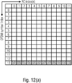
  • the SRS OFDM symbols associated with the fully-staggered or partly-staggered SRS resource pattern may be combined or de-staggered to a single SRS OFDM symbol in the frequency domain, as is illustrated in Fig. 12 .
  • Fig. 12(a) illustrates the equivalent de-staggered resource pattern for the example of Fig. 11(a) .
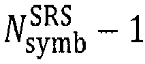
  • the SRS sequence is mapped to al REs within the SRS bandwidth over symbol N symb SRS ⁇ 1 of the SRS resource, which is the OFDM symbol having the index 13 in Fig. 12(a) .
  • the de-staggered single SRS OFDM symbol has a comb-1 like resource pattern.
  • Fig. 12(b) illustrates the equivalent de-staggered resource pattern for the example of Fig. 11(b) .
  • the SRS sequence is mapped to every second RE within the SRS bandwidth over symbol N symb SRS ⁇ 1 of the SRS resource, which is the OFDM symbol having the index 13 in Fig. 12(b) .
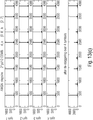
  • Fig. 13 illustrates the behavior of the cross-correlation for conventional configurations in line with TS38.211, Rel. 15 including, in addition to TS38.211, Rel. 15, an extended parameter range.
  • FIG. 13(a) shows the cross correlation of the OFDM symbol with a reference signal.
  • the second to fourth subplots sym2 to sym4 show no cross correlation as only one symbol, sym1, is used.
  • the last subplot shows the de-staggered signal.
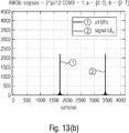
  • Fig. 13(b) is an enlarged view of the last subplot of Fig. 13(a) , illustrating the correlation of the input signal with the reference sequence.
  • the input signal is the sum of the signals from two UEs sharing the same REs, and the reference sequence is the base sequence, i.e., the sequence without cyclic shift.
  • the first subplot sym1 in Fig. 13(c) shows the cross correlation of the OFDM symbol with a reference signal.
  • the second to fourth subplots sym2 to sym4 show the cross correlation.
  • the last subplot shows the de-staggered signal.
  • Fig. 13(d) is an enlarged view of the last subplot of Fig. 13(d) , illustrating the correlation of the input signal with the reference sequence.
  • the input signal is the sum of the signals from two UEs sharing the same REs, and the reference sequence used for the cross correlation is the base sequence, i.e., the sequence without cyclic shift.
  • Fig. 13(b) and Fig. 13(d) it may be overserved that the correlation function of the de-staggered signal is different from the signal with comb-1 which exhibits aliasing peaks.
  • the cross-correlation function of the de-staggered signal includes many additional peaks when compared to the signal with comb-1.
  • the first arriving path, FAP is selected for ToA measurements for positioning applications.
  • the aliasing peaks lead to an ambiguity in the detection of the FAP which limits the available search space of the correlation peaks.
  • the aliasing peaks arise due to phase discontinuity over the RE index of the de-staggered SRS resource pattern.
  • the de-staggered SRS does not have the same linear phase behavior than a non-de-staggered SRS.
  • the inventive approach addresses this issue and provides several embodiments to correct the phase behavior of the SRS OFDM symbols of the SRS resource when the UE is configured with a staggered SRS resource pattern.
  • the UE when the resource mapping of the configured SRS resource is a staggered SRS resource mapping, the UE applies a valued correction factor per SRS OFDM symbol, e.g., a complex valued correction factor.
  • the aim of the correction factor is to eliminate the alias peaks of the correction function caused by the phase discontinuity between the different SRS OFDM symbols of the staggered SRS resource pattern.
  • the correction factor may be applied either in time or frequency domain to each SRS OFDM symbol and depends on the relative comb offset value, RE offset, ⁇ k ( p i ,l ') of the l '-th SRS OFDM symbol, the comb value K TC of the SRS resource mapping pattern and the cyclic shift ⁇ of the SRS sequence.
  • the correction factor is independent of the SRS sequence RE index " n ", i.e., is the same or identical for each RE or for each column in Fig. 11 or Fig. 12 .
  • the effective value range of the cyclic shifts may be increased without modifying the value range of the cyclic shifts used in the generation of the SRS sequence.
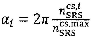
  • the parameter n SRS cs , i denotes the configured cyclic shift value.
  • the cyclic shifts of the SRS sequence may be configured to the UE.
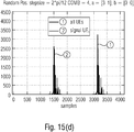
  • Fig. 15 illustrates the results of applying a correction factor according to the above to the OFDM symbol.
  • Fig. 15(a) illustrates in the first to fourth subplot, like Fig. 13(c) , the cross correlation of the OFDM symbols with a reference signal.
  • the last subplot in Fig. 15(a) shows the de-staggered signal, and is illustrated enlarged in Fig. 15(b) .
  • Fig. 15(b) When comparing Fig. 15(b) and Fig. 13(c) one may see the effect of applying the correction factor, namely the substantial reduction of the peaks in the cross-correlation.
  • Fig. 15(c) and Fig. 15(d) are similar to Fig. 15(a) and Fig. 15(b) , except that a multipath propagation of the input signals from the different UEs is assumed. Also, in case of a multipath propagation, applying the correction factor allows for a substantial reduction of the peaks in the cross-correlation.
  • the UEs are separated using cyclic shifts.
  • the present invention is not limited to UE being separated using cyclic shifts, and in accordance with other embodiments, instead of using cyclic shifts, the UEs are separated by a different aliasing selection index.
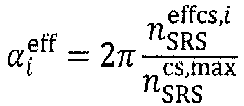
  • the effective range for the allowed ToA difference may be extended by including an alias selection index ⁇ i in the calculation of the correction factor, and, in accordance with embodiments, the correction factor may be split into two parts:
  • ⁇ i [0 .. K TC [ is an integer value.
  • K TC - 1 ⁇ is a configured integer value
  • ⁇ k ⁇ k ( l ') relative comb offset value of the l '-th SRS OFDM symbol
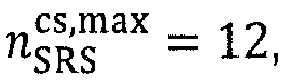
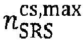
  • n SRS cs max number of configured cyclic shifts used for the calculation of ⁇ i .
  • the parameters n SRS cs ⁇ 0 , ... , n SRS cs , max ⁇ 1 and ⁇ are configured to the apparatus (instead of the parameter n SRS effcs ) via a higher layer, e.g., using RRC signaling, or via a lower layer (physical layer).
  • ⁇ 1 ⁇ i ⁇ k K TC ⁇ i ⁇ k K TC
  • ⁇ 2 ⁇ k K TC a i 2 ⁇ ⁇ k K TC a
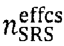
  • the parameter n SRS effcs ⁇ 0 , ... , K TC n SRS cs , max ⁇ 1 is configured to the apparatus via a higher layer, e.g., using RRC signaling, or via a lower layer (physical layer).
  • the cyclic shift value/index n SRS effcs may be configured to the apparatus by a network identity, e.g., a base station (gNB).
  • a network identity e.g., a base station (gNB).
  • the correction factor e j ⁇ ( ⁇ i , ⁇ k,K TC ) or e j ⁇ ⁇ i eff ⁇ k is increased without modifying the SRS sequence generation.
  • An extension of the value range of the cyclic shift value/index n SRS effcs requires a change of the Rel. 15 higher layer SRS resource set or SRS resource configuration. In some cases, such a change may not be possible or wanted, and the value range of the effective cyclic shifts used in the calculation of the phase offset correction factor may be limited.
  • FIG. 16 illustrates the results of applying the correction factor to the OFDM symbol in case the UEs are separated by different aliasing selection indices only, as indicated by the parameter "a" in Fig. 16 .
  • Fig. 16(a) illustrates in the first to fourth subplot the cross correlation of the OFDM symbols with a reference signal. The last subplot in Fig. 16(a) shows the de-staggered signal, and is illustrated enlarged in Fig. 16(b) .
  • applying the correction factor causes a substantial reduction of the peaks in the cross-correlation.
  • the above described parameters effective/virtual n SRS effcs , i or a i may configured to the UE via higher layer signaling, like RRC signaling, or via physical layer signaling or derived from other parameter.
  • the UE may be configured with the cyclic shift value n SRS cs , i or ⁇ i used for the calculation of the cyclic shifted base sequence.
  • n SRS cs , i may be derived from the parameter n SRS cs common to all antenna ports ant the antenna port index. This allows for the following options
  • the correction factor may be either applied after the SRS OFDM symbol generation, or during the SRS OFDM symbol generation. In the following two embodiments for applying the correction factor during the SRS OFDM symbol generation are described.
  • Fig. 17 illustrates an embodiment of an UL positioning procedure for determining the position of a UE using an SRS modified in accordance with the inventive approach. It is assumed that the target UE has an established connection with the s-gNB.
  • the location management function, LMF is connected of the Reception Points, RPs via the NR Positioning Protocol A, NRPPa, or via another interface and is aware of the RPs capabilities.
  • the LMF received a positioning request from a location client to locate the target UE.
  • the positioning method demands the UE to transmit a UL-PRS, e.g., ULTDOA, or eCID. Multiple SRS resources sharing the time and frequency and allocated to the target UE are used.
  • the LMF forwards 400 a request to configure an SRS resource to the s-gNB serving the target UE.
  • the resource configuration may be based on information available at the network, and may include a coarse UE position, a number of UEs sharing the same frequency time resources, and the UE behavior.
  • the LMF may suggest an SRS resource setting to the s-gNB, and request the UE antenna capabilities from the gNB, e.g., over the NRPPa interface, or directly from the UE over the LTE positioning protocol, LPP, interface.
  • the s-gNB is the coordination unit, the s-gNB requests the SRS resources within the positioning area either directly from the n-gNBs or from the LMF.
  • the s-gNB sets 402 the resource setting and configures 404 the target UE with the SRS transmission configuration.
  • the s-gNB provides 404 the LMF with the configured SRS resources.
  • the LMF provides 406 the RPs ,over the NRPPa interface, with the SRS configuration, which are needed to detect the signal.
  • the LMF provides 408 the RPs with the report setting for a given SRS resource or resource set.
  • the report setting may assist the LMF or, more generally, the coordinating node, to identify whether the resources allocated with different cyclic shifts cause an interference with other SRS resources, e.g., resources dedicated to other UEs or from different antenna ports of the same UE.
  • the report setting may either include the Channel Impulse Response reporting setting, or may indicate the RPs to report the information related to interference caused from a non-ideal resource allocation.
  • the RP computes 410 the TOA measurements, generates 412 the report according to the report setting received at 408, and forwards 414 the information to the LMF.
  • the SRS resource may be a single measurement, a periodic measurement or a semi-persistent measurement.
  • the LMF computes 416 the UE position from the TOA report.
  • the wireless communication system may include a terrestrial network, or a non-terrestrial network, or networks or segments of networks using as a receiver an airborne vehicle or a spaceborne vehicle, or a combination thereof.
  • the user device, UE may be one or more of a mobile terminal, or a stationary terminal, or a cellular loT-UE, or a vehicular UE, or a vehicular group leader (GL) UE, or an IoT, or a narrowband IoT, NB-IoT, device, or a WiFi non Access Point STAtion, non-AP STA, e.g., 802.11 ax or 802.11 be, or a ground based vehicle, or an aerial vehicle, or a drone, or a moving base station, or a road side unit, or a building, or any other item or device provided with network connectivity enabling the item/device to communicate using the wireless communication network, e.g., a sensor or actuator, or any other item or device provided with network connectivity enabling the item/device to communicate using a sidelink the wireless communication network, e.g., a sensor or actuator, or any sidelink capable network entity.
  • a sidelink the wireless communication network e.g., a
  • the base station, BS may be implemented as mobile or immobile base station and may be one or more of a macro cell base station, or a small cell base station, or a central unit of a base station, or a distributed unit of a base station, or a road side unit, or a UE, or a group leader (GL), or a relay, or a remote radio head, or an AMF, or an SMF, or a core network entity, or mobile edge computing entity, or a network slice as in the NR or 5G core context, or a WiFi AP STA, e.g., 802.11 ax or 802.11 be, or any transmission/reception point, TRP, enabling an item or a device to communicate using the wireless communication network, the item or device being provided with network connectivity to communicate using the wireless communication network.
  • a WiFi AP STA e.g., 802.11 ax or 802.11 be, or any transmission/reception point, TRP, enabling an item or a device to communicate using the wireless
  • aspects of the described concept have been described in the context of an apparatus, it is clear that these aspects also represent a description of the corresponding method, where a block or a device corresponds to a method step or a feature of a method step. Analogously, aspects described in the context of a method step also represent a description of a corresponding block or item or feature of a corresponding apparatus.
  • Various elements and features of the present invention may be implemented in hardware using analog and/or digital circuits, in software, through the execution of instructions by one or more general purpose or special-purpose processors, or as a combination of hardware and software.
  • embodiments of the present invention may be implemented in the environment of a computer system or another processing system.
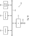
  • Fig. 18 illustrates an example of a computer system 500.
  • the units or modules as well as the steps of the methods performed by these units may execute on one or more computer systems 500.
  • the computer system 500 includes one or more processors 502, like a special purpose or a general-purpose digital signal processor.
  • the processor 502 is connected to a communication infrastructure 504, like a bus or a network.
  • the computer system 500 includes a main memory 506, e.g., a random-access memory (RAM), and a secondary memory 508, e.g., a hard disk drive and/or a removable storage drive.
  • the secondary memory 508 may allow computer programs or other instructions to be loaded into the computer system 500.
  • the computer system 500 may further include a communications interface 510 to allow software and data to be transferred between computer system 500 and external devices.
  • the communication may be in the from electronic, electromagnetic, optical, or other signals capable of being handled by a communications interface.
  • the communication may use a wire or a cable, fiber optics, a phone line, a cellular phone link, an RF link and other communications channels 512.
  • computer program medium and “computer readable medium” are used to generally refer to tangible storage media such as removable storage units or a hard disk installed in a hard disk drive.
  • These computer program products are means for providing software to the computer system 500.
  • the computer programs also referred to as computer control logic, are stored in main memory 506 and/or secondary memory 508. Computer programs may also be received via the communications interface 510.
  • the computer program when executed, enables the computer system 500 to implement the present invention.
  • the computer program when executed, enables processor 502 to implement the processes of the present invention, such as any of the methods described herein. Accordingly, such a computer program may represent a controller of the computer system 500.
  • the software may be stored in a computer program product and loaded into computer system 500 using a removable storage drive, an interface, like communications interface 510.
  • the implementation in hardware or in software may be performed using a digital storage medium, for example cloud storage, a floppy disk, a DVD, a Blue-Ray, a CD, a ROM, a PROM, an EPROM, an EEPROM or a FLASH memory, having electronically readable control signals stored thereon, which cooperate (or are capable of cooperating) with a programmable computer system such that the respective method is performed. Therefore, the digital storage medium may be computer readable.
  • a digital storage medium for example cloud storage, a floppy disk, a DVD, a Blue-Ray, a CD, a ROM, a PROM, an EPROM, an EEPROM or a FLASH memory, having electronically readable control signals stored thereon, which cooperate (or are capable of cooperating) with a programmable computer system such that the respective method is performed. Therefore, the digital storage medium may be computer readable.
  • Some embodiments according to the invention comprise a data carrier having electronically readable control signals, which are capable of cooperating with a programmable computer system, such that one of the methods described herein is performed.
  • embodiments of the present invention may be implemented as a computer program product with a program code, the program code being operative for performing one of the methods when the computer program product runs on a computer.
  • the program code may for example be stored on a machine readable carrier.
  • inventions comprise the computer program for performing one of the methods described herein, stored on a machine readable carrier.
  • an embodiment of the inventive method is, therefore, a computer program having a program code for performing one of the methods described herein, when the computer program runs on a computer.
  • a further embodiment of the inventive methods is, therefore, a data carrier (or a digital storage medium, or a computer-readable medium) comprising, recorded thereon, the computer program for performing one of the methods described herein.
  • a further embodiment of the inventive method is, therefore, a data stream or a sequence of signals representing the computer program for performing one of the methods described herein. The data stream or the sequence of signals may for example be configured to be transferred via a data communication connection, for example via the Internet.
  • a further embodiment comprises a processing means, for example a computer, or a programmable logic device, configured to or adapted to perform one of the methods described herein.
  • a further embodiment comprises a computer having installed thereon the computer program for performing one of the methods described herein.
  • a programmable logic device for example a field programmable gate array
  • a field programmable gate array may cooperate with a microprocessor in order to perform one of the methods described herein.
  • the methods are preferably performed by any hardware apparatus.

Landscapes

  • Engineering & Computer Science (AREA)
  • Computer Networks & Wireless Communication (AREA)
  • Signal Processing (AREA)
  • Physics & Mathematics (AREA)
  • General Physics & Mathematics (AREA)
  • Radar, Positioning & Navigation (AREA)
  • Remote Sensing (AREA)
  • Mobile Radio Communication Systems (AREA)

Abstract

An apparatus for a wireless communication system is described. The apparatus is to transmit a reference signal on a common set of resource elements, REs, the common set of REs used by one or more further apparatuses in the wireless communication system to transmit the reference signal so that the reference signals of the apparatus and of the one or more further apparatuses use the same REs. The apparatus is to transmit the reference signal using a plurality of OFDM symbols, each OFDM symbol having a comb structure, and some or all of the OFDM symbols having different comb offsets, and apply the same sequence to each OFDM symbol, the sequence having a zero auto correlation property, the apparatus and the one or more further apparatus using for a common RE the same sequence. The apparatus is to apply a phase correction to an OFDM symbol before transmission, wherein the phase correction is applied in the time domain or in the frequency domain by multiplying the ODFM symbol with a correction factor ejϕc , and wherein the correction factor ejϕc depends on the comb factor and the comb offset of the OFDM symbol and is independent of the resource element.

Description

  • The present application relates to the field of wireless communication systems or networks, more specifically to enhancements or improvements regarding reference signals to be employed in the wireless communication system or network for various purposes. Embodiments of the present invention concern approaches for an ambiguity/aliasing reduction or cancellation for staggered reference signals, like positioning reference signals used for determining positions of one or more entities in the wireless communication system or network.
  • Fig. 1 is a schematic representation of an example of a terrestrial wireless network 100 including, as is shown in Fig. 1(a), a core network 102 and one or more radio access networks RAN1, RAN2, ...RANN. Fig. 1(b) is a schematic representation of an example of a radio access network RANn that may include one or more base stations gNB1 to gNB5, each serving a specific area surrounding the base station schematically represented by respective cells 1061 to 1065. The base stations are provided to serve users within a cell. The one or more base stations may serve users in licensed and/or unlicensed bands. The term base station, BS, refers to a gNB in 5G networks, an eNB in UMTS/LTE/LTE-A/ LTE-A Pro, or just a BS in other mobile communication standards. A user may be a stationary device or a mobile device. The wireless communication system may also be accessed by mobile or stationary loT devices which connect to a base station or to a user. The mobile devices or the loT devices may include physical devices, ground based vehicles, such as robots or cars, aerial vehicles, such as manned or unmanned aerial vehicles (UAVs), the latter also referred to as drones, buildings and other items or devices having embedded therein electronics, software, sensors, actuators, or the like as well as network connectivity that enables these devices to collect and exchange data across an existing network infrastructure. Fig. 1(b) shows an exemplary view of five cells, however, the RANn may include more or less such cells, and RANn may also include only one base station. Fig. 1(b) shows two users UE1 and UE2, also referred to as user equipment, UE, that are in cell 1062 and that are served by base station gNB2. Another user UE3 is shown in cell 1064 which is served by base station gNB4. The arrows 1081, 1082 and 1083 schematically represent uplink/downlink connections for transmitting data from a user UE1, UE2 and UE3 to the base stations gNB2, gNB4 or for transmitting data from the base stations gNB2, gNB4 to the users UE1, UE2, UE3. This may be realized on licensed bands or on unlicensed bands. Further, Fig. 1(b) shows two loT devices 1101 and 1102 in cell 1064, which may be stationary or mobile devices. The loT device 1101 accesses the wireless communication system via the base station gNB4 to receive and transmit data as schematically represented by arrow 1121. The loT device 1102 accesses the wireless communication system via the user UE3 as is schematically represented by arrow 1122. The respective base station gNB1 to gNB5 may be connected to the core network 102, e.g. via the S1 interface, via respective backhaul links 1141 to 1145, which are schematically represented in Fig. 1(b) by the arrows pointing to "core". The core network 102 may be connected to one or more external networks. Further, some or all of the respective base station gNB1 to gNB5 may be connected, e.g. via the S1 or X2 interface or the XN interface in NR, with each other via respective backhaul links 1161 to 1165, which are schematically represented in Fig. 1(b) by the arrows pointing to "gNBs". A sidelink channel allows direct communication between UEs, also referred to as device-to-device (D2D) communication. The sidelink interface in 3GPP is named PC5.
  • For data transmission a physical resource grid may be used. The physical resource grid may comprise a set of resource elements to which various physical channels and physical signals are mapped. For example, the physical channels may include the physical downlink, uplink and sidelink shared channels (PDSCH, PUSCH, PSSCH) carrying user specific data, also referred to as downlink, uplink and sidelink payload data, the physical broadcast channel (PBCH) carrying for example a master information block (MIB) and one or more of a system information block (SIB), the physical downlink, uplink and sidelink control channels (PDCCH, PUCCH, PSSCH) carrying for example the downlink control information (DCI), the uplink control information (UCI) and the sidelink control information (SCI). Note, the sidelink interface may a support 2-stage SCI. This refers to a first control region containing some parts of the SCI, and optionally, a second control region, which contains a second part of control information.
  • For the uplink, the physical channels may further include the physical random access channel (PRACH or RACH) used by UEs for accessing the network once a UE synchronized and obtained the MIB and SIB. The physical signals may comprise reference signals or symbols (RS), synchronization signals and the like. The resource grid may comprise a frame or radio frame having a certain duration in the time domain and having a given bandwidth in the frequency domain. The frame may have a certain number of subframes of a predefined length, e.g. 1ms. Each subframe may include one or more slots of 12 or 14 OFDM symbols depending on the cyclic prefix (CP) length. A frame may also consist of a smaller number of OFDM symbols, e.g. when utilizing shortened transmission time intervals (sTTI) or a mini-slot/non-slot-based frame structure comprising just a few OFDM symbols.
  • The wireless communication system may be any single-tone or multicarrier system using frequency-division multiplexing, like the orthogonal frequency-division multiplexing (OFDM) system, the orthogonal frequency-division multiple access (OFDMA) system, or any other IFFT-based signal with or without CP, e.g. DFT-s-OFDM. Other waveforms, like non-orthogonal waveforms for multiple access, e.g. filter-bank multicarrier (FBMC), generalized frequency division multiplexing (GFDM) or universal filtered multi carrier (UFMC), may be used. The wireless communication system may operate, e.g., in accordance with the LTE-Advanced pro standard, or the 5G or NR, New Radio, standard, or the NR-U, New Radio Unlicensed, standard.
  • The wireless network or communication system depicted in Fig. 1 may be a heterogeneous network having distinct overlaid networks, e.g., a network of macro cells with each macro cell including a macro base station, like base station gNB1 to gNB5, and a network of small cell base stations (not shown in Fig. 1), like femto or pico base stations.
  • In addition to the above described terrestrial wireless network also non-terrestrial wireless communication networks (NTN) exist including spaceborne transceivers, like satellites, and/or airborne transceivers, like unmanned aircraft systems. The non-terrestrial wireless communication network or system may operate in a similar way as the terrestrial system described above with reference to Fig. 1, for example in accordance with the LTE-Advanced Pro standard or the 5G or NR, new radio, standard.
  • In a wireless communication system, like the one described above with reference to Fig. 1, various reference signals may be used, e.g., downlink reference signals, uplink reference signals, synchronization signals or positioning reference signals, PRS. The downlink reference signals may have a two-dimensional reference-signal sequence, which indicates the cell identity. The uplink reference signals may include demodulation reference signals, DM-RS, and sounding reference signals, SRSs. The synchronization signals may include the primary synchronization sequence, PSS, and the secondary synchronization sequence, SSS. The positioning reference signal may be used to determine the location of an entity based on radio access network information.
  • It is noted that the information in the above section is only for enhancing the understanding of the background of the invention and therefore it may contain information that does not form prior art that is already known to a person of ordinary skill in the art.
  • Starting from the prior art as described above, there may be a need for enhancements or improvements for providing or transmitting reference signals in a wireless communication system.
  • Embodiments of the present invention are now described in further detail with reference to the accompanying drawings:
  • Fig. 1
    shows a schematic representation of an example of a wireless communication system;
    Fig. 2
    illustrates a scenario for positioning applications;
    Fig. 3
    schematically illustrate the timing or temporal behavior of SRS signals used in the positioning scenario of Fig. 2;
    Fig. 4
    illustrates a scenario in which three UEs send in the same time slot;
    Fig. 5
    illustrates an effective correlation peak without cyclic shift (Fig. 5(a)) and with cyclic shift (Fig. 5(b));
    Fig. 6
    illustrates an allocation of REs for the transmission of an SRS with four OFDM symbols and a transmission COMB factor of 4;
    Fig. 7
    illustrates the principle of staggering/de-staggering;
    Fig. 8
    illustrates the increase in correlation peaks when applying a transmission comb;
    Fig. 9
    illustrates a limited distance, maxToaDifference, in the spectrum of Fig. 8(b);
    Fig. 10
    is a schematic representation of a wireless communication system including a transmitter, like a base station, and one or more receivers, like user devices, UEs for implementing embodiments of the present invention;
    Fig. 11
    illustrates examples of an RE allocation for a single SRS port;
    Fig. 12
    illustrates the combining or de-staggering of SRS OFDM symbols associated with a fully-staggered or partly-staggered SRS resource pattern to a single SRS OFDM symbol in the frequency domain;
    Fig. 13
    illustrates the behavior of the cross-correlation for conventional configurations;
    Fig. 14
    illustrates a phase over the RE index of a de-staggered comb-1 SRS;
    Fig. 15
    illustrates the results of applying the correction factor in accordance with embodiments of the present invention to an OFDM symbol;
    Fig. 16
    illustrates the results of applying the correction factor to the OFDM symbol in case the UEs are separated by different aliasing selection indices only;
    Fig. 17
    illustrates an embodiment of an UL positioning procedure for determining the position of a UE using an SRS modified in accordance with embodiments of the inventive approach; and
    Fig. 18
    illustrates an example of a computer system on which units or modules as well as the steps of the methods described in accordance with embodiments of the inventive approach may execute.
  • Embodiments of the present invention are now described in more detail with reference to the accompanying drawings in which the same or similar elements have the same reference signs assigned.
  • As mentioned above, in wireless communication systems or networks, like those described above with reference to Fig. 1, the respective entities may employ reference signals for various purposes. In the following, the use of such reference signals by the respective entities is described with reference to a positioning application for identifying positions of multiple UEs employing SRS transmissions. However, the present invention is not limited to such implementations. Embodiments of the present invention are applicable to any reference signal employed in the wireless communication signal, e.g., reference signals used in the UL or in the DL or in the sidelink, SL.
  • Fig. 2 illustrates a scenario for positioning applications. Fig. 2 may be a part or a wireless communication system or network as described above with reference to Fig. 1, like a 4G or 5G network, and shows four UE, UE1 to UE4, as well as four serving base stations, s-gNB1 to s-gNB4, serving the respective UEs. As is indicated by the double-headed arrows in Fig. 2 each of the UEs is synchronized to its s-gNB. In the UE a time at which a transmission is made is adjusted by the timing advance, TA, so that signals from different UEs being derived by the s-gNB arrive at the s-gNB aligned with each other, i.e., aligned to the framing of the s-gNB. Typically, a UE is logged in at or is served by the s-gNB to which the UE has the shortest distance. The TA is adjusted according to the distance between the UE and the s-gNB. For positioning applications multiple s-gNBs need to receive a signal, like an SRS signal, from a respective UE, as indicated by the single-headed arrows in Fig. 2, so that, according to the respective distances of a UE to the s-gNBs, the signals arrive at different times. From this difference in time of arrival, TOA, the position of the transmitter, the UE, may be determined.
  • Fig. 3 schematically illustrate the timing or temporal behavior of such SRS signals in case there are one transmitter and three receivers. For positioning applications, the s-gNBs are synchronized, i.e., the framing of the s-gNBs is synchronized and the signal processing is synchronized to this framing. For example, the OFDM symbol timing is synchronized. Initially, a transmitter is considered and the ToA is indicated for different receivers, like ToA1 ... ToA3 in Fig. 3. In order to minimize the number of time slots required for the positioning signals, it is desirable for multiple UEs to use the same resources, i.e. to occupy the same REs. For the localization or positioning technique according to the Time Difference of Arrival, TDOA, principle, the transmission time needs to be known. An exact synchronization of the transmission time, the Time-of-Transmit, ToT, is therefore not necessary. An OFDM demodulator usually uses only the payload symbol. The so-called cyclic prefix is removed before further processing. For localization or positioning applications, an exact synchronization is not necessary. A non-ideal synchronization of the symbol timing of the demodulator usually means only a slight reduction of the SINR. Since a low SINR is sufficient anyway for the ToA determination, an exact synchronization of the demodulator may therefore be dispensed with. A coarse synchronization according to the principles of TA is sufficient. This results in a temporal behavior for the receiver as illustrated in Fig. 4. Fig. 4 illustrates a scenario in which three UEs send to one receiver in the same time slot. According to the TA settings and the distance the signals arrive with a time delay at a receiver. The time difference is relatively small compared to the OFDM symbol duration. The relevant signal part for further processing signals indicated by the OFDM symbol window. Besides the advantage of the multiple use of an REs, this results in another advantage: The signals maybe processed substantially in parallel by an OFDM demodulator and are only separated after the OFDM demodulation.
  • To separate the signals, the following concepts may be employed:
    • Code multiplex: each UE uses a different sequence, or
    • Cyclic Shift: the sequences used by the UEs are cyclically shifted by a fraction of the length of the OFDM symbol; this results in temporal offset correlation peaks, which may then each be assigned to a UE.
  • Fig. 5 illustrates an effective correlation peak without cyclic shift (Fig. 5(a)) and with cyclic shift (Fig. 5(b)).
  • When considering, for example, the following parameters of the 4G/5G standards, the following may be observed:
    - sub-carrier-spacing 30kHz
    - duration of an OFDM-Symbols incl. CP: 0.5ms/14 = 35.7 µs
    - without CP: 33.3µs
    - 6 UEs → 6 different cyclic shifts cs = n*5.5µs with n = 0...5
    - this corresponds to a distance of 1.66km
    - with an FFT-length of 2048 this corresponds to n*341.333 samples
  • Thus, in the above example, the correlation peaks may be uniquely allocated if the distance differences are smaller than 1.6km. That may be enough for many applications, and for a non-ideal TA the value may be reduced accordingly. For larger cyclic shift steps, i.e., fewer UEs are multiplexed, the range of values increases.
  • For standards like 4G/5G the resource elements, REs, in the time-frequency may be allocated to different UEs for SRS transmission. The channel impulse response of the full assigned bandwidth may be obtained if all subcarriers within the assigned bandwidth are used. Alternatively, the bandwidth may be sounded (CIR sampled, CIR=Channel Interference Ratio) using a transmission comb structure and using a different offset in different OFDM symbols. One way to sample the CIR is to use a transmission comb structure with repetition as shown in Fig. 6. Fig. 6 illustrates the allocation of REs for the transmission of the SRS with four OFDM symbols sym1, sym2, sym3, sym4 and a transmission COMB factor of 4, i.e., every fourth subcarrier is used for the SRS transmission. Assuming the same power for each OFDM symbol the overall energy used for the SRS transmission is increased if the number of symbols in increase (Fig. 6), thereby enlarging the coverage range of SRS transmissions.
  • Another approach is to assign different offsets to the transmission in subsequent OFDM symbols with respect to the first one. This is illustrated in Fig. 7 illustrating the principle of staggering/de-staggering. Fig. 7(a) illustrates the allocation of the REs for the transmission of SRS with one OFDM symbol sym1. Fig. 7(b) illustrates the staggering of the SRS REs of Fig. 7(a) in the time and frequency domains, and Fig. 7(c) illustrates the de-staggering of the SRS REs of Fig. 7(b). As is illustrated, the REs for the transmission of the SRS are distributed over the four OFDM symbols sym1, sym2, sym3, sym4 with a transmission COMB factor of 4 in each symbol. Further, different offsets are assigned to the transmissions in subsequent OFDM symbols with respect to the first symbol sym1. The offset for the REs in the second symbol sym2 is one RE with respect to the first symbol sym1, the offset for the REs in the third symbol sym3 is two REs with respect to the first symbol sym1, and the offset for the REs in the fourth symbol sym4 is three REs with respect to the first symbol sym1.
  • The available transmit power is one of the limiting factors in reaching multiple TRPs and using the transmission comb is an efficient method to concentrate the available transmit power on the reduced number of subcarriers, while maintaining the overall bandwidth. The former achieves the goal of power boosting and the latter maintains the time resolution.
  • However, the downside of using the transmission comb is that the aliases of correlation peaks occur. The de-staggered reference signals include an ambiguity/aliasing because the correlation peaks repeat at a distance given by NFFT/KTC, where NFFT is the size of the FFT and KTC is the COMB factor. This ambiguity/aliasing limits the separating of multiple users efficiently.
  • However, the downside of using transmission comb is that the aliases of correlation peaks occur. The correlation peaks repeat at a distance given by NFFT/KTC, where NFFT is the size of FFT and KTC is the comb factor. This provides a basic limitation in separating multiple users efficiently.
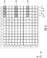
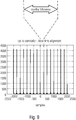
  • For example, when applying the transmission comb together with the cyclic-shifts, this results combcs_values correlation peaks. Thus, when considering a transmission comb with comb = 4 and 4 cs values, instead of the peaks illustrated in Fig. 8(a), there will be 16 correlation peaks as illustrated in Fig. 8(b). When considering the above example and a comb = 8, the correlation peaks may be uniquely allocated if the distance differences allowing to uniquely separate correlation peaks may drop from 1.6km to 200m, equivalent to 42 samples at a FFT-length = 2048 and a SCS = 30kHz. Fig. 9 illustrates this limited distance, the maxToaDifference, in the spectrum of Fig. 8(b). When using multiple symbols and staggering, an effective comb value is achieved, with combEff = comb/nbSym, nbSym = number of symbols.
  • On approach partly addressing the issue of above discussed ambiguity/aliasing is described in TDOC R1-1911229 and suggests to generate a modified sequence for each OFDM symbol so as to ensure phase continuity is ensured. In other words, rather than using a common base sequence, different base sequences are to be used for each symbol. However, this requires generating a specific sequence for each symbol increasing the processing overhead and, thereby also the power consumption, and, since the number of sequences that is actually supported remains the same, i.e., is not increased, the flexibility is low.
  • To improve the separation of multiple users efficiently, the ambiguity/aliasing needs to be resolved.
  • The present invention provides improvements and enhancements in a wireless communication system or network addressing the above described issue, while avoiding the drawbacks of conventional approaches addressing this issue. The present invention provides approaches for reducing or canceling an ambiguity/aliasing of staggered reference signals after de-staggering them, like positioning reference signals used for determining positions of multiple entities in the wireless communication system or network.
  • Embodiments of the present invention concern approaches allowing use for the propagation or distance difference the entire range as defined by combEff = comb/nbSym. This is achieved by combining the correlations of multiple OFDM-symbols to obtain the combined channel impulse response, with a phase correction applied to each ODM symbol. In accordance with embodiments of the inventive approach the phase offset correction is applied to OFDM symbols belonging to the same SRS resource so that the symbols may be coherently added, thereby reducing or canceling the ambiguity/aliasing of staggered reference signals after de-staggering them. The inventive approach provides the following improvements:
    • a constructive addition of the correlations of the one resource set is ensured,
    • the ambiguity reduction/cancellation increases the allowed range of the ToA difference,
    • a small step size allows to multiplex many UE to one set of resource elements,
    • several antenna ports of one UE or gNB may be activated with the signals distinguished only by a small cyclic shift.
  • The inventive approach is advantageous as it supports a higher effective delay range of the cyclic shift, allows a small step size and minimizes the required modification to Rel. 15. Embodiments of the inventive approach allow the distribution of the REs assigned to one UE or gNB to several symbols, and improves the cross-correlation properties of the received signal thereby allowing for a better separation of the signals transmitted from different UEs or gNBs. With better cross-correlation properties more UEs or gNBs may share the same REs.
  • Embodiments of the present invention may be implemented in a wireless communication system as depicted in Fig. 1 including base stations and users, like mobile terminals or loT devices. Fig. 10 is a schematic representation of a wireless communication system including a transmitter 300, like a base station, and one or more receivers 302, 304, like user devices, UEs. The transmitter 300 and the receivers 302, 304 may communicate via one or more wireless communication links or channels 306a, 306b, 308, like a radio link. The transmitter 300 may include one or more antennas ANTT or an antenna array having a plurality of antenna elements, a signal processor 300a and a transceiver 300b, coupled with each other. The receivers 302, 304 include one or more antennas ANTUE or an antenna array having a plurality of antennas, a signal processor 302a, 304a, and a transceiver 302b, 304b coupled with each other. The base station 300 and the UEs 302, 304 may communicate via respective first wireless communication links 306a and 306b, like a radio link using the Uu interface, while the UEs 302, 304 may communicate with each other via a second wireless communication link 308, like a radio link using the PC5/sidelink (SL) interface. When the UEs are not served by the base station, are not be connected to a base station, for example, they are not in an RRC connected state, or, more generally, when no SL resource allocation configuration or assistance is provided by a base station, the UEs may communicate with each other over the sidelink (SL). The system or network of Fig. 10, the one or more UEs 302, 304 of Fig. 10, and the base station 300 of Fig. 10 may operate in accordance with the inventive teachings described herein.
  • APPARATUS
  • The present invention provides (see for example claim 1) an apparatus for a wireless communication system, wherein
    the apparatus is to transmit a reference signal on a common set of resource elements, REs, the common set of REs used by one or more further apparatuses in the wireless communication system to transmit the reference signal so that the reference signals of the apparatus and of the one or more further apparatuses use the same REs,
    • wherein the apparatus is to
      • transmit the reference signal using a plurality of OFDM symbols, each OFDM symbol having a comb structure, and some or all of the OFDM symbols having different comb offsets, and
      • apply the same sequence to each OFDM symbol, the sequence having a zero auto correlation property, the apparatus and the one or more further apparatus using for a common RE the same sequence, and
    • wherein the apparatus is to apply a phase correction to an OFDM symbol before transmission, wherein the phase correction is applied in the time domain or in the frequency domain by multiplying the ODFM symbol with a correction factor e c , and wherein the correction factor ec depends on the comb factor and the comb offset of the OFDM symbol and is independent of the resource element.
  • In accordance with embodiments (see for example claim 2),
    • the sequence is a cyclic shifted base sequence,
    • the apparatus is to apply the same cyclic shifted basis sequence to each OFDM symbol, the cyclic-shifted base sequence having a zero auto correlation property,
    • wherein the correction factor ec depends on the comb factor, the comb offset of the OFDM symbol and the cyclic shift of the base sequence and is independent of the resource element.
  • In accordance with embodiments (see for example claim 3),
    • the sequence is a sequence with no cyclic shift, or the apparatus does not take into account the cyclic shift for the calculation of the correction factor,
    • the apparatus is to apply the same sequence to each OFDM symbol, the base sequence having a zero auto correlation property,
    • wherein the correction factor ec depends on the comb offset and comb factor of the OFDM symbol only.
  • In accordance with embodiments (see for example claim 4), the apparatus is to transmit the reference signal on a common set of REs used by one or more antenna ports of the apparatus to transmit the reference signal, and wherein for each antenna port a different cyclic shift may be used.
  • In accordance with embodiments (see for example claim 5), the resource or resource set of the reference signal is configured so that the apparatuses are distinguished by a first correction factor, and wherein the antenna ports of the apparatus are distinguished by second correction factor, the first correction factor implementing a coarser cyclic shift then the second correction factor.
  • In accordance with embodiments (see for example claim 6), the apparatus is configured with the cyclic shifts n SRS cs , i
    Figure imgb0001
    of the sequence, wherein n SRS cs , i
    Figure imgb0002
    is derived from a configuration parameter n SRS cs
    Figure imgb0003
    and wherein the range of n SRS cs , i
    Figure imgb0004
    may be extended as follows: n SRS cs , i = n SRS cs + n SRS cs , max p i 1000 N AP mod K TC n SRS cs , max ,
    Figure imgb0005
    or n SRS cs , i = n SRS cs K TC + n SRS cs , max p i 1000 N AP mod n SRS cs , max ,
    Figure imgb0006
    or n SRS cs , i = n SRS cs K TC + n SRS cs , max p i 1000 N AP mod K TC n SRS cs , max ,
    Figure imgb0007
    where
    n SRS cs
    Figure imgb0008
      configuration parameter,
    n SRS cs , i
    Figure imgb0009
      resulting parameter used to configure the cyclic shift for the antenna port i,
    n SRS cs , max
    Figure imgb0010
      maximum number of cyclic shifts,
    pi   antenna port identifier
    N AP  number of the antenna ports,
    K TC  transmission comb value.
  • In accordance with embodiments (see for example claim 7), the correction factor ec applied to the l'-th OFDM symbol is given by: e α i , Δk p i , K TC = e j φ 1 α i , Δk p i , K TC + φ 2 Δk p i , K TC , a i
    Figure imgb0011
    with φ 1 α i , Δk p i , K TC = α i Δk p i K TC ,
    Figure imgb0012
    and φ 2 Δk p i , K TC , a i = 2 π Δk p i K TC a i ,
    Figure imgb0013
    where
    • K TC transmission comb value
    • ai ∈ [0..K TC[ an integer value, e.g., received as configuration parameter or determined by other means)
    • Δk(pi ,l') relative comb offset value of the l'-th SRS OFDM for antenna port pi .
  • In accordance with embodiments (see for example claim 8), the correction factor ec applied to the l'-th OFDM symbol is given by: e α i , Δk p i , K TC = e i Δk p i K TC .
    Figure imgb0014
    where
  • KTC
    transmission comb value
    Δk(pi,l')
    relative comb offset value of the l'-th SRS OFDM for antenna port pi.
  • In accordance with embodiments (see for example claim 9), the correction factor ec applied to the l'-th OFDM symbol is given by: e α i , Δk p i , K TC = e i eff Δk p i K TC .
    Figure imgb0015
    with α i eff = 2 π n SRS effcs , i n SRS cs , max
    Figure imgb0016
    n SRS cs , i = n SRS effcs , i mod n SRS cs , max
    Figure imgb0017
    where
    K TC  transmission comb value,
    Δk(pi,l')  relative comb offset value of the l'-th SRS OFDM for antenna port pi ,
    n SRS cs , max
    Figure imgb0018
      maximum number of cyclic shifts,
    n SRS cs , i
    Figure imgb0019
      configured cyclic shift value,
    α i eff
    Figure imgb0020
      is calculated by α i eff = 2 π n SRS effcs , i n SRS cs , max
    Figure imgb0021
    with n SRS cs , i = n SRS effcs , i mod n SRS cs , max .
    Figure imgb0022

    n SRS effcs , i
    Figure imgb0023
      effective cyclic shift.
  • In accordance with embodiments (see for example claim 10), the apparatus is configured with n SRS effcs , i
    Figure imgb0024
    or ai via a higher layer, e.g., using RRC signaling, or via the physical layer.
  • In accordance with embodiments (see for example claim 11), the apparatus is to apply the correction factor ec after the OFDM symbol generation or during the OFDM symbol generation,
    wherein the apparatus is to apply the correction factor ec to the OFDM symbol r (pi )(k',l') during the mapping of the resource elements on the time-frequency grid for the antenna port pi as a K TC + k 0 p i , + l 0 p i = { 1 N AP β SRS e α i , Δk p i , K TC r p i = 0 , 1 , , M sc , b RS 1 = 0 , 1 , , N symb SRS 1 0 otherwise . ,
    Figure imgb0025
    where
    K TC  transmission comb value,
    k 0 p i
    Figure imgb0026
      frequency domain starting position for antenna port pi ,
    l 0  index of OFDM symbol within the slot containing where the SRS transmission starts,
    Δk(pi,l')  relative comb offset value of the l'-th SRS OFDM for antenna port pi,
    N AP  number of the antenna ports,
    β SRS  amplitude scaling factor to adjust transmit power,
    M sc , b RS
    Figure imgb0027
      the number of resource blocks used for transmitting SRS
    N symb SRS
    Figure imgb0028
      number of SRS symbols within a resource, or wherein the apparatus is to apply the correction factor ec to the sequence r( p i )(n,l') such that the phase-corrected OFDM symbol before mapping on the time frequency resources is given by r ˜ p i n = e α i , Δk p i , K TC r p i n , 0 n M sc , b RS 1 ,
    Figure imgb0029
    with r (pi )(n,l') = einr(pi) r u,v (n) being the cyclic shifted base sequence, l' = 0 , 1 , , N symb SRS 1 ,
    Figure imgb0030
    where
    K TC  transmission comb value,
    Δk(pi ,l')  relative comb offset value of the l'-th SRS OFDM for antenna port pi,
    M sc , b RS
    Figure imgb0031
      the number of resource blocks used for transmitting SRS,
    N symb SRS
    Figure imgb0032
      number of SRS symbols within a resource.
  • In accordance with embodiments (see for example claim 12), the sequence is a sounding reference signal, SRS, sequence or a positioning reference signal, PRS, sequence.
  • In accordance with embodiments, the apparatus comprises a user device, UE, the UE comprising one or more of: a mobile terminal, a stationary terminal, a cellular IoT-UE,, vehicular UE, vehicular group leader (GL) UE, an loT or narrowband loT, NB-IoT, device, a ground-based vehicle, an aerial vehicle, a drone, a moving base station, road side unit (RSU), a building, any other item or device provided with network connectivity enabling the item/device to communicate using the wireless communication network, e.g., a sensor or actuator, or any other item or device provided with network connectivity enabling the item/device to communicate using a sidelink the wireless communication network, e.g., a sensor or actuator, or any sidelink capable network entity.
  • In accordance with embodiments, the apparatus comprises a base station, BS, the BS comprising one or more of: a macro cell base station, a small cell base station, a central unit of a base station, a distributed unit of a base station, a road side unit (RSU), a UE, a group leader (GL), a relay, a remote radio head, an AMF, an SMF, a core network entity, mobile edge computing (MEC) entity, a network slice as in the NR or 5G core context, any transmission/reception point, TRP, enabling an item or a device to communicate using the wireless communication network, the item or device being provided with network connectivity to communicate using the wireless communication network.
  • REFERENCE SIGNAL
  • The present invention provides (see for example claim 13) a reference signal to be used in a wireless communication system, wherein
    • the reference signal is to be transmitted on a common set of resource elements, REs, the common set of REs used by a plurality of apparatuses in the wireless communication system to transmit the reference signals use the common set of REs,
    • the reference signal is to use a plurality of OFDM symbols, each OFDM symbol having a comb structure, and some or all of the OFDM symbol having different comb offsets,
    • the reference signal is obtained by applying the same sequence to each OFDM symbol, the base sequence having a zero auto correlation property, the apparatus and the one or more further apparatus using for a common RE the same sequence, and
    • the reference signal includes a phase correction applied in the time domain or in the frequency domain by multiplying the ODFM symbol with a correction factor e c , and wherein the correction factor ec depends on the comb factor and the comb offset of the OFDM symbol and is independent of the resource element.
    SYSTEM
  • The present invention provides (see for example claim 14) a wireless communication system, the wireless communication system comprising one or more of the inventive apparatuses and/or employing the inventive reference signal.
  • In accordance with embodiments (see for example claim 15), comprising one or more receivers, wherein each of the apparatuses is to transmit one or more respective reference signals, and wherein the receiver is to determine a position of the respective UEs using the received reference signals according to the time difference of arrival, TODA, technique.
  • In accordance with embodiments (see for example claim 16),
    • the plurality of apparatuses are user devices, UEs, wherein some or all of the UEs are organized in two or more groups, each group using the common REs, and the UEs of a group using base sequences separated by respective cyclic shifts only, and wherein the UEs belonging to one group may transmit in a subset of slots only, e.g., using an activation or muting pattern, or
    • the one or more apparatuses comprise a user device, UE, and wherein the UE is to transmit the reference signal over several antenna ports in parallel and the receiver is to use the known time difference to calculate a combined channel interference ration, CIR, or
    • the one or more apparatuses comprise a base station, BS, and wherein the BS is to transmit the reference signal over several antenna ports in parallel, or
    • the one or more apparatuses are to transmit the reference signal over several antenna ports in parallel, and the wireless communication system is to measure the delay of the several antenna ports in parallel.
    METHOD
  • The present invention provides (see for example claim 17) a method for transmitting reference signals in a wireless communication system, the method comprising:
    • transmitting, by a plurality of apparatuses of the wireless communication system, reference signals use a common set of resource elements, REs,
    • wherein the reference signal is transmitted using a plurality of OFDM symbols, each OFDM symbol having a comb structure, and some or all of the OFDM symbol having different comb offsets,
    • wherein the same sequence is applied to each OFDM symbol, the base sequence having a zero auto correlation property, the apparatus and the one or more further apparatuses using for a common RE the same sequence, and
    • wherein a phase correction is applied to an OFDM symbol before transmission, wherein the phase correction is applied in the time domain or in the frequency domain by multiplying the ODFM symbol with a correction factor e c , and wherein the correction factor ec depends on the comb factor and the comb offset of the OFDM symbol and is independent of the resource element.
    COMPUTER PROGRAM PRODUCT
  • Embodiments of the present invention provide a computer program product comprising instructions which, when the program is executed by a computer, causes the computer to carry out one or more methods in accordance with the present invention.
  • In accordance embodiments of the present invention, a UE is configured with an SRS resource set configuration or SRS resource configuration for uplink channel sounding or uplink-based positioning, e.g., via a higher layer using, e.g., RRC signaling. The SRS resource set configuration or SRS resource configuration includes one or more SRS resources as defined, for example, by the higher layer parameter SRS-Resource, and each SRS resource may comprise one or more SRS ports. The following parameters may be semi-statically configurable via the higher layer parameter SRS-Resource as defined in [Sec. 6.4.1.4.1, of TS 38.211]:
    • the time domain behavior of the SRS resource configuration which may be either a periodic or a semi-persistent or an aperiodic SRS transmission,
    • the slot level periodicity and the slot level offset for an SRS resource of the type periodic or semi-persistent,
    • the SRS bandwidth indicated by the parameters B SRS and C SRS,
    • the transmission comb value indicated by the parameter K TC,
    • the comb offset value relative to the first RE: Δk
    • the number of OFDM symbols in the SRS resource occupying N sym SRS
      Figure imgb0033
      adjacent symbols of the slot,
    • the cyclic shift index n SRS,
    • the frequency domain position and the configurable shift to align the SRS allocation to a 4 PRB grid,
    • the frequency hopping bandwidth, b hop, and
    • the SRS sequence ID.
  • The UE may generate the SRS sequence for the configured SRS resource according to [Sec. 5.2.2, TS 38.211] as follows: r p i n = e i n r u , v n , 0 n M sc , b RS 1 ,
    Figure imgb0034
    where
    • M sc , b RS = m SRS , b N sc RB / K TC
      Figure imgb0035
      denotes the SRS sequence length which is configured by the parameters B SRS and C SRS,
    • m SRS,b denotes the number of PRBs,
    • N sc RB
      Figure imgb0036
      denotes is the PRB size (number of resource elements per PRB),
    • 0 , , N symb SRS 1
      Figure imgb0037
      denotes the SRS OFDM symbol index, αi denotes the cyclic shift of the sequence, and
    • r u,v (n) denotes the base sequence which is configured by the base group number u and the base sequence number v within the group according to [Sec. 6.4.1.4.2, TS 38.211].
  • Multiple sequences may be defined from a single base sequence r u,v (n) using different values of αi . The cyclic shift αi is defined by α i = 2 π n SRS cs , i n SRS cs , max with n SRS cs , i = n SRS cs + n SRS cs , max p i 1000 N AP mod n SRS cs , max ,
    Figure imgb0038
    where n SRS cs , max
    Figure imgb0039
    denotes the maximum number of cyclic shifts. For example, the maximum number of cyclic shifts may be 6, n SRS cs , max = 6 ,
    Figure imgb0040
    for a transmission comb value K TC = 8, or may be 12, n SRS cs , max = 12 ,
    Figure imgb0041
    for a transmission comb value K TC = 4, or may be 8, n SRS cs , max = 8
    Figure imgb0042
    for a transmission comb value K TC = 2. For example, for K TC = 4, n SRS cs , max = 12
    Figure imgb0043
    orthogonal sequences may be obtained from a single base sequence.
  • As described above, the UE may be configured by the higher layer with a staggered SRS resource mapping as has been agreed, for example, in RAN1 97 [2]. For a staggered SRS resource pattern, the RE pattern of an SRS resource is configured with a comb offset value per SRS OFDM symbol that is relative to the comb offset of the first SRS OFDM symbol. The relative comb offset value may be either a priori known, e.g., it may be fixed in the specification, it may be configured via higher layer signaling, like RRC signaling. For example, the relative comb offset may be realized by defining the frequency domain starting position of the l'-th SRS OFDM symbol and SRS port pi by k 0 p i = k 0 p i + b = 0 B SRS K TC M sc , b SRS n b + Δ k p i ,
    Figure imgb0044
    where k 0 p i + b = 0 B SRS K TC M sc , b SRS n b
    Figure imgb0045
    is the absolute frequency domain starting position of the lowest RE of the SRS OFDM symbols, as defined in [Sec. 6.4.1.4.3, TS 38.211], and Δk(pi ,l') is the relative RE offset.
  • The UE is configured to map the generated SRS sequence for each SRS port pi to resource elements on the time-frequency grid as defined in [Sec. 6.4.1.4.3, TS 38.211] a K K TC + k 0 p i , + l 0 p i = { 1 N ap β SRS r p i = 0 , 1 , , M sc , b RS 1 = 0 , 1 , , N symb SRS 1 0 otherwise ,
    Figure imgb0046
    where β SRS is an amplitude scaling factor, and l 0 is the starting position of the SRS OFDM symbols of the SRS resource relative to the slot boundary.
  • Fig. 11 illustrates examples of an RE allocation for a single SRS port pi . Fig. 11(a) illustrates an example of an RE allocation for a single SRS port pi with a full staggering resource pattern with a transmission comb value K TC = 4, N sym SRS = 4 ,
    Figure imgb0047
    4, Δk(pi ,0) = 0, Δk(pi,1) = 2,Δk(pi ,2) = 1,Δk(pi ,0) = 3. Fig. 11(b) illustrates another example of an RE allocation for a single SRS port pi with a partial staggering resource pattern with a transmission comb value K TC = 4, N sym SRS = 2 ,
    Figure imgb0048
    Δk(pi ,0) = 0, Δk(pi ,1) = 2.For the fully-staggered SRS resource in Fig. 11(a), the SRS sequence is mapped to all REs within the SRS bandwidth over all N symb SRS
    Figure imgb0049
    symbols of the SRS resource, while For the partly-staggered SRS resource in Fig. 11(b), the SRS sequence is mapped to every second RE within the SRS bandwidth over all N symb SRS
    Figure imgb0050
    symbols of the SRS resource.
  • The SRS OFDM symbols associated with the fully-staggered or partly-staggered SRS resource pattern may be combined or de-staggered to a single SRS OFDM symbol in the frequency domain, as is illustrated in Fig. 12. Fig. 12(a) illustrates the equivalent de-staggered resource pattern for the example of Fig. 11(a). When de-staggering the fully-staggered SRS resource of Fig. 11(a), the SRS sequence is mapped to al REs within the SRS bandwidth over symbol N symb SRS 1
    Figure imgb0051
    of the SRS resource, which is the OFDM symbol having the index 13 in Fig. 12(a). Thus, for the fully-staggered SRS resource, the de-staggered single SRS OFDM symbol has a comb-1 like resource pattern. Fig. 12(b) illustrates the equivalent de-staggered resource pattern for the example of Fig. 11(b). When de-staggering the partly-staggered SRS resource of Fig. 11(a), the SRS sequence is mapped to every second RE within the SRS bandwidth over symbol N symb SRS 1
    Figure imgb0052
    of the SRS resource, which is the OFDM symbol having the index 13 in Fig. 12(b).
  • Fig. 13 illustrates the behavior of the cross-correlation for conventional configurations in line with TS38.211, Rel. 15 including, in addition to TS38.211, Rel. 15, an extended parameter range.
  • Fig. 13(a) and Fig. 13(b) show the cross-correlation function of a non-staggered SRS (comb-1) SRSs with cyclic shifts α0 and α1 with the reference sequence, a non-cyclic shifted sequence, α = 0. Fig. 13(a) illustrates the non-staggering when K TC = 1, i.e., one symbol is used only. In Fig. 13 "b" denotes the cyclic shift index n SRS cs , i ,
    Figure imgb0053
    with α i = 2 π n SRS cs , i n SRS cs , max .
    Figure imgb0054
    αi The first subplot sym1 in Fig. 13(a) shows the cross correlation of the OFDM symbol with a reference signal. The second to fourth subplots sym2 to sym4 show no cross correlation as only one symbol, sym1, is used. The last subplot shows the de-staggered signal. Fig. 13(b) is an enlarged view of the last subplot of Fig. 13(a), illustrating the correlation of the input signal with the reference sequence. The input signal is the sum of the signals from two UEs sharing the same REs, and the reference sequence is the base sequence, i.e., the sequence without cyclic shift.
  • Fig. 13(c) and Fig. 13(d) show the cross-correlation function of a staggered SRS for K TC = 4 and N symb SRS = 4.
    Figure imgb0055
    The first subplot sym1 in Fig. 13(c) shows the cross correlation of the OFDM symbol with a reference signal. Other than in Fig. 13(a), because now four symbols sym1 to sym4 are used, also the second to fourth subplots sym2 to sym4 show the cross correlation. The last subplot shows the de-staggered signal. Fig. 13(d) is an enlarged view of the last subplot of Fig. 13(d), illustrating the correlation of the input signal with the reference sequence. The input signal is the sum of the signals from two UEs sharing the same REs, and the reference sequence used for the cross correlation is the base sequence, i.e., the sequence without cyclic shift.
  • Form Fig. 13(b) and Fig. 13(d) it may be overserved that the correlation function of the de-staggered signal is different from the signal with comb-1 which exhibits aliasing peaks. The cross-correlation function of the de-staggered signal includes many additional peaks when compared to the signal with comb-1.
  • Typically, the first arriving path, FAP, is selected for ToA measurements for positioning applications. The aliasing peaks lead to an ambiguity in the detection of the FAP which limits the available search space of the correlation peaks. The aliasing peaks arise due to phase discontinuity over the RE index of the de-staggered SRS resource pattern. Fig. 14 illustrates the phase over the RE index of the de-staggered comb-1 SRS (single SRS port), K TC = 8 , N symb SRS = 6 ,
    Figure imgb0056
    and α = 2 π 12 .
    Figure imgb0057
    As the cyclic shift for the SRS sequence is defined with respect to the sequence index and not with respect to the RE index, two different SRS OFDM symbols with different relative comb offset values always differ in phase of the staggered SRS resource pattern. As a result, the de-staggered SRS does not have the same linear phase behavior than a non-de-staggered SRS.
  • The inventive approach addresses this issue and provides several embodiments to correct the phase behavior of the SRS OFDM symbols of the SRS resource when the UE is configured with a staggered SRS resource pattern.
  • In accordance with embodiments, when the resource mapping of the configured SRS resource is a staggered SRS resource mapping, the UE applies a valued correction factor per SRS OFDM symbol, e.g., a complex valued correction factor. The aim of the correction factor is to eliminate the alias peaks of the correction function caused by the phase discontinuity between the different SRS OFDM symbols of the staggered SRS resource pattern. The correction factor may be applied either in time or frequency domain to each SRS OFDM symbol and depends on the relative comb offset value, RE offset, Δk(pi,l') of the l'-th SRS OFDM symbol, the comb value KTC of the SRS resource mapping pattern and the cyclic shift α of the SRS sequence. The correction factor is independent of the SRS sequence RE index "n", i.e., is the same or identical for each RE or for each column in Fig. 11 or Fig. 12.
  • In accordance with a first embodiment, the correction factor applied by the UE to the l'-th SRS OFDM symbol is given by e α i , Δk p i , K TC = e i Δk p i K TC .
    Figure imgb0058
  • The effective value range of the cyclic shifts may be increased without modifying the value range of the cyclic shifts used in the generation of the SRS sequence.
  • In accordance with a second embodiment, the correction factor value applied by the UE to the l'-th SRS OFDM symbol depends on an effective/virtual α i eff
    Figure imgb0059
    and is given by e α i , Δk p i , K TC = e i eff Δk p i K TC .
    Figure imgb0060
    α i eff
    Figure imgb0061
    is calculated by α i eff = 2 π n SRS effcs , i n SRS cs , max
    Figure imgb0062
    with n SRS cs , i = n SRS effcs , i mod n SRS cs , max .
    Figure imgb0063
    The parameter n SRS cs , i
    Figure imgb0064
    denotes the configured cyclic shift value.
  • In accordance with embodiments, when the resource mapping of the configured SRS resource is a staggered SRS resource mapping, and when the UE is to apply the correction factor per SRS OFDM symbol, the cyclic shifts of the SRS sequence may be configured to the UE. The range of the parameter n SRS cs , i
    Figure imgb0065
    may be extended, and in accordance with embodiments, the increased value range of the cyclic shifts is defined by n SRS cs , i = n SRS cs + n SRS cs , max p i 1000 N AP mod K TC n SRS cs , max .
    Figure imgb0066
  • In accordance with other embodiments, the increased value range of the cyclic shifts is defined by n SRS cs , i = n SRS cs K TC + n SRS cs , max p i 1000 N AP mod n SRS cs , max .
    Figure imgb0067
  • In accordance with yet other embodiments, the increased value range of the cyclic shifts is defined by n SRS cs , i = n SRS cs K TC + n SRS cs , max p i 1000 N AP mod K TC n SRS cs , max .
    Figure imgb0068
  • Fig. 15 illustrates the results of applying a correction factor according to the above to the OFDM symbol. In Fig. 15 the results for different values of αi and "b" denotes the cyclic shift index n SRS cs , i ,
    Figure imgb0069
    with α i = 2 π n SRS cs , i n SRS cs , max .
    Figure imgb0070
  • Fig. 15(a) illustrates in the first to fourth subplot, like Fig. 13(c), the cross correlation of the OFDM symbols with a reference signal. The last subplot in Fig. 15(a) shows the de-staggered signal, and is illustrated enlarged in Fig. 15(b). When comparing Fig. 15(b) and Fig. 13(c) one may see the effect of applying the correction factor, namely the substantial reduction of the peaks in the cross-correlation.
  • Fig. 15(c) and Fig. 15(d) are similar to Fig. 15(a) and Fig. 15(b), except that a multipath propagation of the input signals from the different UEs is assumed. Also, in case of a multipath propagation, applying the correction factor allows for a substantial reduction of the peaks in the cross-correlation.
  • In the embodiments described above, it has been assumed the UEs are separated using cyclic shifts. However, the present invention is not limited to UE being separated using cyclic shifts, and in accordance with other embodiments, instead of using cyclic shifts, the UEs are separated by a different aliasing selection index. In accordance with such embodiments, the effective range for the allowed ToA difference may be extended by including an alias selection index αi in the calculation of the correction factor, and, in accordance with embodiments, the correction factor may be split into two parts:
    • The first part is calculated according the cyclic shift of the base sequence.
    • The number of replicas in the correlation function of a single symbol is equal to the comb factor. The second part selects which replica is applicable to the UE. This second part is equivalent to extending the range of the allowed cyclic shift steps.
  • The first part of the correction factor is given by φ 1 α i , Δk p i , K TC = α i Δk p i K TC .
    Figure imgb0071
  • The second part depends of the correction factor on the comb offset Δk(pi,l') and the comb factor K TC only and is given by φ 2 Δk p i , K TC , a i = 2 π Δk p i K TC a i
    Figure imgb0072
  • αi ∈ [0 .. K TC[ is an integer value. The parameter αi may be a dedicated configuration parameter or is generated by other means. Assuming for n SRS cs
    Figure imgb0073
    a parameter range greater n SRS cs , max
    Figure imgb0074
    is supported for example, αi may be derived from a i = fix n SRS cs n SRS cs , max .
    Figure imgb0075
  • The correction factor applied by the UE to the l'-th SRS OFDM symbol is given by e α i , Δk p i , K TC = e j φ 1 α i , Δk p i , K TC + φ 2 Δk p i , K TC , a i
    Figure imgb0076
  • In accordance with further embodiments, the correction factor e applied to the l'-th OFDM symbol and antenna port pi is given by: e α i Δk K TC = e j φ 1 α i Δk K TC + φ 2 Δk K TC a
    Figure imgb0077
    where φ 1 α i Δk K TC = α i Δk K TC ,
    Figure imgb0078
    and φ 2 Δk K TC a i = 2 π Δk K TC a ,
    Figure imgb0079
    with α i = 2 π n SRS cs , i n SRS cs , max ,
    Figure imgb0080
    n SRS cs , i = n SRS cs + n SRS cs , max p i 1000 N AP mod n SRS cs , max ,
    Figure imgb0081

    K TC  configured transmission comb factor,
    pi   antenna port index,
    N AP  number of antenna ports,
    α ∈ {0, ... , KTC - 1}  is a configured integer value,
    Δk = Δk(l')  relative comb offset value of the l'-th SRS OFDM symbol,
    n SRS cs , max
    Figure imgb0082
      number of configured cyclic shifts used for the calculation of αi .
  • In accordance with embodiments, the parameters n SRS cs 0 , , n SRS cs , max 1
    Figure imgb0083
    and α are configured to the apparatus (instead of the parameter n SRS effcs
    Figure imgb0084
    ) via a higher layer, e.g., using RRC signaling, or via a lower layer (physical layer).
  • In accordance with yet further embodiments, the correction factor e applied to the l'-th OFDM symbol and antenna port pi is given by: e α i Δk K TC = e j φ 1 α i Δk K TC + φ 2 Δk K TC a
    Figure imgb0085
    where φ 1 α i Δk K TC = α i Δk K TC ,
    Figure imgb0086
    and φ 2 Δk K TC a i = 2 π Δk K TC a ,
    Figure imgb0087
    with α i = 2 π n SRS cs , i n SRS cs , max ,
    Figure imgb0088
    n SRS cs , i = n SRS effcs + n SRS cs , max p i 1000 N AP mod n SRS cs , max ,
    Figure imgb0089

    K TC  configured transmission comb factor,
    pi   antenna port index,
    N AP  number of antenna ports,
    a = n SRS effcs n SRS cs , max
    Figure imgb0090
      an integer value,
    Δk = Δk(l')  relative comb offset value of the l'-th SRS OFDM symbol,
    n SRS cs , max
    Figure imgb0091
      number of configured cyclic shifts used for the calculation of αi , and
    n SRS effcs
    Figure imgb0092
      configured cyclic shift index, wherein n SRS effcs
    Figure imgb0093
    is selected from an extended value range n SRS effcs 0 , , K TC n SRS cs , max 1 .
    Figure imgb0094
  • In accordance with other embodiments, instead of using two separate multiplicative terms e 1(αi k,K TC) and e 2(Δk,K TC ,ai ) for the calculation of the correction factor e , the correction factor, applied to the l'-th OFDM symbol and antenna port pi, may be expressed by a single term: e α i eff Δf = e i eff Δk
    Figure imgb0095
    where α i eff = 2 π n SRS effcs , i K TC n SRS cs , max ,
    Figure imgb0096
    n SRS effcs , i = n SRS effcs + n SRS cs , max p i 1000 N AP mod K TC n SRS cs , max ,
    Figure imgb0097
    with
    • α i eff
      Figure imgb0098
      effective cyclic shift value,
    • K TC transmission comb factor,
    • Δk = Δk(l') relative comb offset value of the l'-th SRS OFDM symbol,
    • n SRS cs , max
      Figure imgb0099
      number of cyclic shifts used for the calculation of αi during the SRS sequence generation, and
    • n SRS effcs
      Figure imgb0100
      configured cyclic shift index, wherein n SRS effcs
      Figure imgb0101
      is selected from an extended value range n SRS effcs 0 , , K TC n SRS cs , max 1 .
      Figure imgb0102
  • In accordance with embodiments, the parameter n SRS effcs 0 , , K TC n SRS cs , max 1
    Figure imgb0103
    is configured to the apparatus via a higher layer, e.g., using RRC signaling, or via a lower layer (physical layer).
  • In accordance with embodiments, the cyclic shift value/index n SRS effcs
    Figure imgb0104
    may be configured to the apparatus by a network identity, e.g., a base station (gNB). When applying the correction factor e jϕ(αi,Δk,K TC) or e α i eff Δk
    Figure imgb0105
    to the l'-th SRS OFDM symbol, the effective value range of the cyclic shifts of the corresponding SRS sequence (after applying the correction factor) is increased without modifying the SRS sequence generation. This means, the SRS sequence for antenna port pi (before applying the correction factor) is still generated according to r p i n = e i n r u , v n , 0 n M sc , b RS 1 ,
    Figure imgb0106
    where α i = 2 π n SRS cs , i n SRS cs , max
    Figure imgb0107
    with n SRS cs , i = n SRS effcs + n SRS cs , max p i 1000 N AP mod n SRS cs , max
    Figure imgb0108
    being the cyclic shift index for antenna port pi derived from n SRS effcs
    Figure imgb0109
    and n SRS cs , max .
    Figure imgb0110
    In accordance with other embodiments, the cyclic shift index for antenna port pi is given by n SRS cs , i =
    Figure imgb0111
    n SRS cs + n SRS cs , max p i 1000 N AP mod n SRS cs , max ,
    Figure imgb0112
    where n SRS cs
    Figure imgb0113
    is derived from n SRS effcs
    Figure imgb0114
    as n SRS cs = n SRS effcs mod n SRS cs , max .
    Figure imgb0115
  • Note that the parameter n SRS cs , max
    Figure imgb0116
    depends on the transmission comb value K TC, wherein n SRS cs , max = 12
    Figure imgb0117
    for K TC = 4, and n SRS cs , max = 6
    Figure imgb0118
    for K TC = 8.
  • An extension of the value range of the cyclic shift value/index n SRS effcs
    Figure imgb0119
    requires a change of the Rel. 15 higher layer SRS resource set or SRS resource configuration. In some cases, such a change may not be possible or wanted, and the value range of the effective cyclic shifts used in the calculation of the phase offset correction factor may be limited.
  • In accordance with embodiments, when the value range of the cyclic shift indices configured to the apparatus are given by n SRS 0 , 1 , , n SRS cs , max ,
    Figure imgb0120
    the correction factor e applied to the l'-th OFDM symbol and antenna port pi is given by e α i Δk K TC = e j φ 1 α i Δk K TC + φ 2 Δk K TC a i
    Figure imgb0121
    where φ 1 α i Δk K TC = α i Δk K TC ,
    Figure imgb0122
    and φ 2 Δk K TC a i = 2 π Δk K TC a i ,
    Figure imgb0123
    with α i = 2 π n SRS cs , i n SRS cs , max ,
    Figure imgb0124
    n SRS cs , i = n SRS effcs + n SRS cs , max p i 1000 N AP mod n SRS cs , max ,
    Figure imgb0125

    K TC  configured transmission comb value,
    a i = K TC n SRS n SRS cs , max
    Figure imgb0126
      an integer value,
    Δk = Δk(l')  relative comb offset value of the l'-th SRS OFDM,
    n SRS cs , max
    Figure imgb0127
      number of configured cyclic shifts used for the calculation of αi,
    n SRS effcs
    Figure imgb0128
      effective cyclic shift value, wherein n SRS effcs = mod K TC n SRS , n SRS cs , max ,
    Figure imgb0129
    and
    nSRS   configured cyclic shift value, wherein n SRS 0 , , n SRS cs , max 1 .
    Figure imgb0130
  • In accordance with other embodiments, instead of using two separate multiplicative terms e 1(αi,Δk,K TC) and e 2(Δk,K TC ,ai ) for the calculation of the correction factor e, the correction factor, applied to the l'-th OFDM symbol and antenna port pi , may be expressed by a single term: e α i eff Δk = e i eff Δk .
    Figure imgb0131
    with α i eff = 2 π n SRS effcs , i K TC n SRS cs , max ,
    Figure imgb0132
    n SRS effcs , i = n SRS effcs + n SRS cs , max p i 1000 N AP mod K TC n SRS cs , max ,
    Figure imgb0133
    where
    K TC  transmission comb value,
    Δk = Δk(l')  relative comb offset value of the l'-th SRS OFDM,
    n SRS cs , max
    Figure imgb0134
      number of configured cyclic shifts used for the calculation of αi during the SRS sequence generation,
    n SRS effcs
    Figure imgb0135
      effective cyclic shift value, wherein n SRS effcs = mod K TC n SRS , K TC n SRS cs , max ,
    Figure imgb0136
    and
    nSRS   configured cyclic shift value, wherein n SRS 0 , , n SRS cs , max 1 .
    Figure imgb0137
  • When applying the correction factor also the above described improvements are achieved. Fig. 16 illustrates the results of applying the correction factor to the OFDM symbol in case the UEs are separated by different aliasing selection indices only, as indicated by the parameter "a" in Fig. 16. Fig. 16(a) illustrates in the first to fourth subplot the cross correlation of the OFDM symbols with a reference signal. The last subplot in Fig. 16(a) shows the de-staggered signal, and is illustrated enlarged in Fig. 16(b). As may be seen from Fig. 16(b) applying the correction factor causes a substantial reduction of the peaks in the cross-correlation.
  • In accordance with embodiments, the above described parameters effective/virtual n SRS effcs , i
    Figure imgb0138
    or ai may configured to the UE via higher layer signaling, like RRC signaling, or via physical layer signaling or derived from other parameter. In addition, the UE may be configured with the cyclic shift value n SRS cs , i
    Figure imgb0139
    or αi used for the calculation of the cyclic shifted base sequence. n SRS cs , i
    Figure imgb0140
    may be derived from the parameter n SRS cs
    Figure imgb0141
    common to all antenna ports ant the antenna port index. This allows for the following options
    1. (a) the UEs sharing the same RE may distinguished by ai only, i.e., no cyclic shift is used and up to K TC UEs may share the same RE (see Fig. 16). It is noted that together with the time-frequency multiplex K TC 2 UEs share the same OFDM symbols, or
    2. (b) the UEs are distinguished by cyclic shifts only, i.e., ai is not used (set to 0 for all UEs as shown in Fig. 15); the ambiguity range may be lower than in case of employing cyclic shifts, but UEs within a certain distance may be reliably separated, or
    3. (c) combination of (a) and (b) - in this case the upper limit of the UEs sharing the same OFDM symbols may be n SRS cs , max K TC 2 .
      Figure imgb0142
  • The correction factor may be either applied after the SRS OFDM symbol generation, or during the SRS OFDM symbol generation. In the following two embodiments for applying the correction factor during the SRS OFDM symbol generation are described. In accordance with a first embodiment, the correction factor is applied to the SRS OFDM symbol r (pi )(k',l') during the mapping of the resource elements on the time-frequency grid for the SRS port pi as a K TC + k 0 p i , + l 0 p i = { 1 N AP β SRS e α i , Δk p i , K TC r p i = 0 , 1 , , M sc , b RS 1 = 0 , 1 , , N symb SRS 1 0 otherwise .
    Figure imgb0143
  • In accordance with a first embodiment, the correction factor is applied to the SRS sequence r u,v (n) such that the phase-corrected SRS OFDM symbol before mapping on the time frequency resources is given by r ˜ p i n = e α i , Δk p i , K TC r p i n , 0 n M sc , b RS 1 ,
    Figure imgb0144
    with r p i n = e i n r p i r u , v n being the cyclic shifted base sequence , = 0 , 1 , , N symb SRS 1.
    Figure imgb0145
  • Fig. 17 illustrates an embodiment of an UL positioning procedure for determining the position of a UE using an SRS modified in accordance with the inventive approach. It is assumed that the target UE has an established connection with the s-gNB. The location management function, LMF, is connected of the Reception Points, RPs via the NR Positioning Protocol A, NRPPa, or via another interface and is aware of the RPs capabilities. The LMF received a positioning request from a location client to locate the target UE. The positioning method demands the UE to transmit a UL-PRS, e.g., ULTDOA, or eCID. Multiple SRS resources sharing the time and frequency and allocated to the target UE are used.
  • The LMF forwards 400 a request to configure an SRS resource to the s-gNB serving the target UE. The resource configuration may be based on information available at the network, and may include a coarse UE position, a number of UEs sharing the same frequency time resources, and the UE behavior. In case the LMF is the coordination unit, the LMF may suggest an SRS resource setting to the s-gNB, and request the UE antenna capabilities from the gNB, e.g., over the NRPPa interface, or directly from the UE over the LTE positioning protocol, LPP, interface. On the other hand, in case the s-gNB is the coordination unit, the s-gNB requests the SRS resources within the positioning area either directly from the n-gNBs or from the LMF.
  • The s-gNB sets 402 the resource setting and configures 404 the target UE with the SRS transmission configuration.
  • The s-gNB provides 404 the LMF with the configured SRS resources.
  • The LMF provides 406 the RPs ,over the NRPPa interface, with the SRS configuration, which are needed to detect the signal.
  • The LMF provides 408 the RPs with the report setting for a given SRS resource or resource set. The report setting may assist the LMF or, more generally, the coordinating node, to identify whether the resources allocated with different cyclic shifts cause an interference with other SRS resources, e.g., resources dedicated to other UEs or from different antenna ports of the same UE. The report setting may either include the Channel Impulse Response reporting setting, or may indicate the RPs to report the information related to interference caused from a non-ideal resource allocation.
  • The RP computes 410 the TOA measurements, generates 412 the report according to the report setting received at 408, and forwards 414 the information to the LMF. The SRS resource may be a single measurement, a periodic measurement or a semi-persistent measurement.
  • The LMF computes 416 the UE position from the TOA report.
  • General
  • Embodiments of the present invention have been described in detail above, and the respective embodiments and aspects may be implemented individually or two or more of the embodiments or aspects may be implemented in combination.
  • With regard to the above-described embodiments of the various aspects of the present invention, it is noted that they have been described in a certain environment in which a communication is between a transmitter, like a TX UE, and a receiver, like a gNB. However, the invention is not limited to such a communication, rather, the above-described principles may equally be applied also for a device-to-device communication over the sidelink, like a D2D, V2V or V2X communication.
  • In accordance with embodiments, the wireless communication system may include a terrestrial network, or a non-terrestrial network, or networks or segments of networks using as a receiver an airborne vehicle or a spaceborne vehicle, or a combination thereof.
  • In accordance with embodiments, the user device, UE, may be one or more of a mobile terminal, or a stationary terminal, or a cellular loT-UE, or a vehicular UE, or a vehicular group leader (GL) UE, or an IoT, or a narrowband IoT, NB-IoT, device, or a WiFi non Access Point STAtion, non-AP STA, e.g., 802.11 ax or 802.11 be, or a ground based vehicle, or an aerial vehicle, or a drone, or a moving base station, or a road side unit, or a building, or any other item or device provided with network connectivity enabling the item/device to communicate using the wireless communication network, e.g., a sensor or actuator, or any other item or device provided with network connectivity enabling the item/device to communicate using a sidelink the wireless communication network, e.g., a sensor or actuator, or any sidelink capable network entity. The base station, BS, may be implemented as mobile or immobile base station and may be one or more of a macro cell base station, or a small cell base station, or a central unit of a base station, or a distributed unit of a base station, or a road side unit, or a UE, or a group leader (GL), or a relay, or a remote radio head, or an AMF, or an SMF, or a core network entity, or mobile edge computing entity, or a network slice as in the NR or 5G core context, or a WiFi AP STA, e.g., 802.11 ax or 802.11 be, or any transmission/reception point, TRP, enabling an item or a device to communicate using the wireless communication network, the item or device being provided with network connectivity to communicate using the wireless communication network.
  • Although some aspects of the described concept have been described in the context of an apparatus, it is clear that these aspects also represent a description of the corresponding method, where a block or a device corresponds to a method step or a feature of a method step. Analogously, aspects described in the context of a method step also represent a description of a corresponding block or item or feature of a corresponding apparatus.
  • Various elements and features of the present invention may be implemented in hardware using analog and/or digital circuits, in software, through the execution of instructions by one or more general purpose or special-purpose processors, or as a combination of hardware and software. For example, embodiments of the present invention may be implemented in the environment of a computer system or another processing system. Fig. 18 illustrates an example of a computer system 500. The units or modules as well as the steps of the methods performed by these units may execute on one or more computer systems 500. The computer system 500 includes one or more processors 502, like a special purpose or a general-purpose digital signal processor. The processor 502 is connected to a communication infrastructure 504, like a bus or a network. The computer system 500 includes a main memory 506, e.g., a random-access memory (RAM), and a secondary memory 508, e.g., a hard disk drive and/or a removable storage drive. The secondary memory 508 may allow computer programs or other instructions to be loaded into the computer system 500. The computer system 500 may further include a communications interface 510 to allow software and data to be transferred between computer system 500 and external devices. The communication may be in the from electronic, electromagnetic, optical, or other signals capable of being handled by a communications interface. The communication may use a wire or a cable, fiber optics, a phone line, a cellular phone link, an RF link and other communications channels 512.
  • The terms "computer program medium" and "computer readable medium" are used to generally refer to tangible storage media such as removable storage units or a hard disk installed in a hard disk drive. These computer program products are means for providing software to the computer system 500. The computer programs, also referred to as computer control logic, are stored in main memory 506 and/or secondary memory 508. Computer programs may also be received via the communications interface 510. The computer program, when executed, enables the computer system 500 to implement the present invention. In particular, the computer program, when executed, enables processor 502 to implement the processes of the present invention, such as any of the methods described herein. Accordingly, such a computer program may represent a controller of the computer system 500. Where the disclosure is implemented using software, the software may be stored in a computer program product and loaded into computer system 500 using a removable storage drive, an interface, like communications interface 510.
  • The implementation in hardware or in software may be performed using a digital storage medium, for example cloud storage, a floppy disk, a DVD, a Blue-Ray, a CD, a ROM, a PROM, an EPROM, an EEPROM or a FLASH memory, having electronically readable control signals stored thereon, which cooperate (or are capable of cooperating) with a programmable computer system such that the respective method is performed. Therefore, the digital storage medium may be computer readable.
  • Some embodiments according to the invention comprise a data carrier having electronically readable control signals, which are capable of cooperating with a programmable computer system, such that one of the methods described herein is performed.
  • Generally, embodiments of the present invention may be implemented as a computer program product with a program code, the program code being operative for performing one of the methods when the computer program product runs on a computer. The program code may for example be stored on a machine readable carrier.
  • Other embodiments comprise the computer program for performing one of the methods described herein, stored on a machine readable carrier. In other words, an embodiment of the inventive method is, therefore, a computer program having a program code for performing one of the methods described herein, when the computer program runs on a computer.
  • A further embodiment of the inventive methods is, therefore, a data carrier (or a digital storage medium, or a computer-readable medium) comprising, recorded thereon, the computer program for performing one of the methods described herein. A further embodiment of the inventive method is, therefore, a data stream or a sequence of signals representing the computer program for performing one of the methods described herein. The data stream or the sequence of signals may for example be configured to be transferred via a data communication connection, for example via the Internet. A further embodiment comprises a processing means, for example a computer, or a programmable logic device, configured to or adapted to perform one of the methods described herein. A further embodiment comprises a computer having installed thereon the computer program for performing one of the methods described herein.
  • In some embodiments, a programmable logic device (for example a field programmable gate array) may be used to perform some or all of the functionalities of the methods described herein. In some embodiments, a field programmable gate array may cooperate with a microprocessor in order to perform one of the methods described herein. Generally, the methods are preferably performed by any hardware apparatus.
  • The above described embodiments are merely illustrative for the principles of the present invention. It is understood that modifications and variations of the arrangements and the details described herein are apparent to others skilled in the art. It is the intent, therefore, to be limited only by the scope of the impending patent claims and not by the specific details presented by way of description and explanation of the embodiments herein.
  • List of Acronyms and Symbols
  • BS
    Base Station
    CBR
    Channel Busy Ratio
    D2D
    Device-to-Device
    EN
    Emergency Notification
    eNB
    Evolved Node B (base station)
    IE
    Information Element
    FDM
    Frequency Division Multiplexing
    LTE
    Long-Term Evolution
    PC5
    Interface using the Sidelink Channel for D2D communication
    PPPP
    ProSe per packet priority
    PRB
    Physical Resource Block
    ProSe
    Proximity Services
    RA
    Resource Allocation
    SCI
    Sidelink Control Information
    SL
    sidelink
    sTTI
    Short Transmission Time Interval
    TDM
    Time Division Multiplexing
    TDMA
    Time Division Multiple Access
    TPC
    Transmit power control/transmit power command
    UE
    User Entity (User Terminal)
    URLLC
    Ultra-Reliable Low-Latency Communication
    V2V
    Vehicle-to-vehicle
    V2I
    Vehicle-to-infrastructure
    V2P
    Vehicle-to-pedestrian
    V2N
    Vehicle-to-network
    V2X
    Vehicle-to-everything, i.e., V2V, V2I, V2P, V2N
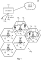
Claims (18)

  1. An apparatus for a wireless communication system, wherein
    the apparatus is to transmit a reference signal on a common set of resource elements, REs, the common set of REs used by one or more further apparatuses in the wireless communication system to transmit the reference signal so that the reference signals of the apparatus and of the one or more further apparatuses use the same REs,
    wherein the apparatus is to
    - transmit the reference signal using a plurality of OFDM symbols, each OFDM symbol having a comb structure, and some or all of the OFDM symbols having different comb offsets, and
    - apply the same sequence to each OFDM symbol, the sequence having a zero auto correlation property, the apparatus and the one or more further apparatus using for a common RE the same sequence, and
    wherein the apparatus is to apply a phase correction to an OFDM symbol before transmission, wherein the phase correction is applied in the time domain or in the frequency domain by multiplying the ODFM symbol with a correction factor ec , and wherein the correction factor ec depends on the comb factor and the comb offset of the OFDM symbol and is independent of the resource element.
  2. An apparatus of claim 1, wherein
    the sequence is a cyclic shifted base sequence,
    the apparatus is to apply the same cyclic shifted basis sequence to each OFDM symbol, the cyclic-shifted base sequence having a zero auto correlation property,
    wherein the correction factor ec depends on the comb factor, the comb offset of the OFDM symbol and the cyclic shift of the base sequence and is independent of the resource element.
  3. An apparatus of claim 1 or 2, wherein
    the sequence is a sequence with no cyclic shift, or the apparatus does not take into account the cyclic shift for the calculation of the correction factor,
    the apparatus is to apply the same sequence to each OFDM symbol, the base sequence having a zero auto correlation property,
    wherein the correction factor ec depends on the comb offset and comb factor of the OFDM symbol only.
  4. An apparatus of any one of the preceding claims, wherein the apparatus is to transmit the reference signal on a common set of REs used by one or more antenna ports of the apparatus to transmit the reference signal, and wherein for each antenna port a different cyclic shift may be used.
  5. An apparatus of any one of the preceding claims, wherein the resource or resource set of the reference signal is configured so that the apparatuses are distinguished by a first correction factor, and wherein the antenna ports of the apparatus are distinguished by second correction factor, the first correction factor implementing a coarser cyclic shift then the second correction factor.
  6. An apparatus of any one of the preceding claims, wherein the apparatus is configured with the cyclic shifts n SRS cs , i
    Figure imgb0146
    of the sequence, wherein n SRS cs , i
    Figure imgb0147
    is derived from a configuration parameter n SRS cs
    Figure imgb0148
    and wherein the range of n SRS cs , i
    Figure imgb0149
    may be extended as follows: n SRS cs , i = n SRS cs + n SRS cs , max p i 1000 N AP mod K TC n SRS cs , max ,
    Figure imgb0150
    or n SRS cs , i = n SRS cs K TC + n SRS cs , max p i 1000 N AP mod n SRS cs , max ,
    Figure imgb0151
    or n SRS cs , i = n SRS cs K TC + n SRS cs , max p i 1000 N AP mod K TC n SRS cs , max .
    Figure imgb0152
    where
    n SRS cs
    Figure imgb0153
    configuration parameter,
    n SRS cs , i
    Figure imgb0154
    resulting parameter used to configure the cyclic shift for the antenna port i,
    n SRS cs , max
    Figure imgb0155
    maximum number of cyclic shifts,
    pi antenna port identifier
    N AP number of the antenna ports,
    K TC transmission comb value.
  7. The apparatus of any one of the preceding claims, wherein the correction factor ec applied to the l'-th OFDM symbol is given by: e α i , Δk p i , K TC = e j φ 1 α i , Δk p i , K TC + φ 2 Δk p i , K TC , a i
    Figure imgb0156
    with φ 1 α i , Δk p i , K TC = α i Δk p i K TC ,
    Figure imgb0157
    and φ 2 Δk p i , K TC , a i = 2 π Δk p i K TC a i ,
    Figure imgb0158
    where
    K TC transmission comb value
    ai ∈ [0..K TC[ an integer value, e.g., received as configuration parameter or determined by other means)
    Δk(pi,l') relative comb offset value of the l'-th SRS OFDM for antenna port pi .

  8. The apparatus of any one of claims 1 to 6, wherein the correction factor ec applied to the l'-th OFDM symbol is given by: e α i , Δk p i , K TC = e i Δk p i K TC .
    Figure imgb0159
    where
    K TC transmission comb value
    Δk(pi,l') relative comb offset value of the l'-th SRS OFDM for antenna port pi .
  9. The apparatus of any one of claims 1 to 6, wherein the correction factor ec applied to the l'-th OFDM symbol is given by: e α i , Δk p i , K TC = e i eff Δk p i K TC .
    Figure imgb0160
    with α i eff = 2 π n SRS effcs , i n SRS cs , max
    Figure imgb0161
    n SRS cs , i = n SRS effcs , i mod n SRS cs , max
    Figure imgb0162
    where
    K TC transmission comb value,
    Δk(pi ,l') relative comb offset value of the l'-th SRS OFDM for antenna port pi,
    n SRS cs , max
    Figure imgb0163
    maximum number of cyclic shifts,
    n SRS cs , i
    Figure imgb0164
    configured cyclic shift value,
    α i eff
    Figure imgb0165
    is calculated by α i eff = 2 π n SRS effcs , i n SRS cs , max
    Figure imgb0166
    with n SRS cs , i = n SRS effcs , i mod n SRS cs , max .
    Figure imgb0167
    n SRS effcs , i
    Figure imgb0168
    effective cyclic shift.
  10. The apparatus of any one of claims 7 to 9, wherein the apparatus is configured with n SRS effcs , i ,
    Figure imgb0169
    or n SRS effcs ,
    Figure imgb0170
    or n SRS cs ,
    Figure imgb0171
    or ai via a higher layer, e. g., using RRC signaling, or via the physical layer.
  11. The apparatus of any one of the preceding claims, wherein the apparatus is to apply the correction factor ec after the OFDM symbol generation or during the OFDM symbol generation,
    wherein the apparatus is to apply the correction factor ec to the OFDM symbol r (pi )(k',l') during the mapping of the resource elements on the time-frequency grid for the antenna port pi as a K T C k ʹ + k 0 p i , l ʹ + l o p i = { 1 N AP β SRS e α i , Δk p i , K TC r p i = 0 , 1 , , M sc , b RS 1 = 0 , 1 , N symb SRS 1 0 otherwise . ,
    Figure imgb0172
    where
    K TC transmission comb value,
    k 0 p i
    Figure imgb0173
    frequency domain starting position for antenna port pi,
    l 0 index of OFDM symbol within the slot containing where the SRS transmission starts,
    Δk(pi,l') relative comb offset value of the l'-th SRS OFDM for antenna port pi ,
    N AP number of the antenna ports,
    β SRS amplitude scaling factor to adjust transmit power,
    M sc , b RS
    Figure imgb0174
    the number of resource blocks used for transmitting SRS
    N symb SRS
    Figure imgb0175
    number of SRS symbols within a resource,
    or wherein the apparatus is to apply the correction factor ec to the sequence r (pi )(n,l') such that the phase-corrected OFDM symbol before mapping on the time frequency resources is given by r ˜ p i n = e α i , Δk p i , K TC r p i n , 0 n M sc , b RS 1 ,
    Figure imgb0176
    with r (pi )(n,l') = einr (pi ) r u,v (n) being the cyclic shifted base sequence, l' = 0 , 1 , , N symb SRS 1 ,
    Figure imgb0177
    where
    K TC transmission comb value,
    Δk(pi,l') relative comb offset value of the l'-th SRS OFDM for antenna port pi ,
    M sc , b RS
    Figure imgb0178
    the number of resource blocks used for transmitting SRS,
    N symb SRS
    Figure imgb0179
    number of SRS symbols within a resource.
  12. The apparatus of any one of the preceding claims, wherein the sequence is a sounding reference signal, SRS, sequence or a positioning reference signal, PRS, sequence.
  13. A reference signal to be used in a wireless communication system, wherein
    the reference signal is to be transmitted on a common set of resource elements, REs, the common set of REs used by a plurality of apparatuses in the wireless communication system to transmit the reference signals use the common set of REs,
    the reference signal is to use a plurality of OFDM symbols, each OFDM symbol having a comb structure, and some or all of the OFDM symbol having different comb offsets,
    the reference signal is obtained by applying the same sequence to each OFDM symbol, the base sequence having a zero auto correlation property, the apparatus and the one or more further apparatus using for a common RE the same sequence, and
    the reference signal includes a phase correction applied in the time domain or in the frequency domain by multiplying the ODFM symbol with a correction factor ec , and wherein the correction factor ec depends on the comb factor and the comb offset of the OFDM symbol and is independent of the resource element.
  14. A wireless communication system, the wireless communication system comprising one or more apparatus of any one of claims 1 to 12 and/or employing a reference signal of claim 13.
  15. The wireless communication system of claim 14, further comprising one or more receivers, wherein each of the apparatuses is to transmit one or more respective reference signals, and wherein the receiver is to determine a position of the respective UEs using the received reference signals according to the time difference of arrival, TODA, technique.
  16. The wireless communication system of claim 15, wherein
    the plurality of apparatuses are user devices, UEs, wherein some or all of the UEs are organized in two or more groups, each group using the common REs, and the UEs of a group using base sequences separated by respective cyclic shifts only, and wherein the UEs belonging to one group may transmit in a subset of slots only, e.g., using an activation or muting pattern, or
    the one or more apparatuses comprise a user device, UE, and wherein the UE is to transmit the reference signal over several antenna ports in parallel and the receiver is to use the known time difference to calculate a combined channel interference ration, CIR, or
    the one or more apparatuses comprise a base station, BS, and wherein the BS is to transmit the reference signal over several antenna ports in parallel, or
    the one or more apparatuses are to transmit the reference signal over several antenna ports in parallel, and the wireless communication system is to measure the delay of the several antenna ports in parallel.
  17. A method for transmitting reference signals in a wireless communication system, the method comprising:
    transmitting, by a plurality of apparatuses of the wireless communication system, reference signals use a common set of resource elements, REs,
    wherein the reference signal is transmitted using a plurality of OFDM symbols, each OFDM symbol having a comb structure, and some or all of the OFDM symbol having different comb offsets,
    wherein the same sequence is applied to each OFDM symbol, the base sequence having a zero auto correlation property, the apparatus and the one or more further apparatuses using for a common RE the same sequence, and
    wherein a phase correction is applied to an OFDM symbol before transmission, wherein the phase correction is applied in the time domain or in the frequency domain by multiplying the ODFM symbol with a correction factor e c , and wherein the correction factor ec depends on the comb factor and the comb offset of the OFDM symbol and is independent of the resource element.
  18. A non-transitory computer program product comprising a computer readable medium storing instructions which, when executed on a computer, perform the method of claim 17.
EP19209790.5A 2019-11-07 2019-11-18 Ambiguity/aliasing cancellation or reduction for staggered reference signals Withdrawn EP3820102A1 (en)

Priority Applications (4)

Application Number Priority Date Filing Date Title
EP20799756.0A EP4055789B1 (en) 2019-11-07 2020-11-05 Ambiguity/aliasing cancellation or reduction for staggered reference signals
PCT/EP2020/081187 WO2021089732A1 (en) 2019-11-07 2020-11-05 Ambiguity/aliasing cancellation or reduction for staggered reference signals
CN202080092001.7A CN114946162B (en) 2019-11-07 2020-11-05 Blurring/aliasing removal or reduction for interleaved reference signals
US17/731,493 US12267197B2 (en) 2019-11-07 2022-04-28 Ambiguity/aliasing cancellation or reduction for staggered reference signals

Applications Claiming Priority (1)

Application Number Priority Date Filing Date Title
EP19207826.9A EP3820101A1 (en) 2019-11-07 2019-11-07 Ambiguity/aliasing cancellation or reduction for staggered reference signals

Publications (1)

Publication Number Publication Date
EP3820102A1 true EP3820102A1 (en) 2021-05-12

Family

ID=68502982

Family Applications (3)

Application Number Title Priority Date Filing Date
EP19207826.9A Withdrawn EP3820101A1 (en) 2019-11-07 2019-11-07 Ambiguity/aliasing cancellation or reduction for staggered reference signals
EP19209790.5A Withdrawn EP3820102A1 (en) 2019-11-07 2019-11-18 Ambiguity/aliasing cancellation or reduction for staggered reference signals
EP20799756.0A Active EP4055789B1 (en) 2019-11-07 2020-11-05 Ambiguity/aliasing cancellation or reduction for staggered reference signals

Family Applications Before (1)

Application Number Title Priority Date Filing Date
EP19207826.9A Withdrawn EP3820101A1 (en) 2019-11-07 2019-11-07 Ambiguity/aliasing cancellation or reduction for staggered reference signals

Family Applications After (1)

Application Number Title Priority Date Filing Date
EP20799756.0A Active EP4055789B1 (en) 2019-11-07 2020-11-05 Ambiguity/aliasing cancellation or reduction for staggered reference signals

Country Status (4)

Country Link
US (1) US12267197B2 (en)
EP (3) EP3820101A1 (en)
CN (1) CN114946162B (en)
WO (1) WO2021089732A1 (en)

Cited By (2)

* Cited by examiner, † Cited by third party
Publication number Priority date Publication date Assignee Title
WO2023164853A1 (en) * 2022-03-02 2023-09-07 北京小米移动软件有限公司 Srs sending method and apparatus, srs receiving method and apparatus, device, medium, and product
EP4494273A4 (en) * 2022-03-16 2026-03-25 Samsung Electronics Co Ltd METHOD AND DEVICE FOR AN SRS METHOD

Families Citing this family (13)

* Cited by examiner, † Cited by third party
Publication number Priority date Publication date Assignee Title
BR112021021779A2 (en) * 2019-05-02 2021-12-28 Lg Electronics Inc Method for transmitting and receiving signals in a wireless communication system, and device supporting the same
CN117546568A (en) * 2020-06-18 2024-02-09 日本电气株式会社 Method, apparatus and computer storage medium for communication
EP4193579A1 (en) * 2020-08-06 2023-06-14 Fraunhofer-Gesellschaft zur Förderung der angewandten Forschung e.V. Apparatus and method for a wireless communication system employing cyclic shift hopping
CN116250195A (en) * 2020-09-29 2023-06-09 华为技术有限公司 Method and device for reporting interference
CN115943707B (en) * 2021-08-05 2026-03-24 苹果公司 SRS signaling in 5G New Radio wireless communication
CN116015576B (en) * 2021-10-22 2026-02-10 北京紫光展锐通信技术有限公司 Reference signal resource mapping method and apparatus, terminal and network equipment
KR20230087003A (en) * 2021-12-09 2023-06-16 삼성전자주식회사 Pilot power control for non-linearity compensation of power amplifier
CN116996175A (en) * 2022-04-20 2023-11-03 大唐移动通信设备有限公司 Information transmission methods, devices, terminal equipment and network equipment
JP2025114883A (en) * 2022-06-22 2025-08-06 シャープ株式会社 Terminal device, base station device, and communication method
US20240314008A1 (en) * 2023-03-13 2024-09-19 Mediatek Inc. Joint communication and sensing method and related user equipment for orthogonal frequency domain multiplexing communication system
CN120263360A (en) * 2023-04-07 2025-07-04 华为技术有限公司 A communication method and device
CN117130006B (en) * 2023-08-24 2024-05-03 光维(广东)科技有限公司 Automatic aliasing elimination double-optical comb ranging device and method
FI20245044A1 (en) * 2024-01-18 2025-07-19 Nokia Solutions & Networks Oy Controlling transmissions

Family Cites Families (12)

* Cited by examiner, † Cited by third party
Publication number Priority date Publication date Assignee Title
RU2496245C2 (en) * 2009-04-27 2013-10-20 Хуавэй Текнолоджиз Ко., Лтд. Positioning reference signals
US9137076B2 (en) * 2009-10-30 2015-09-15 Qualcomm Incorporated Method and apparatus for mutiplexing reference signal and data in a wireless communication system
JP2012114901A (en) * 2010-11-05 2012-06-14 Sharp Corp Mobile station device, base station device and method, and integrated circuit
CN102223726A (en) 2011-06-10 2011-10-19 中兴通讯股份有限公司 Method and system for sending SRS (survey reference signal)
US9491575B2 (en) * 2014-06-13 2016-11-08 Qualcomm Incorporated Positioning beacons with wireless backhaul
US10333671B2 (en) * 2015-04-06 2019-06-25 Lg Electronics Inc. Method for transmitting and receiving signal based on shared resource in wireless communication system, and apparatus therefor
EP3281347B1 (en) * 2015-04-10 2021-06-02 Telefonaktiebolaget LM Ericsson (publ) Enhanced positioning reference signal patterns for positioning
EP3352404B1 (en) * 2015-09-14 2020-12-23 LG Electronics Inc. Method for correcting frequency offset in v2v communication and device for same
WO2017200315A1 (en) * 2016-05-18 2017-11-23 엘지전자(주) Method for tracking phase noise in wireless communication system, and apparatus therefor
PL3523911T3 (en) * 2016-10-10 2026-04-20 Telefonaktiebolaget Lm Ericsson (Publ) Common reference signal design for ofdm and dfts-ofdm
US11015975B2 (en) * 2017-05-15 2021-05-25 The Trustees Of Princeton University Fast computational phase and timing correction for multiheterodyne spectroscopy
CN108260219B (en) * 2018-01-12 2021-11-12 中兴通讯股份有限公司 Method, device and computer readable storage medium for receiving and transmitting reference signal

Non-Patent Citations (4)

* Cited by examiner, † Cited by third party
Title
FRAUNHOFER IIS ET AL: "Details on Uplink PRS Signal Design", vol. RAN WG1, no. Reno, US; 20190513 - 20190517, 3 May 2019 (2019-05-03), XP051709117, Retrieved from the Internet <URL:http://www.3gpp.org/ftp/tsg%5Fran/WG1%5FRL1/TSGR1%5F97/Docs/R1%2D1907088%2Ezip> [retrieved on 20190503] *
FRAUNHOFER IIS ET AL: "Remaining details on SRS enhancements for positioning", vol. RAN WG1, no. Reno, NV, USA; 20191118 - 20191122, 8 November 2019 (2019-11-08), XP051820305, Retrieved from the Internet <URL:https://ftp.3gpp.org/tsg_ran/WG1_RL1/TSGR1_99/Docs/R1-1913101.zip R1-1913101_UL_PRS_Signal_Design.docx> [retrieved on 20191108] *
HUAWEI ET AL: "SRS design for NR positioning", vol. RAN WG1, no. Chongqing, China; 20191014 - 20191020, 9 October 2019 (2019-10-09), XP051790105, Retrieved from the Internet <URL:http://www.3gpp.org/ftp/tsg_ran/WG1_RL1/TSGR1_98b/Docs/R1-1911343.zip> [retrieved on 20191009] *
QUALCOMM INCORPORATED: "RAT-dependent DL-only NR positioning techniques", vol. RAN WG1, no. Taipei, Taiwan; 20190121 - 20190125, 12 January 2019 (2019-01-12), XP051576451, Retrieved from the Internet <URL:http://www.3gpp.org/ftp/tsg%5Fran/WG1%5FRL1/TSGR1%5FAH/NR%5FAH%5F1901/Docs/R1%2D1900914%2Ezip> [retrieved on 20190112] *

Cited By (2)

* Cited by examiner, † Cited by third party
Publication number Priority date Publication date Assignee Title
WO2023164853A1 (en) * 2022-03-02 2023-09-07 北京小米移动软件有限公司 Srs sending method and apparatus, srs receiving method and apparatus, device, medium, and product
EP4494273A4 (en) * 2022-03-16 2026-03-25 Samsung Electronics Co Ltd METHOD AND DEVICE FOR AN SRS METHOD

Also Published As

Publication number Publication date
US20220271982A1 (en) 2022-08-25
CN114946162B (en) 2024-06-28
EP4055789A1 (en) 2022-09-14
CN114946162A (en) 2022-08-26
WO2021089732A1 (en) 2021-05-14
US12267197B2 (en) 2025-04-01
EP4055789B1 (en) 2023-12-20
EP3820101A1 (en) 2021-05-12

Similar Documents

Publication Publication Date Title
EP4055789B1 (en) Ambiguity/aliasing cancellation or reduction for staggered reference signals
EP3703435B1 (en) Method for transmitting positioning information by terminal in wireless communication system supporting sidelink, a device therefor, a method for transmitting a positioning signal by the network
JP7242790B2 (en) Method and Apparatus for Transmitting Discovery Signals and Method and Apparatus for Receiving Discovery Signals
US12457143B2 (en) Apparatus and method for a wireless communication system employing cyclic shift hopping
AU2018261298B2 (en) Method for transmitting and receiving random access channel, and device for same
EP3771248B1 (en) Method for determining transmission beam in wireless communication system supporting sidelink, and terminal therefor
US12082223B2 (en) Methods and apparatuses for resource allocation in a telecommunications network
US11582006B2 (en) Window for transmitting a positioning reference signal
US12388600B2 (en) Flexible SRS sounding for NR systems
US20240163908A1 (en) Positioning for user equipments with limited capabilities
CN116745633A (en) Positioning reference signaling for position measurement in wireless communication systems
US20240283581A1 (en) Apparatus and Method for Providing a Modified OFDM Frame Structure
US20250227012A1 (en) Transceiver

Legal Events

Date Code Title Description
PUAI Public reference made under article 153(3) epc to a published international application that has entered the european phase

Free format text: ORIGINAL CODE: 0009012

STAA Information on the status of an ep patent application or granted ep patent

Free format text: STATUS: THE APPLICATION HAS BEEN PUBLISHED

AK Designated contracting states

Kind code of ref document: A1

Designated state(s): AL AT BE BG CH CY CZ DE DK EE ES FI FR GB GR HR HU IE IS IT LI LT LU LV MC MK MT NL NO PL PT RO RS SE SI SK SM TR

STAA Information on the status of an ep patent application or granted ep patent

Free format text: STATUS: THE APPLICATION IS DEEMED TO BE WITHDRAWN

18D Application deemed to be withdrawn

Effective date: 20211113

RAP3 Party data changed (applicant data changed or rights of an application transferred)

Owner name: FRAUNHOFER-GESELLSCHAFT ZUR FOERDERUNG DER ANGEWANDTEN FORSCHUNG E.V.