EP3820032A1 - Power converter monitor and method of use - Google Patents
Power converter monitor and method of use Download PDFInfo
- Publication number
- EP3820032A1 EP3820032A1 EP20204447.5A EP20204447A EP3820032A1 EP 3820032 A1 EP3820032 A1 EP 3820032A1 EP 20204447 A EP20204447 A EP 20204447A EP 3820032 A1 EP3820032 A1 EP 3820032A1
- Authority
- EP
- European Patent Office
- Prior art keywords
- power
- fault
- power converter
- converter
- monitor
- Prior art date
- Legal status (The legal status is an assumption and is not a legal conclusion. Google has not performed a legal analysis and makes no representation as to the accuracy of the status listed.)
- Pending
Links
- 238000000034 method Methods 0.000 title claims description 19
- 238000006243 chemical reaction Methods 0.000 claims description 24
- 230000002401 inhibitory effect Effects 0.000 claims description 3
- 238000012544 monitoring process Methods 0.000 claims description 3
- 238000011084 recovery Methods 0.000 claims description 3
- 238000012358 sourcing Methods 0.000 description 3
- 238000003745 diagnosis Methods 0.000 description 1
- 238000010586 diagram Methods 0.000 description 1
- 238000004146 energy storage Methods 0.000 description 1
- 238000012986 modification Methods 0.000 description 1
- 230000004048 modification Effects 0.000 description 1
- 230000007704 transition Effects 0.000 description 1
Images


Classifications
-
- H—ELECTRICITY
- H02—GENERATION; CONVERSION OR DISTRIBUTION OF ELECTRIC POWER
- H02H—EMERGENCY PROTECTIVE CIRCUIT ARRANGEMENTS
- H02H7/00—Emergency protective circuit arrangements specially adapted for specific types of electric machines or apparatus or for sectionalised protection of cable or line systems, and effecting automatic switching in the event of an undesired change from normal working conditions
- H02H7/10—Emergency protective circuit arrangements specially adapted for specific types of electric machines or apparatus or for sectionalised protection of cable or line systems, and effecting automatic switching in the event of an undesired change from normal working conditions for converters; for rectifiers
- H02H7/12—Emergency protective circuit arrangements specially adapted for specific types of electric machines or apparatus or for sectionalised protection of cable or line systems, and effecting automatic switching in the event of an undesired change from normal working conditions for converters; for rectifiers for static converters or rectifiers
- H02H7/1203—Circuits independent of the type of conversion
-
- H—ELECTRICITY
- H02—GENERATION; CONVERSION OR DISTRIBUTION OF ELECTRIC POWER
- H02M—APPARATUS FOR CONVERSION BETWEEN AC AND AC, BETWEEN AC AND DC, OR BETWEEN DC AND DC, AND FOR USE WITH MAINS OR SIMILAR POWER SUPPLY SYSTEMS; CONVERSION OF DC OR AC INPUT POWER INTO SURGE OUTPUT POWER; CONTROL OR REGULATION THEREOF
- H02M1/00—Details of apparatus for conversion
- H02M1/32—Means for protecting converters other than automatic disconnection
-
- B—PERFORMING OPERATIONS; TRANSPORTING
- B64—AIRCRAFT; AVIATION; COSMONAUTICS
- B64D—EQUIPMENT FOR FITTING IN OR TO AIRCRAFT; FLIGHT SUITS; PARACHUTES; ARRANGEMENT OR MOUNTING OF POWER PLANTS OR PROPULSION TRANSMISSIONS IN AIRCRAFT
- B64D41/00—Power installations for auxiliary purposes
-
- B—PERFORMING OPERATIONS; TRANSPORTING
- B64—AIRCRAFT; AVIATION; COSMONAUTICS
- B64F—GROUND OR AIRCRAFT-CARRIER-DECK INSTALLATIONS SPECIALLY ADAPTED FOR USE IN CONNECTION WITH AIRCRAFT; DESIGNING, MANUFACTURING, ASSEMBLING, CLEANING, MAINTAINING OR REPAIRING AIRCRAFT, NOT OTHERWISE PROVIDED FOR; HANDLING, TRANSPORTING, TESTING OR INSPECTING AIRCRAFT COMPONENTS, NOT OTHERWISE PROVIDED FOR
- B64F5/00—Designing, manufacturing, assembling, cleaning, maintaining or repairing aircraft, not otherwise provided for; Handling, transporting, testing or inspecting aircraft components, not otherwise provided for
- B64F5/60—Testing or inspecting aircraft components or systems
-
- H—ELECTRICITY
- H02—GENERATION; CONVERSION OR DISTRIBUTION OF ELECTRIC POWER
- H02M—APPARATUS FOR CONVERSION BETWEEN AC AND AC, BETWEEN AC AND DC, OR BETWEEN DC AND DC, AND FOR USE WITH MAINS OR SIMILAR POWER SUPPLY SYSTEMS; CONVERSION OF DC OR AC INPUT POWER INTO SURGE OUTPUT POWER; CONTROL OR REGULATION THEREOF
- H02M1/00—Details of apparatus for conversion
- H02M1/32—Means for protecting converters other than automatic disconnection
- H02M1/325—Means for protecting converters other than automatic disconnection with means for allowing continuous operation despite a fault, i.e. fault tolerant converters
-
- H—ELECTRICITY
- H02—GENERATION; CONVERSION OR DISTRIBUTION OF ELECTRIC POWER
- H02M—APPARATUS FOR CONVERSION BETWEEN AC AND AC, BETWEEN AC AND DC, OR BETWEEN DC AND DC, AND FOR USE WITH MAINS OR SIMILAR POWER SUPPLY SYSTEMS; CONVERSION OF DC OR AC INPUT POWER INTO SURGE OUTPUT POWER; CONTROL OR REGULATION THEREOF
- H02M1/00—Details of apparatus for conversion
- H02M1/36—Means for starting or stopping converters
Definitions
- the present disclosure relates to a power converter, and more particularly to a power converter having built in fault containment.
- DC-to-DC converters and DC-to-AC converters are used anytime a conversion from one voltage to another voltage is needed, such as 270 volts to 28V.
- a TRU transformer-rectifier unit
- AC-to AC a transformer is used.
- a power converter When starting with DC at the input, a power converter must be used.
- Converters must be fault tolerant such that they protect both the output cabling and themselves from faults on one or more outputs. If a converter is sourcing a fault, and the input power source is inadequate to source the fault, the Power Converter input source will droop, causing the Power Converter to momentarily lose power. It is possible that the converter's input source power is inadequate to source a fault on the output of the Power Converter. This situation represents improper trip coordination, but is not detectable, and therefore represents a "dormant" fault. In such a situation, the Power Converter input voltage can collapse before the Power Converter can respond to the downstream fault according to its own design parameters. This can result in the Power Converter becoming unpowered momentarily and losing knowledge that the fault is present.
- a power converter monitor for an aircraft environment, having built-in fault tolerance and containment includes a plurality of voltage inputs operatively connected to a pulse timing device, a respective comparator electrically connected to each of the voltage inputs, an and-gate electrically connected in series to each of the comparators, wherein the pulse timing device is operatively connected by the and-gate and a-not gate to each of the voltage inputs configured to reset a detected voltage output fault and provide a converter inhibit pulse if the voltage output fault is detected.
- Comparator output can pass through a respective flip-flop device.
- the comparators in turn drive the flip-flops, which in turn drive the pulse timing device through the AND gate.
- the flip-flops "remember” if the outputs have risen to an acceptable output voltage since Converter Enable became active.
- the power converter monitor does not include a microprocessor.
- the pulse timing device can include a stand-alone power supply with hold-up capacitance. The amount of hold-up is sufficient for the monitor to continue operating for as long as necessary for the input voltage to return.
- the pulse timing device can be a low power digital counter, a low power analog or digital one-shot.
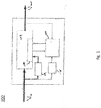
- Fig. 1 a partial view of an exemplary embodiment of a power converter schematic in accordance with the disclosure is shown in Fig. 1 and is designated generally by reference character 100.
- Other aspects of the converter in accordance with the disclosure, or aspects thereof, are provided in Figs. 2 and 3 , as will be described.
- the methods and systems of the invention can be used to manage the output of power converters with active over current protection and to reduce the risk of doorbelling and other power interruption faults in power converters.
- Fig. 1 shows an internal schematic of a power converter 100.
- the power converter is used to convert input power to a different voltage output power as discussed previously.
- the power converter 100 is intended to be used in an aircraft environment.
- the converter includes a power converter monitor 101 and a power conversion module 103 including a conversion control module 107, and a control power 109 operatively connected to the conversion control module 107 for powering the power conversion module 103.
- the comparator 106a-c output passes through a flip-flop device 115a-c.
- the comparators 106a-c drive the flip-flops, which in turn drive the pulse timing device 104 through the AND gate 108.
- the flip-flops 115a-c "remember” if the outputs have risen to an acceptable output voltage since Converter Enable became active.
- the pulse timing device 104 is operatively connected by the and-gate 108 and a-not gate 110 to each of the voltage inputs 102a-c and configured to reset a detected voltage output fault and provide a converter inhibit pulse if the voltage output fault is detected.
- the power converter 100 is not connected to and does not include a microprocessor, which can be expensive, especially when meeting the requirements of DO-178, which is required in aerospace situations.
- the pulse timing device 104 includes a stand-alone power supply with hold-up capacitance 105 (shown in in Fig. 1 ) which allows for the device to keep functioning and monitoring when a power interruption happens.
- the pulse timing device 104 is considered to be a low power digital counter, or an analog or digital one-shot.
- a method 300 for operating the power converter includes detecting 302 an input power fault by a pulse timing device, classifying 304 the fault as a true fault or a power interruption, wherein the state of the Inhibit Lockout signal, at the time the converter enable signal transitions inactive, determines the classification, and inhibiting 306 power conversion by a pulse for a predefined period of time in order to prevent a fault loop, or doorbelling, if the fault is a true fault.
- the inhibit pulse is sent to the control of the power converter.
- Output voltage is used in detecting the power fault. If a power interruption occurs at a time prior to all outputs producing an acceptable output, it is assumed that a fault on one or more outputs produced the input droop. In this case, power conversion will be inhibited for a period of time. This period is for a predetermined amount of time based on thermal recovery of the power converter.
- a high-wattage Power Converter requires profoundly more internal control power than a monitor circuit.
- the demand on this internal control power supply can be substantial when commutating large switching devices. This means that energy storage to "hold up" internal control power through power interruptions can also be impractically large.
- a power converter comprising: a power conversion module including a conversion control module therein; a control power operatively connected to the conversion control module for powering the power conversion module; a power converter monitor having built-in fault tolerance and containment comprising: a plurality of voltage inputs operatively connected to a pulse timing device; a respective comparator amplifier electrically connected to each of the voltage inputs; an and-gate electrically connected in series to each of the comparators; and wherein the pulse timing device is operatively connected by the and-gate and a-not gate to each of the voltage inputs configured to reset a detected voltage output fault and provide a converter inhibit pulse if the voltage output fault is detected.
Landscapes
- Engineering & Computer Science (AREA)
- Power Engineering (AREA)
- Dc-Dc Converters (AREA)
- Aviation & Aerospace Engineering (AREA)
- Manufacturing & Machinery (AREA)
- Transportation (AREA)
- Inverter Devices (AREA)
Abstract
Description
- The present disclosure relates to a power converter, and more particularly to a power converter having built in fault containment.
- DC-to-DC converters and DC-to-AC converters are used anytime a conversion from one voltage to another voltage is needed, such as 270 volts to 28V. For conversion from AC to DC, a TRU (transformer-rectifier unit) is used, for AC-to AC, a transformer is used. When starting with DC at the input, a power converter must be used.
- Converters must be fault tolerant such that they protect both the output cabling and themselves from faults on one or more outputs. If a converter is sourcing a fault, and the input power source is inadequate to source the fault, the Power Converter input source will droop, causing the Power Converter to momentarily lose power. It is possible that the converter's input source power is inadequate to source a fault on the output of the Power Converter. This situation represents improper trip coordination, but is not detectable, and therefore represents a "dormant" fault. In such a situation, the Power Converter input voltage can collapse before the Power Converter can respond to the downstream fault according to its own design parameters. This can result in the Power Converter becoming unpowered momentarily and losing knowledge that the fault is present.
- When the Power Converter loses input power, and hence stops converting power, it is no longer sourcing the fault, and the overload of the input power source is removed. The source power then returns, the power converter attempts to restore output power, and resumes sourcing the same fault. This cycle continues to repeat, and is called "doorbelling". If the doorbelling condition persists, damage to the Power Converter can occur. A microprocessor solution has been previously used to solve the doorbelling problem. However, especially in an aerospace application that imposes DO-178 processes on any embedded software, the microprocessor solution can be too expensive and cumbersome, and there exists a need to address power converters that are powered by another power converter with active over current protection. Accordingly, there is still a need in the art for a power converter fault detector having improved reliability and simplicity that is economically viable. The present disclosure may provide a solution for at least one of these remaining challenges.
- A power converter monitor, for an aircraft environment, having built-in fault tolerance and containment includes a plurality of voltage inputs operatively connected to a pulse timing device, a respective comparator electrically connected to each of the voltage inputs, an and-gate electrically connected in series to each of the comparators, wherein the pulse timing device is operatively connected by the and-gate and a-not gate to each of the voltage inputs configured to reset a detected voltage output fault and provide a converter inhibit pulse if the voltage output fault is detected. Comparator output can pass through a respective flip-flop device. The comparators in turn drive the flip-flops, which in turn drive the pulse timing device through the AND gate. The flip-flops "remember" if the outputs have risen to an acceptable output voltage since Converter Enable became active. The power converter monitor does not include a microprocessor.
- The pulse timing device can include a stand-alone power supply with hold-up capacitance. The amount of hold-up is sufficient for the monitor to continue operating for as long as necessary for the input voltage to return. The pulse timing device can be a low power digital counter, a low power analog or digital one-shot.
- A method of operating the power converter is also disclosed, the method includes operating a power converter, detecting an input power fault by a pulse timing device within a power conversion monitor, classifying the fault as a true fault or a power interruption and inhibiting power conversion by sending an inhibit pulse to the conversion control for a predefined period of time in order to prevent an endless fault loop if the fault is a true fault. Output voltage can be used in detecting the power fault. The fault can cause a doorbelling of the power converter. Power conversion can be inhibited for a predetermined amount of time based on thermal recovery of the power converter. The method can also include restarting the power converter without sending a converter inhibit pulse if a power output is above a predetermined threshold.
- These and other features of the systems and methods of the subject disclosure will become more readily apparent to those skilled in the art from the following detailed description of the preferred embodiments taken in conjunction with the drawings.
- So that those skilled in the art to which the subject invention appertains will readily understand how to make and use the devices and methods of the subject invention without undue experimentation, preferred embodiments thereof will be described in detail herein below, by way of example only and with reference to certain figures, wherein:
- Fig. 1
- is a schematic view of a power converter;
- Fig. 2
- is a schematic view of a power converter monitor of
Fig., 1 ; and - Fig. 3
- is a block diagram showing a method of use of the power converter of
Fig. 1 . - Reference will now be made to the drawings wherein like reference numerals identify similar structural features or aspects of the subject invention. For purposes of explanation and illustration, and not limitation, a partial view of an exemplary embodiment of a power converter schematic in accordance with the disclosure is shown in
Fig. 1 and is designated generally byreference character 100. Other aspects of the converter in accordance with the disclosure, or aspects thereof, are provided inFigs. 2 and3 , as will be described. The methods and systems of the invention can be used to manage the output of power converters with active over current protection and to reduce the risk of doorbelling and other power interruption faults in power converters. -
Fig. 1 shows an internal schematic of apower converter 100. The power converter is used to convert input power to a different voltage output power as discussed previously. Thepower converter 100 is intended to be used in an aircraft environment. The converter includes apower converter monitor 101 and apower conversion module 103 including a conversion control module 107, and a control power 109 operatively connected to the conversion control module 107 for powering thepower conversion module 103. -
Fig. 2 shows a detailed version of thepower converter monitor 101 with a plurality of voltage inputs 102 a-c operatively connected to apulse timing device 104. Thepulse timing device 104 produces a pulse of pre-defined duration when a clock input rises while the reset input is inactive. Thepulse timing device 104 could act as a monostable multi-vibrator. A respective comparator 106a-c is electrically connected to each of the voltage inputs 102a-c. An and-gate 108 is electrically connected in series to each of the comparators 106a-c. The comparator 106a-c output a Boolean condition of whether the converter output voltage is exceeding a specified threshold. The comparator 106a-c output passes through a flip-flop device 115a-c. The comparators 106a-c drive the flip-flops, which in turn drive thepulse timing device 104 through theAND gate 108. The flip-flops 115a-c "remember" if the outputs have risen to an acceptable output voltage since Converter Enable became active. Thepulse timing device 104 is operatively connected by the and-gate 108 and a-notgate 110 to each of the voltage inputs 102a-c and configured to reset a detected voltage output fault and provide a converter inhibit pulse if the voltage output fault is detected. Thepower converter 100 is not connected to and does not include a microprocessor, which can be expensive, especially when meeting the requirements of DO-178, which is required in aerospace situations. Thepulse timing device 104 includes a stand-alone power supply with hold-up capacitance 105 (shown in inFig. 1 ) which allows for the device to keep functioning and monitoring when a power interruption happens. Thepulse timing device 104 is considered to be a low power digital counter, or an analog or digital one-shot. - As shown in
Fig. 3 amethod 300 for operating the power converter includes detecting 302 an input power fault by a pulse timing device, classifying 304 the fault as a true fault or a power interruption, wherein the state of the Inhibit Lockout signal, at the time the converter enable signal transitions inactive, determines the classification, and inhibiting 306 power conversion by a pulse for a predefined period of time in order to prevent a fault loop, or doorbelling, if the fault is a true fault. The inhibit pulse is sent to the control of the power converter. Output voltage is used in detecting the power fault. If a power interruption occurs at a time prior to all outputs producing an acceptable output, it is assumed that a fault on one or more outputs produced the input droop. In this case, power conversion will be inhibited for a period of time. This period is for a predetermined amount of time based on thermal recovery of the power converter. - If the power interruption is the result of a fault that occurs while output power is being delivered, the power interruption may be misdiagnosed on the first power droop. The result will be to resume trying to source a fault, at which time the second "droop" will be recognized as fault-induced.
- It is necessary for the monitor to be powered from an internally generated control power source different than the power conversion control. A high-wattage Power Converter requires profoundly more internal control power than a monitor circuit. The demand on this internal control power supply can be substantial when commutating large switching devices. This means that energy storage to "hold up" internal control power through power interruptions can also be impractically large.
- Devices used in Aerospace must recover from a momentary power interruption, per Power Quality requirements in DO-160. Therefore, droop on input power occurring at a time when output voltage is being produced, must not be treated as a fault. Otherwise, the initial mis-diagnosis of a fault introduced during power conversion will not make sense. Output voltage is used to detect mis-coordinated trip, namely because the fault trip is already mis-coordinated, and the system cannot assume the output current will be high enough to sense as a fault, when the system doesn't recognize what output current will cause the input source to collapse.
- The methods and systems of the present disclosure, as described above and shown in the drawings, provide for a power converter with superior properties including increased reliability and stability, and reduced size, weight, complexity, and cost. While the apparatus and methods of the subject disclosure have been showing and described with reference to embodiments, those skilled in the art will readily appreciate that changes and/or modifications may be made thereto without departing from the spirit and score of the subject disclosure.
- Tolerance to power input droop not caused by a load fault, is necessary, and must not cause an inhibit pulse.
- The following clause sets out features of the invention which may or may not presently be claimed in this application but which may form the basis for future amendment or a divisional application.
- A power converter comprising: a power conversion module including a conversion control module therein; a control power operatively connected to the conversion control module for powering the power conversion module; a power converter monitor having built-in fault tolerance and containment comprising: a plurality of voltage inputs operatively connected to a pulse timing device; a respective comparator amplifier electrically connected to each of the voltage inputs; an and-gate electrically connected in series to each of the comparators; and wherein the pulse timing device is operatively connected by the and-gate and a-not gate to each of the voltage inputs configured to reset a detected voltage output fault and provide a converter inhibit pulse if the voltage output fault is detected.
Claims (15)
- A power converter monitor (101) having built-in fault tolerance and containment comprising:a plurality of voltage inputs (102a-c) operatively connected to a pulse timing device (104);a respective comparator (106a-c) electrically connected to each of the voltage inputs;an and-gate (108) electrically connected in series to each of the comparators, the pulse timing device being operatively connected by the and-gate and a-not gate (110) to each of the voltage inputs configured to reset a detected voltage output fault and provide a converter inhibit pulse if the voltage output fault is detected.
- The power converter monitor of claim 1, wherein the power converter monitor does not include a microprocessor.
- The power converter monitor of claim 1 or 2, wherein the pulse timing device includes a power supply with hold-up capacitance (105).
- The power converter monitor of claim 3, wherein the pulse timing device is a low power digital counter.
- The power converter monitor of claim 3, wherein the pulse timing device is a low power analog or digital one-shot.
- The power converter monitor of any preceding claim, wherein the power monitor is in an aircraft environment.
- A power converter (100) comprising:a power conversion module (103) including a conversion control module (107) therein;a control power (109) operatively connected to the conversion control module for powering the power conversion module; andthe power converter monitor of any preceding claim.
- The power converter of claim 7, wherein the pulse timing device includes a stand-alone power supply with hold-up capacitance.
- A method (300) comprising:operating a power converter;detecting (302) an input power fault by a pulse timing device;classifying (304) the fault as a true fault or a power interruption; andinhibiting (306) power conversion by sending an inhibit pulse to the power converter for a predefined period of time in order to prevent an endless fault loop if the fault is a true fault.
- The method of claim 9, wherein output voltage is used in detecting the power fault.
- The method of claim 9 or 10, wherein the fault causes a doorbelling of the power converted.
- The method of claim 9, 10, or 11, wherein power conversion is inhibited for a predetermined amount of time based on thermal recovery of the power converter.
- The method of any of claims 9 to 12, further comprising monitoring a power converter enable signal of the power converter and power input.
- The method of claim 13, wherein monitoring includes passing comparator output through a flip-flop device, the flip-flops remembering if outputs have risen to an acceptable output voltage since a converter enable signal became active.
- The method of any of claims 9 to 14, further comprising restarting the power converter without sending a converter inhibit pulse if a power output was above a predetermined threshold.
Applications Claiming Priority (1)
| Application Number | Priority Date | Filing Date | Title |
|---|---|---|---|
| US16/674,951 US11336083B2 (en) | 2019-11-05 | 2019-11-05 | Power converter monitor and method of use |
Publications (1)
| Publication Number | Publication Date |
|---|---|
| EP3820032A1 true EP3820032A1 (en) | 2021-05-12 |
Family
ID=73037840
Family Applications (1)
| Application Number | Title | Priority Date | Filing Date |
|---|---|---|---|
| EP20204447.5A Pending EP3820032A1 (en) | 2019-11-05 | 2020-10-28 | Power converter monitor and method of use |
Country Status (2)
| Country | Link |
|---|---|
| US (1) | US11336083B2 (en) |
| EP (1) | EP3820032A1 (en) |
Citations (6)
| Publication number | Priority date | Publication date | Assignee | Title |
|---|---|---|---|---|
| JPS6264218A (en) * | 1985-09-11 | 1987-03-23 | 富士電機株式会社 | Defect diagnosing device |
| US5179495A (en) * | 1990-08-02 | 1993-01-12 | Furnas Electric Company | Solid state overload relay |
| JPH05336652A (en) * | 1992-05-28 | 1993-12-17 | Victor Co Of Japan Ltd | Power supply protective circuit for electronic appliance |
| US5978195A (en) * | 1998-02-23 | 1999-11-02 | Goder; Dimitry | Circuit protection arrangement |
| US20040212942A1 (en) * | 2001-03-14 | 2004-10-28 | Balu Balakrishnan | Method and apparatus for fault condition protection of a switched mode power supply |
| US20100103567A1 (en) * | 2008-10-29 | 2010-04-29 | Phoenix Contact Gmbh & Co. Kg | Circuit arrangement for protecting electronic devices against incorrect logic voltages |
Family Cites Families (6)
| Publication number | Priority date | Publication date | Assignee | Title |
|---|---|---|---|---|
| US7495875B2 (en) * | 2007-06-05 | 2009-02-24 | Fsp Technology Inc. | Power abnormal protection circuit |
| US8879283B2 (en) * | 2009-11-05 | 2014-11-04 | On-Bright Electronics (Shanghai) Co., Ltd. | System and method providing protection in the event of current sensing failure for power converter |
| US9106201B1 (en) | 2010-06-23 | 2015-08-11 | Volterra Semiconductor Corporation | Systems and methods for DC-to-DC converter control |
| US8860394B2 (en) | 2012-06-28 | 2014-10-14 | Intersil Americas LLC | Fast dynamic voltage response for voltage regulators with droop control |
| KR102045780B1 (en) | 2013-03-05 | 2019-11-18 | 삼성전자주식회사 | Bidirectional voltage positioning circuit, voltage converter and power supply device including the same |
| DE102014203157A1 (en) * | 2014-02-21 | 2015-08-27 | Airbus Operations Gmbh | Bipolar high voltage network and method for operating a bipolar high voltage network |
-
2019
- 2019-11-05 US US16/674,951 patent/US11336083B2/en active Active
-
2020
- 2020-10-28 EP EP20204447.5A patent/EP3820032A1/en active Pending
Patent Citations (6)
| Publication number | Priority date | Publication date | Assignee | Title |
|---|---|---|---|---|
| JPS6264218A (en) * | 1985-09-11 | 1987-03-23 | 富士電機株式会社 | Defect diagnosing device |
| US5179495A (en) * | 1990-08-02 | 1993-01-12 | Furnas Electric Company | Solid state overload relay |
| JPH05336652A (en) * | 1992-05-28 | 1993-12-17 | Victor Co Of Japan Ltd | Power supply protective circuit for electronic appliance |
| US5978195A (en) * | 1998-02-23 | 1999-11-02 | Goder; Dimitry | Circuit protection arrangement |
| US20040212942A1 (en) * | 2001-03-14 | 2004-10-28 | Balu Balakrishnan | Method and apparatus for fault condition protection of a switched mode power supply |
| US20100103567A1 (en) * | 2008-10-29 | 2010-04-29 | Phoenix Contact Gmbh & Co. Kg | Circuit arrangement for protecting electronic devices against incorrect logic voltages |
Also Published As
| Publication number | Publication date |
|---|---|
| US11336083B2 (en) | 2022-05-17 |
| US20210135448A1 (en) | 2021-05-06 |
Similar Documents
| Publication | Publication Date | Title |
|---|---|---|
| KR101519319B1 (en) | Dc power supply device, and control method for dc power supply device | |
| EP3945655A1 (en) | Method for controlling operation of a module level power electronics device in a photovoltaic system, and photovoltaic system | |
| US11081974B2 (en) | Fault tolerant multilevel modular power conversion device | |
| EP3024134B1 (en) | Parallel inverter system, and shutdown control method and shutdown control device for parallel inverter system | |
| US9071051B2 (en) | Overvoltage protection unit with AC input current sensors | |
| US20200119659A1 (en) | Power conversion device | |
| US20170364040A1 (en) | Access control method for parallel direct current power supplies and device thereof | |
| US11630501B2 (en) | Power monitor | |
| CN106611997B (en) | Uninterruptible power supply system and method | |
| US12113395B2 (en) | Power converter | |
| JP2013162699A (en) | Distributed power supply system and power conversion apparatus | |
| EP3048689B1 (en) | Direct current power system | |
| KR20190132855A (en) | Power conversion system connected grid for supporting grid | |
| US11336083B2 (en) | Power converter monitor and method of use | |
| US12597799B2 (en) | Power supply switching method and apparatus, and multi-power supply system | |
| EP2645554B1 (en) | Converter | |
| JPH10248252A (en) | Charge device for capacitor | |
| JP2016214001A (en) | Uninterruptible power supply system | |
| KR20170111680A (en) | Direct current uninterruptible power supply system | |
| JP4493308B2 (en) | Uninterruptible power supply and uninterruptible power supply system | |
| EP4597812A1 (en) | Three-level boost converter, method and apparatus for controlling three-level boost converter and photovoltaic system | |
| EP2882061B1 (en) | Industrial system phase sag detection | |
| JP2998213B2 (en) | How to operate the power supply | |
| JP7205127B2 (en) | DC power distribution system, control method for DC power distribution system, and power storage device | |
| CN121356131A (en) | Uninterruptible power supply |
Legal Events
| Date | Code | Title | Description |
|---|---|---|---|
| PUAI | Public reference made under article 153(3) epc to a published international application that has entered the european phase |
Free format text: ORIGINAL CODE: 0009012 |
|
| STAA | Information on the status of an ep patent application or granted ep patent |
Free format text: STATUS: THE APPLICATION HAS BEEN PUBLISHED |
|
| AK | Designated contracting states |
Kind code of ref document: A1 Designated state(s): AL AT BE BG CH CY CZ DE DK EE ES FI FR GB GR HR HU IE IS IT LI LT LU LV MC MK MT NL NO PL PT RO RS SE SI SK SM TR |
|
| STAA | Information on the status of an ep patent application or granted ep patent |
Free format text: STATUS: REQUEST FOR EXAMINATION WAS MADE |
|
| 17P | Request for examination filed |
Effective date: 20211112 |
|
| RBV | Designated contracting states (corrected) |
Designated state(s): AL AT BE BG CH CY CZ DE DK EE ES FI FR GB GR HR HU IE IS IT LI LT LU LV MC MK MT NL NO PL PT RO RS SE SI SK SM TR |
|
| STAA | Information on the status of an ep patent application or granted ep patent |
Free format text: STATUS: EXAMINATION IS IN PROGRESS |
|
| 17Q | First examination report despatched |
Effective date: 20220622 |