EP3820026A1 - Electrical machines - Google Patents
Electrical machines Download PDFInfo
- Publication number
- EP3820026A1 EP3820026A1 EP19275117.0A EP19275117A EP3820026A1 EP 3820026 A1 EP3820026 A1 EP 3820026A1 EP 19275117 A EP19275117 A EP 19275117A EP 3820026 A1 EP3820026 A1 EP 3820026A1
- Authority
- EP
- European Patent Office
- Prior art keywords
- cooling
- stator assembly
- cooling plate
- core
- jacket
- Prior art date
- Legal status (The legal status is an assumption and is not a legal conclusion. Google has not performed a legal analysis and makes no representation as to the accuracy of the status listed.)
- Pending
Links
Images



Classifications
-
- H—ELECTRICITY
- H02—GENERATION; CONVERSION OR DISTRIBUTION OF ELECTRIC POWER
- H02K—DYNAMO-ELECTRIC MACHINES
- H02K1/00—Details of the magnetic circuit
- H02K1/06—Details of the magnetic circuit characterised by the shape, form or construction
- H02K1/12—Stationary parts of the magnetic circuit
- H02K1/20—Stationary parts of the magnetic circuit with channels or ducts for flow of cooling medium
-
- H—ELECTRICITY
- H02—GENERATION; CONVERSION OR DISTRIBUTION OF ELECTRIC POWER
- H02K—DYNAMO-ELECTRIC MACHINES
- H02K5/00—Casings; Enclosures; Supports
- H02K5/04—Casings or enclosures characterised by the shape, form or construction thereof
- H02K5/20—Casings or enclosures characterised by the shape, form or construction thereof with channels or ducts for flow of cooling medium
-
- H—ELECTRICITY
- H02—GENERATION; CONVERSION OR DISTRIBUTION OF ELECTRIC POWER
- H02K—DYNAMO-ELECTRIC MACHINES
- H02K3/00—Details of windings
- H02K3/04—Windings characterised by the conductor shape, form or construction, e.g. with bar conductors
- H02K3/12—Windings characterised by the conductor shape, form or construction, e.g. with bar conductors arranged in slots
-
- H—ELECTRICITY
- H02—GENERATION; CONVERSION OR DISTRIBUTION OF ELECTRIC POWER
- H02K—DYNAMO-ELECTRIC MACHINES
- H02K5/00—Casings; Enclosures; Supports
- H02K5/04—Casings or enclosures characterised by the shape, form or construction thereof
- H02K5/20—Casings or enclosures characterised by the shape, form or construction thereof with channels or ducts for flow of cooling medium
- H02K5/203—Casings or enclosures characterised by the shape, form or construction thereof with channels or ducts for flow of cooling medium specially adapted for liquids, e.g. cooling jackets
-
- H—ELECTRICITY
- H02—GENERATION; CONVERSION OR DISTRIBUTION OF ELECTRIC POWER
- H02K—DYNAMO-ELECTRIC MACHINES
- H02K9/00—Arrangements for cooling or ventilating
- H02K9/19—Arrangements for cooling or ventilating for machines with closed casing and closed-circuit cooling using a liquid cooling medium, e.g. oil
-
- H—ELECTRICITY
- H02—GENERATION; CONVERSION OR DISTRIBUTION OF ELECTRIC POWER
- H02K—DYNAMO-ELECTRIC MACHINES
- H02K9/00—Arrangements for cooling or ventilating
- H02K9/22—Arrangements for cooling or ventilating by solid heat conducting material embedded in, or arranged in contact with, the stator or rotor, e.g. heat bridges
Definitions
- the present disclosure relates to electrical machines such as motors and generators and in particular to cooling such machines.
- the main area of heat generation is in the stator windings and stator core.
- Some machines use air cooling, with fans blowing cooling air over the windings and core during use.
- Other machines use water cooling.
- An example of a water cooled machine is disclosed in US 8093770 B1 .
- a water jacket is provided around a stator, and a compliant cap formed over end portions of the stator winding.
- a cover is placed over the compliant cap, thereby forming a cooling channel around the end portions of the stator winding and through which a coolant may be circulated.
- the present disclosure provides a stator assembly for an electrical machine.
- the stator assembly comprises an annular core extending around an axis and comprising a plurality of axially extending slots.
- a plurality of electrical windings are arranged in the slots.
- the windings have end portions arranged at the axial ends of the core.
- At least one annular cooling plate is mounted at an axial end of the core and is arranged in thermal contact with axial end surfaces of the end portions of the electrical windings.
- the stator assembly may further comprise a cooling jacket which at least partially extends around a radially outer surface of the core, and the at least one cooling plate may be mounted to an axial end of the cooling jacket.
- the present disclosure provides a stator assembly for an electrical machine.
- the stator assembly comprises an annular core extending around an axis and comprising a plurality of axially extending slots.
- a plurality of electrical windings are arranged in the slots.
- the windings have end portions arranged at the axial ends of the core.
- a cooling jacket at least partially extends around a radially outer surface of the core.
- At least one annular cooling plate is mounted to an axial end of the cooling jacket and arranged in thermal contact with the end portions of the electrical windings.
- a respective cooling plate may be provided at each axial end of the stator.
- the at least one cooling plate may be arranged in direct thermal contact with the end portions of the electrical windings.
- the at least one cooling plate may comprise a cooling passage configured to carry a cooling fluid.
- the at least one cooling plate may comprise a base element defining a groove and a cover attached to the base element for closing the groove to form the cooling passage.
- the at least one cooling plate may comprise heat transfer enhancement features which extend into the cooling passage.
- the heat transfer enhancement features may extend partially or completely across the cooling passage.
- the heat transfer enhancement features may comprise ribs and/or pin fins.
- the pin fins may comprise a square, rectangular, diamond shaped, oval or teardrop cross-section.
- the at least one cooling plate may comprises at least one cooling fluid inlet and at least one cooling fluid outlet.
- the at least one fluid inlet may be located on a diametrically opposite side of the at least one cooling plate from the at least one fluid outlet.
- the at least one cooling plate may be formed from aluminium.
- the at least one cooling plate may be removably mounted to stator assembly, for example to the cooling jacket.
- the mounting may be by way of a fastener, for example a threaded fastener.
- the disclosure also extends to an electrical machine incorporating a stator in accordance with the disclosure.
- the disclosure also provides a method of assembling a stator assembly for an electrical machine, the stator assembly comprising an annular core extending around an axis and comprising a plurality of axially extending slots, a plurality of electrical windings arranged in the slots and having end portions at axial ends of the core.
- the method comprises mounting at least one annular cooling plate at an axial end of the core and in thermal contact with axial ends of the end portions of the electrical windings.
- the stator assembly may comprise a cooling jacket at least partially extending around a radially outer surface of the core and the mounting may comprise mounting the at least one cooling plate to the axial ends of the cooling jacket.
- the cooling jacket may comprise a radially inner base part and a radially outer cover part and the method may further comprise mounting the cover part to the base element after assembly of the core and windings to the radially inner base part.
- the step of attaching the at least one cooling plate to the cooling jacket may comprise removably attaching the cooling plate to the cooling jacket for example using threaded fasteners.
- the method may further comprise leak testing and/or electrically testing the assembled stator assembly after attaching the at least one cooling plate to the stator assembly, for example to the cooling jacket.
- the method may further comprise removing the at least one cooling plate to carry out maintenance on the stator.
- stator 2 of an electrical machine is illustrated.
- the machine is an electric motor.
- principles of the disclosure may be applied to other electrical machines, for example generators.
- the stator 2 comprises an annular core 4 which extends around a stator axis X.
- the core 4 comprises a plurality of axially extending slots 6 which receive windings 8.
- the slots 6 extend parallel to the axis X, but in other embodiments, they may be angled relative thereto.
- the windings 8 have end portions 10 at the axial ends 12 of the core 4 which pass between adjacent core slots 6.
- the core 4 may be made as a unitary body or in one or more parts which are assembled together to form the core 4. Such an arrangement is illustrated in Figure 2 .
- the core 4 is surrounded on a radially outer surface 13 by an annular cooling jacket 14.
- the cooling jacket 14 comprises an annular radially inner part 16 and an annular radially outer cover part 18 which define one or more coolant passages 20 therebetween for receiving a coolant.
- the coolant passage 20 may be an annular coolant passage 20.
- the coolant may be a gaseous coolant such as air, but advantageously it may be a liquid coolant to improve heat transfer.
- a typical coolant may be water or water/glycol mixture.
- seals 22 such as O- ring seals 22 may be provided at opposed axial ends of the jacket 14 to prevent leakage of coolant from the coolant passage 20.
- the radially inner part 16 and radially outer part 18 of the jacket 14 may be secured together in any suitable manner, for example, through fasteners, welding or brazing.
- the core 4 may be mounted to the radially inner part 16 of the water jacket 14 by any suitable means.
- keys (not shown) may be used radially to locate the core 4 in the cooling jacket 14 and axial plates 24 locate the core 4 axially.
- this is just one possibility and the skilled person will recognise other mechanisms by which the core 4 can be mounted in the cooling jacket 14.
- the cooling jacket 14 may, as shown, be formed with heat transfer enhancement features 26, to enhance heat transfer from the core 4 and windings 8 into the coolant.
- the heat transfer enhancement features 26 comprise a plurality of circumferentially extending ribs 28.
- other forms of heat transfer enhancement features 26 may be used, for example pin fins having a cross-sectional shape including, but not limited to, circular, square, rectangular, diamond, oval, or teardrop shapes. While heat transfer enhancement features 26 have been shown on the radially inner part 16 of the cooling jacket 14, such features 26 may be provided either alternatively or additionally on the radially outer part 18 of the jacket 14.
- the cooling jacket 14 may have one or more inlets 30 for admitting cooling fluid into the cooling passage 20.
- One or more outlets (not shown) for the cooling fluid may also be provided, for example diametrically opposite the inlets 30.
- cooling jacket 14 provides some cooling to the core 4 and windings 8
- additional cooling is provided by a pair of cooling plates 40 arranged at opposed axial ends 12 of the core 4.
- the cooling plates 40 are mounted to respective axial ends 42 of the cooling jacket 14. In this embodiment, the cooling plates 40 are removably mounted to the jacket 14. This will allow the cooling plates 40 to be removed for maintenance or replacement purposes.
- the cooling jacket 14 provides a robust support for the cooling plates 40 and provides a potential heat flow path from the cooling plates 40.
- the cooling plates 40 may be directly mounted to the axial ends of the cooling jacket or via an intermediate component
- the cooling plates 40 may be mounted to the cooling jacket 14 by means of bolts or other threaded fasteners 44 passing through bores 46 in the cooling plates 40 into threaded openings 48 formed in the respective end faces 50 of the cooling jacket 14.
- a plurality of bolts 44 may be spaced around the external periphery of the cooling plate 40.
- the bores 46 may be formed in lugs 52 projecting radially from the cooling plates 40.
- the cooling plate 40 may comprise a base element 54 having an annular groove 56 which is closed by a cover plate 58.
- the base element 54 and cover plate 58 thereby define one or more cooling passages 60 through the cooling plate 40 for receiving a cooling fluid.
- the cooling fluid may be a gaseous coolant but advantageously it may be a liquid coolant to improve heat transfer.
- a typical coolant may be water or water/glycol mix.
- the cooling passage 60 may be a continuous annular passage 60. In alternative embodiments, a plurality of annular passages may be formed. The skilled person will be able to envisage various arrangements of cooling passages 60 within the cooling plates 40.
- One or more cooling fluid inlets 62 and one or more cooling fluid outlets 64 may be provided on each cooling plate 40. As illustrated, the cooling fluid inlets 62 and cooling fluid outlets 64 may be arranged on diametrically opposed sections of the cooling plate 40. The cooling fluid inlets 62 and cooling fluid outlets 64 may be circumferentially aligned with each other and with the cooling fluid inlets 30 and cooling fluid outlets of the cooling jacket 14 for ease of connection of coolant.
- the heat transfer enhancement features 68 may comprise a plurality of circumferentially extending ribs 70.
- the particular arrangement of the ribs 70 can be chosen by the skilled person to provide the necessary cooling requirements.
- the heat transfer enhancement features 68 are in the form of pin fins 72.
- the pin fins 72 may have a circular cross-sectional shape as illustrated.
- the pin fins 72 may have other cross-sectional shape such as square, rectangular, diamond-shaped, oval or teardrop shaped. Again the particular arrangement of the pin fins 72 can be chosen by the skilled person to provide the necessary cooling requirements.
- heat transfer enhancement features 68 may be envisaged, for example a combination of ribs 70 and pin fins 72.
- heat transfer enhancement features 68 have been shown in the illustrated embodiment as being formed in the base element 64. They could, for example, be machined into the base element 64. In other embodiments, heat transfer enhancement features 68 may be provided either alternatively or additionally on the cover plate 58.
- the cooling plates 40 are arranged in thermal contact with the end portions 10 of the windings 8.
- the cooling plates 40 are arranged in thermal contact with axially outwardly facing end surfaces 80 of the end portions 10 of the windings 8.
- the cooling plates 40 may directly contact the end portions of the windings 8 as shown such that there is direct thermal contact therebetween. In other embodiments, however, a heat transfer medium may be provided between the cooling plates 40 and the windings 8.
- the end surfaces 80 of the end portions 10 of the windings 8 may be shaped so as to be complementary to the opposite surfaces 82 of the cooling plates 40.
- the end surfaces 80 of the end portions 10 of the windings 8 may be flat such that there is a planar engagement with the opposite surfaces 82 of the cooling plates 40. As will be described further below, this may be achieved during assembly of the cooling plates 40 to the stator 2.
- the cooling plates 40 may be manufactured from a material having good thermal conductivity.
- the cooling plates 40 may be manufactured from aluminium or aluminium alloys in certain embodiments.
- the core 4 may be assembled into the cooling jacket 14. As discussed above, the core 4 may be retained in the cooling jacket 14 by various suitable means. The core 4 may advantageously be wound with its windings 8 prior to assembly into the cooling jacket 14. The cooling jacket 14 may be preassembled prior to fitting of the core 4, allowing it to be tested for leakage etc. prior to assembly.
- the cooling plates 40 may then be attached to the opposed axial ends 42 of the cooling jacket 14.
- the cooling plates 40 are preassembled into respective units prior to fitting to the cooling jacket 14.
- the cover plate 58 may be mounted over and close the groove 56 in the base element 54 and secured in place. This will allow the cooling plates 40 to be tested, for example for leakages prior to assembly into the cooling jacket 14, for example by a supplier.
- the cooling plates 40 are attached to the cooling jacket 14 by the fasteners 44.
- the cooling plates 40 contact the end surfaces 80 of the end portions 10 of the windings 8 during assembly. Tightening of the cooling plates 40 against the cooling jacket 14 may act to deform the end surfaces 80 into conformity with the contour of the inner surface 82 of the cooling plate 40 in order to improve heat transfer therebetween.
- the axially facing end surfaces 80 may be curved, without flat regions.
- stator 2 may be tested electrically and hydraulically prior to its assembly into a machine. This means that only one fully tested component need to be assembled to the machine instead of multiple components requiring individual testing. This represents a significant time-saving during production.
- the cooling plates 40 may be removed from the cooling jacket 14 for maintenance and also to provide access to the core 4 and windings 8. If necessary the cooling plates 40 may be replaced. This is easily achieved due to the modular nature of the design.
- the disclosure provides a stator construction which provides improved cooling by means of cooling plates mounted to a cooling jacket and in close thermal contact with end portions of the stator winding.
- the modular nature of the construction allows its easy assembly and, if necessary, pretesting of system components prior to assembly. It also allows for easy removal of any faulty component without the need to scrap an entire assembly.
- cooling passage could be formed in some other way.
- the cooling passage may be formed e.g. cast into a unitary plate structure, or may be made by additive manufacturing.
- the particular shape and configuration of the cooling passage may vary from embodiment to embodiment.
- cooling plates 40 have been described as being mounted to the cooling jacket 14, they may be mounted to some other structure of the stator assembly 2 such as a housing, for example if a cooling jacket is not present. However, as mentioned above, mounting to a cooling jacket 14 is advantageous in that the cooling jacket 14 provides a robust mounting location for the cooling plate 40 as well as potentially allowing for heat transfer from the cooling plate 40.
Landscapes
- Engineering & Computer Science (AREA)
- Power Engineering (AREA)
- Motor Or Generator Cooling System (AREA)
Abstract
Description
- The present disclosure relates to electrical machines such as motors and generators and in particular to cooling such machines.
- Electrical machines such as motors and generators generate heat during operation. As machine sizes increase, the heat generated in the machine increases, meaning that in many machines it is necessary to cool the machine to prevent overheating and also to maintain performance.
- The main area of heat generation is in the stator windings and stator core. Some machines use air cooling, with fans blowing cooling air over the windings and core during use. Other machines use water cooling. An example of a water cooled machine is disclosed in
US 8093770 B1 . In this document, a water jacket is provided around a stator, and a compliant cap formed over end portions of the stator winding. A cover is placed over the compliant cap, thereby forming a cooling channel around the end portions of the stator winding and through which a coolant may be circulated. However, such a construction presents challenges in manufacturing, assembly and testing. - From a first aspect the present disclosure provides a stator assembly for an electrical machine. The stator assembly comprises an annular core extending around an axis and comprising a plurality of axially extending slots. A plurality of electrical windings are arranged in the slots. The windings have end portions arranged at the axial ends of the core. At least one annular cooling plate is mounted at an axial end of the core and is arranged in thermal contact with axial end surfaces of the end portions of the electrical windings.
- The stator assembly may further comprise a cooling jacket which at least partially extends around a radially outer surface of the core, and the at least one cooling plate may be mounted to an axial end of the cooling jacket.
- From a further aspect the present disclosure provides a stator assembly for an electrical machine. The stator assembly comprises an annular core extending around an axis and comprising a plurality of axially extending slots. A plurality of electrical windings are arranged in the slots. The windings have end portions arranged at the axial ends of the core. A cooling jacket at least partially extends around a radially outer surface of the core. At least one annular cooling plate is mounted to an axial end of the cooling jacket and arranged in thermal contact with the end portions of the electrical windings.
- A respective cooling plate may be provided at each axial end of the stator.
- The at least one cooling plate may be arranged in direct thermal contact with the end portions of the electrical windings.
- The at least one cooling plate may comprise a cooling passage configured to carry a cooling fluid.
- The at least one cooling plate may comprise a base element defining a groove and a cover attached to the base element for closing the groove to form the cooling passage.
- The at least one cooling plate may comprise heat transfer enhancement features which extend into the cooling passage. The heat transfer enhancement features may extend partially or completely across the cooling passage.
- The heat transfer enhancement features may comprise ribs and/or pin fins. The pin fins may comprise a square, rectangular, diamond shaped, oval or teardrop cross-section.
- The at least one cooling plate may comprises at least one cooling fluid inlet and at least one cooling fluid outlet. The at least one fluid inlet may be located on a diametrically opposite side of the at least one cooling plate from the at least one fluid outlet.
- The at least one cooling plate may be formed from aluminium.
- The at least one cooling plate may be removably mounted to stator assembly, for example to the cooling jacket. The mounting may be by way of a fastener, for example a threaded fastener.
- The disclosure also extends to an electrical machine incorporating a stator in accordance with the disclosure.
- The disclosure also provides a method of assembling a stator assembly for an electrical machine, the stator assembly comprising an annular core extending around an axis and comprising a plurality of axially extending slots, a plurality of electrical windings arranged in the slots and having end portions at axial ends of the core. The method comprises mounting at least one annular cooling plate at an axial end of the core and in thermal contact with axial ends of the end portions of the electrical windings.
- The stator assembly may comprise a cooling jacket at least partially extending around a radially outer surface of the core and the mounting may comprise mounting the at least one cooling plate to the axial ends of the cooling jacket.
- The cooling jacket may comprise a radially inner base part and a radially outer cover part and the method may further comprise mounting the cover part to the base element after assembly of the core and windings to the radially inner base part.
- The step of attaching the at least one cooling plate to the cooling jacket may comprise removably attaching the cooling plate to the cooling jacket for example using threaded fasteners.
- The method may further comprise leak testing and/or electrically testing the assembled stator assembly after attaching the at least one cooling plate to the stator assembly, for example to the cooling jacket.
- The method may further comprise removing the at least one cooling plate to carry out maintenance on the stator.
- An embodiment of the disclosure will now be described, by way of example only, with reference to the accompanying drawings in which:
-
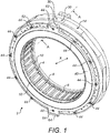
Figure 1 shows a stator assembly in accordance with the disclosure; -
Figure 2 shows an exploded view of the stator assembly ofFigure 1 ; -
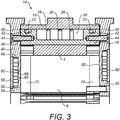
Figure 3 shows a cross-section of the stator assembly ofFigure 1 , taken along the line A-A; -
Figure 4 shows a detail of a further embodiment of a cooling plate usable in the stator assembly ofFigure 1 ; and -
Figure 5 shows a detail of a second embodiment of cooling plate usable in the state assembly ofFigure 1 . - With reference to
figures 1 and2 , astator 2 of an electrical machine is illustrated. In this embodiment, the machine is an electric motor. However, the principles of the disclosure may be applied to other electrical machines, for example generators. - The
stator 2 comprises an annular core 4 which extends around a stator axis X. The core 4 comprises a plurality of axially extendingslots 6 which receivewindings 8. In this embodiment, theslots 6 extend parallel to the axis X, but in other embodiments, they may be angled relative thereto. - The
windings 8 haveend portions 10 at the axial ends 12 of the core 4 which pass betweenadjacent core slots 6. - The core 4 may be made as a unitary body or in one or more parts which are assembled together to form the core 4. Such an arrangement is illustrated in
Figure 2 . - The core 4 is surrounded on a radially
outer surface 13 by anannular cooling jacket 14. Thecooling jacket 14 comprises an annular radiallyinner part 16 and an annular radiallyouter cover part 18 which define one or morecoolant passages 20 therebetween for receiving a coolant. In an exemplary embodiment, thecoolant passage 20 may be anannular coolant passage 20. The coolant may be a gaseous coolant such as air, but advantageously it may be a liquid coolant to improve heat transfer. A typical coolant may be water or water/glycol mixture. - As illustrated in
Figure 3 , seals 22 such as O-ring seals 22 may be provided at opposed axial ends of thejacket 14 to prevent leakage of coolant from thecoolant passage 20. The radiallyinner part 16 and radiallyouter part 18 of thejacket 14 may be secured together in any suitable manner, for example, through fasteners, welding or brazing. - The core 4 may be mounted to the radially
inner part 16 of thewater jacket 14 by any suitable means. For example, keys (not shown) may be used radially to locate the core 4 in the coolingjacket 14 andaxial plates 24 locate the core 4 axially. However, this is just one possibility and the skilled person will recognise other mechanisms by which the core 4 can be mounted in the coolingjacket 14. - The cooling
jacket 14 may, as shown, be formed with heat transfer enhancement features 26, to enhance heat transfer from the core 4 andwindings 8 into the coolant. In this embodiment the heat transfer enhancement features 26 comprise a plurality of circumferentially extendingribs 28. However, other forms of heat transfer enhancement features 26 may be used, for example pin fins having a cross-sectional shape including, but not limited to, circular, square, rectangular, diamond, oval, or teardrop shapes. While heat transfer enhancement features 26 have been shown on the radiallyinner part 16 of the coolingjacket 14,such features 26 may be provided either alternatively or additionally on the radiallyouter part 18 of thejacket 14. - As illustrated in
Figure 1 , the coolingjacket 14 may have one ormore inlets 30 for admitting cooling fluid into thecooling passage 20. One or more outlets (not shown) for the cooling fluid may also be provided, for example diametrically opposite theinlets 30. - While the cooling
jacket 14 provides some cooling to the core 4 andwindings 8, additional cooling is provided by a pair of coolingplates 40 arranged at opposed axial ends 12 of the core 4. - The cooling
plates 40 are mounted to respective axial ends 42 of the coolingjacket 14. In this embodiment, the coolingplates 40 are removably mounted to thejacket 14. This will allow thecooling plates 40 to be removed for maintenance or replacement purposes. - The cooling
jacket 14 provides a robust support for thecooling plates 40 and provides a potential heat flow path from the coolingplates 40. - The cooling
plates 40 may be directly mounted to the axial ends of the cooling jacket or via an intermediate component - As shown, the cooling
plates 40 may be mounted to the coolingjacket 14 by means of bolts or other threadedfasteners 44 passing throughbores 46 in thecooling plates 40 into threaded openings 48 formed in the respective end faces 50 of the coolingjacket 14. As can be seen inFigure 1 for example, a plurality ofbolts 44 may be spaced around the external periphery of the coolingplate 40. Thebores 46 may be formed inlugs 52 projecting radially from the coolingplates 40. - In as illustrated in this embodiment, the cooling
plate 40 may comprise abase element 54 having anannular groove 56 which is closed by acover plate 58. Thebase element 54 andcover plate 58 thereby define one ormore cooling passages 60 through the coolingplate 40 for receiving a cooling fluid. The cooling fluid may be a gaseous coolant but advantageously it may be a liquid coolant to improve heat transfer. A typical coolant may be water or water/glycol mix. - The
cooling passage 60 may be a continuousannular passage 60. In alternative embodiments, a plurality of annular passages may be formed. The skilled person will be able to envisage various arrangements ofcooling passages 60 within the coolingplates 40. - One or more cooling
fluid inlets 62 and one or more coolingfluid outlets 64 may be provided on each coolingplate 40. As illustrated, the coolingfluid inlets 62 and coolingfluid outlets 64 may be arranged on diametrically opposed sections of the coolingplate 40. The coolingfluid inlets 62 and coolingfluid outlets 64 may be circumferentially aligned with each other and with the coolingfluid inlets 30 and cooling fluid outlets of the coolingjacket 14 for ease of connection of coolant. - The
cover plate 58 may be mounted to thebase element 54 in any suitable manner. For example, thecover plate 58 may be welded or brazed to thebase element 54. To facilitate positioning, thecover plate 58 may be received on arecess 66 formed around thegroove 56. If necessary, a seal element (not shown) may be provided between thecover plate 58 and thebase element 54. - In a manner similar to the cooling
jacket 14, the at least onecooling passage 60 of the coolingplate 40 may comprise heat transfer enhancement features 68 to enhance heat transfer from the core 4 andwindings 8 into the coolant circulating through the coolingplate 40. The heat transfer enhancement features 68 extend across thecooling passage 60, in this case completely across thecooling passage 60 so as to extend between thebase element 54 and the cover 88. In other embodiments, however, the heat transfer enhancement features 68 need not extend completely across thecooling passage 60. - As shown in
Figure 4 , in one embodiment the heat transfer enhancement features 68 may comprise a plurality of circumferentially extendingribs 70. The particular arrangement of theribs 70 can be chosen by the skilled person to provide the necessary cooling requirements. - In another embodiment, illustrated in
Figure 5 , the heat transfer enhancement features 68 are in the form ofpin fins 72. Thepin fins 72 may have a circular cross-sectional shape as illustrated. However, thepin fins 72 may have other cross-sectional shape such as square, rectangular, diamond-shaped, oval or teardrop shaped. Again the particular arrangement of thepin fins 72 can be chosen by the skilled person to provide the necessary cooling requirements. - Of course other configurations of heat transfer enhancement features 68 may be envisaged, for example a combination of
ribs 70 andpin fins 72. - The heat transfer enhancement features 68 have been shown in the illustrated embodiment as being formed in the
base element 64. They could, for example, be machined into thebase element 64. In other embodiments, heat transfer enhancement features 68 may be provided either alternatively or additionally on thecover plate 58. - As can be seen from
Figure 3 , the coolingplates 40 are arranged in thermal contact with theend portions 10 of thewindings 8. In particular, the coolingplates 40 are arranged in thermal contact with axially outwardly facing end surfaces 80 of theend portions 10 of thewindings 8. The coolingplates 40 may directly contact the end portions of thewindings 8 as shown such that there is direct thermal contact therebetween. In other embodiments, however, a heat transfer medium may be provided between the coolingplates 40 and thewindings 8. - To improve thermal contact, the end surfaces 80 of the
end portions 10 of thewindings 8 may be shaped so as to be complementary to theopposite surfaces 82 of the coolingplates 40. For example, as shown in this embodiment, the end surfaces 80 of theend portions 10 of thewindings 8 may be flat such that there is a planar engagement with theopposite surfaces 82 of the coolingplates 40. As will be described further below, this may be achieved during assembly of the coolingplates 40 to thestator 2. - The cooling
plates 40 may be manufactured from a material having good thermal conductivity. Thus, for example, the coolingplates 40 may be manufactured from aluminium or aluminium alloys in certain embodiments. - Having described the structure of the
stator 2, its assembly will now be described. - As a first step, the core 4 may be assembled into the cooling
jacket 14. As discussed above, the core 4 may be retained in the coolingjacket 14 by various suitable means. The core 4 may advantageously be wound with itswindings 8 prior to assembly into the coolingjacket 14. The coolingjacket 14 may be preassembled prior to fitting of the core 4, allowing it to be tested for leakage etc. prior to assembly. - The cooling
plates 40 may then be attached to the opposed axial ends 42 of the coolingjacket 14. - In an advantageous embodiment, the cooling
plates 40 are preassembled into respective units prior to fitting to the coolingjacket 14. Thus, thecover plate 58 may be mounted over and close thegroove 56 in thebase element 54 and secured in place. This will allow thecooling plates 40 to be tested, for example for leakages prior to assembly into the coolingjacket 14, for example by a supplier. - The cooling
plates 40 are attached to the coolingjacket 14 by thefasteners 44. The coolingplates 40 contact the end surfaces 80 of theend portions 10 of thewindings 8 during assembly. Tightening of the coolingplates 40 against the coolingjacket 14 may act to deform the end surfaces 80 into conformity with the contour of theinner surface 82 of the coolingplate 40 in order to improve heat transfer therebetween. Of course the axially facing end surfaces 80 may be curved, without flat regions. - Once assembled, the
stator 2 may be tested electrically and hydraulically prior to its assembly into a machine. This means that only one fully tested component need to be assembled to the machine instead of multiple components requiring individual testing. This represents a significant time-saving during production. - Should it become necessary to repair or maintain the
stator 2, the coolingplates 40 may be removed from the coolingjacket 14 for maintenance and also to provide access to the core 4 andwindings 8. If necessary the coolingplates 40 may be replaced. This is easily achieved due to the modular nature of the design. - It will be seen from the above that the disclosure provides a stator construction which provides improved cooling by means of cooling plates mounted to a cooling jacket and in close thermal contact with end portions of the stator winding. The modular nature of the construction allows its easy assembly and, if necessary, pretesting of system components prior to assembly. It also allows for easy removal of any faulty component without the need to scrap an entire assembly.
- It will be understood that the embodiment disclosed is merely exemplary and that modifications may be made to it without departing from the scope of the disclosure.
- Thus, for example, while the cooling
plates 40 have been described as being made from two parts assembled together to define a cooling passage, the cooling passage could be formed in some other way. For example, the cooling passage may be formed e.g. cast into a unitary plate structure, or may be made by additive manufacturing. Also, the particular shape and configuration of the cooling passage may vary from embodiment to embodiment. - Also, while the cooling
plates 40 have been described as being mounted to the coolingjacket 14, they may be mounted to some other structure of thestator assembly 2 such as a housing, for example if a cooling jacket is not present. However, as mentioned above, mounting to a coolingjacket 14 is advantageous in that the coolingjacket 14 provides a robust mounting location for the coolingplate 40 as well as potentially allowing for heat transfer from the coolingplate 40.
Claims (15)
- A stator assembly (2) for an electrical machine, the stator assembly (2) comprising:an annular core (4) extending around an axis (X) and comprising a plurality of axially extending slots (6);a plurality of electrical windings (8) arranged in the slots (8) and having end portions (10) arranged at the axial ends (12) of the core (4); andat least one annular cooling plate (40) mounted at an axial end (12) of the core (4) and arranged in thermal contact with axially outwardly facing end surfaces (80) of the end portions (10) of the electrical windings (8).
- The stator assembly of claim 1, further comprising a cooling jacket (14) at least partially extending around a radially outer surface (13) of the core (4), the at least one annular cooling plate (40) being mounted to an axial end (42) of the cooling jacket
- The stator assembly of claim 1 or 2, comprising a respective cooling plate (40) provided at each axial end of the stator (2).
- The stator assembly of any preceding claim, wherein the at least one cooling plate (40) is arranged in direct thermal contact with the end portions (10) of the electrical windings (8).
- The stator assembly of any preceding claim, wherein the at least one cooling plate (40) comprises a cooling passage (60) configured to carry a cooling fluid.
- The stator assembly of claim 5, wherein the at least one cooling plate (40) comprises a base element (54) defining a groove (56) and a cover (58) attached to the base element (54) for closing the groove (56) to form the cooling passage (60).
- The stator assembly of claim 5 or 6, wherein the at least one cooling plate (40) comprises heat transfer enhancement features (68) which extend into the cooling passage (60), optionally extending completely across the cooling passage (60).
- The stator assembly of claim 7, wherein the heat transfer enhancement features (68) comprise ribs (70) and/or pin fins (72), wherein optionally the pin fins (72) comprise a square, rectangular, diamond shaped, oval or teardrop cross-section.
- The stator assembly of any of claims 5 to 8, wherein the at least one cooling plate (40) comprises at least one cooling fluid inlet (62) and at least one cooling fluid outlet (64), and wherein, optionally, the at least one fluid inlet (62) is located on a diametrically opposite side of the at least one cooling plate (40) from the at least one fluid outlet (64).
- The stator assembly of any preceding claim, wherein the at least one cooling plate (40) is formed from aluminium.
- The stator assembly of any preceding claim, wherein the at least one cooling plate (40) is removably mounted stator assembly, for example to the cooling jacket (14), for example via a fastener (44) for example a threaded fastener (44).
- A method of assembling a stator assembly (2) for an electrical machine, the stator assembly (2) comprising an annular core (4) extending around an axis (X) and comprising a plurality of axially extending slots (6); and a plurality of electrical windings (8) arranged in the slots (6) and having end portions (8) at axial ends of the core (4);; the method comprising:
mounting at least one annular cooling plate (40) at an axial end (12) of the core (4) and in thermal contact with axially facing surfaces of the end portions (10) of the electrical windings (8). - The method of claim 12, wherein attaching the at least one cooling plate (40) at an axial end (12) of the core (4) comprises mounting the cooling plate (40) to a cooling jacket (14) which at least partially extends around a radially outer surface (13) of the core (4), optionally removably attaching the cooling plate (40) to the cooling jacket (14) for example using threaded fasteners (44).
- The method of claim 12 or 13, further comprising leak testing and/or electrically testing the assembled stator assembly (2) after attaching the at least one cooling plate (40) to the stator assembly (2).
- The method of any of claims 12 to 14, further comprising removing the at least one cooling plate (40) to carry out maintenance on the stator assembly (2).
Priority Applications (2)
| Application Number | Priority Date | Filing Date | Title |
|---|---|---|---|
| EP19275117.0A EP3820026A1 (en) | 2019-11-05 | 2019-11-05 | Electrical machines |
| US17/088,832 US11664689B2 (en) | 2019-11-05 | 2020-11-04 | Electrical machines |
Applications Claiming Priority (1)
| Application Number | Priority Date | Filing Date | Title |
|---|---|---|---|
| EP19275117.0A EP3820026A1 (en) | 2019-11-05 | 2019-11-05 | Electrical machines |
Publications (1)
| Publication Number | Publication Date |
|---|---|
| EP3820026A1 true EP3820026A1 (en) | 2021-05-12 |
Family
ID=68470448
Family Applications (1)
| Application Number | Title | Priority Date | Filing Date |
|---|---|---|---|
| EP19275117.0A Pending EP3820026A1 (en) | 2019-11-05 | 2019-11-05 | Electrical machines |
Country Status (2)
| Country | Link |
|---|---|
| US (1) | US11664689B2 (en) |
| EP (1) | EP3820026A1 (en) |
Families Citing this family (2)
| Publication number | Priority date | Publication date | Assignee | Title |
|---|---|---|---|---|
| US11962188B2 (en) * | 2021-01-21 | 2024-04-16 | General Electric Company | Electric machine |
| US20260005559A1 (en) * | 2024-07-01 | 2026-01-01 | Hamilton Sundstrand Corporation | Thermal management of an electric motor |
Citations (6)
| Publication number | Priority date | Publication date | Assignee | Title |
|---|---|---|---|---|
| US20100126703A1 (en) * | 2008-09-16 | 2010-05-27 | Joy Ride Tech. Co., Ltd. | Motor device with heat dissipating capability |
| US8093770B1 (en) | 2010-09-15 | 2012-01-10 | Ford Global Technologies, Llc | Electric motor with liquid-cooled end windings |
| WO2012154423A2 (en) * | 2011-05-10 | 2012-11-15 | Remy Technologies, Llc | Cooling combinations for electric machines |
| EP3163717A1 (en) * | 2014-06-24 | 2017-05-03 | Kubota Corporation | Stator of electric motor and cooling structure for dynamo-electric machine |
| US20180174098A1 (en) * | 2015-04-02 | 2018-06-21 | Hamilton Sundstrand Corporation | Stator heat transfer feature for a dynamoelectric machine |
| CN207968165U (en) * | 2018-04-12 | 2018-10-12 | 核心驱动科技(金华)有限公司 | A kind of heat-dissipation motor end cap and synchronous motor |
Family Cites Families (9)
| Publication number | Priority date | Publication date | Assignee | Title |
|---|---|---|---|---|
| DE102004048461A1 (en) | 2004-10-05 | 2006-04-27 | Siemens Ag | Housing for an electrical machine |
| DE102006022139A1 (en) | 2006-05-11 | 2007-11-15 | Siemens Ag | Device for cooling an electric machine and electric machine with such a cooling device |
| US8519582B2 (en) | 2009-09-29 | 2013-08-27 | Regal Beloit America, Inc. | Air cooled electric motor |
| US8378550B2 (en) * | 2010-09-10 | 2013-02-19 | Remy Technologies, L.L.C. | Electric machine including a stator having a stator sleeve and method of cooling a stator |
| US8970073B2 (en) * | 2010-10-19 | 2015-03-03 | Toyota Jidosha Kabushiki Kaisha | Cooling structure for rotary electric machine |
| JP5942714B2 (en) * | 2012-09-07 | 2016-06-29 | 株式会社デンソー | Rotating electric machine |
| US10536055B2 (en) * | 2016-03-17 | 2020-01-14 | Ford Global Technologies, Llc | Thermal management assembly for an electrified vehicle |
| CN109560656A (en) * | 2018-11-21 | 2019-04-02 | 中国科学院电工研究所 | A kind of connection type in reliable motor cycle water route |
| CN109617272B (en) * | 2019-01-03 | 2020-02-21 | 江麓机电集团有限公司 | Integrated form cooling structure based on electric drive system |
-
2019
- 2019-11-05 EP EP19275117.0A patent/EP3820026A1/en active Pending
-
2020
- 2020-11-04 US US17/088,832 patent/US11664689B2/en active Active
Patent Citations (6)
| Publication number | Priority date | Publication date | Assignee | Title |
|---|---|---|---|---|
| US20100126703A1 (en) * | 2008-09-16 | 2010-05-27 | Joy Ride Tech. Co., Ltd. | Motor device with heat dissipating capability |
| US8093770B1 (en) | 2010-09-15 | 2012-01-10 | Ford Global Technologies, Llc | Electric motor with liquid-cooled end windings |
| WO2012154423A2 (en) * | 2011-05-10 | 2012-11-15 | Remy Technologies, Llc | Cooling combinations for electric machines |
| EP3163717A1 (en) * | 2014-06-24 | 2017-05-03 | Kubota Corporation | Stator of electric motor and cooling structure for dynamo-electric machine |
| US20180174098A1 (en) * | 2015-04-02 | 2018-06-21 | Hamilton Sundstrand Corporation | Stator heat transfer feature for a dynamoelectric machine |
| CN207968165U (en) * | 2018-04-12 | 2018-10-12 | 核心驱动科技(金华)有限公司 | A kind of heat-dissipation motor end cap and synchronous motor |
Also Published As
| Publication number | Publication date |
|---|---|
| US20210135516A1 (en) | 2021-05-06 |
| US11664689B2 (en) | 2023-05-30 |
Similar Documents
| Publication | Publication Date | Title |
|---|---|---|
| US2338154A (en) | Fluid-cooled dynamoelectric machine | |
| JP2019161752A (en) | Rotary electric machine stator | |
| HK1255433A1 (en) | Cast cooling arrangement for electric machines | |
| KR20130110142A (en) | Electric machine cooling system and method | |
| US11664689B2 (en) | Electrical machines | |
| US20150229186A1 (en) | Axial induction machine | |
| US20200328641A1 (en) | Rotor for an electric machine | |
| EP4542829A1 (en) | Electric drive system shell for vehicle and vehicle | |
| EP4407849B1 (en) | Axial flux motor, electric device, and vehicle | |
| CN117353481A (en) | Stator punching sheets, motors, powertrains and electric vehicles with circumferential flow channels | |
| KR20130032828A (en) | Electric machine module cooling system and method | |
| CN114977555A (en) | Stator module and motor | |
| KR20220127556A (en) | Motor and motor cooling system | |
| KR20130123317A (en) | Electric machine module cooling system and method | |
| EP4087092B1 (en) | Motor cooling system, motor stator and disc motor | |
| CN222234504U (en) | Stator of axial flux motor and axial flux motor | |
| CN112886735A (en) | Motor stator assembly with cooling flow channel | |
| JP2012223003A (en) | Hybrid construction machine | |
| EP4187758B1 (en) | Stator for electrical machines | |
| KR20100077427A (en) | Rotating apparatus | |
| CN221305644U (en) | Cooling structure, motor, air compressor, fuel cell engine and vehicle | |
| CN114123611A (en) | Cooling jacket, shell assembly and motor | |
| CN112104141A (en) | Cooling jacket, motor and vehicle | |
| CN220915025U (en) | Rotor disc | |
| CN220172944U (en) | Oil-cooled driving motor rotor, oil-cooled driving motor and vehicle |
Legal Events
| Date | Code | Title | Description |
|---|---|---|---|
| PUAI | Public reference made under article 153(3) epc to a published international application that has entered the european phase |
Free format text: ORIGINAL CODE: 0009012 |
|
| STAA | Information on the status of an ep patent application or granted ep patent |
Free format text: STATUS: THE APPLICATION HAS BEEN PUBLISHED |
|
| AK | Designated contracting states |
Kind code of ref document: A1 Designated state(s): AL AT BE BG CH CY CZ DE DK EE ES FI FR GB GR HR HU IE IS IT LI LT LU LV MC MK MT NL NO PL PT RO RS SE SI SK SM TR |
|
| STAA | Information on the status of an ep patent application or granted ep patent |
Free format text: STATUS: REQUEST FOR EXAMINATION WAS MADE |
|
| 17P | Request for examination filed |
Effective date: 20211112 |
|
| RBV | Designated contracting states (corrected) |
Designated state(s): AL AT BE BG CH CY CZ DE DK EE ES FI FR GB GR HR HU IE IS IT LI LT LU LV MC MK MT NL NO PL PT RO RS SE SI SK SM TR |
|
| STAA | Information on the status of an ep patent application or granted ep patent |
Free format text: STATUS: EXAMINATION IS IN PROGRESS |
|
| 17Q | First examination report despatched |
Effective date: 20240517 |
|
| GRAP | Despatch of communication of intention to grant a patent |
Free format text: ORIGINAL CODE: EPIDOSNIGR1 |
|
| STAA | Information on the status of an ep patent application or granted ep patent |
Free format text: STATUS: GRANT OF PATENT IS INTENDED |
|
| GRAJ | Information related to disapproval of communication of intention to grant by the applicant or resumption of examination proceedings by the epo deleted |
Free format text: ORIGINAL CODE: EPIDOSDIGR1 |
|
| STAA | Information on the status of an ep patent application or granted ep patent |
Free format text: STATUS: EXAMINATION IS IN PROGRESS |
|
| INTG | Intention to grant announced |
Effective date: 20260305 |
|
| GRAP | Despatch of communication of intention to grant a patent |
Free format text: ORIGINAL CODE: EPIDOSNIGR1 |
|
| STAA | Information on the status of an ep patent application or granted ep patent |
Free format text: STATUS: GRANT OF PATENT IS INTENDED |
|
| INTC | Intention to grant announced (deleted) |