EP3820010A1 - Power supply assembly with reactive power compensation - Google Patents
Power supply assembly with reactive power compensation Download PDFInfo
- Publication number
- EP3820010A1 EP3820010A1 EP19207622.2A EP19207622A EP3820010A1 EP 3820010 A1 EP3820010 A1 EP 3820010A1 EP 19207622 A EP19207622 A EP 19207622A EP 3820010 A1 EP3820010 A1 EP 3820010A1
- Authority
- EP
- European Patent Office
- Prior art keywords
- power supply
- supply assembly
- connection
- alternating current
- converter
- Prior art date
- Legal status (The legal status is an assumption and is not a legal conclusion. Google has not performed a legal analysis and makes no representation as to the accuracy of the status listed.)
- Pending
Links
Images

Classifications
-
- H—ELECTRICITY
- H02—GENERATION; CONVERSION OR DISTRIBUTION OF ELECTRIC POWER
- H02J—ELECTRIC POWER NETWORKS; CIRCUIT ARRANGEMENTS OR SYSTEMS FOR SUPPLYING OR DISTRIBUTING ELECTRIC POWER; SYSTEMS FOR STORING ELECTRIC ENERGY
- H02J3/00—Circuit arrangements for AC mains or AC distribution networks
- H02J3/18—Arrangements for adjusting, eliminating or compensating reactive power in networks
- H02J3/1821—Arrangements for adjusting, eliminating or compensating reactive power in networks using shunt compensators
- H02J3/1835—Arrangements for adjusting, eliminating or compensating reactive power in networks using shunt compensators with stepless control
-
- H—ELECTRICITY
- H02—GENERATION; CONVERSION OR DISTRIBUTION OF ELECTRIC POWER
- H02J—ELECTRIC POWER NETWORKS; CIRCUIT ARRANGEMENTS OR SYSTEMS FOR SUPPLYING OR DISTRIBUTING ELECTRIC POWER; SYSTEMS FOR STORING ELECTRIC ENERGY
- H02J3/00—Circuit arrangements for AC mains or AC distribution networks
- H02J3/12—Arrangements for adjusting voltage in AC networks by changing a characteristic of the network load
- H02J3/16—Arrangements for adjusting voltage in AC networks by changing a characteristic of the network load by adjustment of reactive power
-
- H—ELECTRICITY
- H02—GENERATION; CONVERSION OR DISTRIBUTION OF ELECTRIC POWER
- H02J—ELECTRIC POWER NETWORKS; CIRCUIT ARRANGEMENTS OR SYSTEMS FOR SUPPLYING OR DISTRIBUTING ELECTRIC POWER; SYSTEMS FOR STORING ELECTRIC ENERGY
- H02J3/00—Circuit arrangements for AC mains or AC distribution networks
- H02J3/17—Demand-responsive operation of AC power transmission or distribution networks
-
- H—ELECTRICITY
- H02—GENERATION; CONVERSION OR DISTRIBUTION OF ELECTRIC POWER
- H02J—ELECTRIC POWER NETWORKS; CIRCUIT ARRANGEMENTS OR SYSTEMS FOR SUPPLYING OR DISTRIBUTING ELECTRIC POWER; SYSTEMS FOR STORING ELECTRIC ENERGY
- H02J9/00—Circuit arrangements for emergency or stand-by power supply, e.g. for emergency lighting
- H02J9/04—Circuit arrangements for emergency or stand-by power supply, e.g. for emergency lighting in which the distribution system is disconnected from the normal source and connected to a standby source
- H02J9/06—Circuit arrangements for emergency or stand-by power supply, e.g. for emergency lighting in which the distribution system is disconnected from the normal source and connected to a standby source with automatic change-over, e.g. UPS systems
- H02J9/062—Circuit arrangements for emergency or stand-by power supply, e.g. for emergency lighting in which the distribution system is disconnected from the normal source and connected to a standby source with automatic change-over, e.g. UPS systems for AC powered loads
-
- Y—GENERAL TAGGING OF NEW TECHNOLOGICAL DEVELOPMENTS; GENERAL TAGGING OF CROSS-SECTIONAL TECHNOLOGIES SPANNING OVER SEVERAL SECTIONS OF THE IPC; TECHNICAL SUBJECTS COVERED BY FORMER USPC CROSS-REFERENCE ART COLLECTIONS [XRACs] AND DIGESTS
- Y02—TECHNOLOGIES OR APPLICATIONS FOR MITIGATION OR ADAPTATION AGAINST CLIMATE CHANGE
- Y02B—CLIMATE CHANGE MITIGATION TECHNOLOGIES RELATED TO BUILDINGS, e.g. HOUSING, HOUSE APPLIANCES OR RELATED END-USER APPLICATIONS
- Y02B70/00—Technologies for an efficient end-user side electric power management and consumption
- Y02B70/30—Systems integrating technologies related to power network operation and communication or information technologies for improving the carbon footprint of the management of residential or tertiary loads, i.e. smart grids as climate change mitigation technology in the buildings sector, including also the last stages of power distribution and the control, monitoring or operating management systems at local level
-
- Y—GENERAL TAGGING OF NEW TECHNOLOGICAL DEVELOPMENTS; GENERAL TAGGING OF CROSS-SECTIONAL TECHNOLOGIES SPANNING OVER SEVERAL SECTIONS OF THE IPC; TECHNICAL SUBJECTS COVERED BY FORMER USPC CROSS-REFERENCE ART COLLECTIONS [XRACs] AND DIGESTS
- Y04—INFORMATION OR COMMUNICATION TECHNOLOGIES HAVING AN IMPACT ON OTHER TECHNOLOGY AREAS
- Y04S—SYSTEMS INTEGRATING TECHNOLOGIES RELATED TO POWER NETWORK OPERATION, COMMUNICATION OR INFORMATION TECHNOLOGIES FOR IMPROVING THE ELECTRICAL POWER GENERATION, TRANSMISSION, DISTRIBUTION, MANAGEMENT OR USAGE, i.e. SMART GRIDS
- Y04S20/00—Management or operation of end-user stationary applications or the last stages of power distribution; Controlling, monitoring or operating thereof
- Y04S20/20—End-user application control systems
Definitions
- the present invention relates to a power supply assembly.
- the objects of the invention are achieved by a power supply assembly which is characterized by what is stated in the independent claim.
- the preferred embodiments of the invention are disclosed in the dependent claims.
- the invention is based on the realization that in some operating situations, depending on a power supply assembly and load thereof, it is possible to improve total efficiency of the power supply assembly by increasing a number of converters used for reactive power compensation.
- the improvement of the total efficiency of the power supply assembly is achieved by selecting a combination of converters used for reactive power compensation such that each of the converters operates in a predetermined optimal efficiency range thereof.
- the power supply assembly according to present invention is part of an uninterruptible power supply system.
- an operative mode in which an efficiency optimization operation is used is sometimes called an energy saver mode.
- energy saver mode energy is transferred from a primary source connection to a load connection such that the energy flow bypasses converters of the power supply assembly.
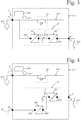
- Figure 1 shows a simplified circuit diagram of a power supply assembly 101 comprising a source connection system 4, a load connection system 7, a converter system comprising a plurality of converter modules 8, an energy saving transfer route 457, a power determining system 947 and a control system 909.
- the source connection system 4 comprises two alternating current connections, and one direct current connection.
- One of the alternating current connections of the source connection system 4 is a primary source connection 41 adapted to be connected to a primary alternating current supply 301.
- the other of the alternating current connections of the source connection system 4 is a secondary source connection 42 adapted to be connected to a secondary alternating current supply 302.
- the direct current connection of the source connection system 4 is denoted with reference number 43, and is adapted to be connected to a direct current supply 461.
- the source connection system comprises at least one alternating current connection, and optionally a direct current connection.
- the load connection system 7 comprises a load connection 71 adapted to be connected to a load 707.
- the load 707 is an alternating current load.
- the converter modules 8 of the converter system are connected in parallel, and are identical with each other. For sake of clarity, only one of the converter modules 8 is depicted.
- the converter system comprises at least one converter controllable for reactive power compensation, and connected electrically to at least one alternating current connection of the source connection system through an alternating current connection of the converter.
- the converter module 8 comprises a rectifier 81, a DC link 2, an inverter 82, and a direct-current converter 84.
- the rectifier 81 is connected electrically to the secondary source connection 42 through an alternating current connection 811 thereof.
- the inverter 82 is connected electrically to the energy saving transfer route 457 through an alternating current connection 822 thereof.
- the rectifiers 81 and the inverters 82 are functionally identical converter units with each other.
- Each rectifier 81 and each inverter 82 is a bidirectional converter adapted to transfer energy both from the alternating current connection thereof, and into the alternating current connection thereof.
- the DC link 2 comprises DC link capacitance, and connects electrically the rectifier 81 to the inverter 82.
- the DC link 2 is connected to a direct current connection 812 of the rectifier 81, and to a direct current connection 821 of the inverter 82.
- the rectifier 81 and the inverter 82 are controllable for reactive power compensation.
- the energy saving transfer route 457 connects the primary source connection 41 electrically to the load connection 71, and bypasses the converter system.
- the inverter 82 is connected electrically to the energy saving transfer route 457 through an alternating current connection 822 thereof. Therefore, the inverter 82 can be used for compensating reactive power passing through the primary source connection 41.
- the rectifier 81 is connected electrically to the secondary source connection 42 through an alternating current connection 811 thereof. Therefore, the rectifier 81 can be used for compensating reactive power passing through the secondary source connection 42.
- the energy saving transfer route 457 comprises a bypass switch 52 adapted to disconnect the primary source connection 41 from the load connection 71.
- the bypass switch 52 is controllable by the control system 909.
- the bypass switch 52 comprises a mechanical switch and a thyristor connected in parallel.
- the bypass switch is a bidirectional semiconductor device comprising two controllable semiconductor switches connected antiparallel with each other.
- the bypass switch comprises two controllable semiconductor switches connected antiparallel with each other, and a mechanical switch connected in parallel with the controllable semiconductor switches.
- the controllable semiconductor switch may be a field-effect transistor or an insulated-gate bipolar transistor, for example.
- the power supply assembly 101 comprises only one bypass switch 52 which is common for the plurality of converter modules 8.
- the power supply assembly comprises a bypass switch system having a bypass switch for each converter module.
- the power determining system 947 is adapted for determining power supplied into the power supply assembly 101 through the source connection system 4, and power supplied out of the power supply assembly 101 through the load connection system 7.
- the control system 909 is adapted to control the converter system and the bypass switch 52.
- the control system 909 is adapted to provide an efficiency optimization operation comprising transferring energy from the primary source connection 41 to the load connection 71 through the energy saving transfer route 457, determining for the power supply assembly 101 an optimal operating scheme that optimizes coefficient of efficiency of the power supply assembly 101 while keeping reactive power drawn from the source connection system 4 within a required range, wherein the optimal operating scheme defines an optimal combination for the converters used for reactive power compensation such that each of the converters operates in a predetermined optimal efficiency range thereof, and controlling the converter system according to the optimal operating scheme. Said optimal combination for the converters used for reactive power compensation changes as a load of the power supply assembly changes.
- controlling the converter system according to the optimal operating scheme comprises hysteresis between transitions from one combination for the converters to another combination.
- hysteresis means that the optimal operating scheme comprises discrete steps overlapping each other in order to reduce number of changes between different combinations for the converters in situations where electric current at the load connection fluctuates at a boundary between two different optimal combinations for the converters.
- Keeping reactive power drawn from the source connection system within a required range means that reactive current at alternating current connection(s) of the source connection system is kept lower than or equal to a predetermined reactive current value, and/or power factor is controlled such that it is greater than or equal to a predetermined power factor. In other words, in some embodiments it is not intention to compensate reactive power completely. Further, it can be said that the efficiency optimization operation optimizes coefficient of efficiency of the power supply assembly using boundary conditions relating to required level of reactive power compensation.
- selecting an optimal combination for the converters used for reactive power compensation comprises not only selecting a number of the converters but also takes into account a source connection to which each converter is connected through an alternating current connection thereof, as well as electrical characteristics of each converter.
- only the inverters 82 can be used for compensating reactive power passing through the primary source connection 41, and only the rectifiers 81 can be used for compensating reactive power passing through the secondary source connection 42.
- a coefficient of efficiency of a power supply assembly is a quotient of an active power supplied out of the power supply assembly through the load connection system, and an active power supplied into the power supply assembly through the source connection system.
- the coefficient of efficiency takes into account power required for operating converters of the power supply assembly.
- the converters used for reactive power compensation only supply reactive power, and no active power.
- a reactive power passing through an alternating current connection of the converter is at least 95 % of an apparent power passing through the alternating current connection.
- Figure 2 shows an efficiency curve of an inverter 82 of the power supply assembly shown in Figure 1 . Since the rectifiers 81 and the inverters 82 are identical converter units with each other, Figure 2 also shows an efficiency curve of a rectifier 81 of the power supply assembly shown in Figure 1 .
- the efficiency curve Figure 2 has an optimal efficiency operating point 181 that is included in a predetermined optimal efficiency range 898 of the converter.
- a width of the predetermined optimal efficiency range 898 is approximately 20 % of a nominal current of the converter. In alternative embodiments, a width of the predetermined optimal efficiency range is in a range of 5 - 40 % of a nominal current of the converter.
- the optimal operating scheme defines an optimal reactive power compensation for each converter used for the reactive power compensation.
- rectifiers 81 and inverters 82 of the converter modules 8 are available for reactive power compensation.
- the control system 909 decides which rectifiers 81 and which inverters 82 are used for the reactive power compensation while the rest of rectifiers 81 and inverters 82 are kept currentless such that there is no electric current flowing in or out through their alternating current connections.
- each of the converters used for the reactive power compensation operates at the optimal efficiency operating point 181 thereof.
- each rectifier 81 and each inverter 82 either operates at the optimal efficiency operating point 181 thereof, or is kept currentless.
- the control system 909 is adapted to calculate the optimal operating scheme based on initial data comprising information relating to power supplied out of the power supply assembly 101 through the load connection system 7, and information relating to electrical properties of components of the power supply assembly 101.
- the initial data comprises data received from the power determining system 947.
- control system is adapted to calculate the optimal operating scheme based on initial data comprising information relating to power supplied into the power supply assembly through the source connection system and/or power supplied out of the power supply assembly through the load connection system, and information relating to electrical properties of components of the power supply assembly.
- control system utilizes for the determining of the optimal operating scheme at least one table comprising information relating to optimal operating schemes for different load situations of the power supply assembly. Use of precalculated tables reduces computing capacity required of the control system.
- FIG 3 shows a simplified circuit diagram of a power supply assembly 101' according to another embodiment of the invention.
- the power supply assembly 101' is a modification of the power supply assembly 101 shown in Figure 1 .
- the power supply assembly 101' comprises a source connection system 4', a load connection system 7', a converter system comprising a plurality of converter modules 8', an energy saving transfer route 457', a power determining system 947' and a control system 909'.
- the source connection system 4' of the power supply assembly 101' comprises one alternating current connection, and no direct current connections.
- the alternating current connection of the source connection system 4' is a primary source connection 41' adapted to be connected to a primary alternating current supply 301'.
- the converter module 8' comprises a rectifier 81', a DC link 2', and an inverter 82'.
- the rectifier 81' is connected electrically to the energy saving transfer route 457', on one side of a bypass switch 52', through an alternating current connection 811' of the rectifier 81'.
- the inverter 82' is connected electrically to the energy saving transfer route 457', on the other side of the bypass switch 52', through an alternating current connection 822' of the inverter 82'. Both the rectifier 81' and the inverter 82' can be used for compensating reactive power passing through the primary source connection 41'.
- FIG 4 shows a simplified circuit diagram of a power supply assembly 101" according to yet another embodiment of the invention.
- the power supply assembly 101" is a modification of the power supply assembly 101 shown in Figure 1 .
- the power supply assembly 101" comprises a source connection system 4", a load connection system 7", a converter system comprising a plurality of converter modules 8", an energy saving transfer route 457", a power determining system 947” and a control system 909".
- the source connection system 4" of the power supply assembly 101" comprises one alternating current connection, and one direct current connections.
- the alternating current connection of the source connection system 4" is a primary source connection 41" adapted to be connected to a primary alternating current supply 301".
- the direct current connection of the source connection system 4" is denoted with reference number 43", and is adapted to be connected to a direct current supply 461".
- the converter module 8" comprises a direct-current converter 84", a DC link 2", and an inverter 82".
- the direct-current converter 84" is connected electrically between the direct current connection 43" and the DC link 2".
- the inverter 82" is connected electrically between the DC link 2" and the energy saving transfer route 457".
- the energy saving transfer route 457" comprises a bypass switch 52" adapted to disconnect the primary source connection 41" from the load connection 71".
- the bypass switch 52" is located electrically between the primary source connection 41" and a point of the energy saving transfer route 457" to which an alternating current connection 822" of the inverter 82" is connected.
- the inverter 82" can be used for compensating reactive power passing through the primary source connection 41".
- each of the converters used in the optimal operating scheme for reactive power compensation comprises an LC filter at an alternating current connection thereof.
Landscapes
- Engineering & Computer Science (AREA)
- Power Engineering (AREA)
- Supply And Distribution Of Alternating Current (AREA)
- Inverter Devices (AREA)
Abstract
Description
- The present invention relates to a power supply assembly.
- It is known in the art to use converters of a power supply assembly for reactive power compensation during an energy saver mode. An example of such a known power supply assembly is described in publication
WO2018/234046 . - It is an object of the present invention to improve efficiency of a power supply assembly whose converters are used for reactive power compensation. The objects of the invention are achieved by a power supply assembly which is characterized by what is stated in the independent claim. The preferred embodiments of the invention are disclosed in the dependent claims.
- The invention is based on the realization that in some operating situations, depending on a power supply assembly and load thereof, it is possible to improve total efficiency of the power supply assembly by increasing a number of converters used for reactive power compensation. The improvement of the total efficiency of the power supply assembly is achieved by selecting a combination of converters used for reactive power compensation such that each of the converters operates in a predetermined optimal efficiency range thereof.
- In an embodiment, the power supply assembly according to present invention is part of an uninterruptible power supply system. In connection with uninterruptible power supply systems, an operative mode in which an efficiency optimization operation is used, is sometimes called an energy saver mode. In the energy saver mode, energy is transferred from a primary source connection to a load connection such that the energy flow bypasses converters of the power supply assembly.
- In the following the invention will be described in greater detail by means of preferred embodiments with reference to the attached drawings, in which
-
Figure 1 shows a simplified circuit diagram of a power supply assembly according to an embodiment of the invention; -
Figure 2 shows an efficiency curve of a converter of the power supply assembly shown inFigure 1 ; -
Figure 3 shows a simplified circuit diagram of a power supply assembly according to another embodiment of the invention; and -
Figure 4 shows a simplified circuit diagram of a power supply assembly according to yet another embodiment of the invention. -
Figure 1 shows a simplified circuit diagram of apower supply assembly 101 comprising asource connection system 4, aload connection system 7, a converter system comprising a plurality ofconverter modules 8, an energysaving transfer route 457, apower determining system 947 and acontrol system 909. - The
source connection system 4 comprises two alternating current connections, and one direct current connection. One of the alternating current connections of thesource connection system 4 is aprimary source connection 41 adapted to be connected to a primary alternatingcurrent supply 301. The other of the alternating current connections of thesource connection system 4 is asecondary source connection 42 adapted to be connected to a secondary alternatingcurrent supply 302. The direct current connection of thesource connection system 4 is denoted withreference number 43, and is adapted to be connected to a directcurrent supply 461. - In an alternative embodiment, the source connection system comprises at least one alternating current connection, and optionally a direct current connection.
- The
load connection system 7 comprises aload connection 71 adapted to be connected to aload 707. Theload 707 is an alternating current load. - The
converter modules 8 of the converter system are connected in parallel, and are identical with each other. For sake of clarity, only one of theconverter modules 8 is depicted. In an alternative embodiment, the converter system comprises at least one converter controllable for reactive power compensation, and connected electrically to at least one alternating current connection of the source connection system through an alternating current connection of the converter. - The
converter module 8 comprises arectifier 81, aDC link 2, aninverter 82, and a direct-current converter 84. Therectifier 81 is connected electrically to thesecondary source connection 42 through an alternatingcurrent connection 811 thereof. Theinverter 82 is connected electrically to the energy savingtransfer route 457 through an alternatingcurrent connection 822 thereof. - The
rectifiers 81 and theinverters 82 are functionally identical converter units with each other. Eachrectifier 81 and eachinverter 82 is a bidirectional converter adapted to transfer energy both from the alternating current connection thereof, and into the alternating current connection thereof. - The
DC link 2 comprises DC link capacitance, and connects electrically therectifier 81 to theinverter 82. TheDC link 2 is connected to a directcurrent connection 812 of therectifier 81, and to a directcurrent connection 821 of theinverter 82. Therectifier 81 and theinverter 82 are controllable for reactive power compensation. - The energy saving
transfer route 457 connects theprimary source connection 41 electrically to theload connection 71, and bypasses the converter system. Theinverter 82 is connected electrically to the energy savingtransfer route 457 through an alternatingcurrent connection 822 thereof. Therefore, theinverter 82 can be used for compensating reactive power passing through theprimary source connection 41. - The
rectifier 81 is connected electrically to thesecondary source connection 42 through an alternatingcurrent connection 811 thereof. Therefore, therectifier 81 can be used for compensating reactive power passing through thesecondary source connection 42. - The energy saving
transfer route 457 comprises abypass switch 52 adapted to disconnect theprimary source connection 41 from theload connection 71. Thebypass switch 52 is controllable by thecontrol system 909. - The
bypass switch 52 comprises a mechanical switch and a thyristor connected in parallel. In an alternative embodiment, the bypass switch is a bidirectional semiconductor device comprising two controllable semiconductor switches connected antiparallel with each other. In a further alternative embodiment, the bypass switch comprises two controllable semiconductor switches connected antiparallel with each other, and a mechanical switch connected in parallel with the controllable semiconductor switches. The controllable semiconductor switch may be a field-effect transistor or an insulated-gate bipolar transistor, for example. - The
power supply assembly 101 comprises only onebypass switch 52 which is common for the plurality ofconverter modules 8. In an alternative embodiment, the power supply assembly comprises a bypass switch system having a bypass switch for each converter module. - The
power determining system 947 is adapted for determining power supplied into thepower supply assembly 101 through thesource connection system 4, and power supplied out of thepower supply assembly 101 through theload connection system 7. - The
control system 909 is adapted to control the converter system and thebypass switch 52. Thecontrol system 909 is adapted to provide an efficiency optimization operation comprising transferring energy from theprimary source connection 41 to theload connection 71 through the energysaving transfer route 457, determining for thepower supply assembly 101 an optimal operating scheme that optimizes coefficient of efficiency of thepower supply assembly 101 while keeping reactive power drawn from thesource connection system 4 within a required range, wherein the optimal operating scheme defines an optimal combination for the converters used for reactive power compensation such that each of the converters operates in a predetermined optimal efficiency range thereof, and controlling the converter system according to the optimal operating scheme. Said optimal combination for the converters used for reactive power compensation changes as a load of the power supply assembly changes. - In an embodiment, controlling the converter system according to the optimal operating scheme comprises hysteresis between transitions from one combination for the converters to another combination. Herein, hysteresis means that the optimal operating scheme comprises discrete steps overlapping each other in order to reduce number of changes between different combinations for the converters in situations where electric current at the load connection fluctuates at a boundary between two different optimal combinations for the converters.
- Keeping reactive power drawn from the source connection system within a required range means that reactive current at alternating current connection(s) of the source connection system is kept lower than or equal to a predetermined reactive current value, and/or power factor is controlled such that it is greater than or equal to a predetermined power factor. In other words, in some embodiments it is not intention to compensate reactive power completely. Further, it can be said that the efficiency optimization operation optimizes coefficient of efficiency of the power supply assembly using boundary conditions relating to required level of reactive power compensation.
- In general, selecting an optimal combination for the converters used for reactive power compensation comprises not only selecting a number of the converters but also takes into account a source connection to which each converter is connected through an alternating current connection thereof, as well as electrical characteristics of each converter. Referring to the embodiment of
Figure 1 , only theinverters 82 can be used for compensating reactive power passing through theprimary source connection 41, and only therectifiers 81 can be used for compensating reactive power passing through thesecondary source connection 42. In a general case, it is not possible to optimize coefficient of efficiency of thepower supply assembly 101 by using either only therectifiers 81 or only theinverters 82 for reactive power compensation. - Herein, a coefficient of efficiency of a power supply assembly is a quotient of an active power supplied out of the power supply assembly through the load connection system, and an active power supplied into the power supply assembly through the source connection system. The coefficient of efficiency takes into account power required for operating converters of the power supply assembly.
- During the efficiency optimization operation, the converters used for reactive power compensation only supply reactive power, and no active power. In an alternative embodiment, for each of the converters used in the optimal operating scheme for reactive power compensation, a reactive power passing through an alternating current connection of the converter is at least 95 % of an apparent power passing through the alternating current connection.
-
Figure 2 shows an efficiency curve of aninverter 82 of the power supply assembly shown inFigure 1 . Since therectifiers 81 and theinverters 82 are identical converter units with each other,Figure 2 also shows an efficiency curve of arectifier 81 of the power supply assembly shown inFigure 1 . The efficiency curveFigure 2 has an optimalefficiency operating point 181 that is included in a predeterminedoptimal efficiency range 898 of the converter. - A width of the predetermined
optimal efficiency range 898 is approximately 20 % of a nominal current of the converter. In alternative embodiments, a width of the predetermined optimal efficiency range is in a range of 5 - 40 % of a nominal current of the converter. - The optimal operating scheme defines an optimal reactive power compensation for each converter used for the reactive power compensation. In the
power supply assembly 101,rectifiers 81 andinverters 82 of theconverter modules 8 are available for reactive power compensation. Thecontrol system 909 decides which rectifiers 81 and which inverters 82 are used for the reactive power compensation while the rest ofrectifiers 81 andinverters 82 are kept currentless such that there is no electric current flowing in or out through their alternating current connections. - In an embodiment, each of the converters used for the reactive power compensation operates at the optimal
efficiency operating point 181 thereof. In other words, eachrectifier 81 and eachinverter 82 either operates at the optimalefficiency operating point 181 thereof, or is kept currentless. - The
control system 909 is adapted to calculate the optimal operating scheme based on initial data comprising information relating to power supplied out of thepower supply assembly 101 through theload connection system 7, and information relating to electrical properties of components of thepower supply assembly 101. The initial data comprises data received from thepower determining system 947. - In an alternative embodiment, the control system is adapted to calculate the optimal operating scheme based on initial data comprising information relating to power supplied into the power supply assembly through the source connection system and/or power supplied out of the power supply assembly through the load connection system, and information relating to electrical properties of components of the power supply assembly.
- In an embodiment, the control system utilizes for the determining of the optimal operating scheme at least one table comprising information relating to optimal operating schemes for different load situations of the power supply assembly. Use of precalculated tables reduces computing capacity required of the control system.
-
Figure 3 shows a simplified circuit diagram of a power supply assembly 101' according to another embodiment of the invention. The power supply assembly 101' is a modification of thepower supply assembly 101 shown inFigure 1 . - The power supply assembly 101' comprises a source connection system 4', a load connection system 7', a converter system comprising a plurality of converter modules 8', an energy saving transfer route 457', a power determining system 947' and a control system 909'.
- The source connection system 4' of the power supply assembly 101' comprises one alternating current connection, and no direct current connections. The alternating current connection of the source connection system 4' is a primary source connection 41' adapted to be connected to a primary alternating current supply 301'.
- The converter module 8' comprises a rectifier 81', a DC link 2', and an inverter 82'. The rectifier 81' is connected electrically to the energy saving transfer route 457', on one side of a bypass switch 52', through an alternating current connection 811' of the rectifier 81'. The inverter 82' is connected electrically to the energy saving transfer route 457', on the other side of the bypass switch 52', through an alternating current connection 822' of the inverter 82'. Both the rectifier 81' and the inverter 82' can be used for compensating reactive power passing through the primary source connection 41'.
-
Figure 4 shows a simplified circuit diagram of apower supply assembly 101" according to yet another embodiment of the invention. Thepower supply assembly 101" is a modification of thepower supply assembly 101 shown inFigure 1 . - The
power supply assembly 101" comprises asource connection system 4", aload connection system 7", a converter system comprising a plurality ofconverter modules 8", an energy savingtransfer route 457", apower determining system 947" and acontrol system 909". - The
source connection system 4" of thepower supply assembly 101" comprises one alternating current connection, and one direct current connections. The alternating current connection of thesource connection system 4" is aprimary source connection 41" adapted to be connected to a primary alternatingcurrent supply 301". The direct current connection of thesource connection system 4" is denoted withreference number 43", and is adapted to be connected to a directcurrent supply 461". - The
converter module 8" comprises a direct-current converter 84", aDC link 2", and aninverter 82". The direct-current converter 84" is connected electrically between the directcurrent connection 43" and theDC link 2". Theinverter 82" is connected electrically between theDC link 2" and the energy savingtransfer route 457". - The energy saving
transfer route 457" comprises abypass switch 52" adapted to disconnect theprimary source connection 41" from theload connection 71". Thebypass switch 52" is located electrically between theprimary source connection 41" and a point of the energy savingtransfer route 457" to which an alternatingcurrent connection 822" of theinverter 82" is connected. Theinverter 82" can be used for compensating reactive power passing through theprimary source connection 41". - In an embodiment, each of the converters used in the optimal operating scheme for reactive power compensation comprises an LC filter at an alternating current connection thereof.
- It will be obvious to a person skilled in the art that the inventive concept can be implemented in various ways. The invention and its embodiments are not limited to the examples described above but may vary within the scope of the claims.
Claims (12)
- A power supply assembly comprising:a source connection system (4) comprising at least one alternating current connection, the at least one alternating current connection comprising a primary source connection (41) adapted to be connected to a primary alternating current supply (301);a load connection system (7) comprising a load connection (71) adapted to be connected to a load (707);a converter system comprising at least one converter controllable for reactive power compensation, and connected electrically to the at least one alternating current connection of the source connection system (4) through an alternating current connection of the converter;an energy saving transfer route (457) connecting the primary source connection (41) electrically to the load connection (71), and bypassing the converter system;a power determining system (947) for determining power supplied into the power supply assembly (101) through the source connection system (4), and/or power supplied out of the power supply assembly (101) through the load connection system (7); anda control system (909) adapted to control the converter system,characterized in that the control system (909) is adapted to provide an efficiency optimization operation comprising:transferring energy between the primary source connection (41) and the load connection (71) through the energy saving transfer route (457);determining for the power supply assembly (101) an optimal operating scheme that optimizes coefficient of efficiency of the power supply assembly (101) while keeping reactive power drawn from the source connection system (4) within a required range, wherein the optimal operating scheme defines an optimal combination for the converters used for reactive power compensation such that each of the converters operates in a predetermined optimal efficiency range (898) thereof, andcontrolling the converter system according to the optimal operating scheme.
- A power supply assembly according to claim 1, characterized in that the optimal operating scheme defines an optimal reactive power compensation for each converter used for the reactive power compensation.
- A power supply assembly according to claim 1, characterized in that each of the converters used for the reactive power compensation operates at an optimal efficiency operating point (181) thereof.
- A power supply assembly according to any one of claims 1 to 3, characterized in that the control system (909) is adapted to calculate the optimal operating scheme based on initial data comprising information relating to power supplied into the power supply assembly (101) through the source connection system (4) and/or power supplied out of the power supply assembly (101) through the load connection system (7), and information relating to electrical properties of components of the power supply assembly (101).
- A power supply assembly according to any one of claims 1 to 3, characterized in that the control system (909) utilizes for the determining of the optimal operating scheme at least one table comprising information relating to optimal operating schemes for different load situations of the power supply assembly (101).
- A power supply assembly according to any one of claims 1 to 5, characterized in that the at least one converter comprises an inverter (82) connected electrically to the energy saving transfer route (457) through an alternating current connection (822) thereof.
- A power supply assembly according to any one of claims 1 to 6, characterized in that the at least one converter comprises a rectifier (81') connected electrically to the energy saving transfer route (457') through an alternating current connection (811') thereof.
- A power supply assembly according to any one of claims 1 to 5, characterized in that the at least one converter comprises a rectifier (81') connected electrically to the energy saving transfer route (457') through an alternating current connection (811') thereof, an inverter (82') connected electrically to the energy saving transfer route (457') through an alternating current connection (822') thereof, and a DC link (2') comprising DC link capacitance, and connecting electrically the rectifier (81') to the inverter (82').
- A power supply assembly according to any one of claims 1 to 5, characterized in that the least one alternating current connection of the source connection system (4) comprises a secondary source connection (42) adapted to be connected to a secondary alternating current supply (302), and the at least one converter comprises a rectifier (81) connected electrically to the secondary source connection (42) through an alternating current connection (811) thereof, an inverter (82) connected electrically to the energy saving transfer route (457) through an alternating current connection (822) thereof, and a DC link (2) comprising DC link capacitance, and connecting electrically the rectifier (81) to the inverter (82).
- A power supply assembly according to any one of the preceding claims, characterized in that for each of the converters used in the optimal operating scheme for reactive power compensation, a reactive power passing through an alternating current connection of the converter is at least 95 % of an apparent power passing through the alternating current connection.
- A power supply assembly according to any one of the preceding claims, characterized in that each of the converters used in the optimal operating scheme for reactive power compensation comprises an LC filter at an alternating current connection thereof.
- A power supply assembly according to any one of the preceding claims, characterized in that the energy saving transfer route (457) comprises a bypass switch (52) adapted to disconnect the primary source connection (41) from the load connection (71), the bypass switch (52) being controllable by the control system (909).
Priority Applications (4)
| Application Number | Priority Date | Filing Date | Title |
|---|---|---|---|
| EP19207622.2A EP3820010A1 (en) | 2019-11-07 | 2019-11-07 | Power supply assembly with reactive power compensation |
| PCT/EP2020/081339 WO2021089814A1 (en) | 2019-11-07 | 2020-11-06 | Power supply assembly with reactive power compensation |
| CN202080077512.1A CN114667658A (en) | 2019-11-07 | 2020-11-06 | Power supply assembly with reactive power compensation |
| US17/755,233 US12334735B2 (en) | 2019-11-07 | 2020-11-06 | Power supply assembly with reactive power compensation |
Applications Claiming Priority (1)
| Application Number | Priority Date | Filing Date | Title |
|---|---|---|---|
| EP19207622.2A EP3820010A1 (en) | 2019-11-07 | 2019-11-07 | Power supply assembly with reactive power compensation |
Publications (1)
| Publication Number | Publication Date |
|---|---|
| EP3820010A1 true EP3820010A1 (en) | 2021-05-12 |
Family
ID=68502854
Family Applications (1)
| Application Number | Title | Priority Date | Filing Date |
|---|---|---|---|
| EP19207622.2A Pending EP3820010A1 (en) | 2019-11-07 | 2019-11-07 | Power supply assembly with reactive power compensation |
Country Status (4)
| Country | Link |
|---|---|
| US (1) | US12334735B2 (en) |
| EP (1) | EP3820010A1 (en) |
| CN (1) | CN114667658A (en) |
| WO (1) | WO2021089814A1 (en) |
Cited By (1)
| Publication number | Priority date | Publication date | Assignee | Title |
|---|---|---|---|---|
| US11469999B1 (en) * | 2021-07-30 | 2022-10-11 | Cisco Technology, Inc. | Systems and methods for determining energy efficiency quotients |
Families Citing this family (1)
| Publication number | Priority date | Publication date | Assignee | Title |
|---|---|---|---|---|
| US12597800B1 (en) * | 2025-09-08 | 2026-04-07 | Epc Power Corporation | Agile uninterruptible power supply for efficient critical load support and grid contingency ride-through |
Citations (2)
| Publication number | Priority date | Publication date | Assignee | Title |
|---|---|---|---|---|
| EP3088989A1 (en) * | 2015-04-30 | 2016-11-02 | ABB Technology AG | Ups operation with high converter efficiency |
| WO2018234046A1 (en) | 2017-06-19 | 2018-12-27 | Eaton Intelligent Power Limited | MULTIMODE-FREE POWER SUPPLY SYSTEM WITH ENHANCED ENERGY SAVING MODE |
Family Cites Families (8)
| Publication number | Priority date | Publication date | Assignee | Title |
|---|---|---|---|---|
| US6295215B1 (en) * | 2000-04-06 | 2001-09-25 | Powerware Corporation | AC power supply apparatus with economy mode and methods of operation thereof |
| US7492058B2 (en) * | 2006-11-17 | 2009-02-17 | Toshiba International Corp. | Modular uninterruptible power supply with loadsharing between modules |
| US8803361B2 (en) * | 2011-01-19 | 2014-08-12 | Schneider Electric It Corporation | Apparatus and method for providing uninterruptible power |
| WO2014041390A1 (en) * | 2012-09-12 | 2014-03-20 | American Power Conversion Corporation | A system and method for voltage regulation in a voltage supply |
| US9755430B2 (en) * | 2013-04-11 | 2017-09-05 | Solantro Semiconductor Corp. | Virtual inverter for power generation units |
| EP3096435B1 (en) * | 2015-05-18 | 2018-04-18 | ABB Schweiz AG | Uninterruptable power supply system with fault clear capability |
| GB2574645B (en) * | 2018-06-14 | 2020-07-15 | Zhong Qingchang | Passive virtual synchronous machine with bounded frequency and virtual flux |
| US11196260B2 (en) * | 2019-09-17 | 2021-12-07 | General Electric Company | System and method for control of reactive power from a reactive power compensation device in a wind turbine system |
-
2019
- 2019-11-07 EP EP19207622.2A patent/EP3820010A1/en active Pending
-
2020
- 2020-11-06 US US17/755,233 patent/US12334735B2/en active Active
- 2020-11-06 CN CN202080077512.1A patent/CN114667658A/en active Pending
- 2020-11-06 WO PCT/EP2020/081339 patent/WO2021089814A1/en not_active Ceased
Patent Citations (2)
| Publication number | Priority date | Publication date | Assignee | Title |
|---|---|---|---|---|
| EP3088989A1 (en) * | 2015-04-30 | 2016-11-02 | ABB Technology AG | Ups operation with high converter efficiency |
| WO2018234046A1 (en) | 2017-06-19 | 2018-12-27 | Eaton Intelligent Power Limited | MULTIMODE-FREE POWER SUPPLY SYSTEM WITH ENHANCED ENERGY SAVING MODE |
Cited By (3)
| Publication number | Priority date | Publication date | Assignee | Title |
|---|---|---|---|---|
| US11469999B1 (en) * | 2021-07-30 | 2022-10-11 | Cisco Technology, Inc. | Systems and methods for determining energy efficiency quotients |
| US11882034B2 (en) | 2021-07-30 | 2024-01-23 | Cisco Technology, Inc. | Systems and methods for determining energy efficiency quotients |
| US12301458B2 (en) | 2021-07-30 | 2025-05-13 | Cisco Technology, Inc. | Systems and methods for determining energy efficiency quotients |
Also Published As
| Publication number | Publication date |
|---|---|
| WO2021089814A1 (en) | 2021-05-14 |
| US20220360083A1 (en) | 2022-11-10 |
| US12334735B2 (en) | 2025-06-17 |
| CN114667658A (en) | 2022-06-24 |
Similar Documents
| Publication | Publication Date | Title |
|---|---|---|
| US7800348B2 (en) | Motor drive with VAR compensation | |
| AU2012302148B2 (en) | Twin boost converter with integrated charger for ups | |
| US7006366B2 (en) | Boost rectifier with half-power rated semiconductor devices | |
| AU2007202910B2 (en) | Power supply for electrostatic precipitator | |
| JP6295485B2 (en) | Precharge circuit and photovoltaic inverter | |
| CN100414811C (en) | power supply unit | |
| US7622825B2 (en) | Wide-voltage-range converter | |
| Swamy | An electronically isolated 12-pulse autotransformer rectification scheme to improve input power factor and lower harmonic distortion in variable-frequency drives | |
| EP3539196B1 (en) | 3-wire multiphase ups with bypass | |
| US12556107B2 (en) | Method for supplying a DC load, energy conversion system and electrolysis system | |
| WO2019216180A1 (en) | Dc power transformation system | |
| US10734835B2 (en) | Power bypass apparatus with current-sharing function and method of controlling the same | |
| US20120025609A1 (en) | Very high efficiency uninterruptible power supply | |
| US12334735B2 (en) | Power supply assembly with reactive power compensation | |
| EP1365499A1 (en) | Switching power supply circuit and frequency converter | |
| CN117543667A (en) | Flexible alternating current interconnection device and control method thereof | |
| US12074522B2 (en) | Power conversion device with parallel DC-DC coverters and multiple driving modes | |
| US9762141B2 (en) | Drive circuit for electrical load | |
| US20240235409A1 (en) | Hybrid modular multilevel converter (hmmc) for highly dynamic load applications | |
| US20190341838A1 (en) | Converter cell comprising an energy converter in parallel to a clamp inductor | |
| US20240235408A1 (en) | Hybrid modular multilevel rectifier (hmmr) for highly dynamic load applications | |
| US12438472B2 (en) | Power conversion system and operating method | |
| US8373301B2 (en) | System and method for providing power to two loads from a single three-phase inverter | |
| KR102579780B1 (en) | Power transforming apparatus and air conditioner including the same | |
| US11205956B2 (en) | Power converter with common DC power source and power supply apparatus having the same |
Legal Events
| Date | Code | Title | Description |
|---|---|---|---|
| PUAI | Public reference made under article 153(3) epc to a published international application that has entered the european phase |
Free format text: ORIGINAL CODE: 0009012 |
|
| STAA | Information on the status of an ep patent application or granted ep patent |
Free format text: STATUS: THE APPLICATION HAS BEEN PUBLISHED |
|
| AK | Designated contracting states |
Kind code of ref document: A1 Designated state(s): AL AT BE BG CH CY CZ DE DK EE ES FI FR GB GR HR HU IE IS IT LI LT LU LV MC MK MT NL NO PL PT RO RS SE SI SK SM TR |
|
| STAA | Information on the status of an ep patent application or granted ep patent |
Free format text: STATUS: REQUEST FOR EXAMINATION WAS MADE |
|
| 17P | Request for examination filed |
Effective date: 20211026 |
|
| RBV | Designated contracting states (corrected) |
Designated state(s): AL AT BE BG CH CY CZ DE DK EE ES FI FR GB GR HR HU IE IS IT LI LT LU LV MC MK MT NL NO PL PT RO RS SE SI SK SM TR |