EP3819600A1 - Simultaneously pumping and measuring density of aircraft fuel - Google Patents
Simultaneously pumping and measuring density of aircraft fuel Download PDFInfo
- Publication number
- EP3819600A1 EP3819600A1 EP20206467.1A EP20206467A EP3819600A1 EP 3819600 A1 EP3819600 A1 EP 3819600A1 EP 20206467 A EP20206467 A EP 20206467A EP 3819600 A1 EP3819600 A1 EP 3819600A1
- Authority
- EP
- European Patent Office
- Prior art keywords
- fuel
- impeller
- centrifugal pump
- aircraft fuel
- aircraft
- Prior art date
- Legal status (The legal status is an assumption and is not a legal conclusion. Google has not performed a legal analysis and makes no representation as to the accuracy of the status listed.)
- Granted
Links
Images



Classifications
-
- F—MECHANICAL ENGINEERING; LIGHTING; HEATING; WEAPONS; BLASTING
- F02—COMBUSTION ENGINES; HOT-GAS OR COMBUSTION-PRODUCT ENGINE PLANTS
- F02C—GAS-TURBINE PLANTS; AIR INTAKES FOR JET-PROPULSION PLANTS; CONTROLLING FUEL SUPPLY IN AIR-BREATHING JET-PROPULSION PLANTS
- F02C9/00—Controlling gas-turbine plants; Controlling fuel supply in air- breathing jet-propulsion plants
- F02C9/26—Control of fuel supply
- F02C9/28—Regulating systems responsive to plant or ambient parameters, e.g. temperature, pressure, rotor speed
-
- G—PHYSICS
- G01—MEASURING; TESTING
- G01F—MEASURING VOLUME, VOLUME FLOW, MASS FLOW OR LIQUID LEVEL; METERING BY VOLUME
- G01F1/00—Measuring the volume flow or mass flow of fluid or fluent solid material wherein the fluid passes through a meter in a continuous flow
- G01F1/76—Devices for measuring mass flow of a fluid or a fluent solid material
- G01F1/86—Indirect mass flowmeters, e.g. measuring volume flow and density, temperature or pressure
-
- F—MECHANICAL ENGINEERING; LIGHTING; HEATING; WEAPONS; BLASTING
- F02—COMBUSTION ENGINES; HOT-GAS OR COMBUSTION-PRODUCT ENGINE PLANTS
- F02C—GAS-TURBINE PLANTS; AIR INTAKES FOR JET-PROPULSION PLANTS; CONTROLLING FUEL SUPPLY IN AIR-BREATHING JET-PROPULSION PLANTS
- F02C7/00—Features, components parts, details or accessories, not provided for in, or of interest apart form groups F02C1/00 - F02C6/00; Air intakes for jet-propulsion plants
- F02C7/22—Fuel supply systems
-
- F—MECHANICAL ENGINEERING; LIGHTING; HEATING; WEAPONS; BLASTING
- F02—COMBUSTION ENGINES; HOT-GAS OR COMBUSTION-PRODUCT ENGINE PLANTS
- F02C—GAS-TURBINE PLANTS; AIR INTAKES FOR JET-PROPULSION PLANTS; CONTROLLING FUEL SUPPLY IN AIR-BREATHING JET-PROPULSION PLANTS
- F02C9/00—Controlling gas-turbine plants; Controlling fuel supply in air- breathing jet-propulsion plants
- F02C9/26—Control of fuel supply
-
- F—MECHANICAL ENGINEERING; LIGHTING; HEATING; WEAPONS; BLASTING
- F02—COMBUSTION ENGINES; HOT-GAS OR COMBUSTION-PRODUCT ENGINE PLANTS
- F02C—GAS-TURBINE PLANTS; AIR INTAKES FOR JET-PROPULSION PLANTS; CONTROLLING FUEL SUPPLY IN AIR-BREATHING JET-PROPULSION PLANTS
- F02C9/00—Controlling gas-turbine plants; Controlling fuel supply in air- breathing jet-propulsion plants
- F02C9/26—Control of fuel supply
- F02C9/263—Control of fuel supply by means of fuel metering valves
-
- F—MECHANICAL ENGINEERING; LIGHTING; HEATING; WEAPONS; BLASTING
- F04—POSITIVE - DISPLACEMENT MACHINES FOR LIQUIDS; PUMPS FOR LIQUIDS OR ELASTIC FLUIDS
- F04D—NON-POSITIVE-DISPLACEMENT PUMPS
- F04D15/00—Control, e.g. regulation, of pumps, pumping installations or systems
- F04D15/0066—Control, e.g. regulation, of pumps, pumping installations or systems by changing the speed, e.g. of the driving engine
-
- F—MECHANICAL ENGINEERING; LIGHTING; HEATING; WEAPONS; BLASTING
- F04—POSITIVE - DISPLACEMENT MACHINES FOR LIQUIDS; PUMPS FOR LIQUIDS OR ELASTIC FLUIDS
- F04D—NON-POSITIVE-DISPLACEMENT PUMPS
- F04D7/00—Pumps adapted for handling specific fluids, e.g. by selection of specific materials for pumps or pump parts
- F04D7/02—Pumps adapted for handling specific fluids, e.g. by selection of specific materials for pumps or pump parts of centrifugal type
-
- G—PHYSICS
- G01—MEASURING; TESTING
- G01F—MEASURING VOLUME, VOLUME FLOW, MASS FLOW OR LIQUID LEVEL; METERING BY VOLUME
- G01F1/00—Measuring the volume flow or mass flow of fluid or fluent solid material wherein the fluid passes through a meter in a continuous flow
-
- G—PHYSICS
- G01—MEASURING; TESTING
- G01F—MEASURING VOLUME, VOLUME FLOW, MASS FLOW OR LIQUID LEVEL; METERING BY VOLUME
- G01F13/00—Apparatus for measuring by volume and delivering fluids or fluent solid materials, not provided for in the preceding groups
- G01F13/006—Apparatus for measuring by volume and delivering fluids or fluent solid materials, not provided for in the preceding groups measuring volume in function of time
-
- G—PHYSICS
- G01—MEASURING; TESTING
- G01N—INVESTIGATING OR ANALYSING MATERIALS BY DETERMINING THEIR CHEMICAL OR PHYSICAL PROPERTIES
- G01N9/00—Investigating density or specific gravity of materials; Analysing materials by determining density or specific gravity
- G01N9/26—Investigating density or specific gravity of materials; Analysing materials by determining density or specific gravity by measuring pressure differences
-
- G—PHYSICS
- G01—MEASURING; TESTING
- G01N—INVESTIGATING OR ANALYSING MATERIALS BY DETERMINING THEIR CHEMICAL OR PHYSICAL PROPERTIES
- G01N9/00—Investigating density or specific gravity of materials; Analysing materials by determining density or specific gravity
- G01N9/30—Investigating density or specific gravity of materials; Analysing materials by determining density or specific gravity by using centrifugal effects
-
- G—PHYSICS
- G01—MEASURING; TESTING
- G01N—INVESTIGATING OR ANALYSING MATERIALS BY DETERMINING THEIR CHEMICAL OR PHYSICAL PROPERTIES
- G01N9/00—Investigating density or specific gravity of materials; Analysing materials by determining density or specific gravity
- G01N9/32—Investigating density or specific gravity of materials; Analysing materials by determining density or specific gravity by using flow properties of fluids, e.g. flow through tubes or apertures
-
- B—PERFORMING OPERATIONS; TRANSPORTING
- B64—AIRCRAFT; AVIATION; COSMONAUTICS
- B64D—EQUIPMENT FOR FITTING IN OR TO AIRCRAFT; FLIGHT SUITS; PARACHUTES; ARRANGEMENT OR MOUNTING OF POWER PLANTS OR PROPULSION TRANSMISSIONS IN AIRCRAFT
- B64D37/00—Arrangements in connection with fuel supply for power plant
- B64D37/02—Tanks
- B64D37/14—Filling or emptying
- B64D37/20—Emptying systems
- B64D37/28—Control thereof
-
- F—MECHANICAL ENGINEERING; LIGHTING; HEATING; WEAPONS; BLASTING
- F05—INDEXING SCHEMES RELATING TO ENGINES OR PUMPS IN VARIOUS SUBCLASSES OF CLASSES F01-F04
- F05D—INDEXING SCHEME FOR ASPECTS RELATING TO NON-POSITIVE-DISPLACEMENT MACHINES OR ENGINES, GAS-TURBINES OR JET-PROPULSION PLANTS
- F05D2220/00—Application
- F05D2220/30—Application in turbines
- F05D2220/32—Application in turbines in gas turbines
- F05D2220/323—Application in turbines in gas turbines for aircraft propulsion, e.g. jet engines
-
- F—MECHANICAL ENGINEERING; LIGHTING; HEATING; WEAPONS; BLASTING
- F05—INDEXING SCHEMES RELATING TO ENGINES OR PUMPS IN VARIOUS SUBCLASSES OF CLASSES F01-F04
- F05D—INDEXING SCHEME FOR ASPECTS RELATING TO NON-POSITIVE-DISPLACEMENT MACHINES OR ENGINES, GAS-TURBINES OR JET-PROPULSION PLANTS
- F05D2260/00—Function
- F05D2260/60—Fluid transfer
-
- F—MECHANICAL ENGINEERING; LIGHTING; HEATING; WEAPONS; BLASTING
- F05—INDEXING SCHEMES RELATING TO ENGINES OR PUMPS IN VARIOUS SUBCLASSES OF CLASSES F01-F04
- F05D—INDEXING SCHEME FOR ASPECTS RELATING TO NON-POSITIVE-DISPLACEMENT MACHINES OR ENGINES, GAS-TURBINES OR JET-PROPULSION PLANTS
- F05D2270/00—Control
- F05D2270/01—Purpose of the control system
- F05D2270/07—Purpose of the control system to improve fuel economy
-
- F—MECHANICAL ENGINEERING; LIGHTING; HEATING; WEAPONS; BLASTING
- F05—INDEXING SCHEMES RELATING TO ENGINES OR PUMPS IN VARIOUS SUBCLASSES OF CLASSES F01-F04
- F05D—INDEXING SCHEME FOR ASPECTS RELATING TO NON-POSITIVE-DISPLACEMENT MACHINES OR ENGINES, GAS-TURBINES OR JET-PROPULSION PLANTS
- F05D2270/00—Control
- F05D2270/30—Control parameters, e.g. input parameters
- F05D2270/301—Pressure
- F05D2270/3015—Pressure differential pressure
-
- F—MECHANICAL ENGINEERING; LIGHTING; HEATING; WEAPONS; BLASTING
- F05—INDEXING SCHEMES RELATING TO ENGINES OR PUMPS IN VARIOUS SUBCLASSES OF CLASSES F01-F04
- F05D—INDEXING SCHEME FOR ASPECTS RELATING TO NON-POSITIVE-DISPLACEMENT MACHINES OR ENGINES, GAS-TURBINES OR JET-PROPULSION PLANTS
- F05D2270/00—Control
- F05D2270/30—Control parameters, e.g. input parameters
- F05D2270/304—Spool rotational speed
-
- F—MECHANICAL ENGINEERING; LIGHTING; HEATING; WEAPONS; BLASTING
- F05—INDEXING SCHEMES RELATING TO ENGINES OR PUMPS IN VARIOUS SUBCLASSES OF CLASSES F01-F04
- F05D—INDEXING SCHEME FOR ASPECTS RELATING TO NON-POSITIVE-DISPLACEMENT MACHINES OR ENGINES, GAS-TURBINES OR JET-PROPULSION PLANTS
- F05D2270/00—Control
- F05D2270/30—Control parameters, e.g. input parameters
- F05D2270/306—Mass flow
-
- F—MECHANICAL ENGINEERING; LIGHTING; HEATING; WEAPONS; BLASTING
- F05—INDEXING SCHEMES RELATING TO ENGINES OR PUMPS IN VARIOUS SUBCLASSES OF CLASSES F01-F04
- F05D—INDEXING SCHEME FOR ASPECTS RELATING TO NON-POSITIVE-DISPLACEMENT MACHINES OR ENGINES, GAS-TURBINES OR JET-PROPULSION PLANTS
- F05D2300/00—Materials; Properties thereof
- F05D2300/50—Intrinsic material properties or characteristics
- F05D2300/522—Density
Definitions
- Fuel metering of an aircraft involves measurement of fuel density, which can change in response to changes in conditions. Temperature, for example, affects the density of fuels used in aircraft engines. The amount of energy contained in a particular volume of fuel is dependent on the density of the fuel. Thus, aircraft fuel systems measure density of the fuel so that accurate metering of fuel to the engines can be performed. Temperature variations, pressure variations and vibrations that are experienced on an aircraft in flight can make accurate measurements of fuel density difficult.
- the system includes a centrifugal pump including an impeller configured to pump the aircraft fuel.
- the system includes a speed sensing arrangement configured to determine a rotational frequency of the impeller while the centrifugal pump is pumping the aircraft fuel.
- the system includes a flow-rate sensing arrangement configured to measure flow rate of the aircraft fuel through the centrifugal pump.
- the system includes a pressure sensing arrangement configured to measure pressure at two different points within or across the centrifugal pump or a differential pressure between the two different points while the centrifugal pump is pumping the aircraft fuel.
- the system includes computer-readable memory containing data indicative of a head-curve relation corresponding to the centrifugal pump.
- the system also includes a processor configured to calculate a density of the aircraft fuel based on the head-curve relation, the rotational frequency, the flow rate, and either the pressures of the two different points or the differential pressure between the two different points.
- Some embodiments relate to a method for simultaneously pumping and measuring density of aircraft fuel.
- the method includes pumping the aircraft fuel with a centrifugal pump.
- the method includes measuring flow rate of the aircraft fuel pumped by the centrifugal pump.
- the method includes measuring, while the centrifugal pump is pumping the aircraft fuel, pressure at two different points within the centrifugal pump or a differential pressure between the two different points.
- the method includes measuring a rotational frequency of an impeller of the centrifugal pump.
- the method includes retrieving, from computer-readable memory, data indicative of a head-curve relation characterizing the centrifugal pump.
- the method also includes calculating, via a processor, a density of the aircraft fuel based on the head-curve relation, the rotational frequency, the flow rate, and either the pressures of the two different points or the differential pressure between the two different points.
- Apparatus and associated methods relate to simultaneously pumping and measuring density of an aircraft fuel.
- the aircraft fuel is pumped by a centrifugal pump having an impeller.
- a rotational frequency of the impeller is determined while the centrifugal pump is pumping the aircraft fuel.
- Flow rate of the aircraft fuel through the centrifugal pump is sensed.
- Pressure of the aircraft fuel is measured at two different points within or across the centrifugal pump or a differential pressure is measured between the two different points while the centrifugal pump is pumping the aircraft fuel.
- Density of the aircraft fuel is determined based on a head-curve relation characterizing the centrifugal pump.
- the head-curve relation relates the fuel density to the rotational frequency, the flow rate, and pressures at the two different points or the differential pressure between the two different points.
- FIG. 1 is a schematic view of an aircraft engine configured to be supplied with aircraft fuel by a fuel system.
- aircraft engine 10 includes fuel system 12.
- Fuel system 12 includes fuel pump 14, fuel metering unit 16, Fuel densimeter 18, and fuel control module 20.
- Fuel pump 14 receives fuel from a fuel inlet port connected to a fuel line and pumps the received fuel to an outlet port.
- Fuel densimeter 18 receives the fuel from the outlet port of fuel pump 14, measures the density of the fuel, and provides fuel control module 20 a signal indicative of the measured density of the fuel.
- Fuel control module 20 controls the fuel metering unit 16, based at least in part on the measured density of the fuel. Fuel metering unit 16 then meters the fuel provided to aircraft engine 10 as controlled by fuel control module 20.
- Fuel densimeter includes a centrifugal pump and pressure sensors configured to measure fluid pressure at various radial distances from an impeller axis.
- FIG. 2 shows cross-sectional views of a densimeter that measures density of aircraft fuel.
- densimeter 12 includes centrifugal pump 22, first and second pressure sensors 24 and 26, and fuel density calculator 28.
- Centrifugal pump 22 has pump casing 30 in which resides impeller 32.
- Pump casing 30 has fuel inlet 36 through which the aircraft fuel is drawn.
- pump casing 30 has a fuel outlet through which the aircraft fuel is pumped. The fuel outlet can be used to facilitate circulation of fuel through pump casing 30.
- Impeller 32 is configured to rotate about impeller axis 34. Impeller 32 has a plurality of blades 32A-32D.
- Impeller 32 when rotated, causes the aircraft fuel to be circularly rotated within pump casing 30, thereby creating a pressure differential between fuel located near impeller axis 34 and fuel located at a radial periphery of pump casing 30. Impeller 32, when rotated, causes a pressure difference between a first fuel pressure at a first radial distance from the impeller axis 34 and a second fuel pressure at a second radial distance from the impeller axis 34.
- First pressure sensor 24 is configured to measure the first fuel pressure
- second pressure sensor 26 is configured to measure the second fuel pressure.
- Second pressure sensor 24 is further configured to measure second fuel pressure in a radial direction at the pump casing.
- Density calculator 28 configured to calculate density of the aircraft fuel based on the first and second fuel pressures as measured by first and second pressure sensors 24 and 26.
- Densimeter is also depicted in FIG. 2 as having motor and speed sensor 3 8.
- motor and speed sensor 38 can be electrically coupled to densimeter calculator 28, so that densimeter calculator 28 can control the rotational speed of impeller 32.
- Centrifugal pump 22 has pump casing 30 in which resides impeller 32.
- Pump casing 30 has fuel inlet 36 through which the aircraft fuel is drawn and, in some embodiments, a fuel outlet through which the aircraft fuel is pumped.
- fuel inlet 36 is aligned near or along impeller axis 34.
- the fuel outlet, if present, is at a radially distal location of pump casing 30 as measured from impeller axis 34.
- Impeller 32 is configured to rotate about impeller axis 34.
- Impeller 32 has a plurality of blades 32A-32D. Impeller 32, when rotated, causes the aircraft fuel to be drawn from fuel inlet 36 and to be expelled through the fuel outlet, if so equipped.
- Impeller 32 when rotated, also causes a pressure difference between first fuel pressure P 1 at a first radial distance r 1 from the impeller axis 34 and second fuel pressure P 2 at a second radial distance r 2 from the impeller axis 34.
- P 1 is the first fuel pressure
- P 2 is the second fuel pressure
- r 2 is the radial distance of second pressure sensor 26 from impeller axis 34
- ⁇ is the rotation frequency of aircraft fuel.
- the rotational frequency of the aircraft fuel can measured and/or calculated based on a rotational frequency of the impeller as measured by motor and speed sensor 38.
- a relation between the rotational frequency of the impeller and the rotational frequency of the aircraft fuel can be based on aircraft fuel dynamics.
- the aircraft fuel dynamics of the system are such that the rotational frequency of the impeller and the rotational frequency of the aircraft fuel are substantially equal to one another.
- first and second pressure sensors 24 and 26 located at various radial distances r 1 and r 2 from impeller axis 34.
- a ratio of the distance r 1 to distance r 2 can be less than 0.25. 0. 1, 0.05, or it can be 0.00 when first pressure sensor 24 is aligned along impeller axis 34.
- centrifugal pump 22 is a zero flow pump, having no fuel outlet.
- the impeller can be designed to direct the fluid in purely circumferential directions about impeller axis 34.
- Such circumferential directed impellers can also be used for pumps designed for small flow rates - flow rates that corresponding to operation near zero flow rate as described above.
- the impeller of such a zero flow pump can have substantial axial mirror symmetry, thereby having to axial direction that is preferential.
- impeller 32 is an open vane impeller.
- An open vane impeller has blades, such as blades 32A-32D extending from a central hub.
- impeller 32 can be a semi-open vane impeller.
- a semi-open vane impeller has a plate, which in some embodiments can be substantially circular, affixed to one axial side of impeller blades 32A-32D.
- impeller 32 can be a closed vane impeller, which has plates on both axial sides of impeller blades 32A-32D.
- First pressure sensor 24 is configured to measure the first fuel pressure
- second pressure sensor 26 is configured to measure the second fuel pressure.
- Second pressure sensor 26 is further configured to measure second fuel pressure in a radial direction at the pump casing.
- a radial directive sensor can have a sensing membrane that has a normal vector aligned with a radial direction from the impeller axis.
- the radial directive sensor can have a sensing membrane that is substantially conformal with an inside surface of pump casing 22.
- Such a sensing membrane can deflect, in response to aircraft fuel pressure, in the radial direction that is parallel to the normal vector of the membrane.
- Fuel control module 20 can be configured to calculate density of the aircraft fuel based on the first and second fuel pressures as measured by first and second pressure sensors 24 and 26.
- a differential pressure sensor instead of first and second pressure sensors 24 and 26, a differential pressure sensor measure a differential pressure between two different radial locations r 1 and r 2 from impeller axis 34.
- a differential pressure sensor instead of pressures sensors 24 and 26 at the radial locations r 1 and r 2 from impeller axis 34, a differential pressure sensor can be in fluid communication with ports located where pressures sensors 24 and 26 are depicted in FIG. 2 .
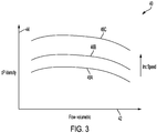
- FIG. 3 is a graph depicting a relation between normalized differential pressure and fluid flow and/or pump speed.
- graph 40 includes horizontal axis 42, vertical axis 44 and relations 46A, 46B, and 46C.
- Horizontal axis 42 is indicative of volumetric flow of a fluid being pumped by a centrifugal pump, such as centrifugal pump 22 depicted in FIG. 2 .
- Vertical axis 44 is indicative of normalized differential pressure of the fluid being pumped by the centrifugal pump (for a given fluid density). Normalized differential pressure is a ratio of the sensed differential pressure to the fluid density.
- Relations 46A-46Care indicative of relationships between the normalized differential pressure and the volumetric flow of the pumped fluid for different rotational speeds of the pump impeller, such as impeller 32 depicted in FIG. 2 .
- the measured pressure differential is not constant, even for a fluid with constant density.
- the only operable point in the relation between measured density and volumetric flow is at the vertical axis where volumetric flow is zero.
- rate of fluid flow must be either measured (or otherwise be known), or must be controlled to within a certain range about a target operating point.
- the flow rate can be maintained near zero by providing a small flowrate, as controlled, for example, by a pinhole orifice in the fuel outlet path.
- Such a low flow rate can facilitate fuel circulation, while maintaining fluid flow near the target operating point (e.g., near zero).
- a rate of fluid flow can be, for example, a flow rate corresponding to a measured differential pressure being within 0.1%, 0.5%, 1%, or 2% of the differential pressure measured for a zero fluid flow rate, for example.
- a measured flow rate is used in the determination of density of the aircraft fuel. For example, using a known relation between differential pressure and fluid flow and/or pump speed, accurate determination of aircraft fuel density can be determined based on impeller speed, measured flow rate, and measured differential pressure. Various ways of determining such accurate determinations of aircraft fuel density can be performed using such measured metrics, as will be described below.
- FIG. 4 is a block diagram of fuel system that simultaneously pumps and measures density of aircraft fuel using a single impeller.
- fuel system 12 includes centrifugal pump 22, first and second pressure sensors 24 and 26, and fuel density calculator 28.
- Fuel density calculator includes processor(s) 50, aircraft interface 52, and storage device(s) 54, and sensor interface 56.
- Processor(s) 50 can receive program instructions 54P from storage device(s) 54.
- Processor(s) 50 can be configured to calculate fuel density, based on received pressure sensor signals and on program instructions 54P.
- processor(s) 50 can be configured to receive pressure sensor signals, via sensor interface 56, indicative of measured fuel pressures P 1 and P 2 .
- Processor(s) 50 can calculate fuel density based on the received pressure sensor signals and provide the calculated density to other aircraft systems via aircraft interface 52.
- fuel density calculator 28 includes processor(s) 50, aircraft interface 52, storage device(s) 54, and sensor interface 56.
- fuel density calculator 28 and/or fuel system 12 can include more or fewer components.
- fuel system 12 can include a tachometer configured to measure a rotational velocity of the impeller and/or a rotational flow measurement sensor. The rotational velocity of the impeller as measured by a tachometer, can be indicative of the rotational frequency of the aircraft fuel.
- fuel density calculator can include a flow regulator configured to regulate, based at least in part on the calculated fuel density, fuel flow of the aircraft fuel.
- fuel density calculator 28 can be performed in one of various aircraft computational systems, such as, for example, an existing Full Authority Digital Engine Controller (FADEC) of the aircraft.
- FADEC Full Authority Digital Engine Controller
- Processor(s) 50 in one example, is configured to implement functionality and/or process instructions for execution within fuel density calculator 28.
- processor(s) 50 can be capable of processing instructions stored in storage device(s) 54.
- Examples of processor(s) 50 can include any one or more of a microprocessor, a controller, a digital signal processor(s) (DSP), an application specific integrated circuit (ASIC), a field-programmable gate array (FPGA), or other equivalent discrete or integrated logic circuitry.
- DSP digital signal processor
- ASIC application specific integrated circuit
- FPGA field-programmable gate array
- Storage device(s) 54 can be configured to store information within fuel density calculator 28 during operation.
- Storage device(s) 54 in some examples, is described as computer-readable storage media.
- a computer-readable storage medium can include a non-transitory medium.
- the term "non-transitory" can indicate that the storage medium is not embodied in a carrier wave or a propagated signal.
- a non-transitory storage medium can store data that can, over time, change (e.g., in RAM or cache).
- storage device(s) 54 is a temporary memory, meaning that a primary purpose of storage device(s) 54 is not long-term storage.
- Storage device(s) 54 in some examples, is described as volatile memory, meaning that storage device(s) 54 do not maintain stored contents when power to Fuel density calculator 28 is turned off. Examples of volatile memories can include random access memories (RAM), dynamic random access memories (DRAM), static random access memories (SRAM), and other forms of volatile memories.
- RAM random access memories
- DRAM dynamic random access memories
- SRAM static random access memories
- storage device(s) 54 is used to store program instructions for execution by processor(s) 50.
- Storage device(s) 54 in one example, is used by software or applications running on fuel density calculator 28 (e.g., a software program implementing fuel density calculation).
- Storage device(s) 54 can also include one or more computer-readable storage media.
- Storage device(s) 54 can be configured to store larger amounts of information than volatile memory.
- Storage device(s) 54 can further be configured for long-term storage of information.
- storage device(s) 54 include non-volatile storage elements. Examples of such non-volatile storage elements can include magnetic hard discs, optical discs, flash memories, or forms of electrically programmable memories (EPROM) or electrically erasable and programmable (EEPROM) memories.
- Aircraft interface 52 can be used to communicate information between fuel density calculator 28 and an aircraft. In some embodiments, such information can include aircraft conditions, flying conditions, and/or atmospheric conditions. In some embodiments, such information can include data processed by fuel density calculator 28, such as, for example, alert signals. Aircraft interface 52 can also include a communications module. Aircraft interface 52, in one example, utilizes the communications module to communicate with external devices via one or more networks, such as one or more wireless or wired networks or both.
- the communications module can be a network interface card, such as an Ethernet card, an optical transceiver, a radio frequency transceiver, or any other type of device that can send and receive information.
- network interfaces can include Bluetooth, 3G, 4G, and Wi-Fi radio computing devices as well as Universal Serial Bus (USB).
- communication with the aircraft can be performed via a communications bus, such as, for example, an Aeronautical Radio, Incorporated (ARINC) standard communications protocol.
- ARINC Aeronautical Radio, Incorporated
- aircraft communication with the aircraft can be performed via a communications bus, such as, for example, a Controller Area Network (CAN) bus.
- CAN Controller Area Network
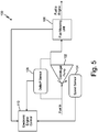
- FIG. 5 is a schematic diagram of a fuel system that simultaneously pumps fuel and measures fuel density based on a manufacturer's head curve.
- fuel system 100 includes centrifugal pump 102, speed sensing arrangement 104, flow-rate sensing arrangement 106, pressure sensing arrangement 108, and processor 110.
- Centrifugal pump 102 includes an impeller (not depicted) configured to pump the aircraft fuel.
- Speed sensing arrangement 104 is configured to determine a rotational frequency of the impeller while the centrifugal pump is pumping the aircraft fuel.
- Flow-rate sensing arrangement 104 is configured to measure flow rate of the aircraft fuel through centrifugal pump 102.
- Pressure sensing arrangement 108 is configured to measure pressure at two different points within or across centrifugal pump 102 or a differential pressure between the two different points while centrifugal pump 102 is pumping the aircraft fuel.
- Processor 110 is configured to calculate a density of the aircraft fuel based on the manufacturer's head curve.
- the manufacturer's head curve relates a normalized differential pressure to the rotational frequency and the flow rate.
- the normalized differential pressure is the differential pressure divided by the fluid density. Using this head curve along with the differential pressure, the rotational frequency, and the flow rate, the fluid density can be determined.
- Fuel system 100 depicted in FIG. 5 can determine a fluid density using a head curve pertaining to the specific centrifugal pump 102, using the measured parameters of differential pressure, impeller rotational frequency, and fluid flow rate. For example, measurements of impeller speed, fluid flow rate, and differential pressure can be provided as inputs, and a density of the fluid can be calculated using the head curve pertaining to centrifugal pump 102. These measured inputs can be used to calculate a theoretical fluid density using the head curve relation that relates such measured inputs to fluid density, such as, for example, a manufacturer-provided head curve relation. In some embodiments, temperature of the fluid being pumped by centrifugal pump 102 can be measured and used in addition to the above cited measurement inputs for determining the fluid density.
- the system includes a centrifugal pump including an impeller configured to pump the aircraft fuel.
- the system includes a speed sensing arrangement configured to determine a rotational frequency of the impeller while the centrifugal pump is pumping the aircraft fuel.
- the system includes a flow-rate sensing arrangement configured to measure flow rate of the aircraft fuel through the centrifugal pump.
- the system includes a pressure sensing arrangement configured to measure pressure at two different points within or across the centrifugal pump or a differential pressure between the two different points while the centrifugal pump is pumping the aircraft fuel.
- the system includes computer-readable memory containing data indicative of a head-curve relation corresponding to the centrifugal pump.
- the system also includes a processor configured to calculate a density of the aircraft fuel based on the head-curve relation, the rotational frequency, the flow rate, and either the pressures of the two different points or the differential pressure between the two different points
- the system of the preceding paragraph can optionally include, additionally and/or alternatively, any one or more of the following features, configurations and/or additional components:
- the flow-rate sensing arrangement can include a fuel metering unit configured to meter, based at least in part on the calculated fuel density, the aircraft fuel to an aircraft engine, wherein the fuel metering unit includes the flow-rate sensing arrangement.
- the fuel metering unit can include a flow regulator configured to regulate, based at least in part on the calculated fuel density, fuel flow of the aircraft fuel.
- pressure sensing arrangement can measure the differential pressure between inlet and outlet ports of the centrifugal pump.
- a further embodiment of any of the foregoing systems can further include a temperature sensor configured to measure the temperature of the aircraft fuel pumped by the centrifugal pump.
- the processor is configured to calculate a density of the aircraft fuel further based on the measured temperature of the aircraft fuel pumped by the centrifugal pump.
- impeller can be an open vane impeller.
- impeller can be a semi-open vane impeller.
- impeller can be a closed vane impeller.
- rotational frequency of the impeller can be indicative of a rotational frequency of the aircraft fuel about the impeller axis.
- the speed sensing arrangement can include a tachometer configured to measure a rotational frequency of the impeller, the rotational frequency being indicative of the rotational frequency of the aircraft fuel.
- centrifugal pump can be an axial flow pump.
- centrifugal pump can be a radial flow pump.
- Some embodiments relate to a method for simultaneously pumping and measuring density of aircraft fuel.
- the method includes pumping the aircraft fuel with a centrifugal pump.
- the method includes measuring flow rate of the aircraft fuel pumped by the centrifugal pump.
- the method includes measuring, while the centrifugal pump is pumping the aircraft fuel, pressure at two different points within the centrifugal pump or a differential pressure between the two different points.
- the method includes measuring a rotational frequency of an impeller of the centrifugal pump.
- the method includes retrieving, from computer-readable memory, data indicative of a head-curve relation characterizing the centrifugal pump.
- the method also includes calculating, via a processor, a density of the aircraft fuel based on the head-curve relation, the rotational frequency, the flow rate, and either the pressures of the two different points or the differential pressure between the two different points.
- the method of the preceding paragraph can optionally include, additionally and/or alternatively, any one or more of the following features, configurations and/or additional components:
- a further embodiment of the foregoing method can further include metering based at least in part on the calculated fuel density, the aircraft fuel to an aircraft engine.
- a further embodiment of any of the foregoing methods can further include regulating, based at least in part on the calculated fuel density, fuel flow of the aircraft fuel.
- measuring pressure at two different points can further include measuring the differential pressure between inlet and outlet ports of the centrifugal pump.
- a further embodiment of any of the foregoing methods can further include measuring temperature of the aircraft fuel in the centrifugal pump. Calculating a density of the aircraft fuel can be further based on the measured temperature of the aircraft fuel in the centrifugal pump.
- impeller can be an open vane impeller.
- impeller can be a semi-open vane impeller.
- impeller can be a closed vane impeller.
Landscapes
- Engineering & Computer Science (AREA)
- Chemical & Material Sciences (AREA)
- Combustion & Propulsion (AREA)
- General Physics & Mathematics (AREA)
- Physics & Mathematics (AREA)
- General Engineering & Computer Science (AREA)
- Mechanical Engineering (AREA)
- Analytical Chemistry (AREA)
- Immunology (AREA)
- Pathology (AREA)
- General Health & Medical Sciences (AREA)
- Biochemistry (AREA)
- Life Sciences & Earth Sciences (AREA)
- Health & Medical Sciences (AREA)
- Fluid Mechanics (AREA)
- Control Of Non-Positive-Displacement Pumps (AREA)
- Aviation & Aerospace Engineering (AREA)
- Measuring Volume Flow (AREA)
Abstract
Description
- This application is related to
U.S. Non-Provisional Application No. 16/659,150 filed October 21, 2019 - Fuel metering of an aircraft involves measurement of fuel density, which can change in response to changes in conditions. Temperature, for example, affects the density of fuels used in aircraft engines. The amount of energy contained in a particular volume of fuel is dependent on the density of the fuel. Thus, aircraft fuel systems measure density of the fuel so that accurate metering of fuel to the engines can be performed. Temperature variations, pressure variations and vibrations that are experienced on an aircraft in flight can make accurate measurements of fuel density difficult.
- Some embodiments relate to a system for simultaneously pumping and measuring density of an aircraft fuel. The system includes a centrifugal pump including an impeller configured to pump the aircraft fuel. The system includes a speed sensing arrangement configured to determine a rotational frequency of the impeller while the centrifugal pump is pumping the aircraft fuel. The system includes a flow-rate sensing arrangement configured to measure flow rate of the aircraft fuel through the centrifugal pump. The system includes a pressure sensing arrangement configured to measure pressure at two different points within or across the centrifugal pump or a differential pressure between the two different points while the centrifugal pump is pumping the aircraft fuel. The system includes computer-readable memory containing data indicative of a head-curve relation corresponding to the centrifugal pump. The system also includes a processor configured to calculate a density of the aircraft fuel based on the head-curve relation, the rotational frequency, the flow rate, and either the pressures of the two different points or the differential pressure between the two different points.
- Some embodiments relate to a method for simultaneously pumping and measuring density of aircraft fuel. The method includes pumping the aircraft fuel with a centrifugal pump. The method includes measuring flow rate of the aircraft fuel pumped by the centrifugal pump. The method includes measuring, while the centrifugal pump is pumping the aircraft fuel, pressure at two different points within the centrifugal pump or a differential pressure between the two different points. The method includes measuring a rotational frequency of an impeller of the centrifugal pump. The method includes retrieving, from computer-readable memory, data indicative of a head-curve relation characterizing the centrifugal pump. The method also includes calculating, via a processor, a density of the aircraft fuel based on the head-curve relation, the rotational frequency, the flow rate, and either the pressures of the two different points or the differential pressure between the two different points.
-
-
FIG. 1 is a schematic view of an aircraft engine supplied with fuel by a fuel system that simultaneously pumps and measures density of aircraft fuel using a single impeller. -
FIG. 2 shows cross-sectional views of a fuel system that simultaneously pumps and measures density of aircraft fuel using a single impeller. -
FIG. 3 is a graph depicting a relation between measured differential pressure and fluid flow and/or pump speed. -
FIG. 4 is a block diagram of fuel system that simultaneously pumps and measures density of aircraft fuel using a single impeller. -
FIG. 5 is a schematic diagram of a fuel system that simultaneously pumps fuel and measures fuel density based on a manufacturer's head curve. - Apparatus and associated methods relate to simultaneously pumping and measuring density of an aircraft fuel. The aircraft fuel is pumped by a centrifugal pump having an impeller. A rotational frequency of the impeller is determined while the centrifugal pump is pumping the aircraft fuel. Flow rate of the aircraft fuel through the centrifugal pump is sensed. Pressure of the aircraft fuel is measured at two different points within or across the centrifugal pump or a differential pressure is measured between the two different points while the centrifugal pump is pumping the aircraft fuel. Density of the aircraft fuel is determined based on a head-curve relation characterizing the centrifugal pump. The head-curve relation relates the fuel density to the rotational frequency, the flow rate, and pressures at the two different points or the differential pressure between the two different points.
-
FIG. 1 is a schematic view of an aircraft engine configured to be supplied with aircraft fuel by a fuel system. InFIG. 1 ,aircraft engine 10 includesfuel system 12.Fuel system 12 includesfuel pump 14,fuel metering unit 16,Fuel densimeter 18, andfuel control module 20. -
Fuel pump 14 receives fuel from a fuel inlet port connected to a fuel line and pumps the received fuel to an outlet port.Fuel densimeter 18 receives the fuel from the outlet port offuel pump 14, measures the density of the fuel, and provides fuel control module 20 a signal indicative of the measured density of the fuel.Fuel control module 20 controls thefuel metering unit 16, based at least in part on the measured density of the fuel.Fuel metering unit 16 then meters the fuel provided toaircraft engine 10 as controlled byfuel control module 20. Fuel densimeter includes a centrifugal pump and pressure sensors configured to measure fluid pressure at various radial distances from an impeller axis. -
FIG. 2 shows cross-sectional views of a densimeter that measures density of aircraft fuel. InFIG. 2 ,densimeter 12 includescentrifugal pump 22, first andsecond pressure sensors 24 and 26, andfuel density calculator 28.Centrifugal pump 22 haspump casing 30 in which residesimpeller 32.Pump casing 30 hasfuel inlet 36 through which the aircraft fuel is drawn. In some embodiments,pump casing 30 has a fuel outlet through which the aircraft fuel is pumped. The fuel outlet can be used to facilitate circulation of fuel throughpump casing 30.Impeller 32 is configured to rotate aboutimpeller axis 34.Impeller 32 has a plurality ofblades 32A-32D.Impeller 32, when rotated, causes the aircraft fuel to be circularly rotated withinpump casing 30, thereby creating a pressure differential between fuel located nearimpeller axis 34 and fuel located at a radial periphery ofpump casing 30.Impeller 32, when rotated, causes a pressure difference between a first fuel pressure at a first radial distance from theimpeller axis 34 and a second fuel pressure at a second radial distance from theimpeller axis 34. -
First pressure sensor 24 is configured to measure the first fuel pressure, and second pressure sensor 26 is configured to measure the second fuel pressure.Second pressure sensor 24 is further configured to measure second fuel pressure in a radial direction at the pump casing.Density calculator 28 configured to calculate density of the aircraft fuel based on the first and second fuel pressures as measured by first andsecond pressure sensors 24 and 26. - Densimeter is also depicted in
FIG. 2 as having motor and speed sensor 3 8. In some embodiments, motor andspeed sensor 38 can be electrically coupled todensimeter calculator 28, so thatdensimeter calculator 28 can control the rotational speed ofimpeller 32. -
Centrifugal pump 22 haspump casing 30 in which residesimpeller 32.Pump casing 30 hasfuel inlet 36 through which the aircraft fuel is drawn and, in some embodiments, a fuel outlet through which the aircraft fuel is pumped. In the depicted embodiment,fuel inlet 36 is aligned near or alongimpeller axis 34. The fuel outlet, if present, is at a radially distal location ofpump casing 30 as measured fromimpeller axis 34.Impeller 32 is configured to rotate aboutimpeller axis 34.Impeller 32 has a plurality ofblades 32A-32D.Impeller 32, when rotated, causes the aircraft fuel to be drawn fromfuel inlet 36 and to be expelled through the fuel outlet, if so equipped.Impeller 32, when rotated, also causes a pressure difference between first fuel pressure P1 at a first radial distance r1 from theimpeller axis 34 and second fuel pressure P2 at a second radial distance r2 from theimpeller axis 34. - As the impeller is rotated, a centrifugal pump imparts a rotational or circumferential component R to flow of the aircraft fuel being pumped. Because of this rotational component, a radial pressure gradient of the pumped fuel is produced. This radial pressure gradient varies for aircraft fuels of different densities. Therefore, such a pressure gradient can be indicative of the density of the aircraft fuel. For systems in which the first fuel pressure is measured along impeller axis 34 (i.e, the radial distance of
first pressure sensor 24 fromimpeller axis 34 is zero: r1 = 0), such a relation between density D and measured pressures can be given by:
impeller axis 34, and ω is the rotation frequency of aircraft fuel. The rotational frequency of the aircraft fuel can measured and/or calculated based on a rotational frequency of the impeller as measured by motor andspeed sensor 38. In some embodiments, a relation between the rotational frequency of the impeller and the rotational frequency of the aircraft fuel can be based on aircraft fuel dynamics. In some embodiments, the aircraft fuel dynamics of the system are such that the rotational frequency of the impeller and the rotational frequency of the aircraft fuel are substantially equal to one another. - Various embodiments have first and
second pressure sensors 24 and 26 located at various radial distances r1 and r2 fromimpeller axis 34. For example a ratio of the distance r1 to distance r2 can be less than 0.25. 0. 1, 0.05, or it can be 0.00 whenfirst pressure sensor 24 is aligned alongimpeller axis 34. - In the embodiment in
FIG. 2 ,centrifugal pump 22 is a zero flow pump, having no fuel outlet. For such a zero flow pump, the impeller can be designed to direct the fluid in purely circumferential directions aboutimpeller axis 34. Such circumferential directed impellers can also be used for pumps designed for small flow rates - flow rates that corresponding to operation near zero flow rate as described above. The impeller of such a zero flow pump can have substantial axial mirror symmetry, thereby having to axial direction that is preferential. - In the embodiment depicted in
FIG. 2 ,impeller 32 is an open vane impeller. An open vane impeller has blades, such asblades 32A-32D extending from a central hub. In some embodiments,impeller 32 can be a semi-open vane impeller. A semi-open vane impeller has a plate, which in some embodiments can be substantially circular, affixed to one axial side ofimpeller blades 32A-32D. In some embodiments,impeller 32 can be a closed vane impeller, which has plates on both axial sides ofimpeller blades 32A-32D. -
First pressure sensor 24 is configured to measure the first fuel pressure, and second pressure sensor 26 is configured to measure the second fuel pressure. Second pressure sensor 26 is further configured to measure second fuel pressure in a radial direction at the pump casing. Such a radial directive sensor can have a sensing membrane that has a normal vector aligned with a radial direction from the impeller axis. For example, the radial directive sensor can have a sensing membrane that is substantially conformal with an inside surface ofpump casing 22. Such a sensing membrane can deflect, in response to aircraft fuel pressure, in the radial direction that is parallel to the normal vector of the membrane.Fuel control module 20 can be configured to calculate density of the aircraft fuel based on the first and second fuel pressures as measured by first andsecond pressure sensors 24 and 26. - In some embodiments, instead of first and
second pressure sensors 24 and 26, a differential pressure sensor measure a differential pressure between two different radial locations r1 and r2 fromimpeller axis 34. For example, instead ofpressures sensors 24 and 26 at the radial locations r1 and r2 fromimpeller axis 34, a differential pressure sensor can be in fluid communication with ports located wherepressures sensors 24 and 26 are depicted inFIG. 2 . -
FIG. 3 is a graph depicting a relation between normalized differential pressure and fluid flow and/or pump speed. InFIG. 3 ,graph 40 includes horizontal axis 42, vertical axis 44 andrelations centrifugal pump 22 depicted inFIG. 2 . Vertical axis 44 is indicative of normalized differential pressure of the fluid being pumped by the centrifugal pump (for a given fluid density). Normalized differential pressure is a ratio of the sensed differential pressure to the fluid density.Relations 46A-46Care indicative of relationships between the normalized differential pressure and the volumetric flow of the pumped fluid for different rotational speeds of the pump impeller, such asimpeller 32 depicted inFIG. 2 . - As depicted in
FIG. 3 , for a given rotational speed, the measured pressure differential is not constant, even for a fluid with constant density. For embodiments in which no fluid flow is caused by rotation of impeller 32 (e.g., embodiments having no outlet port), such variable relations are not problematic. In such no-flow embodiments, the only operable point in the relation between measured density and volumetric flow is at the vertical axis where volumetric flow is zero. For embodiments that provide fluid flow via an outlet port, however, rate of fluid flow must be either measured (or otherwise be known), or must be controlled to within a certain range about a target operating point. For example, the flow rate can be maintained near zero by providing a small flowrate, as controlled, for example, by a pinhole orifice in the fuel outlet path. Such a low flow rate can facilitate fuel circulation, while maintaining fluid flow near the target operating point (e.g., near zero). Such a rate of fluid flow can be, for example, a flow rate corresponding to a measured differential pressure being within 0.1%, 0.5%, 1%, or 2% of the differential pressure measured for a zero fluid flow rate, for example. - In some embodiments, such as those which will be disclosed below with reference to
FIG. 5 , a measured flow rate is used in the determination of density of the aircraft fuel. For example, using a known relation between differential pressure and fluid flow and/or pump speed, accurate determination of aircraft fuel density can be determined based on impeller speed, measured flow rate, and measured differential pressure. Various ways of determining such accurate determinations of aircraft fuel density can be performed using such measured metrics, as will be described below. -
FIG. 4 is a block diagram of fuel system that simultaneously pumps and measures density of aircraft fuel using a single impeller. InFIG. 4 ,fuel system 12 includescentrifugal pump 22, first andsecond pressure sensors 24 and 26, andfuel density calculator 28. Fuel density calculator includes processor(s) 50,aircraft interface 52, and storage device(s) 54, andsensor interface 56. Processor(s) 50 can receiveprogram instructions 54P from storage device(s) 54. Processor(s) 50 can be configured to calculate fuel density, based on received pressure sensor signals and onprogram instructions 54P. For example, processor(s) 50 can be configured to receive pressure sensor signals, viasensor interface 56, indicative of measured fuel pressures P1 and P2. Processor(s) 50 can calculate fuel density based on the received pressure sensor signals and provide the calculated density to other aircraft systems viaaircraft interface 52. - As illustrated in
FIG. 4 ,fuel density calculator 28 includes processor(s) 50,aircraft interface 52, storage device(s) 54, andsensor interface 56. However, in certain examples,fuel density calculator 28 and/orfuel system 12 can include more or fewer components. For instance, in some embodiments,fuel system 12 can include a tachometer configured to measure a rotational velocity of the impeller and/or a rotational flow measurement sensor. The rotational velocity of the impeller as measured by a tachometer, can be indicative of the rotational frequency of the aircraft fuel. In some embodiments, fuel density calculator can include a flow regulator configured to regulate, based at least in part on the calculated fuel density, fuel flow of the aircraft fuel. In some examples,fuel density calculator 28 can be performed in one of various aircraft computational systems, such as, for example, an existing Full Authority Digital Engine Controller (FADEC) of the aircraft. - Processor(s) 50, in one example, is configured to implement functionality and/or process instructions for execution within
fuel density calculator 28. For instance, processor(s) 50 can be capable of processing instructions stored in storage device(s) 54. Examples of processor(s) 50 can include any one or more of a microprocessor, a controller, a digital signal processor(s) (DSP), an application specific integrated circuit (ASIC), a field-programmable gate array (FPGA), or other equivalent discrete or integrated logic circuitry. Processor(s) 50 can be configured to perform fuel density calculations. - Storage device(s) 54 can be configured to store information within
fuel density calculator 28 during operation. Storage device(s) 54, in some examples, is described as computer-readable storage media. In some examples, a computer-readable storage medium can include a non-transitory medium. The term "non-transitory" can indicate that the storage medium is not embodied in a carrier wave or a propagated signal. In certain examples, a non-transitory storage medium can store data that can, over time, change (e.g., in RAM or cache). In some examples, storage device(s) 54 is a temporary memory, meaning that a primary purpose of storage device(s) 54 is not long-term storage. Storage device(s) 54, in some examples, is described as volatile memory, meaning that storage device(s) 54 do not maintain stored contents when power toFuel density calculator 28 is turned off. Examples of volatile memories can include random access memories (RAM), dynamic random access memories (DRAM), static random access memories (SRAM), and other forms of volatile memories. In some examples, storage device(s) 54 is used to store program instructions for execution by processor(s) 50. Storage device(s) 54, in one example, is used by software or applications running on fuel density calculator 28 (e.g., a software program implementing fuel density calculation). - Storage device(s) 54, in some examples, can also include one or more computer-readable storage media. Storage device(s) 54 can be configured to store larger amounts of information than volatile memory. Storage device(s) 54 can further be configured for long-term storage of information. In some examples, storage device(s) 54 include non-volatile storage elements. Examples of such non-volatile storage elements can include magnetic hard discs, optical discs, flash memories, or forms of electrically programmable memories (EPROM) or electrically erasable and programmable (EEPROM) memories.
-
Aircraft interface 52 can be used to communicate information betweenfuel density calculator 28 and an aircraft. In some embodiments, such information can include aircraft conditions, flying conditions, and/or atmospheric conditions. In some embodiments, such information can include data processed byfuel density calculator 28, such as, for example, alert signals.Aircraft interface 52 can also include a communications module.Aircraft interface 52, in one example, utilizes the communications module to communicate with external devices via one or more networks, such as one or more wireless or wired networks or both. The communications module can be a network interface card, such as an Ethernet card, an optical transceiver, a radio frequency transceiver, or any other type of device that can send and receive information. Other examples of such network interfaces can include Bluetooth, 3G, 4G, and Wi-Fi radio computing devices as well as Universal Serial Bus (USB). In some embodiments, communication with the aircraft can be performed via a communications bus, such as, for example, an Aeronautical Radio, Incorporated (ARINC) standard communications protocol. In an exemplary embodiment, aircraft communication with the aircraft can be performed via a communications bus, such as, for example, a Controller Area Network (CAN) bus. -
FIG. 5 is a schematic diagram of a fuel system that simultaneously pumps fuel and measures fuel density based on a manufacturer's head curve. InFIG. 5 ,fuel system 100 includescentrifugal pump 102,speed sensing arrangement 104, flow-rate sensing arrangement 106,pressure sensing arrangement 108, andprocessor 110.Centrifugal pump 102 includes an impeller (not depicted) configured to pump the aircraft fuel.Speed sensing arrangement 104 is configured to determine a rotational frequency of the impeller while the centrifugal pump is pumping the aircraft fuel. Flow-rate sensing arrangement 104 is configured to measure flow rate of the aircraft fuel throughcentrifugal pump 102.Pressure sensing arrangement 108 is configured to measure pressure at two different points within or acrosscentrifugal pump 102 or a differential pressure between the two different points whilecentrifugal pump 102 is pumping the aircraft fuel.Processor 110 is configured to calculate a density of the aircraft fuel based on the manufacturer's head curve. The manufacturer's head curve relates a normalized differential pressure to the rotational frequency and the flow rate. The normalized differential pressure is the differential pressure divided by the fluid density. Using this head curve along with the differential pressure, the rotational frequency, and the flow rate, the fluid density can be determined. -
Fuel system 100 depicted inFIG. 5 can determine a fluid density using a head curve pertaining to the specificcentrifugal pump 102, using the measured parameters of differential pressure, impeller rotational frequency, and fluid flow rate. For example, measurements of impeller speed, fluid flow rate, and differential pressure can be provided as inputs, and a density of the fluid can be calculated using the head curve pertaining tocentrifugal pump 102. These measured inputs can be used to calculate a theoretical fluid density using the head curve relation that relates such measured inputs to fluid density, such as, for example, a manufacturer-provided head curve relation. In some embodiments, temperature of the fluid being pumped bycentrifugal pump 102 can be measured and used in addition to the above cited measurement inputs for determining the fluid density. - The following are non-exclusive descriptions of possible embodiments of the present invention.
- Some embodiments relate to a system for simultaneously pumping and measuring density of an aircraft fuel. The system includes a centrifugal pump including an impeller configured to pump the aircraft fuel. The system includes a speed sensing arrangement configured to determine a rotational frequency of the impeller while the centrifugal pump is pumping the aircraft fuel. The system includes a flow-rate sensing arrangement configured to measure flow rate of the aircraft fuel through the centrifugal pump. The system includes a pressure sensing arrangement configured to measure pressure at two different points within or across the centrifugal pump or a differential pressure between the two different points while the centrifugal pump is pumping the aircraft fuel. The system includes computer-readable memory containing data indicative of a head-curve relation corresponding to the centrifugal pump. The system also includes a processor configured to calculate a density of the aircraft fuel based on the head-curve relation, the rotational frequency, the flow rate, and either the pressures of the two different points or the differential pressure between the two different points
- The system of the preceding paragraph can optionally include, additionally and/or alternatively, any one or more of the following features, configurations and/or additional components:
- A further embodiment of the foregoing system, wherein the flow-rate sensing arrangement can include a fuel metering unit configured to meter, based at least in part on the calculated fuel density, the aircraft fuel to an aircraft engine, wherein the fuel metering unit includes the flow-rate sensing arrangement.
- A further embodiment of any of the foregoing systems, wherein the fuel metering unit can include a flow regulator configured to regulate, based at least in part on the calculated fuel density, fuel flow of the aircraft fuel.
- A further embodiment of any of the foregoing systems, wherein the pressure sensing arrangement can measure the differential pressure between inlet and outlet ports of the centrifugal pump.
- A further embodiment of any of the foregoing systems can further include a temperature sensor configured to measure the temperature of the aircraft fuel pumped by the centrifugal pump. The processor is configured to calculate a density of the aircraft fuel further based on the measured temperature of the aircraft fuel pumped by the centrifugal pump.
- A further embodiment of any of the foregoing systems, wherein the impeller can be an open vane impeller.
- A further embodiment of any of the foregoing systems, wherein the impeller can be a semi-open vane impeller.
- A further embodiment of any of the foregoing systems, wherein the impeller can be a closed vane impeller.
- A further embodiment of any of the foregoing systems, wherein the rotational frequency of the impeller can be indicative of a rotational frequency of the aircraft fuel about the impeller axis.
- A further embodiment of any of the foregoing systems, wherein the speed sensing arrangement can include a tachometer configured to measure a rotational frequency of the impeller, the rotational frequency being indicative of the rotational frequency of the aircraft fuel.
- A further embodiment of any of the foregoing systems, wherein centrifugal pump can be an axial flow pump.
- A further embodiment of any of the foregoing systems, wherein centrifugal pump can be a radial flow pump.
- Some embodiments relate to a method for simultaneously pumping and measuring density of aircraft fuel. The method includes pumping the aircraft fuel with a centrifugal pump. The method includes measuring flow rate of the aircraft fuel pumped by the centrifugal pump. The method includes measuring, while the centrifugal pump is pumping the aircraft fuel, pressure at two different points within the centrifugal pump or a differential pressure between the two different points. The method includes measuring a rotational frequency of an impeller of the centrifugal pump. The method includes retrieving, from computer-readable memory, data indicative of a head-curve relation characterizing the centrifugal pump. The method also includes calculating, via a processor, a density of the aircraft fuel based on the head-curve relation, the rotational frequency, the flow rate, and either the pressures of the two different points or the differential pressure between the two different points.
- The method of the preceding paragraph can optionally include, additionally and/or alternatively, any one or more of the following features, configurations and/or additional components:
- A further embodiment of the foregoing method can further include metering based at least in part on the calculated fuel density, the aircraft fuel to an aircraft engine.
- A further embodiment of any of the foregoing methods can further include regulating, based at least in part on the calculated fuel density, fuel flow of the aircraft fuel.
- A further embodiment of any of the foregoing methods, wherein measuring pressure at two different points can further include measuring the differential pressure between inlet and outlet ports of the centrifugal pump.
- A further embodiment of any of the foregoing methods can further include measuring temperature of the aircraft fuel in the centrifugal pump. Calculating a density of the aircraft fuel can be further based on the measured temperature of the aircraft fuel in the centrifugal pump.
- A further embodiment of any of the foregoing methods, wherein the impeller can be an open vane impeller.
- A further embodiment of any of the foregoing methods, wherein the impeller can be a semi-open vane impeller.
- A further embodiment of any of the foregoing methods, wherein the impeller can be a closed vane impeller.
- While the invention has been described with reference to an exemplary embodiment(s), it will be understood by those skilled in the art that various changes may be made and equivalents may be substituted for elements thereof without departing from the scope of the invention as defined by the claims. In addition, many modifications may be made to adapt a particular situation or material to the teachings of the invention without departing from the scope thereof. Therefore, it is intended that the invention not be limited to the particular embodiment(s) disclosed, but that the invention will include all embodiments falling within the scope of the appended claims.
Claims (15)
- A system for simultaneously pumping and measuring density of an aircraft fuel, the system comprising:a centrifugal pump (22) including an impeller (32) configured to pump the aircraft fuel;a speed sensing arrangement (104) configured to determine a rotational frequency of the impeller while the centrifugal pump is pumping the aircraft fuel;a flow-rate sensing arrangement (106)) configured to measure flow rate of the aircraft fuel through the centrifugal pump;a pressure sensing arrangement (108) configured to measure pressure at two different points within or across the centrifugal pump or a differential pressure between the two different points while the centrifugal pump is pumping the aircraft fuel;computer-readable memory (54) containing data indicative of a head-curve relation corresponding to the centrifugal pump; anda processor (50) configured to calculate a density of the aircraft fuel based on the head-curve relation, the rotational frequency, the flow rate, and either the pressures of the two different points or the differential pressure between the two different points.
- The system of claim 1, wherein the flow-rate sensing arrangement comprises:
a fuel metering unit (16) configured to meter, based at least in part on the calculated fuel density, the aircraft fuel to an aircraft engine, wherein the fuel metering unit includes the flow-rate sensing arrangement. - The system of claim 2, wherein the fuel metering unit comprises:
a flow regulator (20) configured to regulate, based at least in part on the calculated fuel density, fuel flow of the aircraft fuel. - The system of any preceding claim, wherein the pressure sensing arrangement measures the differential pressure between inlet and outlet ports of the centrifugal pump.
- The system of any preceding claim, further comprising:a temperature sensor configured to measure the temperature of the aircraft fuel pumped by the centrifugal pump,wherein the processor is configured to calculate a density of the aircraft fuel further based on the measured temperature of the aircraft fuel pumped by the centrifugal pump.
- The system of any preceding claim, wherein the impeller is an open vane impeller, or wherein the impeller is a semi-open vane impeller, or wherein the impeller is a closed vane impeller.
- The system of any preceding claim, wherein the rotational frequency of the impeller is indicative of a rotational frequency of the aircraft fuel about the impeller axis.
- The system of any preceding claim, wherein the speed sensing arrangement comprises:
a tachometer configured to measure a rotational frequency of the impeller, the rotational frequency being indicative of the rotational frequency of the aircraft fuel. - The system of any preceding claim, wherein centrifugal pump is an axial flow pump, or wherein centrifugal pump is a radial flow pump.
- A method for simultaneously pumping and measuring density of aircraft fuel, the method comprising:pumping the aircraft fuel with a centrifugal pump;measuring flow rate of the aircraft fuel pumped by the centrifugal pump;measuring, while the centrifugal pump is pumping the aircraft fuel, pressure at two different points within the centrifugal pump or a differential pressure between the two different points;measuring a rotational frequency of an impeller of the centrifugal pump;retrieving, from computer-readable memory, data indicative of a head-curve relation characterizing the centrifugal pump; andcalculating, via a processor, a density of the aircraft fuel based on the head-curve relation, the rotational frequency, the flow rate, and either the pressures of the two different points or the differential pressure between the two different points.
- The method of claim 10, further comprising:
metering based at least in part on the calculated fuel density, the aircraft fuel to an aircraft engine. - The method of claim 10 or 11, further comprising:
regulating, based at least in part on the calculated fuel density, fuel flow of the aircraft fuel. - The method of claim 10, 11 or 12, wherein measuring pressure at two different points includes:
measuring the differential pressure between inlet and outlet ports of the centrifugal pump. - The method of any of claims 10 to 13, further comprising:measuring temperature of the aircraft fuel in the centrifugal pump,wherein calculating a density of the aircraft fuel is further based on the measured temperature of the aircraft fuel in the centrifugal pump.
- The method of any of claims 10 to 14, wherein the impeller is an open vane impeller, or wherein the impeller is a semi-open vane impeller, or wherein the impeller is a closed vane impeller.
Applications Claiming Priority (1)
| Application Number | Priority Date | Filing Date | Title |
|---|---|---|---|
| US16/678,905 US11635031B2 (en) | 2019-11-08 | 2019-11-08 | Simultaneously pumping and measuring density of aircraft fuel |
Publications (2)
| Publication Number | Publication Date |
|---|---|
| EP3819600A1 true EP3819600A1 (en) | 2021-05-12 |
| EP3819600B1 EP3819600B1 (en) | 2024-10-30 |
Family
ID=73198186
Family Applications (1)
| Application Number | Title | Priority Date | Filing Date |
|---|---|---|---|
| EP20206467.1A Active EP3819600B1 (en) | 2019-11-08 | 2020-11-09 | Simultaneously pumping and measuring density of aircraft fuel |
Country Status (2)
| Country | Link |
|---|---|
| US (1) | US11635031B2 (en) |
| EP (1) | EP3819600B1 (en) |
Cited By (1)
| Publication number | Priority date | Publication date | Assignee | Title |
|---|---|---|---|---|
| CN113251192A (en) * | 2021-06-08 | 2021-08-13 | 中国空气动力研究与发展中心低速空气动力研究所 | Digital valve control system and control method by considering valve response time |
Families Citing this family (1)
| Publication number | Priority date | Publication date | Assignee | Title |
|---|---|---|---|---|
| CN115144039B (en) * | 2022-08-30 | 2026-02-06 | 中国航发沈阳发动机研究所 | Method for determining fuel oil return flow in aero-engine |
Citations (3)
| Publication number | Priority date | Publication date | Assignee | Title |
|---|---|---|---|---|
| US4108574A (en) * | 1977-01-21 | 1978-08-22 | International Paper Company | Apparatus and method for the indirect measurement and control of the flow rate of a liquid in a piping system |
| WO1997024596A1 (en) * | 1995-12-27 | 1997-07-10 | A. Ahlström Osakeyhtiö | Method and apparatus for determining physical variables of a slurry or liquid |
| US20160245188A1 (en) * | 2015-02-19 | 2016-08-25 | United Technologies Corporation | Fuel flow estimation and control system and method in a gas turbine engine |
Family Cites Families (16)
| Publication number | Priority date | Publication date | Assignee | Title |
|---|---|---|---|---|
| US3028748A (en) * | 1960-01-18 | 1962-04-10 | Curtiss Wright Corp | Liquid density computer |
| US4429528A (en) | 1980-01-22 | 1984-02-07 | Plessey Overseas Limited | Emergency fuel system |
| FR2482301A1 (en) * | 1980-05-12 | 1981-11-13 | Snecma | Fluid density measuring instrument for continuous measurement - uses sensor to detect pressure variations when fluid is subjected to centrifugal force |
| US4508127A (en) | 1983-03-30 | 1985-04-02 | The Garrett Corporation | Fuel mass flow measurement and control system |
| SU1242755A1 (en) * | 1984-12-07 | 1986-07-07 | Горьковский Ордена Трудового Красного Знамени Институт Инженеров Водного Транспорта | Method of determining density of liquid media |
| US5138559A (en) | 1989-08-28 | 1992-08-11 | The Boeing Company | System and method for measuring liquid mass quantity |
| US5129264A (en) * | 1990-12-07 | 1992-07-14 | Goulds Pumps, Incorporated | Centrifugal pump with flow measurement |
| FR2882098B1 (en) | 2005-02-17 | 2011-07-15 | Hispano Suiza Sa | FUEL FLOW REGULATION SUPPLYING A GAS TURBINE ENGINE |
| US7426960B2 (en) * | 2005-05-03 | 2008-09-23 | Luca Technologies, Inc. | Biogenic fuel gas generation in geologic hydrocarbon deposits |
| US7784487B2 (en) * | 2007-10-24 | 2010-08-31 | Honeywell International Inc. | Fuel metering valve assembly including thermal compensation mechanism |
| FR2945075B1 (en) | 2009-04-29 | 2015-06-05 | Snecma | METHOD AND DEVICE FOR FEEDING A TURBOMACHINE CHAMBER WITH A REGULATED FUEL FLOW |
| US20120166110A1 (en) | 2010-12-27 | 2012-06-28 | Jonathan Paul Wilson | Method and system for component resistance to flow |
| JP6102893B2 (en) * | 2014-11-14 | 2017-03-29 | トヨタ自動車株式会社 | Fuel cell system and vehicle equipped with fuel cell |
| US9784175B2 (en) * | 2015-06-01 | 2017-10-10 | Ford Global Technologies, Llc | Internal combustion engine and coolant pump |
| EP3179077B1 (en) * | 2015-12-11 | 2018-09-12 | Airbus Operations, S.L. | Fuel control system for a gas turbine engine of an aircraft |
| FR3069021B1 (en) * | 2017-07-13 | 2019-07-26 | Safran Aircraft Engines | FUEL DOSING SYSTEM AND METHOD COMPRISING VARIABILITY OF FUEL DENSITY |
-
2019
- 2019-11-08 US US16/678,905 patent/US11635031B2/en active Active
-
2020
- 2020-11-09 EP EP20206467.1A patent/EP3819600B1/en active Active
Patent Citations (3)
| Publication number | Priority date | Publication date | Assignee | Title |
|---|---|---|---|---|
| US4108574A (en) * | 1977-01-21 | 1978-08-22 | International Paper Company | Apparatus and method for the indirect measurement and control of the flow rate of a liquid in a piping system |
| WO1997024596A1 (en) * | 1995-12-27 | 1997-07-10 | A. Ahlström Osakeyhtiö | Method and apparatus for determining physical variables of a slurry or liquid |
| US20160245188A1 (en) * | 2015-02-19 | 2016-08-25 | United Technologies Corporation | Fuel flow estimation and control system and method in a gas turbine engine |
Non-Patent Citations (1)
| Title |
|---|
| CLAIRE SOARES ED - SOARES ET AL: "7 - Gas Turbine Fuel Systems and Fuels", 1 January 2008, GAS TURBINES : A HANDBOOK OF AIR, LAND, AND SEA APPLICATIONS, AMSTERDAM [U.A.] : ELSEVIER/BUTTERWORTH-HEINEMANN, NL, PAGE(S) 213 - 291, ISBN: 978-0-7506-7969-5, XP008128647 * |
Cited By (1)
| Publication number | Priority date | Publication date | Assignee | Title |
|---|---|---|---|---|
| CN113251192A (en) * | 2021-06-08 | 2021-08-13 | 中国空气动力研究与发展中心低速空气动力研究所 | Digital valve control system and control method by considering valve response time |
Also Published As
| Publication number | Publication date |
|---|---|
| US20210139159A1 (en) | 2021-05-13 |
| EP3819600B1 (en) | 2024-10-30 |
| US11635031B2 (en) | 2023-04-25 |
Similar Documents
| Publication | Publication Date | Title |
|---|---|---|
| EP3819502B1 (en) | Simultaneously pumping and measuring density of aircraft fuel | |
| CA2847640C (en) | Portable diagnostic analysis of gas meter and electronic corrector | |
| EP3819600B1 (en) | Simultaneously pumping and measuring density of aircraft fuel | |
| CA1094349A (en) | Apparatus and method for the indirect measurement and control of the flow rate of a liquid in a piping system | |
| US20140260674A1 (en) | Viscosity dependent flow meter for use in fuel dispensing environments | |
| CN103180576A (en) | Control of a fuel metering device for turbomachine | |
| CN101852636A (en) | Fuel Quantity Calculation Method for UAV Fuel Tank | |
| US11275008B2 (en) | Measuring density of aircraft fuel using a centrifugal fluid pump | |
| USRE36401E (en) | Tandem rotor turbine meter and field calibration module | |
| US20230349741A1 (en) | Measurement of flow rate from the electrical impedances of piezoelectric transducers | |
| US10465674B2 (en) | Method and system for determining a pump setpoint | |
| US12004848B2 (en) | Blood flow meter | |
| US11821773B1 (en) | Ultrasonic fluid meter incorporating two pressure sensors | |
| JPH01280698A (en) | Indicating or controlling method for flow amount of pump using head characteristics and calibrating method of head characteristics | |
| US4491026A (en) | Liquid flow meter | |
| US20240352939A1 (en) | Method for quantitatively determining current operating-state-dependent variables, more particularly the current conveyed volumetric flow rate, or a fan, and fan for application of the method | |
| Miedema | Spillage models for a cutter head in dredging sand or gravel | |
| KR102715951B1 (en) | System and method for calculating a flow rate of axial fan | |
| US11965763B2 (en) | Determining fluid flow across rotary pump | |
| KR101864875B1 (en) | Slurry pump control system and method using slurry concentration measurement | |
| US20230175515A1 (en) | Method of setting up an electrical motor speed control in a fluidic system | |
| CN119687002A (en) | A sensorless flow and head detection method and device for water pump system | |
| Schweiger | Flow in centrifugal pumps working at part capacity | |
| JPH0463239B2 (en) | ||
| RU2021121506A (en) | SYSTEM AND METHOD FOR ROTATION CONTROL OF AIRCRAFT GAS TURBINE ENGINE WITH FAILURE CONTROL |
Legal Events
| Date | Code | Title | Description |
|---|---|---|---|
| PUAI | Public reference made under article 153(3) epc to a published international application that has entered the european phase |
Free format text: ORIGINAL CODE: 0009012 |
|
| STAA | Information on the status of an ep patent application or granted ep patent |
Free format text: STATUS: THE APPLICATION HAS BEEN PUBLISHED |
|
| AK | Designated contracting states |
Kind code of ref document: A1 Designated state(s): AL AT BE BG CH CY CZ DE DK EE ES FI FR GB GR HR HU IE IS IT LI LT LU LV MC MK MT NL NO PL PT RO RS SE SI SK SM TR |
|
| STAA | Information on the status of an ep patent application or granted ep patent |
Free format text: STATUS: REQUEST FOR EXAMINATION WAS MADE |
|
| 17P | Request for examination filed |
Effective date: 20211112 |
|
| RBV | Designated contracting states (corrected) |
Designated state(s): AL AT BE BG CH CY CZ DE DK EE ES FI FR GB GR HR HU IE IS IT LI LT LU LV MC MK MT NL NO PL PT RO RS SE SI SK SM TR |
|
| STAA | Information on the status of an ep patent application or granted ep patent |
Free format text: STATUS: EXAMINATION IS IN PROGRESS |
|
| 17Q | First examination report despatched |
Effective date: 20220624 |
|
| REG | Reference to a national code |
Ref legal event code: R079 Free format text: PREVIOUS MAIN CLASS: G01F0001000000 Ipc: G01N0009320000 Ref country code: DE Ref document number: 602020040213 Country of ref document: DE |
|
| GRAP | Despatch of communication of intention to grant a patent |
Free format text: ORIGINAL CODE: EPIDOSNIGR1 |
|
| STAA | Information on the status of an ep patent application or granted ep patent |
Free format text: STATUS: GRANT OF PATENT IS INTENDED |
|
| RIC1 | Information provided on ipc code assigned before grant |
Ipc: G01N 9/26 20060101ALI20240516BHEP Ipc: F04D 15/00 20060101ALI20240516BHEP Ipc: F04D 7/02 20060101ALI20240516BHEP Ipc: F02C 9/26 20060101ALI20240516BHEP Ipc: F02C 7/22 20060101ALI20240516BHEP Ipc: G01N 9/30 20060101ALI20240516BHEP Ipc: G01F 1/00 20060101ALI20240516BHEP Ipc: G01F 13/00 20060101ALI20240516BHEP Ipc: G01F 1/86 20060101ALI20240516BHEP Ipc: G01N 9/32 20060101AFI20240516BHEP |
|
| INTG | Intention to grant announced |
Effective date: 20240619 |
|
| GRAS | Grant fee paid |
Free format text: ORIGINAL CODE: EPIDOSNIGR3 |
|
| GRAA | (expected) grant |
Free format text: ORIGINAL CODE: 0009210 |
|
| STAA | Information on the status of an ep patent application or granted ep patent |
Free format text: STATUS: THE PATENT HAS BEEN GRANTED |
|
| AK | Designated contracting states |
Kind code of ref document: B1 Designated state(s): AL AT BE BG CH CY CZ DE DK EE ES FI FR GB GR HR HU IE IS IT LI LT LU LV MC MK MT NL NO PL PT RO RS SE SI SK SM TR |
|
| REG | Reference to a national code |
Ref country code: GB Ref legal event code: FG4D |
|
| REG | Reference to a national code |
Ref country code: CH Ref legal event code: EP |
|
| REG | Reference to a national code |
Ref country code: DE Ref legal event code: R096 Ref document number: 602020040213 Country of ref document: DE |
|
| REG | Reference to a national code |
Ref country code: IE Ref legal event code: FG4D |
|
| REG | Reference to a national code |
Ref country code: LT Ref legal event code: MG9D |
|
| REG | Reference to a national code |
Ref country code: NL Ref legal event code: MP Effective date: 20241030 |
|
| PG25 | Lapsed in a contracting state [announced via postgrant information from national office to epo] |
Ref country code: IS Free format text: LAPSE BECAUSE OF FAILURE TO SUBMIT A TRANSLATION OF THE DESCRIPTION OR TO PAY THE FEE WITHIN THE PRESCRIBED TIME-LIMIT Effective date: 20250228 Ref country code: HR Free format text: LAPSE BECAUSE OF FAILURE TO SUBMIT A TRANSLATION OF THE DESCRIPTION OR TO PAY THE FEE WITHIN THE PRESCRIBED TIME-LIMIT Effective date: 20241030 Ref country code: PT Free format text: LAPSE BECAUSE OF FAILURE TO SUBMIT A TRANSLATION OF THE DESCRIPTION OR TO PAY THE FEE WITHIN THE PRESCRIBED TIME-LIMIT Effective date: 20250228 |
|
| PG25 | Lapsed in a contracting state [announced via postgrant information from national office to epo] |
Ref country code: FI Free format text: LAPSE BECAUSE OF FAILURE TO SUBMIT A TRANSLATION OF THE DESCRIPTION OR TO PAY THE FEE WITHIN THE PRESCRIBED TIME-LIMIT Effective date: 20241030 Ref country code: NL Free format text: LAPSE BECAUSE OF FAILURE TO SUBMIT A TRANSLATION OF THE DESCRIPTION OR TO PAY THE FEE WITHIN THE PRESCRIBED TIME-LIMIT Effective date: 20241030 |
|
| REG | Reference to a national code |
Ref country code: AT Ref legal event code: MK05 Ref document number: 1737306 Country of ref document: AT Kind code of ref document: T Effective date: 20241030 |
|
| PG25 | Lapsed in a contracting state [announced via postgrant information from national office to epo] |
Ref country code: BG Free format text: LAPSE BECAUSE OF FAILURE TO SUBMIT A TRANSLATION OF THE DESCRIPTION OR TO PAY THE FEE WITHIN THE PRESCRIBED TIME-LIMIT Effective date: 20241030 |
|
| PG25 | Lapsed in a contracting state [announced via postgrant information from national office to epo] |
Ref country code: ES Free format text: LAPSE BECAUSE OF FAILURE TO SUBMIT A TRANSLATION OF THE DESCRIPTION OR TO PAY THE FEE WITHIN THE PRESCRIBED TIME-LIMIT Effective date: 20241030 |
|
| PG25 | Lapsed in a contracting state [announced via postgrant information from national office to epo] |
Ref country code: NO Free format text: LAPSE BECAUSE OF FAILURE TO SUBMIT A TRANSLATION OF THE DESCRIPTION OR TO PAY THE FEE WITHIN THE PRESCRIBED TIME-LIMIT Effective date: 20250130 |
|
| PG25 | Lapsed in a contracting state [announced via postgrant information from national office to epo] |
Ref country code: LV Free format text: LAPSE BECAUSE OF FAILURE TO SUBMIT A TRANSLATION OF THE DESCRIPTION OR TO PAY THE FEE WITHIN THE PRESCRIBED TIME-LIMIT Effective date: 20241030 Ref country code: GR Free format text: LAPSE BECAUSE OF FAILURE TO SUBMIT A TRANSLATION OF THE DESCRIPTION OR TO PAY THE FEE WITHIN THE PRESCRIBED TIME-LIMIT Effective date: 20250131 Ref country code: AT Free format text: LAPSE BECAUSE OF FAILURE TO SUBMIT A TRANSLATION OF THE DESCRIPTION OR TO PAY THE FEE WITHIN THE PRESCRIBED TIME-LIMIT Effective date: 20241030 |
|
| PG25 | Lapsed in a contracting state [announced via postgrant information from national office to epo] |
Ref country code: PL Free format text: LAPSE BECAUSE OF FAILURE TO SUBMIT A TRANSLATION OF THE DESCRIPTION OR TO PAY THE FEE WITHIN THE PRESCRIBED TIME-LIMIT Effective date: 20241030 |
|
| PG25 | Lapsed in a contracting state [announced via postgrant information from national office to epo] |
Ref country code: RS Free format text: LAPSE BECAUSE OF FAILURE TO SUBMIT A TRANSLATION OF THE DESCRIPTION OR TO PAY THE FEE WITHIN THE PRESCRIBED TIME-LIMIT Effective date: 20250130 |
|
| REG | Reference to a national code |
Ref country code: CH Ref legal event code: PL |
|
| PG25 | Lapsed in a contracting state [announced via postgrant information from national office to epo] |
Ref country code: SM Free format text: LAPSE BECAUSE OF FAILURE TO SUBMIT A TRANSLATION OF THE DESCRIPTION OR TO PAY THE FEE WITHIN THE PRESCRIBED TIME-LIMIT Effective date: 20241030 |
|
| PG25 | Lapsed in a contracting state [announced via postgrant information from national office to epo] |
Ref country code: MC Free format text: LAPSE BECAUSE OF FAILURE TO SUBMIT A TRANSLATION OF THE DESCRIPTION OR TO PAY THE FEE WITHIN THE PRESCRIBED TIME-LIMIT Effective date: 20241030 |
|
| PG25 | Lapsed in a contracting state [announced via postgrant information from national office to epo] |
Ref country code: DK Free format text: LAPSE BECAUSE OF FAILURE TO SUBMIT A TRANSLATION OF THE DESCRIPTION OR TO PAY THE FEE WITHIN THE PRESCRIBED TIME-LIMIT Effective date: 20241030 |
|
| PG25 | Lapsed in a contracting state [announced via postgrant information from national office to epo] |
Ref country code: LU Free format text: LAPSE BECAUSE OF NON-PAYMENT OF DUE FEES Effective date: 20241109 |
|
| REG | Reference to a national code |
Ref country code: CH Ref legal event code: PL |
|
| PG25 | Lapsed in a contracting state [announced via postgrant information from national office to epo] |
Ref country code: EE Free format text: LAPSE BECAUSE OF FAILURE TO SUBMIT A TRANSLATION OF THE DESCRIPTION OR TO PAY THE FEE WITHIN THE PRESCRIBED TIME-LIMIT Effective date: 20241030 |
|
| PG25 | Lapsed in a contracting state [announced via postgrant information from national office to epo] |
Ref country code: CH Free format text: LAPSE BECAUSE OF NON-PAYMENT OF DUE FEES Effective date: 20241130 |
|
| PG25 | Lapsed in a contracting state [announced via postgrant information from national office to epo] |
Ref country code: RO Free format text: LAPSE BECAUSE OF FAILURE TO SUBMIT A TRANSLATION OF THE DESCRIPTION OR TO PAY THE FEE WITHIN THE PRESCRIBED TIME-LIMIT Effective date: 20241030 |
|
| PG25 | Lapsed in a contracting state [announced via postgrant information from national office to epo] |
Ref country code: SK Free format text: LAPSE BECAUSE OF FAILURE TO SUBMIT A TRANSLATION OF THE DESCRIPTION OR TO PAY THE FEE WITHIN THE PRESCRIBED TIME-LIMIT Effective date: 20241030 |
|
| PG25 | Lapsed in a contracting state [announced via postgrant information from national office to epo] |
Ref country code: CZ Free format text: LAPSE BECAUSE OF FAILURE TO SUBMIT A TRANSLATION OF THE DESCRIPTION OR TO PAY THE FEE WITHIN THE PRESCRIBED TIME-LIMIT Effective date: 20241030 |
|
| PG25 | Lapsed in a contracting state [announced via postgrant information from national office to epo] |
Ref country code: IT Free format text: LAPSE BECAUSE OF FAILURE TO SUBMIT A TRANSLATION OF THE DESCRIPTION OR TO PAY THE FEE WITHIN THE PRESCRIBED TIME-LIMIT Effective date: 20241030 |
|
| REG | Reference to a national code |
Ref country code: DE Ref legal event code: R097 Ref document number: 602020040213 Country of ref document: DE |
|
| REG | Reference to a national code |
Ref country code: BE Ref legal event code: MM Effective date: 20241130 |
|
| PLBE | No opposition filed within time limit |
Free format text: ORIGINAL CODE: 0009261 |
|
| STAA | Information on the status of an ep patent application or granted ep patent |
Free format text: STATUS: NO OPPOSITION FILED WITHIN TIME LIMIT |
|
| PG25 | Lapsed in a contracting state [announced via postgrant information from national office to epo] |
Ref country code: SE Free format text: LAPSE BECAUSE OF FAILURE TO SUBMIT A TRANSLATION OF THE DESCRIPTION OR TO PAY THE FEE WITHIN THE PRESCRIBED TIME-LIMIT Effective date: 20241030 |
|
| 26N | No opposition filed |
Effective date: 20250731 |
|
| PG25 | Lapsed in a contracting state [announced via postgrant information from national office to epo] |
Ref country code: BE Free format text: LAPSE BECAUSE OF NON-PAYMENT OF DUE FEES Effective date: 20241130 |
|
| PG25 | Lapsed in a contracting state [announced via postgrant information from national office to epo] |
Ref country code: IE Free format text: LAPSE BECAUSE OF NON-PAYMENT OF DUE FEES Effective date: 20241109 |
|
| PGFP | Annual fee paid to national office [announced via postgrant information from national office to epo] |
Ref country code: DE Payment date: 20251022 Year of fee payment: 6 |
|
| PGFP | Annual fee paid to national office [announced via postgrant information from national office to epo] |
Ref country code: GB Payment date: 20251022 Year of fee payment: 6 |
|
| PGFP | Annual fee paid to national office [announced via postgrant information from national office to epo] |
Ref country code: FR Payment date: 20251023 Year of fee payment: 6 |