EP3819562A1 - Swirl generator, associated evaporator, and associated method - Google Patents
Swirl generator, associated evaporator, and associated method Download PDFInfo
- Publication number
- EP3819562A1 EP3819562A1 EP20205193.4A EP20205193A EP3819562A1 EP 3819562 A1 EP3819562 A1 EP 3819562A1 EP 20205193 A EP20205193 A EP 20205193A EP 3819562 A1 EP3819562 A1 EP 3819562A1
- Authority
- EP
- European Patent Office
- Prior art keywords
- swirl
- passage
- swirl generator
- evaporator
- fluid
- Prior art date
- Legal status (The legal status is an assumption and is not a legal conclusion. Google has not performed a legal analysis and makes no representation as to the accuracy of the status listed.)
- Granted
Links
Images


Classifications
-
- F—MECHANICAL ENGINEERING; LIGHTING; HEATING; WEAPONS; BLASTING
- F25—REFRIGERATION OR COOLING; COMBINED HEATING AND REFRIGERATION SYSTEMS; HEAT PUMP SYSTEMS; MANUFACTURE OR STORAGE OF ICE; LIQUEFACTION SOLIDIFICATION OF GASES
- F25B—REFRIGERATION MACHINES, PLANTS OR SYSTEMS; COMBINED HEATING AND REFRIGERATION SYSTEMS; HEAT PUMP SYSTEMS
- F25B39/00—Evaporators; Condensers
- F25B39/02—Evaporators
-
- B—PERFORMING OPERATIONS; TRANSPORTING
- B01—PHYSICAL OR CHEMICAL PROCESSES OR APPARATUS IN GENERAL
- B01B—BOILING; BOILING APPARATUS ; EVAPORATION; EVAPORATION APPARATUS
- B01B1/00—Boiling; Boiling apparatus for physical or chemical purposes ; Evaporation in general
- B01B1/005—Evaporation for physical or chemical purposes; Evaporation apparatus therefor, e.g. evaporation of liquids for gas phase reactions
-
- F—MECHANICAL ENGINEERING; LIGHTING; HEATING; WEAPONS; BLASTING
- F25—REFRIGERATION OR COOLING; COMBINED HEATING AND REFRIGERATION SYSTEMS; HEAT PUMP SYSTEMS; MANUFACTURE OR STORAGE OF ICE; LIQUEFACTION SOLIDIFICATION OF GASES
- F25B—REFRIGERATION MACHINES, PLANTS OR SYSTEMS; COMBINED HEATING AND REFRIGERATION SYSTEMS; HEAT PUMP SYSTEMS
- F25B41/00—Fluid-circulation arrangements
- F25B41/30—Expansion means; Dispositions thereof
- F25B41/385—Dispositions with two or more expansion means arranged in parallel on a refrigerant line leading to the same evaporator
-
- F—MECHANICAL ENGINEERING; LIGHTING; HEATING; WEAPONS; BLASTING
- F28—HEAT EXCHANGE IN GENERAL
- F28F—DETAILS OF HEAT-EXCHANGE AND HEAT-TRANSFER APPARATUS, OF GENERAL APPLICATION
- F28F9/00—Casings; Header boxes; Auxiliary supports for elements; Auxiliary members within casings
- F28F9/02—Header boxes; End plates
- F28F9/026—Header boxes; End plates with static flow control means, e.g. with means for uniformly distributing heat exchange media into conduits
- F28F9/0282—Header boxes; End plates with static flow control means, e.g. with means for uniformly distributing heat exchange media into conduits by varying the geometry of conduit ends, e.g. by using inserts or attachments for modifying the pattern of flow at the conduit inlet or outlet
-
- F—MECHANICAL ENGINEERING; LIGHTING; HEATING; WEAPONS; BLASTING
- F28—HEAT EXCHANGE IN GENERAL
- F28F—DETAILS OF HEAT-EXCHANGE AND HEAT-TRANSFER APPARATUS, OF GENERAL APPLICATION
- F28F9/00—Casings; Header boxes; Auxiliary supports for elements; Auxiliary members within casings
- F28F9/24—Arrangements for promoting turbulent flow of heat-exchange media, e.g. by plates
-
- F—MECHANICAL ENGINEERING; LIGHTING; HEATING; WEAPONS; BLASTING
- F25—REFRIGERATION OR COOLING; COMBINED HEATING AND REFRIGERATION SYSTEMS; HEAT PUMP SYSTEMS; MANUFACTURE OR STORAGE OF ICE; LIQUEFACTION SOLIDIFICATION OF GASES
- F25B—REFRIGERATION MACHINES, PLANTS OR SYSTEMS; COMBINED HEATING AND REFRIGERATION SYSTEMS; HEAT PUMP SYSTEMS
- F25B2339/00—Details of evaporators; Details of condensers
- F25B2339/02—Details of evaporators
-
- F—MECHANICAL ENGINEERING; LIGHTING; HEATING; WEAPONS; BLASTING
- F25—REFRIGERATION OR COOLING; COMBINED HEATING AND REFRIGERATION SYSTEMS; HEAT PUMP SYSTEMS; MANUFACTURE OR STORAGE OF ICE; LIQUEFACTION SOLIDIFICATION OF GASES
- F25B—REFRIGERATION MACHINES, PLANTS OR SYSTEMS; COMBINED HEATING AND REFRIGERATION SYSTEMS; HEAT PUMP SYSTEMS
- F25B2500/00—Problems to be solved
- F25B2500/09—Improving heat transfers
-
- F—MECHANICAL ENGINEERING; LIGHTING; HEATING; WEAPONS; BLASTING
- F28—HEAT EXCHANGE IN GENERAL
- F28D—HEAT-EXCHANGE APPARATUS, NOT PROVIDED FOR IN ANOTHER SUBCLASS, IN WHICH THE HEAT-EXCHANGE MEDIA DO NOT COME INTO DIRECT CONTACT
- F28D21/00—Heat-exchange apparatus not covered by any of the groups F28D1/00 - F28D20/00
- F28D2021/0019—Other heat exchangers for particular applications; Heat exchange systems not otherwise provided for
- F28D2021/0068—Other heat exchangers for particular applications; Heat exchange systems not otherwise provided for for refrigerant cycles
- F28D2021/0071—Evaporators
Definitions
- the embodiments herein relate to an evaporator for evaporating a single-phase liquid or two-phase fluid in a refrigerant system and more specifically to a swirl generator for the evaporator.
- a distributor e.g., a header, in refrigeration systems receives single-phase liquid or two-phase refrigerant flow and divides it equally to provide uniform feed to all passages of an evaporator.
- each passage of an evaporator in a refrigeration system should have an equal fluid mass flow rate of refrigerant in order for the refrigeration system to effectively to use the evaporator.
- the distributor is used to reduce flow from a larger area within the distributor to a smaller area in the individual evaporator paths. Under adverse gravity conditions of the type encountered in aerospace applications, characteristics of the flow dynamics into the evaporator passages from the distributor may result in reduced contact between the working fluid and the evaporator. This may reduce effectiveness of the system.
- a swirl generator for an evaporator comprising: a swirl generator body that extends along a body-center axis between opposing inlet and outlet ends, the swirl generator body including a fluid inlet at the inlet end, wherein the swirl generator body includes an outer surface that, at that the outlet end, defines an outlet region that includes a curved outer boundary that forms a convex curve that extends radially inward from an outer diameter surface of the body to an outer axial surface of the body; a center passage formed within the swirl generator body that extends from the inlet towards the outlet along the body-center axis; and a swirl passage formed at the outlet end of the swirl generator body, the swirl passage extending between the center passage and the curved outer boundary along a swirl passage axis such that a fluid entering the center passage from the inlet end exits the swirl generator body at the curved outer boundary, wherein the swirl passage axis forms an acute angle with the body-center axis.
- the outer surface of the swirl generator body is cylindrical.
- the curved outer boundary is rounded.
- a center passage diameter is larger than a swirl passage diameter
- the swirl generator body forms a plurality of swirl passages that are circumferentially offset from one another and axially aligned with one another.
- the outer surface of the swirl generator body defines a flange between the opposing ends of the swirl generator body.
- an outer diameter of the swirl generator body is larger on one side of the swirl generator body than another side of the swirl generator body.
- an evaporator assembly including: a header that defines an outlet port; an evaporator body that defines an evaporator passage in fluid communication with the outlet port; and a swirl generator, comprising: a swirl generator body that extends along a body-center axis between opposing inlet and outlet ends, the swirl generator body including a fluid inlet at the inlet end, wherein the swirl generator body includes an outer surface that, at that the outlet end, defines an outlet region that includes a curved outer boundary that forms a convex curve that extends radially inward from an outer diameter surface of the body to an outer axial surface of the body; a center passage formed within the swirl generator body that extends from the inlet towards the outlet along the body-center axis; and a swirl passage formed at the outlet end of the swirl generator body, the swirl passage extending between the center passage and the curved outer boundary along a swirl passage axis such that a fluid entering the center passage from the inlet end exits the swirl generator body at the curved outer boundary, wherein the swirl generator
- the outlet port includes: a one portion that is sized to receive the evaporator body, wherein the one side of the swirl generator body is received within the evaporator passage; another portion that is sized to receive the other side of the swirl generator body; and an intermediate portion that is sized to receive the flange of the swirl generator.
- the curved outer boundary of the swirl generator body is adj acent to and at least partially faces a sidewall of the evaporator passage.
- the evaporator assembly further includes: a plurality of outlet ports formed within the header; a plurality of evaporator passages formed within the evaporator body in fluid communication with respective ones of the plurality of outlet ports, a plurality of swirl generators fluidly connected between the plurality of outlet ports and respective ones of the plurality of evaporator passages.
- the plurality of evaporator passages each have a grooved inner geometry or a smooth inner geometry.
- a method comprising: directing a fluid into a center passage of a swirl generator from an outlet port of an header; directing the fluid into a swirl passage defined by the swirl generator; directing the fluid into an evaporator passage of an evaporator body from the swirl passage; and forming a swirling fluid stream from the swirl passage, in which the fluid moves towards a sidewall of the evaporator passage and moves downstream along the evaporator passage.
- directing the fluid into the center passage of the swirl generator includes directing the fluid into the center passage of respective ones of a plurality of swirl generators from respective ones of a plurality of outlet ports of the header.
- the evaporator utilizes the latent heat of the fluid to absorb waste heat from the heat source. After vaporizing, a vapor phase of the working fluid occupies most of the space inside the evaporator. In the case of removing heat from a large footprint area, the evaporator will be designed to have multiple parallel flow passages which allows the working fluid to be vaporized with reasonable pressure drop and temperature uniformity. In a parallel flow passage design, a flow distribution is a factor determining the overall evaporator performance.
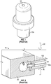
- FIGS. 1 shows an insert 50a, known in the art, for an evaporator assembly 55 ( FIG. 2 ).
- An insert-passage 62 is located at the center of the insert 50a.
- the evaporator assembly 55 includes a header 60 that defines a plurality of outlet ports generally referred to as 70, one of which 70a is shown in a cross section.
- An evaporator body 85 includes a plurality of evaporator passages generally referred to as 80, one 80a of which is illustrated in cross section.
- the evaporator passages 80 are generally parallel to one another in the evaporator body 85.
- a plurality of inserts generally referred to as 50 are disposed in respective ones of the plurality of outlet ports 70.
- One insert 50a which is the insert 50a of FIG. 1 , is illustrated in cross section.
- the respective ones of the plurality of outlet ports 70 may fluidly connect to respective ones of the plurality of evaporator passages 80.
- Heat energy 90 may be applied to either side or both sides of the evaporator body 85.
- the plurality of inserts 50 are commonly used to create desired back pressure at the entrance of the plurality of evaporator passages 80.
- the flow lines 95 illustrated in FIG. 2 indicate the fluid flow direction through the insert-passage 62 and inside the evaporator passage 80a in a microgravity environment, such as in an aerospace application.
- Undisturbed fluid may flow mostly in a straight line without contacting a sidewall 100 of the evaporator passage 80a.
- the fluid phase of the working fluid should contact the sidewall 100 of the evaporator passage 80a along an entire length of the evaporator passage 80a. Otherwise, available heat along the full length of the sidewall 100 may remain in the evaporator body 85. This is inefficient and may result in damage to the evaporator body 85.
- the swirl generator 200a includes a swirl generator body 210 that extends along a body-center axis 216 between opposing ends (inlet and outlet ends) generally referred to as 218.
- the swirl generator body 210 is illustrated as being cylindrical though other shapes are within the scope of the disclosure.
- a curved outer boundary 220 is defined by an outer surface 230 of the swirl generator body 210 at the outlet end 218a of the swirl generator body 210.
- a center passage 250 having opposing ends (inlet and outlet ends) generally referred to as 260 is defined by the swirl generator body 210, and which extends along the body-center axis 216.
- the outlet end 260a of the center passage 250 is intermediate the opposing ends 218 of the swirl generator body 210.
- the inlet end 260b of the center passage 250 is disposed on the body-center axis 216.
- the center passage 250 identified herein may be formed at least initially, that is before additional passages (identified below) are fabricated in the swirl generator 200a, as blind hole.
- a blind hole refers to a hole that is reamed, drilled, or milled to a specified depth without breaking through to the other side of a workpiece.
- a swirl passage 270a is defined by the swirl generator body 210.
- the swirl passage 270a extends between the outlet end 260a of the center passage 250 and the curved outer boundary 220.
- the swirl passage 270a defines a swirl-passage axis 280 extending between a swirl passage inlet 290a and a swirl passage outlet 300a.
- the swirl passage inlet 290a is defined at the outlet end 260a of the center passage 250 and the swirl passage outlet 300a is defined on the curved outer boundary 220.
- the body-center axis 216 and the swirl-passage axis 280 are oriented at an angle 310, which may be an acute angle with respect to the body-center axis 216.
- the swirl passage 270a is designed to tangentially face the sidewall 100 of the evaporator passage 80a ( FIG. 4 ).
- a center passage diameter D1 is larger than a swirl passage diameter D2. This way, fluid is throttled through the swirl passage 270a from the center passage 250.
- the outer surface 320 of the swirl generator body 210 defines a flange 330 between the opposing ends 218 of the swirl generator body 210.
- the flange 330 partitions the swirl generator 200a into opposing sides generally referred to as 340.
- One side 340a of the swirl generator body 210 is between the flange 330 and the outlet end 218a of the swirl generator body 210.
- Another side 340b of the swirl generator body 210 is between the flange 330 and the inlet end 218b of the swirl generator body 210.
- the flange 330 is used, as indicated below, for seating of the swirl generator 200a between the header 60 and the evaporator body 85 in the outlet port 70a.
- An outer diameter DS1 of the swirl generator body 210 is larger on the one side 340a of the swirl generator body 210 than the diameter DS2 of the other side 340b of the swirl generator body 210.
- the configuration of the outer surface 320 of the swirl generator body 210 as indicated below, enables a proper fitting between the header 60, the swirl generator 200a and the evaporator body 85. However this configuration is not intended on limiting the relative sizing of the opposing sides 340 of the swirl generator body 210 relative to each other and the flange 330. In addition, in certain embodiments a flange 330 is not provided.
- the swirl generator 200a includes a plurality of swirl passages generally referred to as 270.
- the outlet end 260a of the center passage 250 defines a plurality of swirl passage inlets generally referred to as 290.
- the curved outer boundary 220 defines a plurality of swirl passage outlets generally referred to as 300.
- the outlet end 260a of the center passage 250 and the curved outer boundary 220 are each annular.
- the plurality of swirl passages 270 are circumferentially offset from one another and axially aligned with one another along the body-center axis 216.
- FIG. 4 shows an evaporator assembly 400 which is similar to the evaporator assembly 55a of FIG. 2 except as identified.
- the evaporator assembly 400 includes the header 60 that defines the plurality of outlet ports 70, one 70a of which is illustrated in cross section.
- the evaporator body 85 defines the plurality of evaporator passages 80, one of which 80a is illustrated in cross section.
- the plurality of outlet ports 70 are in fluid communication with respective ones of the plurality of evaporator passages 80. Heat can be applied to either side or both sides of the evaporator body 85.
- a plurality of swirl generators generally referred to as 200 are disposed in respective ones of the plurality of outlet ports 70.
- One swirl generator 200a which is the swirl generator 200a of FIGS. 3a and 3b , is illustrated in cross section. Through the plurality of swirl generators 200, the respective ones of the plurality of outlet ports 70 may fluidly connect to respective ones of the plurality of evaporator passages 80.
- the outlet port 70a in the header includes one portion 410 that is sized to receive the evaporator body 85. As indicated, the one side 340a of the swirl generator body 210 is received within the evaporator passage 80a. Another portion 420 of the outlet port 70a is sized to receive the other side 340b of the swirl generator body 210. An intermediate portion 430 of the outlet port 70a is sized to receive the flange 330 of the swirl generator 200a. The flange 330 prevents movement of the swirl generator 200a relative to the header 60 and the evaporator body 85.
- the evaporator passage 80a has a larger flow area than the one portion 410 of the outlet port 70a.
- the one side 340a of the swirl generator body 210 has a larger diameter than the other side 340b of the swirl generator body 210.
- this configuration is not intended on limiting the relative sizing of the opposing sides 340 of the swirl generator body 210.
- the curved outer boundary 220 of the swirl generator body 210 is adjacent to and at least partially faces the sidewall 100 of the evaporator passage 80a.
- This configuration enables the creation of a swirl flow 440 within the evaporator passage 80a. That is, after flowing into the swirl generator 200a, the single-phase liquid or two-phase fluid is guided into the plurality of swirl passages 270. The fluid exits the swirl generator 200a along a tangential direction relative to the flow path 450 of the fluid and with the angle 310 with respect to the centerline 460 of the evaporator passage 80a.
- the fluid exiting the swirl generator 200a will have both an axial velocity component AV and a radial velocity component RV relative to the geometry of the evaporator passage 80a.
- the radial flow velocity component RV moves the fluid towards a sidewall 100 of the evaporator passage 80a and the axial velocity component AV moves the fluid downstream in the evaporator passage 80a.
- the swirl generator 200a may be used in different types of evaporator assemblies for example with evaporator bodies having different flow passage geometries.
- the disclosed embodiments provide an efficient evaporation process inside an evaporator and result in a more uniform temperature distribution on outside surface of the evaporator.
- a method for evaporating a single-phase liquid or two-phase fluid with the evaporator assembly 400.
- the method includes directing a single-phase liquid or two-phase fluid into the header 60.
- Block 520 shows that the method includes directing the fluid into the center passage 250 of the swirl generator 200a from the outlet port 70a of the header 60.
- the method includes directing the fluid into the swirl passage 270a defined by the swirl generator 200a.
- the method includes directing the fluid into the evaporator passage 75a of the evaporator body 85, from the swirl passage 270a.
- the method includes forming a swirling fluid stream as the fluid exits the swirl passage 270a. From this configuration the fluid moves towards the sidewall 100 of the evaporator passage 80a and moves downstream along the evaporator passage 80a.
Landscapes
- Engineering & Computer Science (AREA)
- Physics & Mathematics (AREA)
- Thermal Sciences (AREA)
- Mechanical Engineering (AREA)
- General Engineering & Computer Science (AREA)
- Fluid Mechanics (AREA)
- Chemical & Material Sciences (AREA)
- Chemical Kinetics & Catalysis (AREA)
- Geometry (AREA)
- Heat-Exchange Devices With Radiators And Conduit Assemblies (AREA)
Abstract
Description
- The embodiments herein relate to an evaporator for evaporating a single-phase liquid or two-phase fluid in a refrigerant system and more specifically to a swirl generator for the evaporator.
- A distributor, e.g., a header, in refrigeration systems receives single-phase liquid or two-phase refrigerant flow and divides it equally to provide uniform feed to all passages of an evaporator. Thus each passage of an evaporator in a refrigeration system should have an equal fluid mass flow rate of refrigerant in order for the refrigeration system to effectively to use the evaporator. In addition, the distributor is used to reduce flow from a larger area within the distributor to a smaller area in the individual evaporator paths. Under adverse gravity conditions of the type encountered in aerospace applications, characteristics of the flow dynamics into the evaporator passages from the distributor may result in reduced contact between the working fluid and the evaporator. This may reduce effectiveness of the system.
- Disclosed is a swirl generator for an evaporator, comprising: a swirl generator body that extends along a body-center axis between opposing inlet and outlet ends, the swirl generator body including a fluid inlet at the inlet end, wherein the swirl generator body includes an outer surface that, at that the outlet end, defines an outlet region that includes a curved outer boundary that forms a convex curve that extends radially inward from an outer diameter surface of the body to an outer axial surface of the body; a center passage formed within the swirl generator body that extends from the inlet towards the outlet along the body-center axis; and a swirl passage formed at the outlet end of the swirl generator body, the swirl passage extending between the center passage and the curved outer boundary along a swirl passage axis such that a fluid entering the center passage from the inlet end exits the swirl generator body at the curved outer boundary, wherein the swirl passage axis forms an acute angle with the body-center axis.
- In addition to one or more of the above disclosed aspects or as an alternate the outer surface of the swirl generator body is cylindrical.
- In addition to one or more of the above disclosed aspects or as an alternate the curved outer boundary is rounded.
- In addition to one or more of the above disclosed aspects or as an alternate a center passage diameter is larger than a swirl passage diameter.
- In addition to one or more of the above disclosed aspects or as an alternate the swirl generator body forms a plurality of swirl passages that are circumferentially offset from one another and axially aligned with one another.
- In addition to one or more of the above disclosed aspects or as an alternate the outer surface of the swirl generator body defines a flange between the opposing ends of the swirl generator body.
- In addition to one or more of the above disclosed aspects or as an alternate an outer diameter of the swirl generator body is larger on one side of the swirl generator body than another side of the swirl generator body.
- Further disclosed is an evaporator assembly including: a header that defines an outlet port; an evaporator body that defines an evaporator passage in fluid communication with the outlet port; and a swirl generator, comprising: a swirl generator body that extends along a body-center axis between opposing inlet and outlet ends, the swirl generator body including a fluid inlet at the inlet end, wherein the swirl generator body includes an outer surface that, at that the outlet end, defines an outlet region that includes a curved outer boundary that forms a convex curve that extends radially inward from an outer diameter surface of the body to an outer axial surface of the body; a center passage formed within the swirl generator body that extends from the inlet towards the outlet along the body-center axis; and a swirl passage formed at the outlet end of the swirl generator body, the swirl passage extending between the center passage and the curved outer boundary along a swirl passage axis such that a fluid entering the center passage from the inlet end exits the swirl generator body at the curved outer boundary, wherein the swirl passage axis forms an acute angle with the body-center axis.
- In addition to one or more of the above disclosed aspects or as an alternate the outlet port includes: a one portion that is sized to receive the evaporator body, wherein the one side of the swirl generator body is received within the evaporator passage; another portion that is sized to receive the other side of the swirl generator body; and an intermediate portion that is sized to receive the flange of the swirl generator.
- In addition to one or more of the above disclosed aspects or as an alternate the curved outer boundary of the swirl generator body is adj acent to and at least partially faces a sidewall of the evaporator passage.
- In addition to one or more of the above disclosed aspects or as an alternate the evaporator assembly further includes: a plurality of outlet ports formed within the header; a plurality of evaporator passages formed within the evaporator body in fluid communication with respective ones of the plurality of outlet ports, a plurality of swirl generators fluidly connected between the plurality of outlet ports and respective ones of the plurality of evaporator passages.
- In addition to one or more of the above disclosed aspects or as an alternate the plurality of evaporator passages each have a grooved inner geometry or a smooth inner geometry.
- Further disclosed is a method comprising: directing a fluid into a center passage of a swirl generator from an outlet port of an header; directing the fluid into a swirl passage defined by the swirl generator; directing the fluid into an evaporator passage of an evaporator body from the swirl passage; and forming a swirling fluid stream from the swirl passage, in which the fluid moves towards a sidewall of the evaporator passage and moves downstream along the evaporator passage.
- In addition to one or more of the above disclosed aspects or as an alternate, directing the fluid into the center passage of the swirl generator includes directing the fluid into the center passage of respective ones of a plurality of swirl generators from respective ones of a plurality of outlet ports of the header.
- The present disclosure is illustrated by way of example and not limited in the accompanying figures in which like reference numerals indicate similar elements.
-
FIG. 1 is an isometric view of a prior art insert for an evaporator; -
FIG. 2 is a cross sectional view of an evaporator equipped with the insert ofFIG. 1 ; -
FIG. 3a is an isometric view of a swirl generator, according to an embodiment; -
FIG. 3b is a cross-sectional view of the swirl generator ofFIG. 3a taken along lines A-A inFIG. 3a , according to an embodiment; -
FIG. 4 is a cross sectional view of an evaporator equipped with the swirl generator at the evaporator inlet; -
FIGS. 5a and 5b show different evaporator flow passage surface, including a smooth surface and a grooved surface, respectively; and -
FIG. 6 is a flowchart showing a method of evaporating a single-phase liquid or two-phase fluid with an evaporator assembly. - Aspects of the disclosed embodiments will now be addressed with reference to the figures. Aspects in any one figure is equally applicable to any other figure unless otherwise indicated. Aspects illustrated in the figures are for purposes of supporting the disclosure and are not in any way intended on limiting the scope of the disclosed embodiments. Any sequence of numbering in the figures is for reference purposes only.
- In a thermal management system, the evaporator utilizes the latent heat of the fluid to absorb waste heat from the heat source. After vaporizing, a vapor phase of the working fluid occupies most of the space inside the evaporator. In the case of removing heat from a large footprint area, the evaporator will be designed to have multiple parallel flow passages which allows the working fluid to be vaporized with reasonable pressure drop and temperature uniformity. In a parallel flow passage design, a flow distribution is a factor determining the overall evaporator performance.
-
FIGS. 1 shows aninsert 50a, known in the art, for an evaporator assembly 55 (FIG. 2 ). An insert-passage 62 is located at the center of theinsert 50a. InFIG. 2 , theevaporator assembly 55 includes aheader 60 that defines a plurality of outlet ports generally referred to as 70, one of which 70a is shown in a cross section. Anevaporator body 85 includes a plurality of evaporator passages generally referred to as 80, one 80a of which is illustrated in cross section. The evaporator passages 80 are generally parallel to one another in theevaporator body 85. - A plurality of inserts generally referred to as 50 are disposed in respective ones of the plurality of
outlet ports 70. Oneinsert 50a, which is theinsert 50a ofFIG. 1 , is illustrated in cross section. Through the plurality of inserts 50, the respective ones of the plurality ofoutlet ports 70 may fluidly connect to respective ones of the plurality of evaporator passages 80.Heat energy 90 may be applied to either side or both sides of theevaporator body 85. To achieve uniform flow distribution in the parallel flow passages design, the plurality of inserts 50 are commonly used to create desired back pressure at the entrance of the plurality of evaporator passages 80. - The
flow lines 95 illustrated inFIG. 2 indicate the fluid flow direction through the insert-passage 62 and inside theevaporator passage 80a in a microgravity environment, such as in an aerospace application. Undisturbed fluid may flow mostly in a straight line without contacting asidewall 100 of theevaporator passage 80a. In order to have an efficient operation, the fluid phase of the working fluid should contact thesidewall 100 of theevaporator passage 80a along an entire length of theevaporator passage 80a. Otherwise, available heat along the full length of thesidewall 100 may remain in theevaporator body 85. This is inefficient and may result in damage to theevaporator body 85. - In view of the above identified concerns, turning to
FIGS. 3a and 3b aswirl generator 200a is disclosed herein. Theswirl generator 200a includes aswirl generator body 210 that extends along a body-center axis 216 between opposing ends (inlet and outlet ends) generally referred to as 218. Theswirl generator body 210 is illustrated as being cylindrical though other shapes are within the scope of the disclosure. A curvedouter boundary 220 is defined by an outer surface 230 of theswirl generator body 210 at theoutlet end 218a of theswirl generator body 210. - The curved
outer boundary 220 is illustrated as a rounded edge, such as a fillet, though other shapes are within the scope of the disclosure. Acenter passage 250 having opposing ends (inlet and outlet ends) generally referred to as 260 is defined by theswirl generator body 210, and which extends along the body-center axis 216. The outlet end 260a of thecenter passage 250 is intermediate the opposing ends 218 of theswirl generator body 210. Theinlet end 260b of thecenter passage 250 is disposed on the body-center axis 216. Thecenter passage 250 identified herein may be formed at least initially, that is before additional passages (identified below) are fabricated in theswirl generator 200a, as blind hole. As would be understood by one of ordinary skill, a blind hole refers to a hole that is reamed, drilled, or milled to a specified depth without breaking through to the other side of a workpiece. - A swirl passage 270a is defined by the
swirl generator body 210. The swirl passage 270a extends between the outlet end 260a of thecenter passage 250 and the curvedouter boundary 220. The swirl passage 270a defines a swirl-passage axis 280 extending between aswirl passage inlet 290a and aswirl passage outlet 300a. Theswirl passage inlet 290a is defined at the outlet end 260a of thecenter passage 250 and theswirl passage outlet 300a is defined on the curvedouter boundary 220. - The body-
center axis 216 and the swirl-passage axis 280 are oriented at anangle 310, which may be an acute angle with respect to the body-center axis 216. Thus, as will be explained below, the swirl passage 270a is designed to tangentially face thesidewall 100 of theevaporator passage 80a (FIG. 4 ). A center passage diameter D1 is larger than a swirl passage diameter D2. This way, fluid is throttled through the swirl passage 270a from thecenter passage 250. - The
outer surface 320 of theswirl generator body 210 defines aflange 330 between the opposing ends 218 of theswirl generator body 210. Theflange 330 partitions theswirl generator 200a into opposing sides generally referred to as 340. Oneside 340a of theswirl generator body 210 is between theflange 330 and theoutlet end 218a of theswirl generator body 210. Anotherside 340b of theswirl generator body 210 is between theflange 330 and the inlet end 218b of theswirl generator body 210. Theflange 330 is used, as indicated below, for seating of theswirl generator 200a between theheader 60 and theevaporator body 85 in theoutlet port 70a. An outer diameter DS1 of theswirl generator body 210 is larger on the oneside 340a of theswirl generator body 210 than the diameter DS2 of theother side 340b of theswirl generator body 210. The configuration of theouter surface 320 of theswirl generator body 210, as indicated below, enables a proper fitting between theheader 60, theswirl generator 200a and theevaporator body 85. However this configuration is not intended on limiting the relative sizing of the opposing sides 340 of theswirl generator body 210 relative to each other and theflange 330. In addition, in certain embodiments aflange 330 is not provided. - As illustrated, the
swirl generator 200a includes a plurality of swirl passages generally referred to as 270. The outlet end 260a of thecenter passage 250 defines a plurality of swirl passage inlets generally referred to as 290. The curvedouter boundary 220 defines a plurality of swirl passage outlets generally referred to as 300. As illustrated, the outlet end 260a of thecenter passage 250 and the curvedouter boundary 220 are each annular. With the illustrated configuration, the plurality ofswirl passages 270 are circumferentially offset from one another and axially aligned with one another along the body-center axis 216. -
FIG. 4 shows anevaporator assembly 400 which is similar to the evaporator assembly 55a ofFIG. 2 except as identified. Theevaporator assembly 400 includes theheader 60 that defines the plurality ofoutlet ports 70, one 70a of which is illustrated in cross section. Theevaporator body 85 defines the plurality of evaporator passages 80, one of which 80a is illustrated in cross section. The plurality ofoutlet ports 70 are in fluid communication with respective ones of the plurality of evaporator passages 80. Heat can be applied to either side or both sides of theevaporator body 85. A plurality of swirl generators generally referred to as 200 are disposed in respective ones of the plurality ofoutlet ports 70. Oneswirl generator 200a, which is theswirl generator 200a ofFIGS. 3a and 3b , is illustrated in cross section. Through the plurality of swirl generators 200, the respective ones of the plurality ofoutlet ports 70 may fluidly connect to respective ones of the plurality of evaporator passages 80. - The
outlet port 70a in the header includes oneportion 410 that is sized to receive theevaporator body 85. As indicated, the oneside 340a of theswirl generator body 210 is received within theevaporator passage 80a. Anotherportion 420 of theoutlet port 70a is sized to receive theother side 340b of theswirl generator body 210. An intermediate portion 430 of theoutlet port 70a is sized to receive theflange 330 of theswirl generator 200a. Theflange 330 prevents movement of theswirl generator 200a relative to theheader 60 and theevaporator body 85. Theevaporator passage 80a has a larger flow area than the oneportion 410 of theoutlet port 70a. Therefore, as indicated, the oneside 340a of theswirl generator body 210 has a larger diameter than theother side 340b of theswirl generator body 210. However, as indicated, this configuration is not intended on limiting the relative sizing of the opposing sides 340 of theswirl generator body 210. - The curved
outer boundary 220 of theswirl generator body 210, and thus theswirl passage outlet 300a, is adjacent to and at least partially faces thesidewall 100 of theevaporator passage 80a. This configuration enables the creation of aswirl flow 440 within theevaporator passage 80a. That is, after flowing into theswirl generator 200a, the single-phase liquid or two-phase fluid is guided into the plurality ofswirl passages 270. The fluid exits theswirl generator 200a along a tangential direction relative to theflow path 450 of the fluid and with theangle 310 with respect to thecenterline 460 of theevaporator passage 80a. Due to the orientation of the plurality ofswirl passages 270, the fluid exiting theswirl generator 200a will have both an axial velocity component AV and a radial velocity component RV relative to the geometry of theevaporator passage 80a. Once inside theevaporator passage 80a, the radial flow velocity component RV moves the fluid towards asidewall 100 of theevaporator passage 80a and the axial velocity component AV moves the fluid downstream in theevaporator passage 80a. - The
swirl generator 200a may be used in different types of evaporator assemblies for example with evaporator bodies having different flow passage geometries. Two exemplaryevaporator bodies FIGS. 5a and 5b . It should be noted that a variety of flow passage geometries may be implemented and fit within the scope of the present disclosure. - The disclosed embodiments provide an efficient evaporation process inside an evaporator and result in a more uniform temperature distribution on outside surface of the evaporator.
- Turning to
FIG. 6 , a method is disclosed for evaporating a single-phase liquid or two-phase fluid with theevaporator assembly 400. As show inblock 510 the method includes directing a single-phase liquid or two-phase fluid into theheader 60.Block 520 shows that the method includes directing the fluid into thecenter passage 250 of theswirl generator 200a from theoutlet port 70a of theheader 60. As shown inblock 530 the method includes directing the fluid into the swirl passage 270a defined by theswirl generator 200a. - As shown in
block 540 the method includes directing the fluid into the evaporator passage 75a of theevaporator body 85, from the swirl passage 270a. As shown inblock 550 the method includes forming a swirling fluid stream as the fluid exits the swirl passage 270a. From this configuration the fluid moves towards thesidewall 100 of theevaporator passage 80a and moves downstream along theevaporator passage 80a. - The terminology used herein is for the purpose of describing particular embodiments only and is not intended to be limiting of the present disclosure. As used herein, the singular forms "a", "an" and "the" are intended to include the plural forms as well, unless the context clearly indicates otherwise. It will be further understood that the terms "comprises" and/or "comprising," when used in this specification, specify the presence of stated features, integers, steps, operations, elements, and/or components, but do not preclude the presence or addition of one or more other features, integers, steps, operations, element components, and/or groups thereof.
- Those of skill in the art will appreciate that various example embodiments are shown and described herein, each having certain features in the particular embodiments, but the present disclosure is not thus limited. Rather, the present disclosure can be modified to incorporate any number of variations, alterations, substitutions, combinations, sub-combinations, or equivalent arrangements not heretofore described, but which are commensurate with the scope of the present disclosure. Additionally, while various embodiments of the present disclosure have been described, it is to be understood that aspects of the present disclosure may include only some of the described embodiments. Accordingly, the present disclosure is not to be seen as limited by the foregoing description, but is only limited by the scope of the appended claims.
Claims (14)
- A swirl generator (200a) for an evaporator, comprising:a swirl generator body (210) that extends along a body-center axis (216) between opposing inlet and outlet ends (218), the swirl generator body including a fluid inlet at the inlet end,wherein the swirl generator body includes an outer surface (320) that, at that the outlet end, defines an outlet region that includes a curved outer boundary (220) that forms a convex curve that extends radially inward from an outer diameter surface of the body to an outer axial surface of the body;a center passage (250) formed within the swirl generator body that extends from the inlet towards the outlet along the body-center axis; anda swirl passage (270a) formed at the outlet end of the swirl generator body,the swirl passage extending between the center passage and the curved outer boundary along a swirl passage axis such that a fluid entering the center passage from the inlet end exits the swirl generator body at the curved outer boundary, wherein the swirl passage axis forms an acute angle (310) with the body-center axis.
- The swirl generator of claim 1, wherein the outer surface of the swirl generator body is cylindrical.
- The swirl generator of any preceding claim, wherein the curved outer boundary is rounded.
- The swirl generator of any preceding claim, wherein a center passage diameter (D1) is larger than a swirl passage diameter (D2).
- The swirl generator of any preceding claim, wherein the swirl generator body forms a plurality of swirl passages (270) that are circumferentially offset from one another and axially aligned with one another.
- The swirl generator of any preceding claim, wherein the outer surface of the swirl generator body defines a flange (330) between the opposing ends of the swirl generator body.
- The swirl generator of any preceding claim, wherein an outer diameter of the swirl generator body is larger on one side of the swirl generator body than another side of the swirl generator body.
- An evaporator assembly (400) including:a header (60) that defines an outlet port (70);an evaporator body (85) that defines an evaporator passage (80) in fluid communication with the outlet port; andthe swirl generator (200a) of any preceding claim.
- The evaporator assembly of claim 8, wherein an outer diameter of the swirl generator body is larger on one side of the swirl generator body than another side of the swirl generator body; and
wherein the outlet port includes:a one portion (410) that is sized to receive the evaporator body, wherein the one side of the swirl generator body is received within the evaporator passage;another portion (420) that is sized to receive the other side (340b) of the swirl generator body; andan intermediate portion (430) that is sized to receive the flange (330) of the swirl generator. - The evaporator assembly of claim 8 or 9, wherein the curved outer boundary of the swirl generator body is adjacent to and at least partially faces a sidewall of the evaporator passage.
- The evaporator assembly of claim 8, 9 or 10, further including:a plurality of outlet ports (70) formed within the header;a plurality of evaporator passages (80) formed within the evaporator body in fluid communication with respective ones of the plurality of outlet ports,a plurality of swirl generators (200) fluidly connected between the plurality of outlet ports and respective ones of the plurality of evaporator passages.
- The evaporator assembly of claim 11, wherein the plurality of evaporator passages each have a grooved inner geometry or a smooth inner geometry.
- A method comprising:directing (520) a fluid into a center passage (250) of a swirl generator (200a) from an outlet port (70) of a header (60);directing (530) the fluid into a swirl passage (270a) defined by the swirl generator;directing (540) the fluid into an evaporator passage (80) of an evaporator body from the swirl passage; andforming (550) a swirling fluid stream from the swirl passage, in which the fluid moves towards a sidewall of the evaporator passage and moves downstream along the evaporator passage.
- The method of claim 13, wherein directing the fluid into the center passage of the swirl generator includes directing the fluid into the center passage of respective ones of a plurality of swirl generators from respective ones of a plurality of outlet ports of the header.
Applications Claiming Priority (1)
| Application Number | Priority Date | Filing Date | Title |
|---|---|---|---|
| US16/679,909 US11439923B2 (en) | 2019-11-11 | 2019-11-11 | Swirl generator |
Publications (2)
| Publication Number | Publication Date |
|---|---|
| EP3819562A1 true EP3819562A1 (en) | 2021-05-12 |
| EP3819562B1 EP3819562B1 (en) | 2024-09-18 |
Family
ID=73043188
Family Applications (1)
| Application Number | Title | Priority Date | Filing Date |
|---|---|---|---|
| EP20205193.4A Active EP3819562B1 (en) | 2019-11-11 | 2020-11-02 | Evaporator comprising a swirl generator, and associated method |
Country Status (2)
| Country | Link |
|---|---|
| US (1) | US11439923B2 (en) |
| EP (1) | EP3819562B1 (en) |
Families Citing this family (1)
| Publication number | Priority date | Publication date | Assignee | Title |
|---|---|---|---|---|
| US11718423B2 (en) * | 2021-12-17 | 2023-08-08 | Hamilton Sundstrand Corporation | Condensing heat exchanger with flow restricting inserts between the condenser element and the outlet header |
Citations (3)
| Publication number | Priority date | Publication date | Assignee | Title |
|---|---|---|---|---|
| WO2005007297A1 (en) * | 2003-07-16 | 2005-01-27 | Mango Martini Pty Ltd | Movement modification of feed streams in separation apparatus |
| CN103267391A (en) * | 2013-05-27 | 2013-08-28 | 东南大学 | Liquid uniform distribution component of dry type evaporator |
| CN103423923A (en) * | 2013-08-21 | 2013-12-04 | 南京金典制冷实业有限公司 | Flow equalizing distributor used in tube header of dry shell and tube evaporator |
Family Cites Families (13)
| Publication number | Priority date | Publication date | Assignee | Title |
|---|---|---|---|---|
| US1184936A (en) * | 1914-09-05 | 1916-05-30 | George C Huber | Flue-protector for steam-boilers. |
| US3016067A (en) * | 1960-08-11 | 1962-01-09 | Henry Vogt Machine Company | Liquid distributing device |
| US4087050A (en) * | 1975-09-18 | 1978-05-02 | Ishikawajima-Harima Jukogyo Kabushiki Kaisha | Swirl type pressure fuel atomizer |
| CA1082427A (en) * | 1977-09-01 | 1980-07-29 | Hassan A. Hamza | Method and an apparatus for intimately contacting a substance in fluid form with a liquid |
| US4248296A (en) * | 1979-08-07 | 1981-02-03 | Resources Conservation Company | Fluid distributor for condenser tubes |
| US5059226A (en) | 1989-10-27 | 1991-10-22 | Sundstrand Corporation | Centrifugal two-phase flow distributor |
| AUPP624298A0 (en) * | 1998-09-30 | 1998-10-22 | Alcos Technologies Pty Ltd | Cyclonic evaporator |
| WO2008010237A1 (en) | 2006-07-19 | 2008-01-24 | Spray Engineering Devices Limited | Improved distributor for falling film evaporator |
| JP5182246B2 (en) | 2009-07-27 | 2013-04-17 | 株式会社Ihi | Condenser for microgravity environment |
| JP6384374B2 (en) | 2015-03-23 | 2018-09-05 | 株式会社デンソー | Ejector refrigeration cycle |
| US20180161793A1 (en) * | 2016-10-07 | 2018-06-14 | Engineering & Scientific Innovations, Inc. | Smart multi-port fluid delivery system |
| US10888885B2 (en) * | 2018-11-15 | 2021-01-12 | Caterpillar Inc. | Reductant nozzle with swirling spray pattern |
| US11320216B2 (en) * | 2020-01-29 | 2022-05-03 | Hamilton Sundstrand Corporation | Insert for evaporator header |
-
2019
- 2019-11-11 US US16/679,909 patent/US11439923B2/en active Active
-
2020
- 2020-11-02 EP EP20205193.4A patent/EP3819562B1/en active Active
Patent Citations (3)
| Publication number | Priority date | Publication date | Assignee | Title |
|---|---|---|---|---|
| WO2005007297A1 (en) * | 2003-07-16 | 2005-01-27 | Mango Martini Pty Ltd | Movement modification of feed streams in separation apparatus |
| CN103267391A (en) * | 2013-05-27 | 2013-08-28 | 东南大学 | Liquid uniform distribution component of dry type evaporator |
| CN103423923A (en) * | 2013-08-21 | 2013-12-04 | 南京金典制冷实业有限公司 | Flow equalizing distributor used in tube header of dry shell and tube evaporator |
Also Published As
| Publication number | Publication date |
|---|---|
| US11439923B2 (en) | 2022-09-13 |
| EP3819562B1 (en) | 2024-09-18 |
| US20210138358A1 (en) | 2021-05-13 |
Similar Documents
| Publication | Publication Date | Title |
|---|---|---|
| US11692780B2 (en) | Heat exchangers | |
| US10137549B2 (en) | Milling cutter with lubrication conduits | |
| US11788803B2 (en) | Insert for evaporator header | |
| US4543802A (en) | Evaporating apparatus | |
| RU2697120C2 (en) | Rotating cartridge with lubricant-coolant grooves system | |
| EP3819562B1 (en) | Evaporator comprising a swirl generator, and associated method | |
| EP3000972B1 (en) | Turbine blade cooling structure | |
| CN110242369A (en) | Steam turbine installation | |
| EP3070419A1 (en) | Heat exchanger distributor swirl vane | |
| BR102021009461A2 (en) | IMPROVED DESCALING NOZZLE ASSEMBLY | |
| EP3951301B1 (en) | Heat exchanger and refrigeration cycle device | |
| EP4177560B1 (en) | Integrally formed flow distributor for fluid manifold | |
| WO2016188903A1 (en) | Cutter head | |
| EP3859258B1 (en) | Evaporator with grooved channels | |
| EP3150954B1 (en) | Heat transfer tubes | |
| EP3859259A1 (en) | Evaporator with grooved channels | |
| US11718423B2 (en) | Condensing heat exchanger with flow restricting inserts between the condenser element and the outlet header | |
| EP3444554B1 (en) | Heat exchanger assembly | |
| US20250290698A1 (en) | Grooved flow channel with porous insert for space radiator condensing | |
| WO2018211136A1 (en) | Phase separator comprising a flow disruptor | |
| TWI667097B (en) | End water outlet clamp | |
| JP2001041609A (en) | Refrigerant distributor for air-conditioning heat exchanger |
Legal Events
| Date | Code | Title | Description |
|---|---|---|---|
| PUAI | Public reference made under article 153(3) epc to a published international application that has entered the european phase |
Free format text: ORIGINAL CODE: 0009012 |
|
| STAA | Information on the status of an ep patent application or granted ep patent |
Free format text: STATUS: THE APPLICATION HAS BEEN PUBLISHED |
|
| AK | Designated contracting states |
Kind code of ref document: A1 Designated state(s): AL AT BE BG CH CY CZ DE DK EE ES FI FR GB GR HR HU IE IS IT LI LT LU LV MC MK MT NL NO PL PT RO RS SE SI SK SM TR |
|
| STAA | Information on the status of an ep patent application or granted ep patent |
Free format text: STATUS: REQUEST FOR EXAMINATION WAS MADE |
|
| 17P | Request for examination filed |
Effective date: 20211111 |
|
| RBV | Designated contracting states (corrected) |
Designated state(s): AL AT BE BG CH CY CZ DE DK EE ES FI FR GB GR HR HU IE IS IT LI LT LU LV MC MK MT NL NO PL PT RO RS SE SI SK SM TR |
|
| STAA | Information on the status of an ep patent application or granted ep patent |
Free format text: STATUS: EXAMINATION IS IN PROGRESS |
|
| 17Q | First examination report despatched |
Effective date: 20220926 |
|
| GRAP | Despatch of communication of intention to grant a patent |
Free format text: ORIGINAL CODE: EPIDOSNIGR1 |
|
| STAA | Information on the status of an ep patent application or granted ep patent |
Free format text: STATUS: GRANT OF PATENT IS INTENDED |
|
| RIC1 | Information provided on ipc code assigned before grant |
Ipc: F28D 21/00 20060101ALI20231117BHEP Ipc: F25B 41/385 20210101ALI20231117BHEP Ipc: F28F 9/02 20060101ALI20231117BHEP Ipc: F28F 1/40 20060101ALI20231117BHEP Ipc: F25B 39/02 20060101AFI20231117BHEP |
|
| INTG | Intention to grant announced |
Effective date: 20231204 |
|
| RIN1 | Information on inventor provided before grant (corrected) |
Inventor name: CHO, WEI-LIN |
|
| GRAJ | Information related to disapproval of communication of intention to grant by the applicant or resumption of examination proceedings by the epo deleted |
Free format text: ORIGINAL CODE: EPIDOSDIGR1 |
|
| STAA | Information on the status of an ep patent application or granted ep patent |
Free format text: STATUS: EXAMINATION IS IN PROGRESS |
|
| GRAP | Despatch of communication of intention to grant a patent |
Free format text: ORIGINAL CODE: EPIDOSNIGR1 |
|
| STAA | Information on the status of an ep patent application or granted ep patent |
Free format text: STATUS: GRANT OF PATENT IS INTENDED |
|
| INTC | Intention to grant announced (deleted) | ||
| INTG | Intention to grant announced |
Effective date: 20240419 |
|
| GRAS | Grant fee paid |
Free format text: ORIGINAL CODE: EPIDOSNIGR3 |
|
| GRAA | (expected) grant |
Free format text: ORIGINAL CODE: 0009210 |
|
| STAA | Information on the status of an ep patent application or granted ep patent |
Free format text: STATUS: THE PATENT HAS BEEN GRANTED |
|
| AK | Designated contracting states |
Kind code of ref document: B1 Designated state(s): AL AT BE BG CH CY CZ DE DK EE ES FI FR GB GR HR HU IE IS IT LI LT LU LV MC MK MT NL NO PL PT RO RS SE SI SK SM TR |
|
| REG | Reference to a national code |
Ref country code: GB Ref legal event code: FG4D |
|
| REG | Reference to a national code |
Ref country code: CH Ref legal event code: EP |
|
| REG | Reference to a national code |
Ref country code: DE Ref legal event code: R096 Ref document number: 602020037845 Country of ref document: DE |
|
| REG | Reference to a national code |
Ref country code: IE Ref legal event code: FG4D |
|
| REG | Reference to a national code |
Ref country code: LT Ref legal event code: MG9D |
|
| PG25 | Lapsed in a contracting state [announced via postgrant information from national office to epo] |
Ref country code: NO Free format text: LAPSE BECAUSE OF FAILURE TO SUBMIT A TRANSLATION OF THE DESCRIPTION OR TO PAY THE FEE WITHIN THE PRESCRIBED TIME-LIMIT Effective date: 20241218 |
|
| PG25 | Lapsed in a contracting state [announced via postgrant information from national office to epo] |
Ref country code: GR Free format text: LAPSE BECAUSE OF FAILURE TO SUBMIT A TRANSLATION OF THE DESCRIPTION OR TO PAY THE FEE WITHIN THE PRESCRIBED TIME-LIMIT Effective date: 20241219 Ref country code: FI Free format text: LAPSE BECAUSE OF FAILURE TO SUBMIT A TRANSLATION OF THE DESCRIPTION OR TO PAY THE FEE WITHIN THE PRESCRIBED TIME-LIMIT Effective date: 20240918 |
|
| PG25 | Lapsed in a contracting state [announced via postgrant information from national office to epo] |
Ref country code: BG Free format text: LAPSE BECAUSE OF FAILURE TO SUBMIT A TRANSLATION OF THE DESCRIPTION OR TO PAY THE FEE WITHIN THE PRESCRIBED TIME-LIMIT Effective date: 20240918 |
|
| PG25 | Lapsed in a contracting state [announced via postgrant information from national office to epo] |
Ref country code: LV Free format text: LAPSE BECAUSE OF FAILURE TO SUBMIT A TRANSLATION OF THE DESCRIPTION OR TO PAY THE FEE WITHIN THE PRESCRIBED TIME-LIMIT Effective date: 20240918 |
|
| PG25 | Lapsed in a contracting state [announced via postgrant information from national office to epo] |
Ref country code: HR Free format text: LAPSE BECAUSE OF FAILURE TO SUBMIT A TRANSLATION OF THE DESCRIPTION OR TO PAY THE FEE WITHIN THE PRESCRIBED TIME-LIMIT Effective date: 20240918 |
|
| REG | Reference to a national code |
Ref country code: NL Ref legal event code: MP Effective date: 20240918 |
|
| PG25 | Lapsed in a contracting state [announced via postgrant information from national office to epo] |
Ref country code: RS Free format text: LAPSE BECAUSE OF FAILURE TO SUBMIT A TRANSLATION OF THE DESCRIPTION OR TO PAY THE FEE WITHIN THE PRESCRIBED TIME-LIMIT Effective date: 20241218 |
|
| PG25 | Lapsed in a contracting state [announced via postgrant information from national office to epo] |
Ref country code: RS Free format text: LAPSE BECAUSE OF FAILURE TO SUBMIT A TRANSLATION OF THE DESCRIPTION OR TO PAY THE FEE WITHIN THE PRESCRIBED TIME-LIMIT Effective date: 20241218 Ref country code: NO Free format text: LAPSE BECAUSE OF FAILURE TO SUBMIT A TRANSLATION OF THE DESCRIPTION OR TO PAY THE FEE WITHIN THE PRESCRIBED TIME-LIMIT Effective date: 20241218 Ref country code: LV Free format text: LAPSE BECAUSE OF FAILURE TO SUBMIT A TRANSLATION OF THE DESCRIPTION OR TO PAY THE FEE WITHIN THE PRESCRIBED TIME-LIMIT Effective date: 20240918 Ref country code: HR Free format text: LAPSE BECAUSE OF FAILURE TO SUBMIT A TRANSLATION OF THE DESCRIPTION OR TO PAY THE FEE WITHIN THE PRESCRIBED TIME-LIMIT Effective date: 20240918 Ref country code: GR Free format text: LAPSE BECAUSE OF FAILURE TO SUBMIT A TRANSLATION OF THE DESCRIPTION OR TO PAY THE FEE WITHIN THE PRESCRIBED TIME-LIMIT Effective date: 20241219 Ref country code: FI Free format text: LAPSE BECAUSE OF FAILURE TO SUBMIT A TRANSLATION OF THE DESCRIPTION OR TO PAY THE FEE WITHIN THE PRESCRIBED TIME-LIMIT Effective date: 20240918 Ref country code: BG Free format text: LAPSE BECAUSE OF FAILURE TO SUBMIT A TRANSLATION OF THE DESCRIPTION OR TO PAY THE FEE WITHIN THE PRESCRIBED TIME-LIMIT Effective date: 20240918 |
|
| REG | Reference to a national code |
Ref country code: AT Ref legal event code: MK05 Ref document number: 1724999 Country of ref document: AT Kind code of ref document: T Effective date: 20240918 |
|
| PG25 | Lapsed in a contracting state [announced via postgrant information from national office to epo] |
Ref country code: NL Free format text: LAPSE BECAUSE OF FAILURE TO SUBMIT A TRANSLATION OF THE DESCRIPTION OR TO PAY THE FEE WITHIN THE PRESCRIBED TIME-LIMIT Effective date: 20240918 |
|
| PG25 | Lapsed in a contracting state [announced via postgrant information from national office to epo] |
Ref country code: IS Free format text: LAPSE BECAUSE OF FAILURE TO SUBMIT A TRANSLATION OF THE DESCRIPTION OR TO PAY THE FEE WITHIN THE PRESCRIBED TIME-LIMIT Effective date: 20250118 Ref country code: PT Free format text: LAPSE BECAUSE OF FAILURE TO SUBMIT A TRANSLATION OF THE DESCRIPTION OR TO PAY THE FEE WITHIN THE PRESCRIBED TIME-LIMIT Effective date: 20250120 |
|
| PG25 | Lapsed in a contracting state [announced via postgrant information from national office to epo] |
Ref country code: RO Free format text: LAPSE BECAUSE OF FAILURE TO SUBMIT A TRANSLATION OF THE DESCRIPTION OR TO PAY THE FEE WITHIN THE PRESCRIBED TIME-LIMIT Effective date: 20240918 Ref country code: SM Free format text: LAPSE BECAUSE OF FAILURE TO SUBMIT A TRANSLATION OF THE DESCRIPTION OR TO PAY THE FEE WITHIN THE PRESCRIBED TIME-LIMIT Effective date: 20240918 |
|
| PG25 | Lapsed in a contracting state [announced via postgrant information from national office to epo] |
Ref country code: ES Free format text: LAPSE BECAUSE OF FAILURE TO SUBMIT A TRANSLATION OF THE DESCRIPTION OR TO PAY THE FEE WITHIN THE PRESCRIBED TIME-LIMIT Effective date: 20240918 |
|
| PG25 | Lapsed in a contracting state [announced via postgrant information from national office to epo] |
Ref country code: EE Free format text: LAPSE BECAUSE OF FAILURE TO SUBMIT A TRANSLATION OF THE DESCRIPTION OR TO PAY THE FEE WITHIN THE PRESCRIBED TIME-LIMIT Effective date: 20240918 Ref country code: AT Free format text: LAPSE BECAUSE OF FAILURE TO SUBMIT A TRANSLATION OF THE DESCRIPTION OR TO PAY THE FEE WITHIN THE PRESCRIBED TIME-LIMIT Effective date: 20240918 |
|
| PG25 | Lapsed in a contracting state [announced via postgrant information from national office to epo] |
Ref country code: CZ Free format text: LAPSE BECAUSE OF FAILURE TO SUBMIT A TRANSLATION OF THE DESCRIPTION OR TO PAY THE FEE WITHIN THE PRESCRIBED TIME-LIMIT Effective date: 20240918 Ref country code: PL Free format text: LAPSE BECAUSE OF FAILURE TO SUBMIT A TRANSLATION OF THE DESCRIPTION OR TO PAY THE FEE WITHIN THE PRESCRIBED TIME-LIMIT Effective date: 20240918 |
|
| PG25 | Lapsed in a contracting state [announced via postgrant information from national office to epo] |
Ref country code: SK Free format text: LAPSE BECAUSE OF FAILURE TO SUBMIT A TRANSLATION OF THE DESCRIPTION OR TO PAY THE FEE WITHIN THE PRESCRIBED TIME-LIMIT Effective date: 20240918 Ref country code: IT Free format text: LAPSE BECAUSE OF FAILURE TO SUBMIT A TRANSLATION OF THE DESCRIPTION OR TO PAY THE FEE WITHIN THE PRESCRIBED TIME-LIMIT Effective date: 20240918 |
|
| REG | Reference to a national code |
Ref country code: DE Ref legal event code: R097 Ref document number: 602020037845 Country of ref document: DE |
|
| REG | Reference to a national code |
Ref country code: CH Ref legal event code: PL |
|
| PG25 | Lapsed in a contracting state [announced via postgrant information from national office to epo] |
Ref country code: MC Free format text: LAPSE BECAUSE OF FAILURE TO SUBMIT A TRANSLATION OF THE DESCRIPTION OR TO PAY THE FEE WITHIN THE PRESCRIBED TIME-LIMIT Effective date: 20240918 |
|
| PG25 | Lapsed in a contracting state [announced via postgrant information from national office to epo] |
Ref country code: DK Free format text: LAPSE BECAUSE OF FAILURE TO SUBMIT A TRANSLATION OF THE DESCRIPTION OR TO PAY THE FEE WITHIN THE PRESCRIBED TIME-LIMIT Effective date: 20240918 |
|
| PG25 | Lapsed in a contracting state [announced via postgrant information from national office to epo] |
Ref country code: LU Free format text: LAPSE BECAUSE OF NON-PAYMENT OF DUE FEES Effective date: 20241102 |
|
| REG | Reference to a national code |
Ref country code: CH Ref legal event code: PL |
|
| PG25 | Lapsed in a contracting state [announced via postgrant information from national office to epo] |
Ref country code: CH Free format text: LAPSE BECAUSE OF NON-PAYMENT OF DUE FEES Effective date: 20241130 |
|
| PLBE | No opposition filed within time limit |
Free format text: ORIGINAL CODE: 0009261 |
|
| STAA | Information on the status of an ep patent application or granted ep patent |
Free format text: STATUS: NO OPPOSITION FILED WITHIN TIME LIMIT |
|
| 26N | No opposition filed |
Effective date: 20250619 |
|
| REG | Reference to a national code |
Ref country code: BE Ref legal event code: MM Effective date: 20241130 |
|
| PG25 | Lapsed in a contracting state [announced via postgrant information from national office to epo] |
Ref country code: SE Free format text: LAPSE BECAUSE OF FAILURE TO SUBMIT A TRANSLATION OF THE DESCRIPTION OR TO PAY THE FEE WITHIN THE PRESCRIBED TIME-LIMIT Effective date: 20240918 |
|
| PG25 | Lapsed in a contracting state [announced via postgrant information from national office to epo] |
Ref country code: BE Free format text: LAPSE BECAUSE OF NON-PAYMENT OF DUE FEES Effective date: 20241130 |
|
| PG25 | Lapsed in a contracting state [announced via postgrant information from national office to epo] |
Ref country code: IE Free format text: LAPSE BECAUSE OF NON-PAYMENT OF DUE FEES Effective date: 20241102 |
|
| PGFP | Annual fee paid to national office [announced via postgrant information from national office to epo] |
Ref country code: DE Payment date: 20251022 Year of fee payment: 6 |
|
| PGFP | Annual fee paid to national office [announced via postgrant information from national office to epo] |
Ref country code: GB Payment date: 20251022 Year of fee payment: 6 |
|
| PGFP | Annual fee paid to national office [announced via postgrant information from national office to epo] |
Ref country code: FR Payment date: 20251023 Year of fee payment: 6 |
|
| PG25 | Lapsed in a contracting state [announced via postgrant information from national office to epo] |
Ref country code: HU Free format text: LAPSE BECAUSE OF FAILURE TO SUBMIT A TRANSLATION OF THE DESCRIPTION OR TO PAY THE FEE WITHIN THE PRESCRIBED TIME-LIMIT; INVALID AB INITIO Effective date: 20201102 |
|
| PG25 | Lapsed in a contracting state [announced via postgrant information from national office to epo] |
Ref country code: CY Free format text: LAPSE BECAUSE OF FAILURE TO SUBMIT A TRANSLATION OF THE DESCRIPTION OR TO PAY THE FEE WITHIN THE PRESCRIBED TIME-LIMIT; INVALID AB INITIO Effective date: 20201102 |