EP3819526A1 - Sealing device - Google Patents
Sealing device Download PDFInfo
- Publication number
- EP3819526A1 EP3819526A1 EP19830749.8A EP19830749A EP3819526A1 EP 3819526 A1 EP3819526 A1 EP 3819526A1 EP 19830749 A EP19830749 A EP 19830749A EP 3819526 A1 EP3819526 A1 EP 3819526A1
- Authority
- EP
- European Patent Office
- Prior art keywords
- lip
- foreign matter
- mat
- surface roughness
- lubricant
- Prior art date
- Legal status (The legal status is an assumption and is not a legal conclusion. Google has not performed a legal analysis and makes no representation as to the accuracy of the status listed.)
- Granted
Links
Images



Classifications
-
- F—MECHANICAL ENGINEERING; LIGHTING; HEATING; WEAPONS; BLASTING
- F16—ENGINEERING ELEMENTS AND UNITS; GENERAL MEASURES FOR PRODUCING AND MAINTAINING EFFECTIVE FUNCTIONING OF MACHINES OR INSTALLATIONS; THERMAL INSULATION IN GENERAL
- F16J—PISTONS; CYLINDERS; SEALINGS
- F16J15/00—Sealings
- F16J15/16—Sealings between relatively-moving surfaces
- F16J15/32—Sealings between relatively-moving surfaces with elastic sealings, e.g. O-rings
- F16J15/324—Arrangements for lubrication or cooling of the sealing itself
-
- F—MECHANICAL ENGINEERING; LIGHTING; HEATING; WEAPONS; BLASTING
- F16—ENGINEERING ELEMENTS AND UNITS; GENERAL MEASURES FOR PRODUCING AND MAINTAINING EFFECTIVE FUNCTIONING OF MACHINES OR INSTALLATIONS; THERMAL INSULATION IN GENERAL
- F16C—SHAFTS; FLEXIBLE SHAFTS; ELEMENTS OR CRANKSHAFT MECHANISMS; ROTARY BODIES OTHER THAN GEARING ELEMENTS; BEARINGS
- F16C19/00—Bearings with rolling contact, for exclusively rotary movement
- F16C19/02—Bearings with rolling contact, for exclusively rotary movement with bearing balls essentially of the same size in one or more circular rows
- F16C19/14—Bearings with rolling contact, for exclusively rotary movement with bearing balls essentially of the same size in one or more circular rows for both radial and axial load
- F16C19/18—Bearings with rolling contact, for exclusively rotary movement with bearing balls essentially of the same size in one or more circular rows for both radial and axial load with two or more rows of balls
- F16C19/181—Bearings with rolling contact, for exclusively rotary movement with bearing balls essentially of the same size in one or more circular rows for both radial and axial load with two or more rows of balls with angular contact
- F16C19/183—Bearings with rolling contact, for exclusively rotary movement with bearing balls essentially of the same size in one or more circular rows for both radial and axial load with two or more rows of balls with angular contact with two rows at opposite angles
- F16C19/184—Bearings with rolling contact, for exclusively rotary movement with bearing balls essentially of the same size in one or more circular rows for both radial and axial load with two or more rows of balls with angular contact with two rows at opposite angles in O-arrangement
- F16C19/185—Bearings with rolling contact, for exclusively rotary movement with bearing balls essentially of the same size in one or more circular rows for both radial and axial load with two or more rows of balls with angular contact with two rows at opposite angles in O-arrangement with two raceways provided integrally on a part other than a race ring, e.g. a shaft or housing
-
- F—MECHANICAL ENGINEERING; LIGHTING; HEATING; WEAPONS; BLASTING
- F16—ENGINEERING ELEMENTS AND UNITS; GENERAL MEASURES FOR PRODUCING AND MAINTAINING EFFECTIVE FUNCTIONING OF MACHINES OR INSTALLATIONS; THERMAL INSULATION IN GENERAL
- F16C—SHAFTS; FLEXIBLE SHAFTS; ELEMENTS OR CRANKSHAFT MECHANISMS; ROTARY BODIES OTHER THAN GEARING ELEMENTS; BEARINGS
- F16C33/00—Parts of bearings; Special methods for making bearings or parts thereof
- F16C33/72—Sealings
- F16C33/76—Sealings of ball or roller bearings
- F16C33/78—Sealings of ball or roller bearings with a diaphragm, disc, or ring, with or without resilient members
- F16C33/7803—Sealings of ball or roller bearings with a diaphragm, disc, or ring, with or without resilient members suited for particular types of rolling bearings
-
- F—MECHANICAL ENGINEERING; LIGHTING; HEATING; WEAPONS; BLASTING
- F16—ENGINEERING ELEMENTS AND UNITS; GENERAL MEASURES FOR PRODUCING AND MAINTAINING EFFECTIVE FUNCTIONING OF MACHINES OR INSTALLATIONS; THERMAL INSULATION IN GENERAL
- F16C—SHAFTS; FLEXIBLE SHAFTS; ELEMENTS OR CRANKSHAFT MECHANISMS; ROTARY BODIES OTHER THAN GEARING ELEMENTS; BEARINGS
- F16C33/00—Parts of bearings; Special methods for making bearings or parts thereof
- F16C33/72—Sealings
- F16C33/76—Sealings of ball or roller bearings
- F16C33/78—Sealings of ball or roller bearings with a diaphragm, disc, or ring, with or without resilient members
- F16C33/7869—Sealings of ball or roller bearings with a diaphragm, disc, or ring, with or without resilient members mounted with a cylindrical portion to the inner surface of the outer race and having a radial portion extending inward
- F16C33/7873—Sealings of ball or roller bearings with a diaphragm, disc, or ring, with or without resilient members mounted with a cylindrical portion to the inner surface of the outer race and having a radial portion extending inward with a single sealing ring of generally L-shaped cross-section
- F16C33/7876—Sealings of ball or roller bearings with a diaphragm, disc, or ring, with or without resilient members mounted with a cylindrical portion to the inner surface of the outer race and having a radial portion extending inward with a single sealing ring of generally L-shaped cross-section with sealing lips
-
- F—MECHANICAL ENGINEERING; LIGHTING; HEATING; WEAPONS; BLASTING
- F16—ENGINEERING ELEMENTS AND UNITS; GENERAL MEASURES FOR PRODUCING AND MAINTAINING EFFECTIVE FUNCTIONING OF MACHINES OR INSTALLATIONS; THERMAL INSULATION IN GENERAL
- F16J—PISTONS; CYLINDERS; SEALINGS
- F16J15/00—Sealings
- F16J15/16—Sealings between relatively-moving surfaces
- F16J15/32—Sealings between relatively-moving surfaces with elastic sealings, e.g. O-rings
- F16J15/3204—Sealings between relatively-moving surfaces with elastic sealings, e.g. O-rings with at least one lip
- F16J15/3232—Sealings between relatively-moving surfaces with elastic sealings, e.g. O-rings with at least one lip having two or more lips
Definitions
- the present disclosure relates to a sealing device provided to a hub bearing and the like.
- Car hub bearings are provided with sealing devices on both vehicle-body side and tire side. These sealing devices have a function of sealing annular gaps between inner rings and outer rings of the hub bearings. These sealing devices include a foreign matter lip for inhibiting ingress of foreign matter from outside, a grease lip for inhibiting leakage of grease, and a mid lip between these two lips. These lips are provided so as to be slidable relative to the inner ring or a slinger fixed to the inner ring.
- An object of the present disclosure is to provide a sealing device that can achieve both of torque reduction and sealing performance improvement.
- the present disclosure adopts the following means to achieve the object noted above.
- the present disclosure is a sealing device configured to seal an annular gap between a shaft and a housing that are rotatable relative to each other including:
- the lip that is not formed with mat-surface roughness has higher sealing performance.
- the sliding surface of the mid lip is provided with mat-surface roughness, torque due to sliding movements can be reduced.
- the "mat-surface roughness” refers to roughness that is actively formed on the sliding surface of the lip and do not include an intrinsic surface texture of the elastic material (such as rubber) that forms the lip or a surface texture resulting from an intrinsic roughness of metal molds for forming the main body. The same applies hereinafter.
- a sealing device configured to seal an annular gap between a shaft and a housing that are rotatable relative to each other including:
- the sliding surface with mat-surface roughness of the mid lip has the larger surface roughness than that of at least one of the sliding surface with mat-surface roughness of the foreign matter lip and the sliding surface with mat-surface roughness of the lubricant lip, it is possible to mitigate decrease in sealing performance of at least one of the foreign matter lip and the lubricant lip while reducing the sliding resistance of the mid lip.
- the present disclosure can achieve both of torque reduction and sealing performance improvement.
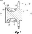
- FIG. 1 is a schematic cross-sectional view of the hub bearing according to this embodiment of the present disclosure.
- Fig. 1 shows a cross-sectional view of the hub bearing cut along a plane containing a rotation center axis of an inner ring.
- the hub bearing 10 includes an inner ring (shaft) 20 and an outer ring (housing) 30 that are rotatable relative to each other, and a plurality of balls 40 set between them.
- a tire (not shown) is secured to the inner ring 20, while the outer ring 30 is attached to a vehicle body.
- tire side (A) and vehicle-body side (B) respectively.
- An outward flange part 21 is provided to the tire side (A) of the inner ring 20 for attachment of the tire.
- Sealing devices 100 and 200 for sealing annular gaps between the inner ring 20 and the outer ring 30 are provided in order to inhibit ingress of foreign matter (mud water, dust and the like) from outside into the hub bearing 10 as well as to inhibit leakage of grease (G) as lubricant from inside.
- the sealing device 100 on the tire side (A) and the sealing device 200 on the vehicle-body side (B) may sometimes be called an outer seal and an inner seal, respectively.
- the sealing device 100 on the tire side (A) and the sealing device 200 on the vehicle-body side (B) can basically adopt a similar configuration.
- a seal lip that slides on an end face of a component that rotates with the inner ring 20 is provided to facilitate expulsion of foreign matter or the like to the outside by centrifugal force as the inner ring 20 rotates.
- a seal lip that slides on the outward flange part 21 can be provided to the sealing device 100 on the tire side (A)
- a slinger (annular member) 25 is provided in order to form a part corresponding to the outward flange part 21.
- the sealing device 200 on the vehicle-body side (B) and the sealing device 100 on the tire side (A) differ from each other in that the former commonly uses the slinger 25 while the latter does not use the slinger 25.
- Fig. 2 is a schematic cross-sectional view of the sealing device according to Embodiment 1 of the present disclosure.
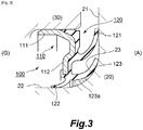
- Fig. 3 is an enlarged view of part of the schematic cross-sectional view of the hub bearing to which the sealing device according to Embodiment 1 of the present disclosure is applied.
- Fig. 2 and Fig. 3 show a cross-sectional view of the sealing device and others cut along a plane containing the rotation center axis of the inner ring.
- the sealing device 100 on the tire side (A) will be described as one example.
- the sealing device 100 is made up of a reinforcing ring 110 secured to the outer ring 30, and a main body 120 made of an elastic member (such as rubber) integrally provided to the reinforcing ring 110.
- the reinforcing ring 110 includes a substantially cylindrical part 111 fixed to an inner circumferential surface of the outer ring 30 by a press fit, and an inward flange part 112 extending from an end portion of the cylindrical part 111 (see Fig. 3 ).
- the main body 120 is integrally provided to the inward flange part 112.
- the main body 120 includes a foreign matter lip 121, a lubricant lip 122, and a mid lip 123.
- the foreign matter lip 121 is provided for inhibiting ingress of foreign matter.
- the foreign matter lip 121 extends radially outward and is slidable relative to the inner ring 20.
- the foreign matter lip 121 is slidable relative to an end face of the outward flange part 21 of the inner ring 20.
- the lubricant lip 122 is provided for inhibiting leakage of lubricant (grease (G)).
- the lubricant lip 122 extends radially inward and is slidable relative to an outer circumferential surface 22 of the inner ring 20.
- the mid lip 123 is provided to inhibit ingress of foreign matter as with the foreign matter lip 121 and serves to prevent foreign matter that the foreign matter lip 121 allows to pass through from accessing the balls 40.
- the mid lip 123 is provided between the foreign matter lip 121 and the lubricant lip 122 to extend radially outward and to be slidable relative to the inner ring 20.
- the mid lip 123 is slidable relative to a curved surface 23 between the outer circumferential surface 22 and the outward flange part 21 of the inner ring 20.
- a sliding surface of the mid lip 123 of the main body 120 is formed with mat-surface roughness 123a
- a sliding surface of the foreign matter lip 121 and a sliding surface of the lubricant lip 122 are not formed with mat-surface roughness.
- the mat-surface roughness 123a has randomly arranged peaks and valleys formed by a discharge process, blasting process or the like. While it is possible to form the peaks and valleys by directly processing the main body 120, productivity can be raised by providing mat-surface roughness on surfaces of metal molds for forming the main body 120.
- the mat-surface roughness 123a are designed so that the ten-point average roughness RzJIS (JIS B 0601:2001) is 2 ⁇ m or more and 40 ⁇ m or less.
- the mat-surface roughness 123a on the sliding surface of the mid lip 123 may be provided over the entire area of the mid lip 123 that can come into sliding contact with the inner ring 20.
- the entire inner circumferential surface of the mid lip 123 is provided with the mat-surface roughness 123a.
- the entire inner circumferential surface of the mid lip 123 may not be provided with the mat-surface roughness 123a.
- an area provided with mat-surface roughness 123a and an area not provided with the roughness may alternate in a circumferential direction.
- the mat-surface roughness refers to roughness that is actively formed on the sliding surface of the lip and do not include an intrinsic surface texture of the elastic material (such as rubber) that forms the lip or a surface texture resulting from an intrinsic roughness of metal molds for forming the main body. The same applies hereinafter.
- the sliding surface of the foreign matter lip 121 and the sliding surface of the lubricant lip 122 of the sealing device 100 according to this embodiment are not provided with mat-surface roughness, these lips can have better sealing performance.
- ingress of foreign matter such as mud water and dust from outside can be well inhibited by the foreign matter lip 121 with better sealing performance.
- Leakage of lubricant grey (G)
- air tightness on the bearing side where the balls 40 are provided
- the sealing performance of the mid lip 123 is lower than that of the foreign matter lip 121 and lubricant lip 122.
- the sealing device 100 as a whole can provide a satisfactorily high sealing performance even though the mid lip 123 has lower sealing performance.
- the sealing device 100 can achieve both of torque reduction and sealing performance improvement. It is generally the case with a sealing device that is provided to a hub bearing that air pressure inside a sealed space between the foreign matter lip and the mid lip becomes excessively lower than the atmospheric pressure. This phenomenon can occur, for example, when there are helical patterns resulting from a grinding process on the surface of the inner ring. As the inner ring rotates relative to the outer ring, the sliding movement of the foreign matter lip against the inner ring and others provides effect known as pumping, so that fluid inside sliding parts of the lip moves in a direction corresponding to the rotating direction. The helical patterns are generally formed so that foreign matter is expelled as the inner ring rotates in forward direction relative to the outer ring.
- the sealing device 100 has the mid lip 123 provided with the mat-surface roughness 123a on the sliding surface as described above, because of which its sealing performance is lowered.
- This provides the effect of mitigating the decrease in air pressure inside the sealed space between the foreign matter lip 121 and the mid lip 123, since the air inside the sealed space between the mid lip 123 and the lubricant lip 122 is supplied when the air pressure inside the sealed space between the foreign matter lip 121 and the mid lip 123 is lowered.
- the sliding surface of the mid lip 123 alone is provided with mat-surface roughness 123a, while the sliding surface of the foreign matter lip 121 and the sliding surface of the lubricant lip 122 are not provided with mat-surface roughness.
- the sliding surface of the lubricant lip 122 may also be provided with the mat-surface roughness as with the mid lip 123, if, for example, the sealing performance of the lubricant lip 122 is not to be increased while the foreign matter lip 121 is to be configured to have higher sealing performance.
- the sliding surface with the mat-surface roughness of the lubricant lip 122 may have a smaller surface roughness than that of the sliding surface with the mat-surface roughness of the mid lip 123.
- the former may have a ten-point average roughness RzJIS set to be in the range from 2 ⁇ m to 30 ⁇ m (more preferably from 5 ⁇ m to 20 ⁇ m), while the latter may have a ten-point average roughness RzJIS set to be in the range from 10 ⁇ m to 40 ⁇ m, the former having a smaller ten-point average roughness than the latter.
- the sliding surface of the foreign matter lip 121 may also be provided with the mat-surface roughness as with the mid lip 123, if, for example, the sealing performance of the foreign matter lip 121 is not to be increased while the lubricant lip 122 is to be configured to have higher sealing performance.
- the sliding surface with the mat-surface roughness of the foreign matter lip 121 may have a smaller surface roughness than that of the sliding surface with the mat-surface roughness of the mid lip 123.
- the former may have a ten-point average roughness RzJIS set to be in the range from 2 ⁇ m to 30 ⁇ m (more preferably from 5 ⁇ m to 20 ⁇ m), while the latter may have a ten-point average roughness RzJIS set to be in the range from 10 ⁇ m to 40 ⁇ m, the former having a smaller ten-point average roughness than the latter.
- Fig. 4 and Fig. 5 show Embodiment 2 of the present disclosure.
- Embodiment 1 described above one configuration has been shown wherein the sliding surface of the mid lip is provided with mat-surface roughness, while the sliding surface of the foreign matter lip and the sliding surface of the lubricant lip are not provided with mat-surface roughness.
- Embodiment 2 one configuration will be shown wherein all the lips are formed with the mat-surface roughness on the sliding surfaces.
- Other features in the configuration and effect than the mat-surface roughness are the same as those of Embodiment 1, and therefore the same constituent elements are given the same reference numerals and the description thereof may be omitted when appropriate.
- Fig. 4 is a schematic cross-sectional view of a sealing device according to Embodiment 2 of the present disclosure.
- Fig. 4 shows a cross-sectional view of the sealing device cut along a plane containing a rotation center axis of the inner ring.
- a sealing device 100X on the tire side (A) will be described as one example.
- the sealing device 100X according to this embodiment is made up of a reinforcing ring 110 secured to the outer ring, and a main body 120 made of an elastic member (such as rubber) integrally provided to the reinforcing ring 110.
- the main body 120 includes a foreign matter lip 121, a lubricant lip 122, and a mid lip 123. Configurations of these lips are same as those described above in Embodiment 1 except for a configuration related to the mat-surface roughness.
- the foreign matter lip 121, lubricant lip 122, and mid lip 123 of the main body 120 each has a sliding surface provided with mat-surface roughness 121a, 122a, and 123a.
- the mat-surface roughness 123a on the sliding surface of the mid lip 123 is formed with a larger surface roughness than that of the mat-surface roughness 121a and 122a on the respective sliding surfaces of the foreign matter lip 121 and lubricant lip 122.
- the roughness 123a of the former is formed with a ten-point average roughness RzJIS set to be in the range from 10 ⁇ m to 40 ⁇ m while the roughness 121a and 122a of the latter is formed with a ten-point average roughness RzJIS set to be in the range from 2 ⁇ m to 30 ⁇ m (more preferably from 5 ⁇ m to 20 ⁇ m), the former having a larger ten-point average roughness than the latter.
- the mat-surface roughness 121a, 122a, and 123a has randomly arranged peaks and valleys formed by the methods as already described in Embodiment 1.
- the mat-surface roughness 123a on the sliding surface of the mid lip 123 of the sealing device 100X is formed with a larger surface roughness than that of the mat-surface roughness 121a and 122a on the respective sliding surfaces of the foreign matter lip 121 and lubricant lip 122, it is possible to mitigate decrease in sealing performance of the foreign matter lip 121 and lubricant lip 122 while reducing sliding resistance of the mid lip 123.
- the sealing performance of the foreign matter lip 121 can be increased by making the surface roughness of the sliding surface with the mat-surface roughness 121a of the foreign matter lip 121 smaller. This can well inhibit ingress of foreign matter such as mud water or dust from outside.
- the sealing performance of the lubricant lip 122 can be increased by making the surface roughness of the sliding surface with the mat-surface roughness 122a of the lubricant lip 122 smaller. This allows leakage of lubricant (grease (G)) to be well inhibited, and air tightness on the bearing side (where the balls 40 are provided) to be increased.
- the sealing performance of the mid lip 123 is lower than that of the foreign matter lip 121 and lubricant lip 122.
- the sealing device 100X as a whole can provide a satisfactorily high sealing performance even though the mid lip 123 has lower sealing performance.
- the mat-surface roughness 123a on the sliding surface of the mid lip 123 may be provided over the entire area of the mid lip 123 that can come into sliding contact with the inner ring 20.
- a sealing device 100Y according to a variation shown in Fig. 5 there is no such region without roughness as in this embodiment. It is also possible to adopt a configuration in which an area provided with mat-surface roughness and an area not provided with the roughness alternate in the circumferential direction on the sliding surface of each lip.
- the sealing device 100X according to this embodiment can achieve both of torque reduction and sealing performance improvement.
- the effect of mitigating the decline in air pressure inside the sealed space between the foreign matter lip 121 and the mid lip 123 is achieved.
- the foreign matter lip 121 and the lubricant lip 122 are each provided with the mat-surface roughness 121a and 122a on their sliding surfaces, they have lower sealing performance as compared to Embodiment 1, but on the other hand the torque can be reduced even more.
- the configuration of the sealing device 100X according to this embodiment may be adopted if priority is given to torque reduction, while the configuration of the sealing device 100 according to Embodiment 1 may be adopted if priority is given to sealing performance improvement.
- the mat-surface roughness 123a on the sliding surface of the mid lip 123 is formed with a larger surface roughness than that of the mat-surface roughness 121a and 122a on the respective sliding surfaces of the foreign matter lip 121 and lubricant lip 122.
- the surface roughness of the sliding surface with the mat-surface roughness 123a of the mid lip 123 may be larger than that of the sliding surface with the mat-surface roughness 121a of the foreign matter lip 121 only, if, for example, the sealing performance of the lubricant lip 122 is not to be increased while the foreign matter lip 121 is to be configured to have higher sealing performance.
- the sliding surface with the mat-surface roughness 123a of the mid lip 123 may not have a larger surface roughness than that of the sliding surface with the mat-surface roughness 122a of the lubricant lip 122.
- the surface roughness of the sliding surface with the mat-surface roughness 123a of the mid lip 123 may be larger than that of the sliding surface with the mat-surface roughness 122a of the lubricant lip 122 only, if, for example, the sealing performance of the foreign matter lip 121 is not to be increased while the lubricant lip 122 is to be configured to have higher sealing performance.
- the sliding surface with the mat-surface roughness 123a of the mid lip 123 may not have a larger surface roughness than that of the sliding surface with the mat-surface roughness 121a of the foreign matter lip 121.
- sealing devices 100, 100X, and 100Y provided to the tire side (A) of the hub bearing 10 have been described as one example.
- the sealing device according to the present disclosure can also be applied to the sealing device 200 provided to the vehicle-body side (B) of the hub bearing 10. In this case, difference would be that the foreign matter lip 121, lubricant lip 122, and mid lip 123 slide on an annular member (slinger 25) fixed to the inner ring 20 rather than the inner ring 20.
- sealing devices applied to the hub bearing 10 have been described as one example.
- the sealing device of the present disclosure may also be applied to other purposes than hub bearings. Namely, sealing devices similar to those described in the embodiments above may be applied to other purposes.
- the sealing device according to the present disclosure may be applied to a sealing device used in differential devices or transmissions.
Landscapes
- Engineering & Computer Science (AREA)
- General Engineering & Computer Science (AREA)
- Mechanical Engineering (AREA)
- Sealing With Elastic Sealing Lips (AREA)
- Sealing Of Bearings (AREA)
- Sealing Devices (AREA)
Abstract
Description
- The present disclosure relates to a sealing device provided to a hub bearing and the like.
- Car hub bearings are provided with sealing devices on both vehicle-body side and tire side. These sealing devices have a function of sealing annular gaps between inner rings and outer rings of the hub bearings. These sealing devices include a foreign matter lip for inhibiting ingress of foreign matter from outside, a grease lip for inhibiting leakage of grease, and a mid lip between these two lips. These lips are provided so as to be slidable relative to the inner ring or a slinger fixed to the inner ring.
- It has been awaited to reduce torque due to sliding movements of the sealing devices configured as described above. Measures to reduce torque by forming mat-surface roughness on sliding surfaces of each lip have been considered. However, increase in surface roughness due to formation of the mat-surface roughness leads to deterioration in sealing performance. As torque reduction and sealing performance improvement do not go together, it was difficult to satisfy both of these.
- [PTL 1]
Japanese Patent Application Laid-open No.2010-185491 - An object of the present disclosure is to provide a sealing device that can achieve both of torque reduction and sealing performance improvement.
- The present disclosure adopts the following means to achieve the object noted above.
- Namely, the present disclosure is a sealing device configured to seal an annular gap between a shaft and a housing that are rotatable relative to each other including:
- a reinforcing ring configured to be fixed to the housing; and
- a main body made of an elastic member and integrally provided to the reinforcing ring,
- the main body including:
- a foreign matter lip extending radially outward and slidable relative to the shaft or an annular member fixed to the shaft for inhibiting ingress of foreign matter,
- a lubricant lip extending radially inward and slidable relative to the shaft or the annular member fixed to the shaft for inhibiting leakage of a lubricant,
- a mid lip provided between the foreign matter lip and the lubricant lip slidable relative to the shaft or the annular member fixed to the shaft,
- the mid lip being provided with mat-surface roughness on a sliding surface thereof, while at least one of a sliding surface of the foreign matter lip and a sliding surface of the lubricant lip is not provided with mat-surface roughness.
- According to the present disclosure, since at least one of the sliding surface of the foreign matter lip and the sliding surface of the lubricant lip is not provided with mat-surface roughness, the lip that is not formed with mat-surface roughness has higher sealing performance. Meanwhile, as the sliding surface of the mid lip is provided with mat-surface roughness, torque due to sliding movements can be reduced. The "mat-surface roughness" refers to roughness that is actively formed on the sliding surface of the lip and do not include an intrinsic surface texture of the elastic material (such as rubber) that forms the lip or a surface texture resulting from an intrinsic roughness of metal molds for forming the main body. The same applies hereinafter.
- Another aspect of the disclosure is a sealing device configured to seal an annular gap between a shaft and a housing that are rotatable relative to each other including:
- a reinforcing ring configured to be fixed to the housing; and
- a main body made of an elastic member and integrally provided to the reinforcing ring,
- the main body including:
- a foreign matter lip extending radially outward and slidable relative to the shaft or an annular member fixed to the shaft for inhibiting ingress of foreign matter,
- a lubricant lip extending radially inward and slidable relative to the shaft or the annular member fixed to the shaft for inhibiting leakage of a lubricant,
- a mid lip provided between the foreign matter lip and the lubricant lip slidable relative to the shaft or the annular member fixed to the shaft,
- the foreign matter lip, lubricant lip, and mid lip each having a sliding surface with mat-surface roughness, the sliding surface with mat-surface roughness of the mid lip having a larger surface roughness than that of at least one of the sliding surface with mat-surface roughness of the foreign matter lip and the sliding surface with the mat-surface roughness of the lubricant lip.
- According to the present disclosure, since the sliding surface with mat-surface roughness of the mid lip has the larger surface roughness than that of at least one of the sliding surface with mat-surface roughness of the foreign matter lip and the sliding surface with mat-surface roughness of the lubricant lip, it is possible to mitigate decrease in sealing performance of at least one of the foreign matter lip and the lubricant lip while reducing the sliding resistance of the mid lip.
- As described above, the present disclosure can achieve both of torque reduction and sealing performance improvement.
-
- [
Fig. 1 ]
Fig. 1 is a schematic cross-sectional view of a hub bearing according to one embodiment of the present disclosure. - [
Fig. 2 ]
Fig. 2 is a schematic cross-sectional view of a sealing device according to Embodiment 1 of the present disclosure. - [
Fig. 3 ]
Fig. 3 is part of a schematic cross-sectional view of the hub bearing to which the sealing device according to Embodiment 1 of the present disclosure is applied. - [
Fig. 4 ]
Fig. 4 is a schematic cross-sectional view of a sealing device according to Embodiment 2 of the present disclosure. - [
Fig. 5 ]
Fig. 5 is a schematic cross-sectional view of a sealing device according to a variation of Embodiment 2 of the present disclosure. - Modes for carrying out this disclosure will be hereinafter illustratively described in detail based on specific embodiments with reference to the drawings. It should be noted that, unless otherwise particularly specified, the sizes, materials, shapes, and relative arrangement or the like of constituent components described in the embodiments are not intended to limit the scope of this disclosure.
- A hub bearing, to which the sealing device according to this embodiment is applied, will be described with reference to
Fig. 1. Fig. 1 is a schematic cross-sectional view of the hub bearing according to this embodiment of the present disclosure.Fig. 1 shows a cross-sectional view of the hub bearing cut along a plane containing a rotation center axis of an inner ring. - Cars are provided with
hub bearings 10. The hub bearing 10 includes an inner ring (shaft) 20 and an outer ring (housing) 30 that are rotatable relative to each other, and a plurality ofballs 40 set between them. A tire (not shown) is secured to theinner ring 20, while theouter ring 30 is attached to a vehicle body. Hereinafter, for convenience of explanation, the right side and left side ofFig. 1 shall be referred to as tire side (A) and vehicle-body side (B), respectively. Anoutward flange part 21 is provided to the tire side (A) of theinner ring 20 for attachment of the tire.Sealing devices inner ring 20 and theouter ring 30 are provided in order to inhibit ingress of foreign matter (mud water, dust and the like) from outside into the hub bearing 10 as well as to inhibit leakage of grease (G) as lubricant from inside. Thesealing device 100 on the tire side (A) and thesealing device 200 on the vehicle-body side (B) may sometimes be called an outer seal and an inner seal, respectively. - The
sealing device 100 on the tire side (A) and thesealing device 200 on the vehicle-body side (B) can basically adopt a similar configuration. For the sealingdevices inner ring 20 is provided to facilitate expulsion of foreign matter or the like to the outside by centrifugal force as theinner ring 20 rotates. While a seal lip that slides on theoutward flange part 21 can be provided to thesealing device 100 on the tire side (A), it is usually the case with thesealing device 200 on the vehicle-body side (B) that a slinger (annular member) 25 is provided in order to form a part corresponding to theoutward flange part 21. Thus, thesealing device 200 on the vehicle-body side (B) and thesealing device 100 on the tire side (A) differ from each other in that the former commonly uses theslinger 25 while the latter does not use theslinger 25. - The sealing device according to Embodiment 1 of the present disclosure will be described with reference to
Fig. 2 andFig. 3 .Fig. 2 is a schematic cross-sectional view of the sealing device according to Embodiment 1 of the present disclosure.Fig. 3 is an enlarged view of part of the schematic cross-sectional view of the hub bearing to which the sealing device according to Embodiment 1 of the present disclosure is applied.Fig. 2 andFig. 3 show a cross-sectional view of the sealing device and others cut along a plane containing the rotation center axis of the inner ring. - In this embodiment, the
sealing device 100 on the tire side (A) will be described as one example. Thesealing device 100 according to this embodiment is made up of a reinforcingring 110 secured to theouter ring 30, and amain body 120 made of an elastic member (such as rubber) integrally provided to the reinforcingring 110. The reinforcingring 110 includes a substantiallycylindrical part 111 fixed to an inner circumferential surface of theouter ring 30 by a press fit, and aninward flange part 112 extending from an end portion of the cylindrical part 111 (seeFig. 3 ). Themain body 120 is integrally provided to theinward flange part 112. - The
main body 120 includes aforeign matter lip 121, alubricant lip 122, and amid lip 123. Theforeign matter lip 121 is provided for inhibiting ingress of foreign matter. Theforeign matter lip 121 extends radially outward and is slidable relative to theinner ring 20. Theforeign matter lip 121 is slidable relative to an end face of theoutward flange part 21 of theinner ring 20. Thelubricant lip 122 is provided for inhibiting leakage of lubricant (grease (G)). Thelubricant lip 122 extends radially inward and is slidable relative to an outercircumferential surface 22 of theinner ring 20. Themid lip 123 is provided to inhibit ingress of foreign matter as with theforeign matter lip 121 and serves to prevent foreign matter that theforeign matter lip 121 allows to pass through from accessing theballs 40. Themid lip 123 is provided between theforeign matter lip 121 and thelubricant lip 122 to extend radially outward and to be slidable relative to theinner ring 20. Themid lip 123 is slidable relative to acurved surface 23 between the outercircumferential surface 22 and theoutward flange part 21 of theinner ring 20. - According to this embodiment, while a sliding surface of the
mid lip 123 of themain body 120 is formed with mat-surface roughness 123a, a sliding surface of theforeign matter lip 121 and a sliding surface of thelubricant lip 122 are not formed with mat-surface roughness. The mat-surface roughness 123a has randomly arranged peaks and valleys formed by a discharge process, blasting process or the like. While it is possible to form the peaks and valleys by directly processing themain body 120, productivity can be raised by providing mat-surface roughness on surfaces of metal molds for forming themain body 120. The mat-surface roughness 123a are designed so that the ten-point average roughness RzJIS (JIS B 0601:2001) is 2 µm or more and 40 µm or less. The mat-surface roughness 123a on the sliding surface of themid lip 123 may be provided over the entire area of themid lip 123 that can come into sliding contact with theinner ring 20. In the illustrated example, the entire inner circumferential surface of themid lip 123 is provided with the mat-surface roughness 123a. Note that the entire inner circumferential surface of themid lip 123 may not be provided with the mat-surface roughness 123a. For example, an area provided with mat-surface roughness 123a and an area not provided with the roughness may alternate in a circumferential direction. "The mat-surface roughness" refers to roughness that is actively formed on the sliding surface of the lip and do not include an intrinsic surface texture of the elastic material (such as rubber) that forms the lip or a surface texture resulting from an intrinsic roughness of metal molds for forming the main body. The same applies hereinafter. - Since the sliding surface of the
foreign matter lip 121 and the sliding surface of thelubricant lip 122 of thesealing device 100 according to this embodiment are not provided with mat-surface roughness, these lips can have better sealing performance. Thus, ingress of foreign matter such as mud water and dust from outside can be well inhibited by theforeign matter lip 121 with better sealing performance. Leakage of lubricant (grease (G)) can be well inhibited, and air tightness on the bearing side (where theballs 40 are provided) can be increased, by thelubricant lip 122 with better sealing performance. - Meanwhile, as the sliding surface of the
mid lip 123 is formed with the mat-surface roughness 123a, torque due to sliding movements can be reduced. Because of theroughness 123a, the sealing performance of themid lip 123 is lower than that of theforeign matter lip 121 andlubricant lip 122. However, since ingress of foreign matter can be sufficiently inhibited by theforeign matter lip 121 and leakage of lubricant can be sufficiently inhibited by thelubricant lip 122, thesealing device 100 as a whole can provide a satisfactorily high sealing performance even though themid lip 123 has lower sealing performance. - As described above, the
sealing device 100 according to this embodiment can achieve both of torque reduction and sealing performance improvement. It is generally the case with a sealing device that is provided to a hub bearing that air pressure inside a sealed space between the foreign matter lip and the mid lip becomes excessively lower than the atmospheric pressure. This phenomenon can occur, for example, when there are helical patterns resulting from a grinding process on the surface of the inner ring. As the inner ring rotates relative to the outer ring, the sliding movement of the foreign matter lip against the inner ring and others provides effect known as pumping, so that fluid inside sliding parts of the lip moves in a direction corresponding to the rotating direction. The helical patterns are generally formed so that foreign matter is expelled as the inner ring rotates in forward direction relative to the outer ring. Thus, when the inner ring rotates in forward direction relative to the outer ring, the air inside the sealed space between the foreign matter lip and the mid lip can be discharged to the outside. When this causes the air pressure inside the sealed space between the foreign matter lip and the mid lip to become excessively low as compared to the atmospheric pressure, the lips may be firmly pressed against the inner ring and cause an increase in torque. Thesealing device 100 according to this embodiment, however, has themid lip 123 provided with the mat-surface roughness 123a on the sliding surface as described above, because of which its sealing performance is lowered. This provides the effect of mitigating the decrease in air pressure inside the sealed space between theforeign matter lip 121 and themid lip 123, since the air inside the sealed space between themid lip 123 and thelubricant lip 122 is supplied when the air pressure inside the sealed space between theforeign matter lip 121 and themid lip 123 is lowered. - In this embodiment, one configuration has been shown wherein the sliding surface of the
mid lip 123 alone is provided with mat-surface roughness 123a, while the sliding surface of theforeign matter lip 121 and the sliding surface of thelubricant lip 122 are not provided with mat-surface roughness. However, the sliding surface of thelubricant lip 122 may also be provided with the mat-surface roughness as with themid lip 123, if, for example, the sealing performance of thelubricant lip 122 is not to be increased while theforeign matter lip 121 is to be configured to have higher sealing performance. In this case, the sliding surface with the mat-surface roughness of thelubricant lip 122 may have a smaller surface roughness than that of the sliding surface with the mat-surface roughness of themid lip 123. For example, the former may have a ten-point average roughness RzJIS set to be in the range from 2 µm to 30 µm (more preferably from 5 µm to 20 µm), while the latter may have a ten-point average roughness RzJIS set to be in the range from 10 µm to 40 µm, the former having a smaller ten-point average roughness than the latter. - The sliding surface of the
foreign matter lip 121 may also be provided with the mat-surface roughness as with themid lip 123, if, for example, the sealing performance of theforeign matter lip 121 is not to be increased while thelubricant lip 122 is to be configured to have higher sealing performance. In this case, the sliding surface with the mat-surface roughness of theforeign matter lip 121 may have a smaller surface roughness than that of the sliding surface with the mat-surface roughness of themid lip 123. For example, the former may have a ten-point average roughness RzJIS set to be in the range from 2 µm to 30 µm (more preferably from 5 µm to 20 µm), while the latter may have a ten-point average roughness RzJIS set to be in the range from 10 µm to 40 µm, the former having a smaller ten-point average roughness than the latter. -
Fig. 4 andFig. 5 show Embodiment 2 of the present disclosure. In Embodiment 1 described above, one configuration has been shown wherein the sliding surface of the mid lip is provided with mat-surface roughness, while the sliding surface of the foreign matter lip and the sliding surface of the lubricant lip are not provided with mat-surface roughness. In Embodiment 2, one configuration will be shown wherein all the lips are formed with the mat-surface roughness on the sliding surfaces. Other features in the configuration and effect than the mat-surface roughness are the same as those of Embodiment 1, and therefore the same constituent elements are given the same reference numerals and the description thereof may be omitted when appropriate. -
Fig. 4 is a schematic cross-sectional view of a sealing device according to Embodiment 2 of the present disclosure.Fig. 4 shows a cross-sectional view of the sealing device cut along a plane containing a rotation center axis of the inner ring. - In this embodiment, a
sealing device 100X on the tire side (A) will be described as one example. Similarly to Embodiment 1, thesealing device 100X according to this embodiment is made up of a reinforcingring 110 secured to the outer ring, and amain body 120 made of an elastic member (such as rubber) integrally provided to the reinforcingring 110. - Similarly to Embodiment 1, the
main body 120 includes aforeign matter lip 121, alubricant lip 122, and amid lip 123. Configurations of these lips are same as those described above in Embodiment 1 except for a configuration related to the mat-surface roughness. - According to this embodiment, the
foreign matter lip 121,lubricant lip 122, andmid lip 123 of themain body 120 each has a sliding surface provided with mat-surface roughness surface roughness 123a on the sliding surface of themid lip 123 is formed with a larger surface roughness than that of the mat-surface roughness foreign matter lip 121 andlubricant lip 122. Theroughness 123a of the former is formed with a ten-point average roughness RzJIS set to be in the range from 10 µm to 40 µm while theroughness surface roughness - Since the mat-
surface roughness 123a on the sliding surface of themid lip 123 of thesealing device 100X according to this embodiment is formed with a larger surface roughness than that of the mat-surface roughness foreign matter lip 121 andlubricant lip 122, it is possible to mitigate decrease in sealing performance of theforeign matter lip 121 andlubricant lip 122 while reducing sliding resistance of themid lip 123. Namely, the sealing performance of theforeign matter lip 121 can be increased by making the surface roughness of the sliding surface with the mat-surface roughness 121a of theforeign matter lip 121 smaller. This can well inhibit ingress of foreign matter such as mud water or dust from outside. Similarly, the sealing performance of thelubricant lip 122 can be increased by making the surface roughness of the sliding surface with the mat-surface roughness 122a of thelubricant lip 122 smaller. This allows leakage of lubricant (grease (G)) to be well inhibited, and air tightness on the bearing side (where theballs 40 are provided) to be increased. - Meanwhile, as the mat-
surface roughness 123a on the sliding surface of themid lip 123 is formed with a larger surface roughness, the torque due to the sliding movement can be reduced. Because of theroughness 123a with a larger surface roughness, the sealing performance of themid lip 123 is lower than that of theforeign matter lip 121 andlubricant lip 122. However, since ingress of foreign matter can be well prevented by theforeign matter lip 121 and leakage of lubricant can be well prevented by thelubricant lip 122, thesealing device 100X as a whole can provide a satisfactorily high sealing performance even though themid lip 123 has lower sealing performance. - The mat-
surface roughness 123a on the sliding surface of themid lip 123 may be provided over the entire area of themid lip 123 that can come into sliding contact with theinner ring 20. In this embodiment, there is a region S not provided with roughness between an area provided with the mat-surface roughness 122a of thelubricant lip 122 and an area provided with the mat-surface roughness 123a of themid lip 123. In asealing device 100Y according to a variation shown inFig. 5 , there is no such region without roughness as in this embodiment. It is also possible to adopt a configuration in which an area provided with mat-surface roughness and an area not provided with the roughness alternate in the circumferential direction on the sliding surface of each lip. - As described above, the
sealing device 100X according to this embodiment can achieve both of torque reduction and sealing performance improvement. In this embodiment, as with Embodiment 1 described above, the effect of mitigating the decline in air pressure inside the sealed space between theforeign matter lip 121 and themid lip 123 is achieved. In this embodiment, since theforeign matter lip 121 and thelubricant lip 122 are each provided with the mat-surface roughness sealing device 100X according to this embodiment may be adopted if priority is given to torque reduction, while the configuration of thesealing device 100 according to Embodiment 1 may be adopted if priority is given to sealing performance improvement. One configuration has been shown for thesealing device 100X according to this embodiment wherein the mat-surface roughness 123a on the sliding surface of themid lip 123 is formed with a larger surface roughness than that of the mat-surface roughness foreign matter lip 121 andlubricant lip 122. The surface roughness of the sliding surface with the mat-surface roughness 123a of themid lip 123 may be larger than that of the sliding surface with the mat-surface roughness 121a of theforeign matter lip 121 only, if, for example, the sealing performance of thelubricant lip 122 is not to be increased while theforeign matter lip 121 is to be configured to have higher sealing performance. Namely, the sliding surface with the mat-surface roughness 123a of themid lip 123 may not have a larger surface roughness than that of the sliding surface with the mat-surface roughness 122a of thelubricant lip 122. The surface roughness of the sliding surface with the mat-surface roughness 123a of themid lip 123 may be larger than that of the sliding surface with the mat-surface roughness 122a of thelubricant lip 122 only, if, for example, the sealing performance of theforeign matter lip 121 is not to be increased while thelubricant lip 122 is to be configured to have higher sealing performance. Namely, the sliding surface with the mat-surface roughness 123a of themid lip 123 may not have a larger surface roughness than that of the sliding surface with the mat-surface roughness 121a of theforeign matter lip 121. - In Embodiment 1 and Embodiment 2 above, sealing
devices sealing device 200 provided to the vehicle-body side (B) of thehub bearing 10. In this case, difference would be that theforeign matter lip 121,lubricant lip 122, andmid lip 123 slide on an annular member (slinger 25) fixed to theinner ring 20 rather than theinner ring 20. - In Embodiment 1 and Embodiment 2 above, sealing devices applied to the hub bearing 10 have been described as one example. The sealing device of the present disclosure may also be applied to other purposes than hub bearings. Namely, sealing devices similar to those described in the embodiments above may be applied to other purposes. For example, the sealing device according to the present disclosure may be applied to a sealing device used in differential devices or transmissions.
-
- 10
- Hub bearing
- 20
- Inner ring
- 21
- Outward flange part
- 22
- Outer circumferential surface
- 23
- Curved surface
- 25
- Slinger
- 30
- Outer ring
- 40
- Ball
- 100, 100X, 100Y
- Sealing device
- 200
- Sealing device
- 110
- Reinforcing ring
- 111
- Cylindrical part
- 112
- Inward flange part
- 120
- Main body
- 121
- Foreign matter lip
- 121a
- Roughness
- 122
- Lubricant lip
- 122a
- Roughness
- 123
- Mid lip
- 123a
- Roughness
Claims (2)
- A sealing device configured to seal an annular gap between a shaft and a housing that are rotatable relative to each other, the sealing device comprising:a reinforcing ring configured to be fixed to the housing; anda main body made of an elastic member and integrally provided to the reinforcing ring,the main body including:a foreign matter lip extending radially outward and slidable relative to the shaft or an annular member fixed to the shaft for inhibiting ingress of foreign matter,a lubricant lip extending radially inward and slidable relative to the shaft or the annular member fixed to the shaft for inhibiting leakage of a lubricant,a mid lip provided between the foreign matter lip and the lubricant lip slidable relative to the shaft or the annular member fixed to the shaft,the mid lip being provided with mat-surface roughness on a sliding surface thereof, while at least one of a sliding surface of the foreign matter lip and a sliding surface of the lubricant lip is not provided with mat-surface roughness.
- A sealing device configured to seal an annular gap between a shaft and a housing that are rotatable relative to each other, the sealing device comprising:a reinforcing ring configured to be fixed to the housing; anda main body made of an elastic member and integrally provided to the reinforcing ring,the main body including:a foreign matter lip extending radially outward and slidable relative to the shaft or an annular member fixed to the shaft for inhibiting ingress of foreign matter,a lubricant lip extending radially inward and slidable relative to the shaft or the annular member fixed to the shaft for inhibiting leakage of a lubricant,a mid lip provided between the foreign matter lip and the lubricant lip slidable relative to the shaft or the annular member fixed to the shaft,the foreign matter lip, lubricant lip, and mid lip each having a sliding surface with mat-surface roughness, the sliding surface with mat-surface roughness of the mid lip having a larger surface roughness than that of at least one of the sliding surface with mat-surface roughness of the foreign matter lip and the sliding surface with mat-surface roughness of the lubricant lip.
Applications Claiming Priority (2)
| Application Number | Priority Date | Filing Date | Title |
|---|---|---|---|
| JP2018126855 | 2018-07-03 | ||
| PCT/JP2019/025714 WO2020009005A1 (en) | 2018-07-03 | 2019-06-27 | Sealing device |
Publications (4)
| Publication Number | Publication Date |
|---|---|
| EP3819526A1 true EP3819526A1 (en) | 2021-05-12 |
| EP3819526A4 EP3819526A4 (en) | 2022-03-09 |
| EP3819526B1 EP3819526B1 (en) | 2024-04-24 |
| EP3819526C0 EP3819526C0 (en) | 2024-04-24 |
Family
ID=69060881
Family Applications (1)
| Application Number | Title | Priority Date | Filing Date |
|---|---|---|---|
| EP19830749.8A Active EP3819526B1 (en) | 2018-07-03 | 2019-06-27 | Sealing device |
Country Status (3)
| Country | Link |
|---|---|
| EP (1) | EP3819526B1 (en) |
| JP (1) | JP6899456B2 (en) |
| WO (1) | WO2020009005A1 (en) |
Cited By (2)
| Publication number | Priority date | Publication date | Assignee | Title |
|---|---|---|---|---|
| EP4328461A1 (en) * | 2022-08-23 | 2024-02-28 | NOK Corporation | Sealing device for hub bearing |
| EP4464909A4 (en) * | 2022-01-12 | 2025-12-31 | Nok Corp | METHOD FOR MANUFACTURING A HUB SEAL |
Families Citing this family (1)
| Publication number | Priority date | Publication date | Assignee | Title |
|---|---|---|---|---|
| WO2022200693A1 (en) * | 2021-03-23 | 2022-09-29 | Hutchinson | Seal assembly and rolling bearing comprising such an assembly |
Family Cites Families (7)
| Publication number | Priority date | Publication date | Assignee | Title |
|---|---|---|---|---|
| JP2004263738A (en) * | 2003-02-28 | 2004-09-24 | Nok Corp | Sealing device |
| JP2010185491A (en) | 2009-02-10 | 2010-08-26 | Uchiyama Manufacturing Corp | Bearing sealing device |
| JP2011080570A (en) * | 2009-10-09 | 2011-04-21 | Ntn Corp | Bearing arrangement for wheel |
| JP5665114B2 (en) * | 2010-07-16 | 2015-02-04 | 内山工業株式会社 | Sealing device |
| JP6609460B2 (en) * | 2015-11-13 | 2019-11-20 | 内山工業株式会社 | Manufacturing method of molding die and sealing device |
| US10794428B2 (en) * | 2016-11-25 | 2020-10-06 | Nok Corporation | Sealing device and hub bearing |
| JP6934293B2 (en) * | 2016-11-25 | 2021-09-15 | Nok株式会社 | Sealing device and sealing structure |
-
2019
- 2019-06-27 JP JP2019568779A patent/JP6899456B2/en active Active
- 2019-06-27 EP EP19830749.8A patent/EP3819526B1/en active Active
- 2019-06-27 WO PCT/JP2019/025714 patent/WO2020009005A1/en not_active Ceased
Cited By (3)
| Publication number | Priority date | Publication date | Assignee | Title |
|---|---|---|---|---|
| EP4464909A4 (en) * | 2022-01-12 | 2025-12-31 | Nok Corp | METHOD FOR MANUFACTURING A HUB SEAL |
| EP4328461A1 (en) * | 2022-08-23 | 2024-02-28 | NOK Corporation | Sealing device for hub bearing |
| US12529397B2 (en) | 2022-08-23 | 2026-01-20 | Nok Corporation | Sealing device for hub bearing |
Also Published As
| Publication number | Publication date |
|---|---|
| WO2020009005A1 (en) | 2020-01-09 |
| EP3819526B1 (en) | 2024-04-24 |
| EP3819526C0 (en) | 2024-04-24 |
| EP3819526A4 (en) | 2022-03-09 |
| JPWO2020009005A1 (en) | 2020-07-09 |
| JP6899456B2 (en) | 2021-07-07 |
Similar Documents
| Publication | Publication Date | Title |
|---|---|---|
| US20130087978A1 (en) | Sealing device | |
| EP2128501B1 (en) | Hermetic sealing device | |
| US10520036B2 (en) | Sealing device | |
| EP2685118A1 (en) | Wheel hub rolling bearing assembly for a motor vehicle with a sealing device | |
| CN109983244B (en) | Seals and hub bearings | |
| US20110233874A1 (en) | Annular Sealing Assembly, in Particular for Wheel Hubs | |
| EP3819526B1 (en) | Sealing device | |
| US10550941B2 (en) | Radial fluid seal | |
| CN110088492B (en) | Sealing means | |
| EP2821661B1 (en) | Sealing device | |
| US20160039246A1 (en) | Annular sealing assembly, in particular for wheel hubs | |
| CA2974160C (en) | Sealing device | |
| JP2005147356A (en) | Sealing device | |
| EP3633245B1 (en) | Sealing device | |
| EP3653912B1 (en) | Rotary seal | |
| US20200292082A1 (en) | Sealing device | |
| US12152636B2 (en) | Sealing device | |
| JP6995005B2 (en) | Sealing device | |
| US20220106985A1 (en) | Sealing device for a bearing unit | |
| JP7240975B2 (en) | Sealed bearing | |
| CN113994113A (en) | Sealing device | |
| JP2005325924A (en) | Sealing device | |
| CN220850425U (en) | Sealing device for hub bearing | |
| JP6960818B2 (en) | Sealing device | |
| JP2021067330A (en) | Bearing device |
Legal Events
| Date | Code | Title | Description |
|---|---|---|---|
| STAA | Information on the status of an ep patent application or granted ep patent |
Free format text: STATUS: THE INTERNATIONAL PUBLICATION HAS BEEN MADE |
|
| PUAI | Public reference made under article 153(3) epc to a published international application that has entered the european phase |
Free format text: ORIGINAL CODE: 0009012 |
|
| STAA | Information on the status of an ep patent application or granted ep patent |
Free format text: STATUS: REQUEST FOR EXAMINATION WAS MADE |
|
| 17P | Request for examination filed |
Effective date: 20200605 |
|
| AK | Designated contracting states |
Kind code of ref document: A1 Designated state(s): AL AT BE BG CH CY CZ DE DK EE ES FI FR GB GR HR HU IE IS IT LI LT LU LV MC MK MT NL NO PL PT RO RS SE SI SK SM TR |
|
| DAV | Request for validation of the european patent (deleted) | ||
| DAX | Request for extension of the european patent (deleted) | ||
| A4 | Supplementary search report drawn up and despatched |
Effective date: 20220209 |
|
| RIC1 | Information provided on ipc code assigned before grant |
Ipc: F16C 19/18 20060101ALI20220203BHEP Ipc: F16C 33/78 20060101ALI20220203BHEP Ipc: F16J 15/3232 20160101AFI20220203BHEP |
|
| GRAP | Despatch of communication of intention to grant a patent |
Free format text: ORIGINAL CODE: EPIDOSNIGR1 |
|
| STAA | Information on the status of an ep patent application or granted ep patent |
Free format text: STATUS: GRANT OF PATENT IS INTENDED |
|
| INTG | Intention to grant announced |
Effective date: 20240103 |
|
| GRAS | Grant fee paid |
Free format text: ORIGINAL CODE: EPIDOSNIGR3 |
|
| GRAA | (expected) grant |
Free format text: ORIGINAL CODE: 0009210 |
|
| STAA | Information on the status of an ep patent application or granted ep patent |
Free format text: STATUS: THE PATENT HAS BEEN GRANTED |
|
| AK | Designated contracting states |
Kind code of ref document: B1 Designated state(s): AL AT BE BG CH CY CZ DE DK EE ES FI FR GB GR HR HU IE IS IT LI LT LU LV MC MK MT NL NO PL PT RO RS SE SI SK SM TR |
|
| REG | Reference to a national code |
Ref country code: GB Ref legal event code: FG4D |
|
| REG | Reference to a national code |
Ref country code: CH Ref legal event code: EP |
|
| REG | Reference to a national code |
Ref country code: DE Ref legal event code: R096 Ref document number: 602019051037 Country of ref document: DE |
|
| REG | Reference to a national code |
Ref country code: IE Ref legal event code: FG4D |
|
| U01 | Request for unitary effect filed |
Effective date: 20240425 |
|
| U07 | Unitary effect registered |
Designated state(s): AT BE BG DE DK EE FI FR IT LT LU LV MT NL PT SE SI Effective date: 20240503 |
|
| U20 | Renewal fee for the european patent with unitary effect paid |
Year of fee payment: 6 Effective date: 20240603 |
|
| PG25 | Lapsed in a contracting state [announced via postgrant information from national office to epo] |
Ref country code: IS Free format text: LAPSE BECAUSE OF FAILURE TO SUBMIT A TRANSLATION OF THE DESCRIPTION OR TO PAY THE FEE WITHIN THE PRESCRIBED TIME-LIMIT Effective date: 20240824 |
|
| PG25 | Lapsed in a contracting state [announced via postgrant information from national office to epo] |
Ref country code: HR Free format text: LAPSE BECAUSE OF FAILURE TO SUBMIT A TRANSLATION OF THE DESCRIPTION OR TO PAY THE FEE WITHIN THE PRESCRIBED TIME-LIMIT Effective date: 20240424 |
|
| PG25 | Lapsed in a contracting state [announced via postgrant information from national office to epo] |
Ref country code: GR Free format text: LAPSE BECAUSE OF FAILURE TO SUBMIT A TRANSLATION OF THE DESCRIPTION OR TO PAY THE FEE WITHIN THE PRESCRIBED TIME-LIMIT Effective date: 20240725 |
|
| PG25 | Lapsed in a contracting state [announced via postgrant information from national office to epo] |
Ref country code: ES Free format text: LAPSE BECAUSE OF FAILURE TO SUBMIT A TRANSLATION OF THE DESCRIPTION OR TO PAY THE FEE WITHIN THE PRESCRIBED TIME-LIMIT Effective date: 20240424 |
|
| PG25 | Lapsed in a contracting state [announced via postgrant information from national office to epo] |
Ref country code: PL Free format text: LAPSE BECAUSE OF FAILURE TO SUBMIT A TRANSLATION OF THE DESCRIPTION OR TO PAY THE FEE WITHIN THE PRESCRIBED TIME-LIMIT Effective date: 20240424 |
|
| PG25 | Lapsed in a contracting state [announced via postgrant information from national office to epo] |
Ref country code: PL Free format text: LAPSE BECAUSE OF FAILURE TO SUBMIT A TRANSLATION OF THE DESCRIPTION OR TO PAY THE FEE WITHIN THE PRESCRIBED TIME-LIMIT Effective date: 20240424 Ref country code: NO Free format text: LAPSE BECAUSE OF FAILURE TO SUBMIT A TRANSLATION OF THE DESCRIPTION OR TO PAY THE FEE WITHIN THE PRESCRIBED TIME-LIMIT Effective date: 20240724 Ref country code: IS Free format text: LAPSE BECAUSE OF FAILURE TO SUBMIT A TRANSLATION OF THE DESCRIPTION OR TO PAY THE FEE WITHIN THE PRESCRIBED TIME-LIMIT Effective date: 20240824 Ref country code: HR Free format text: LAPSE BECAUSE OF FAILURE TO SUBMIT A TRANSLATION OF THE DESCRIPTION OR TO PAY THE FEE WITHIN THE PRESCRIBED TIME-LIMIT Effective date: 20240424 Ref country code: GR Free format text: LAPSE BECAUSE OF FAILURE TO SUBMIT A TRANSLATION OF THE DESCRIPTION OR TO PAY THE FEE WITHIN THE PRESCRIBED TIME-LIMIT Effective date: 20240725 Ref country code: ES Free format text: LAPSE BECAUSE OF FAILURE TO SUBMIT A TRANSLATION OF THE DESCRIPTION OR TO PAY THE FEE WITHIN THE PRESCRIBED TIME-LIMIT Effective date: 20240424 Ref country code: RS Free format text: LAPSE BECAUSE OF FAILURE TO SUBMIT A TRANSLATION OF THE DESCRIPTION OR TO PAY THE FEE WITHIN THE PRESCRIBED TIME-LIMIT Effective date: 20240724 |
|
| PG25 | Lapsed in a contracting state [announced via postgrant information from national office to epo] |
Ref country code: CZ Free format text: LAPSE BECAUSE OF FAILURE TO SUBMIT A TRANSLATION OF THE DESCRIPTION OR TO PAY THE FEE WITHIN THE PRESCRIBED TIME-LIMIT Effective date: 20240424 |
|
| PG25 | Lapsed in a contracting state [announced via postgrant information from national office to epo] |
Ref country code: RO Free format text: LAPSE BECAUSE OF FAILURE TO SUBMIT A TRANSLATION OF THE DESCRIPTION OR TO PAY THE FEE WITHIN THE PRESCRIBED TIME-LIMIT Effective date: 20240424 Ref country code: SK Free format text: LAPSE BECAUSE OF FAILURE TO SUBMIT A TRANSLATION OF THE DESCRIPTION OR TO PAY THE FEE WITHIN THE PRESCRIBED TIME-LIMIT Effective date: 20240424 |
|
| REG | Reference to a national code |
Ref country code: DE Ref legal event code: R097 Ref document number: 602019051037 Country of ref document: DE |
|
| PG25 | Lapsed in a contracting state [announced via postgrant information from national office to epo] |
Ref country code: SM Free format text: LAPSE BECAUSE OF FAILURE TO SUBMIT A TRANSLATION OF THE DESCRIPTION OR TO PAY THE FEE WITHIN THE PRESCRIBED TIME-LIMIT Effective date: 20240424 |
|
| PG25 | Lapsed in a contracting state [announced via postgrant information from national office to epo] |
Ref country code: SM Free format text: LAPSE BECAUSE OF FAILURE TO SUBMIT A TRANSLATION OF THE DESCRIPTION OR TO PAY THE FEE WITHIN THE PRESCRIBED TIME-LIMIT Effective date: 20240424 Ref country code: SK Free format text: LAPSE BECAUSE OF FAILURE TO SUBMIT A TRANSLATION OF THE DESCRIPTION OR TO PAY THE FEE WITHIN THE PRESCRIBED TIME-LIMIT Effective date: 20240424 Ref country code: RO Free format text: LAPSE BECAUSE OF FAILURE TO SUBMIT A TRANSLATION OF THE DESCRIPTION OR TO PAY THE FEE WITHIN THE PRESCRIBED TIME-LIMIT Effective date: 20240424 Ref country code: CZ Free format text: LAPSE BECAUSE OF FAILURE TO SUBMIT A TRANSLATION OF THE DESCRIPTION OR TO PAY THE FEE WITHIN THE PRESCRIBED TIME-LIMIT Effective date: 20240424 Ref country code: MC Free format text: LAPSE BECAUSE OF FAILURE TO SUBMIT A TRANSLATION OF THE DESCRIPTION OR TO PAY THE FEE WITHIN THE PRESCRIBED TIME-LIMIT Effective date: 20240424 |
|
| REG | Reference to a national code |
Ref country code: CH Ref legal event code: PL |
|
| PLBE | No opposition filed within time limit |
Free format text: ORIGINAL CODE: 0009261 |
|
| STAA | Information on the status of an ep patent application or granted ep patent |
Free format text: STATUS: NO OPPOSITION FILED WITHIN TIME LIMIT |
|
| 26N | No opposition filed |
Effective date: 20250127 |
|
| PG25 | Lapsed in a contracting state [announced via postgrant information from national office to epo] |
Ref country code: IE Free format text: LAPSE BECAUSE OF NON-PAYMENT OF DUE FEES Effective date: 20240627 |
|
| PG25 | Lapsed in a contracting state [announced via postgrant information from national office to epo] |
Ref country code: CH Free format text: LAPSE BECAUSE OF NON-PAYMENT OF DUE FEES Effective date: 20240630 |
|
| U20 | Renewal fee for the european patent with unitary effect paid |
Year of fee payment: 7 Effective date: 20250509 |
|
| PGFP | Annual fee paid to national office [announced via postgrant information from national office to epo] |
Ref country code: GB Payment date: 20250508 Year of fee payment: 7 |
|
| PG25 | Lapsed in a contracting state [announced via postgrant information from national office to epo] |
Ref country code: CY Free format text: LAPSE BECAUSE OF FAILURE TO SUBMIT A TRANSLATION OF THE DESCRIPTION OR TO PAY THE FEE WITHIN THE PRESCRIBED TIME-LIMIT; INVALID AB INITIO Effective date: 20190627 |
|
| PG25 | Lapsed in a contracting state [announced via postgrant information from national office to epo] |
Ref country code: HU Free format text: LAPSE BECAUSE OF FAILURE TO SUBMIT A TRANSLATION OF THE DESCRIPTION OR TO PAY THE FEE WITHIN THE PRESCRIBED TIME-LIMIT; INVALID AB INITIO Effective date: 20190627 |