EP3819474A1 - Platform seal for a gas turbine engine - Google Patents
Platform seal for a gas turbine engine Download PDFInfo
- Publication number
- EP3819474A1 EP3819474A1 EP20205712.1A EP20205712A EP3819474A1 EP 3819474 A1 EP3819474 A1 EP 3819474A1 EP 20205712 A EP20205712 A EP 20205712A EP 3819474 A1 EP3819474 A1 EP 3819474A1
- Authority
- EP
- European Patent Office
- Prior art keywords
- slot
- sealing element
- platform
- gas turbine
- turbine engine
- Prior art date
- Legal status (The legal status is an assumption and is not a legal conclusion. Google has not performed a legal analysis and makes no representation as to the accuracy of the status listed.)
- Pending
Links
Images


Classifications
-
- F—MECHANICAL ENGINEERING; LIGHTING; HEATING; WEAPONS; BLASTING
- F01—MACHINES OR ENGINES IN GENERAL; ENGINE PLANTS IN GENERAL; STEAM ENGINES
- F01D—NON-POSITIVE DISPLACEMENT MACHINES OR ENGINES, e.g. STEAM TURBINES
- F01D9/00—Stators
- F01D9/02—Nozzles; Nozzle boxes; Stator blades; Guide conduits, e.g. individual nozzles
- F01D9/04—Nozzles; Nozzle boxes; Stator blades; Guide conduits, e.g. individual nozzles forming ring or sector
- F01D9/042—Nozzles; Nozzle boxes; Stator blades; Guide conduits, e.g. individual nozzles forming ring or sector fixing blades to stators
-
- F—MECHANICAL ENGINEERING; LIGHTING; HEATING; WEAPONS; BLASTING
- F01—MACHINES OR ENGINES IN GENERAL; ENGINE PLANTS IN GENERAL; STEAM ENGINES
- F01D—NON-POSITIVE DISPLACEMENT MACHINES OR ENGINES, e.g. STEAM TURBINES
- F01D11/00—Preventing or minimising internal leakage of working-fluid, e.g. between stages
- F01D11/005—Sealing means between non relatively rotating elements
- F01D11/006—Sealing the gap between rotor blades or blades and rotor
-
- F—MECHANICAL ENGINEERING; LIGHTING; HEATING; WEAPONS; BLASTING
- F01—MACHINES OR ENGINES IN GENERAL; ENGINE PLANTS IN GENERAL; STEAM ENGINES
- F01D—NON-POSITIVE DISPLACEMENT MACHINES OR ENGINES, e.g. STEAM TURBINES
- F01D11/00—Preventing or minimising internal leakage of working-fluid, e.g. between stages
- F01D11/003—Preventing or minimising internal leakage of working-fluid, e.g. between stages by packing rings; Mechanical seals
-
- F—MECHANICAL ENGINEERING; LIGHTING; HEATING; WEAPONS; BLASTING
- F01—MACHINES OR ENGINES IN GENERAL; ENGINE PLANTS IN GENERAL; STEAM ENGINES
- F01D—NON-POSITIVE DISPLACEMENT MACHINES OR ENGINES, e.g. STEAM TURBINES
- F01D25/00—Component parts, details, or accessories, not provided for in, or of interest apart from, other groups
- F01D25/08—Cooling; Heating; Heat-insulation
- F01D25/12—Cooling
-
- F—MECHANICAL ENGINEERING; LIGHTING; HEATING; WEAPONS; BLASTING
- F01—MACHINES OR ENGINES IN GENERAL; ENGINE PLANTS IN GENERAL; STEAM ENGINES
- F01D—NON-POSITIVE DISPLACEMENT MACHINES OR ENGINES, e.g. STEAM TURBINES
- F01D9/00—Stators
- F01D9/02—Nozzles; Nozzle boxes; Stator blades; Guide conduits, e.g. individual nozzles
- F01D9/04—Nozzles; Nozzle boxes; Stator blades; Guide conduits, e.g. individual nozzles forming ring or sector
- F01D9/041—Nozzles; Nozzle boxes; Stator blades; Guide conduits, e.g. individual nozzles forming ring or sector using blades
-
- F—MECHANICAL ENGINEERING; LIGHTING; HEATING; WEAPONS; BLASTING
- F05—INDEXING SCHEMES RELATING TO ENGINES OR PUMPS IN VARIOUS SUBCLASSES OF CLASSES F01-F04
- F05D—INDEXING SCHEME FOR ASPECTS RELATING TO NON-POSITIVE-DISPLACEMENT MACHINES OR ENGINES, GAS-TURBINES OR JET-PROPULSION PLANTS
- F05D2240/00—Components
- F05D2240/10—Stators
- F05D2240/12—Fluid guiding means, e.g. vanes
- F05D2240/125—Fluid guiding means, e.g. vanes related to the tip of a stator vane
-
- F—MECHANICAL ENGINEERING; LIGHTING; HEATING; WEAPONS; BLASTING
- F05—INDEXING SCHEMES RELATING TO ENGINES OR PUMPS IN VARIOUS SUBCLASSES OF CLASSES F01-F04
- F05D—INDEXING SCHEME FOR ASPECTS RELATING TO NON-POSITIVE-DISPLACEMENT MACHINES OR ENGINES, GAS-TURBINES OR JET-PROPULSION PLANTS
- F05D2240/00—Components
- F05D2240/55—Seals
-
- F—MECHANICAL ENGINEERING; LIGHTING; HEATING; WEAPONS; BLASTING
- F05—INDEXING SCHEMES RELATING TO ENGINES OR PUMPS IN VARIOUS SUBCLASSES OF CLASSES F01-F04
- F05D—INDEXING SCHEME FOR ASPECTS RELATING TO NON-POSITIVE-DISPLACEMENT MACHINES OR ENGINES, GAS-TURBINES OR JET-PROPULSION PLANTS
- F05D2240/00—Components
- F05D2240/80—Platforms for stationary or moving blades
-
- F—MECHANICAL ENGINEERING; LIGHTING; HEATING; WEAPONS; BLASTING
- F05—INDEXING SCHEMES RELATING TO ENGINES OR PUMPS IN VARIOUS SUBCLASSES OF CLASSES F01-F04
- F05D—INDEXING SCHEME FOR ASPECTS RELATING TO NON-POSITIVE-DISPLACEMENT MACHINES OR ENGINES, GAS-TURBINES OR JET-PROPULSION PLANTS
- F05D2240/00—Components
- F05D2240/80—Platforms for stationary or moving blades
- F05D2240/81—Cooled platforms
-
- F—MECHANICAL ENGINEERING; LIGHTING; HEATING; WEAPONS; BLASTING
- F05—INDEXING SCHEMES RELATING TO ENGINES OR PUMPS IN VARIOUS SUBCLASSES OF CLASSES F01-F04
- F05D—INDEXING SCHEME FOR ASPECTS RELATING TO NON-POSITIVE-DISPLACEMENT MACHINES OR ENGINES, GAS-TURBINES OR JET-PROPULSION PLANTS
- F05D2300/00—Materials; Properties thereof
- F05D2300/60—Properties or characteristics given to material by treatment or manufacturing
- F05D2300/603—Composites; e.g. fibre-reinforced
- F05D2300/6033—Ceramic matrix composites [CMC]
-
- Y—GENERAL TAGGING OF NEW TECHNOLOGICAL DEVELOPMENTS; GENERAL TAGGING OF CROSS-SECTIONAL TECHNOLOGIES SPANNING OVER SEVERAL SECTIONS OF THE IPC; TECHNICAL SUBJECTS COVERED BY FORMER USPC CROSS-REFERENCE ART COLLECTIONS [XRACs] AND DIGESTS
- Y02—TECHNOLOGIES OR APPLICATIONS FOR MITIGATION OR ADAPTATION AGAINST CLIMATE CHANGE
- Y02T—CLIMATE CHANGE MITIGATION TECHNOLOGIES RELATED TO TRANSPORTATION
- Y02T50/00—Aeronautics or air transport
- Y02T50/60—Efficient propulsion technologies, e.g. for aircraft
Definitions
- a gas turbine engine typically includes a fan section, a compressor section, a combustor section and a turbine section. Air entering the compressor section is compressed and delivered into the combustion section where it is mixed with fuel and ignited to generate a high-energy exhaust gas flow. The high-energy exhaust gas flow expands through the turbine section to drive the compressor and the fan section.
- the compressor section typically includes low and high pressure compressors, and the turbine section includes low and high pressure turbines.
- any of the fan section, the turbine section, and the compressor section include airfoils, such as for fan, compressor, or turbine blades/vanes. Cooling air is provided to the airfoils. Seals are provided to discourage leakage of this cooling air between adjacent airfoils.
- a gas turbine engine comprising a plurality of airfoil vanes situated in a circumferential row about an engine central axis.
- Each of the plurality of airfoil vanes include a first platform, and a second platform, and an airfoil section therebetween.
- a face of the first platform includes a trailing edge recess and a leading edge recess.
- the trailing edge recess and leading edge recesses of adjacent ones of the first platforms together define a slot.
- a sealing element situated in each slot. The sealing element has a geometry that tracks the geometry of the slot such that the seal is trapped in the slot by a form-fit relationship in circumferential and axial dimensions by a form-fit relationship between the sealing element and the slot.
- a support ring is configured to support each first platform.
- the support ring includes a plurality of pedestals which correspond to each slot and are configured to retain the sealing elements in the slots in a radial direction.
- the first platform is a radially outer platform and the support ring is connected to an engine casing structure.
- the sealing elements include one or more legs configured to engage the plurality of lugs.
- each slot includes first and second portions.
- the first portion is formed in a leading edge of each outer platform and the second portion is formed in a trailing edge of each outer platform.
- the first portion is defined by a radial face and a circumferential face.
- the circumferential face forms an obtuse angle with the axial face.
- the sealing element includes a main body portion and a biased portion which extends from the main body portion at an angle that corresponds to the obtuse angle.
- a support ring is configured to support each platform.
- the support ring includes a plurality of pedestals.
- Each pedestal includes a biased portion that corresponds to the circumferential face.
- the biased portion of the each pedestal is configured to bias the biased portion of each sealing element against the circumferential face.
- each pedestal includes a cooling hole which is configured to transmit cooling air through the support ring into each slot against each sealing element.
- the second portion is defined by an axial face and a circumferential face.
- the circumferential face is generally perpendicular to the axial face.
- each sealing element is formed of a ductile metallic material.
- a method of sealing a plurality of airfoil vanes comprising situating a sealing element in a slot formed in a face of platforms of adjacent airfoil vanes.
- the sealing element has a geometry that tracks the geometry of the slot such that the sealing element is trapped in the slot in circumferential and axial dimension by a form-fit relationship between the sealing element and the slot.
- the platforms are supported in a support ring.
- the support ring includes a pedestal that is configured to be received in the slot and retain the sealing element in the slot in a radial dimension.
- cooling air is provided to the slot and against the sealing element via a cooling hole in the pedestal.
- the slot includes first and second portions.
- the first portion formed in a leading edge of an platform of the adjacent outer platforms and the second portion formed in a trailing edge of the other platform of the adjacent outer platforms.
- the first portion is defined by a radial face and a circumferential face.
- the circumferential face forms an obtuse angle with the axial face.
- the sealing element includes a main body portion and a biased portion which extends from the main body portion at an angle that corresponds to the obtuse angle.
- the platforms are supported in the support ring.
- the support ring includes a pedestal that is configured to retain the sealing element in the slot.
- the pedestal includes a biased portion that corresponds to the circumferential face.
- the biased portion is configured to trap the biased portion of the sealing element against the circumferential face.
- each sealing element is formed of a ductile metallic material.
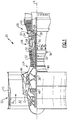
- FIG. 1 schematically illustrates a gas turbine engine 20.
- the gas turbine engine 20 is disclosed herein as a two-spool turbofan that generally incorporates a fan section 22, a compressor section 24, a combustor section 26 and a turbine section 28.
- the fan section 22 drives air along a bypass flow path B in a bypass duct defined within a nacelle 15, and also drives air along a core flow path C for compression and communication into the combustor section 26 then expansion through the turbine section 28.
- FIG. 1 schematically illustrates a gas turbine engine 20.
- the gas turbine engine 20 is disclosed herein as a two-spool turbofan that generally incorporates a fan section 22, a compressor section 24, a combustor section 26 and a turbine section 28.
- the fan section 22 drives air along a bypass flow path B in a bypass duct defined within a nacelle 15, and also drives air along a core flow path C for compression and communication into the combustor section 26 then expansion through the turbine section 28.
- FIG. 1 schematic
- the exemplary engine 20 generally includes a low speed spool 30 and a high speed spool 32 mounted for rotation about an engine central longitudinal axis A relative to an engine static structure 36 via several bearing systems 38.
- Terms such as “axial,” “radial,” “circumferential,” and variations of these terms are made with reference to the engine central axis A. It should be understood that various bearing systems 38 at various locations may alternatively or additionally be provided, and the location of bearing systems 38 may be varied as appropriate to the application.
- the low speed spool 30 generally includes an inner shaft 40 that interconnects, a first (or low) pressure compressor 44 and a first (or low) pressure turbine 46.
- the inner shaft 40 is connected to the fan 42 through a speed change mechanism, which in exemplary gas turbine engine 20 is illustrated as a geared architecture 48 to drive a fan 42 at a lower speed than the low speed spool 30.
- the high speed spool 32 includes an outer shaft 50 that interconnects a second (or high) pressure compressor 52 and a second (or high) pressure turbine 54.
- a combustor 56 is arranged in exemplary gas turbine 20 between the high pressure compressor 52 and the high pressure turbine 54.
- a mid-turbine frame 57 of the engine static structure 36 may be arranged generally between the high pressure turbine 54 and the low pressure turbine 46.
- the mid-turbine frame 57 further supports bearing systems 38 in the turbine section 28.
- the inner shaft 40 and the outer shaft 50 are concentric and rotate via bearing systems 38 about the engine central longitudinal axis A which is colline
- the core airflow is compressed by the low pressure compressor 44 then the high pressure compressor 52, mixed and burned with fuel in the combustor 56, then expanded over the high pressure turbine 54 and low pressure turbine 46.
- the mid-turbine frame 57 includes airfoils 59 which are in the core airflow path C.
- the turbines 46, 54 rotationally drive the respective low speed spool 30 and high speed spool 32 in response to the expansion.
- gear system 48 may be located aft of the low pressure compressor, or aft of the combustor section 26 or even aft of turbine section 28, and fan 42 may be positioned forward or aft of the location of gear system 48.
- the engine 20 in one example is a high-bypass geared aircraft engine.
- the engine 20 bypass ratio is greater than about 6:1, with an example embodiment being greater than about 10:1
- the geared architecture 48 is an epicyclic gear train, such as a planetary gear system or other gear system, with a gear reduction ratio of greater than about 2.3:1 and the low pressure turbine 46 has a pressure ratio that is greater than about five.
- the engine 20 bypass ratio is greater than about 10:1
- the fan diameter is significantly larger than that of the low pressure compressor 44
- the low pressure turbine 46 has a pressure ratio that is greater than about 5:1.
- the low pressure turbine 46 pressure ratio is pressure measured prior to the inlet of low pressure turbine 46 as related to the pressure at the outlet of the low pressure turbine 46 prior to an exhaust nozzle.
- the geared architecture 48 may be an epicycle gear train, such as a planetary gear system or other gear system, with a gear reduction ratio of greater than about 2.3:1 and less than about 5:1. It should be understood, however, that the above parameters are only exemplary of one embodiment of a geared architecture engine and that the present invention is applicable to other gas turbine engines including but not limited to direct drive turbofans.
- the fan section 22 of the engine 20 is designed for a particular flight condition -- typically cruise at about 0.8 Mach and about 35,000 feet (10,668 meters).
- the flight condition of 0.8 Mach and 35,000 ft (10,668 meters), with the engine at its best fuel consumption - also known as "bucket cruise Thrust Specific Fuel Consumption ('TSFC')" - is the industry standard parameter of lbm of fuel being burned divided by lbf of thrust the engine produces at that minimum point.
- "Low fan pressure ratio” is the pressure ratio across the fan blade alone, without a Fan Exit Guide Vane (“FEGV”) system.
- the low fan pressure ratio as disclosed herein according to one non-limiting embodiment is less than about 1.45:1.
- the "Low corrected fan tip speed” as disclosed herein according to one non-limiting embodiment is less than about 1150 ft / second (350.5 meters/second).
- FIG. 2 schematically shows an airfoil vane 100 from the turbine section 28 of the engine 20.
- the airfoil vane 100 is shown and described with reference to application in the turbine section 28, it is to be understood that the examples herein are also applicable to structural vanes in other sections of the engine 20.
- the example vane airfoil vane 100 is a "singlet” that has a single airfoil between the inner and outer platforms.
- the examples can also be applied to vane "doublets” that have two airfoils between inner and outer platforms, or vane “triplets” that have three airfoils between the inner and outer platforms.
- a plurality of airfoil vanes 100 are situated in a circumferential row about the engine central axis A.
- the airfoil vane 100 includes a second or inner platform 102, a first or outer platform 104, and an airfoil section 106 that spans between the inner and outer platforms 102/104.
- the airfoil section 106 includes an airfoil outer wall 108 that delimits the profile of the airfoil section 106.
- the outer wall 108 circumscribes an internal cavity 110.
- the airfoil vane 100 is formed of a ceramic material, such as a ceramic matrix composite (CMC) material.
- the CMC includes a ceramic matrix and ceramic fibers disposed in the ceramic matrix.
- the ceramic matrix may be, but is not limited to, silicon carbide (SiC) and the ceramic fibers may be, but are not limited to, silicon carbide (SiC) fibers.
- the CMC is comprised of fiber plies that are arranged in a stacked configuration and formed to the desired geometry of the airfoil vane 100.
- the fiber plies may be layers or tapes that are laid-up one on top of the other to form the stacked configuration.
- the fiber plies may be woven or unidirectional, for example.
- the airfoil vane 100 is a continuous body in that the fiber plies are uninterrupted through the platforms 102/104 and the airfoil section 106.
- the airfoil vane 100 may also be a monolithic ceramic material, such as a silicon-containing ceramic. Examples of such ceramics include silicon nitride and silicon carbide.
- FIG. 3 shows a portion of an example outer support ring 114.
- the outer support ring 114 is in turn connected to a casing structure of the engine 20.
- the outer support ring 114 is connected to the casing structure via lugs 116 that extend through openings 118.
- the outer platform 104 includes a leading edge 104a and a trailing edge 104b.
- Each of the leading and trailing edges 104a/104b include a recess 120a, 120b, respectively, in a radially outer face of the outer platform 104.
- the recesses 120a/120b can be machined into the outer platform 104 by any known method.
- the respective recesses 120a/120b of adjacent outer platforms 104 together define a slot 120.
- Figure 4 shows a cross-sectional view of the slot 120 taken along the section line A-A in Figure 2 .
- the outer support ring 114 includes pedestals 124 which extend radially inward from an inner surface of the outer support ring 114 and are configured to be received in the slot 120.
- the pedestal 124 has a geometry that generally tracks the geometry of the slot 120. That is, at least part of the radially inward face of the pedestal 124 has a geometry that corresponds to the geometry of the slot 120.
- Each recess 120a/120b is defined by a radial face and a circumferential face.
- a circumferential face 121a of the recess 120b in the trailing edge 104b of the outer platform 104 is generally perpendicular to a radial face 121b of the recess 120b.
- a circumferential face 122a of the recess 120a in the leading edge 104a of the outer platform 104 forms an obtuse angle with a radial face 122b of the recess 120a.
- the pedestal 124 includes a biased portion 126 in its radially inward face which corresponds to the radial face 122b of the recess 120a.
- other geometries of the recesses 120a/120b and the pedestal 124 are contemplated, so long as they track one another.
- a sealing element 128 is situated in the slot 120, between the platforms 104 and the outer support ring 114, to discourage leakage between adjacent airfoil vanes 100 and in particular between adjacent outer platforms 104 at a gap G.
- Each airfoil vane 100 receives cooling air in the internal cavity 110, such as bleed air from the compressor section 24. Leaking of this cooling air between adjacent airfoil vanes 100 decreases cooling efficiency of the individual airfoil vanes 100 and the local system, e.g., turbine 28, in this example.
- Figure 5 shows a detail view of the sealing element 128.
- the sealing element 128 has a geometry that generally tracks the geometry of the slot 120. That is, at least part of the periphery of the sealing element 128 has a geometry that corresponds to the geometry of the slot 120. Due to the corresponding geometry of the slot 120 and the sealing element 128, the sealing element 128 is trapped in the slot 120 by a form-fit relationship between the sealing element 128 and the slot 120 that retains the sealing element 128 in the slot 120 in axial and circumferential dimensions. As shown in Figure 2 , the sealing element 128 in this example is smaller in its axial extent than the axial extent of the slot 120. In other examples, the sealing element 128 has the same axial extent of the slot 120.
- the sealing element 128 has a main body portion 129 and a biased portion 130 extending from the main body portion 129.
- the biased portion 130 corresponds to the radial face 122a of the recess 120a, and is angled with respect to the main body portion 129 at an angle that corresponds to the angle between the circumferential and radial faces 122a/122b of the recess 120a. Accordingly, in this example, the biased portion 130 is situated in the recess 120a, while the main body portion 129 is situated in the recess 120b.
- the biased portion 130 is semi-circular in shape, e.g., the biased portion 130 has an arcuate edge, though other shapes are contemplated.
- the biased portion 126 of the pedestal 124 retains the biased portion 130 of the sealing element 128 against the circumferential face 122a of the recess 120a by urging the biased portion 130 of the sealing element 128 radially downward against the radial face 122a. Accordingly, the pedestal 124 provides radial retention of the sealing element 128 in the slot 120.
- the sealing element 128 experiences a pressure load P which is generally in a direction towards the central axis A of the engine 20 ( Figures 1 and 2 ).
- the pressure load P urges the sealing element 128, and especially the main body portion 129, which is situated normal to the pressure load P, radially inward towards the outer platform 104.
- the pedestals 124 include a cooling hole 131 which is configured to transmit cooling air, such as bleed air from the compressor section 24 ( Figure 1 ) through the outer support ring 114 into the slot 120 against the sealing element 128. In other examples some or all pedestals 124 do not include a cooling hole 131.
- the cooling air contributes to the pressure load P.
- a biasing member such as a spring, can be included to provide further biasing of the sealing element 128 against the outer platforms 104 in the radial direction.
- the main body portion 129 includes legs 132, which extend from the main body portion 129 to receive and thus engage the lugs 116 in the outer support ring 114.
- the legs 132 are situated at an opposite end of the main body portion 129 from the biased portion 130.
- the sealing element 128 is formed of a ductile material that is compatible with the CMC material of the platform 104.
- a compatible material is generally non-abrasive and non-reactive with respect to the CMC material of the platform 104. Accordingly, the sealing element 128 can deform at least somewhat during operation of the engine 20, for example, as a result of the pressure load P, to conform against the platform 104 and provide improved sealing.
- the sealing element 128 is formed form a high-temperature metal, such as a cobalt alloy.
- Some comparable sealing arrangements call for the machining of a circumferential slot into the leading/trailing edges 104a/104b radially inward from the outer face of the platforms 104, and placement of a seal in these circumferential slots.
- These seals can introduce circumferential tensions into the platforms 104, which in some examples, is in a direction that introduces interlaminar tensions between adjacent CMC plies (discussed above). Interlaminar tension can cause delamination, which can weaken the platforms 104.
- the foregoing sealing arrangement for adjacent airfoil vanes 100 allows the sealing element 128 to be situated and trapped in a slot 120 in the radially outer face of the outer platforms 104. Accordingly, the foregoing sealing arrangement avoids introducing interlaminar tension into the platforms 104.
- the slot 120 described herein is in a radially outer face of the radially outer platform 104, in other examples, the slot 120 can be included in a radially inner face of the radially inner platform 102.
- the support ring is an inner support ring. The same features and characteristics of the slot 120, support ring 114, and sealing element 128 apply.
Landscapes
- Engineering & Computer Science (AREA)
- Mechanical Engineering (AREA)
- General Engineering & Computer Science (AREA)
- Structures Of Non-Positive Displacement Pumps (AREA)
- Turbine Rotor Nozzle Sealing (AREA)
Abstract
Description
- A gas turbine engine typically includes a fan section, a compressor section, a combustor section and a turbine section. Air entering the compressor section is compressed and delivered into the combustion section where it is mixed with fuel and ignited to generate a high-energy exhaust gas flow. The high-energy exhaust gas flow expands through the turbine section to drive the compressor and the fan section. The compressor section typically includes low and high pressure compressors, and the turbine section includes low and high pressure turbines.
- Any of the fan section, the turbine section, and the compressor section include airfoils, such as for fan, compressor, or turbine blades/vanes. Cooling air is provided to the airfoils. Seals are provided to discourage leakage of this cooling air between adjacent airfoils.
- According to a first aspect of the present invention there is provided a gas turbine engine comprising a plurality of airfoil vanes situated in a circumferential row about an engine central axis. Each of the plurality of airfoil vanes include a first platform, and a second platform, and an airfoil section therebetween. A face of the first platform includes a trailing edge recess and a leading edge recess. The trailing edge recess and leading edge recesses of adjacent ones of the first platforms together define a slot. A sealing element situated in each slot. The sealing element has a geometry that tracks the geometry of the slot such that the seal is trapped in the slot by a form-fit relationship in circumferential and axial dimensions by a form-fit relationship between the sealing element and the slot.
- In an embodiment of the above embodiment, a support ring is configured to support each first platform. The support ring includes a plurality of pedestals which correspond to each slot and are configured to retain the sealing elements in the slots in a radial direction.
- In an embodiment of any of the above embodiments, the first platform is a radially outer platform and the support ring is connected to an engine casing structure.
- In an embodiment of any of the above embodiments, the sealing elements include one or more legs configured to engage the plurality of lugs.
- In an embodiment of any of the above embodiments, each slot includes first and second portions. The first portion is formed in a leading edge of each outer platform and the second portion is formed in a trailing edge of each outer platform.
- In an embodiment of any of the above embodiments, the first portion is defined by a radial face and a circumferential face. The circumferential face forms an obtuse angle with the axial face.
- In an embodiment of any of the above embodiments, the sealing element includes a main body portion and a biased portion which extends from the main body portion at an angle that corresponds to the obtuse angle.
- In an embodiment of any of the above embodiments, a support ring is configured to support each platform. The support ring includes a plurality of pedestals. Each pedestal includes a biased portion that corresponds to the circumferential face. The biased portion of the each pedestal is configured to bias the biased portion of each sealing element against the circumferential face.
- In an embodiment of any of the above embodiments, each pedestal includes a cooling hole which is configured to transmit cooling air through the support ring into each slot against each sealing element.
- In an embodiment of any of the above embodiments, the second portion is defined by an axial face and a circumferential face. The circumferential face is generally perpendicular to the axial face.
- In an embodiment of any of the above embodiments, each sealing element is formed of a ductile metallic material.
- According to a second aspect of the present invention there is provided a method of sealing a plurality of airfoil vanes comprising situating a sealing element in a slot formed in a face of platforms of adjacent airfoil vanes. The sealing element has a geometry that tracks the geometry of the slot such that the sealing element is trapped in the slot in circumferential and axial dimension by a form-fit relationship between the sealing element and the slot.
- In an embodiment of the above embodiments, the platforms are supported in a support ring. The support ring includes a pedestal that is configured to be received in the slot and retain the sealing element in the slot in a radial dimension.
- In an embodiment of any of the above embodiments, cooling air is provided to the slot and against the sealing element via a cooling hole in the pedestal.
- In an embodiment of any of the above embodiments, the slot includes first and second portions. The first portion formed in a leading edge of an platform of the adjacent outer platforms and the second portion formed in a trailing edge of the other platform of the adjacent outer platforms.
- In an embodiment of any of the above embodiments, the first portion is defined by a radial face and a circumferential face. The circumferential face forms an obtuse angle with the axial face.
- In an embodiment of any of the above embodiments, the sealing element includes a main body portion and a biased portion which extends from the main body portion at an angle that corresponds to the obtuse angle.
- In an embodiment of any of the above embodiments, the platforms are supported in the support ring. The support ring includes a pedestal that is configured to retain the sealing element in the slot.
- In an embodiment of any of the above embodiments, the pedestal includes a biased portion that corresponds to the circumferential face. The biased portion is configured to trap the biased portion of the sealing element against the circumferential face.
- In an embodiment of any of the above emboidments, each sealing element is formed of a ductile metallic material.
- Although the different examples have the specific components shown in the illustrations, embodiments of this invention are not limited to those particular combinations. It is possible to use some of the components or features from one of the examples in combination with features or components from another one of the examples.
- These and other features disclosed herein can be best understood from the following specification and drawings, the following of which is a brief description.
-
-
Figure 1 schematically shows an example gas turbine engine according to the present invention. -
Figure 2 schematically shows an embodiment of an airfoil vane for the gas turbine engine ofFigure 1 . -
Figure 3 schematically shows a portion of an embodiment of a support ring for the airfoil vane ofFigure 2 . -
Figure 4 schematically shows a detail view of a slot in an outer platform of the airfoil vane ofFigure 2 . -
Figure 5 schematically shows an embodiment of a sealing element for the slot ofFigures 2-4 . -
Figure 1 schematically illustrates agas turbine engine 20. Thegas turbine engine 20 is disclosed herein as a two-spool turbofan that generally incorporates afan section 22, acompressor section 24, acombustor section 26 and aturbine section 28. Thefan section 22 drives air along a bypass flow path B in a bypass duct defined within anacelle 15, and also drives air along a core flow path C for compression and communication into thecombustor section 26 then expansion through theturbine section 28. Although depicted as a two-spool turbofan gas turbine engine in the disclosed non-limiting embodiment, it should be understood that the concepts described herein are not limited to use with two-spool turbofans as the teachings may be applied to other types of turbine engines including but not limited to three-spool architectures. - The
exemplary engine 20 generally includes alow speed spool 30 and ahigh speed spool 32 mounted for rotation about an engine central longitudinal axis A relative to an enginestatic structure 36 viaseveral bearing systems 38. Terms such as "axial," "radial," "circumferential," and variations of these terms are made with reference to the engine central axis A. It should be understood thatvarious bearing systems 38 at various locations may alternatively or additionally be provided, and the location ofbearing systems 38 may be varied as appropriate to the application. - The
low speed spool 30 generally includes aninner shaft 40 that interconnects, a first (or low) pressure compressor 44 and a first (or low)pressure turbine 46. Theinner shaft 40 is connected to thefan 42 through a speed change mechanism, which in exemplarygas turbine engine 20 is illustrated as a gearedarchitecture 48 to drive afan 42 at a lower speed than thelow speed spool 30. Thehigh speed spool 32 includes anouter shaft 50 that interconnects a second (or high)pressure compressor 52 and a second (or high)pressure turbine 54. Acombustor 56 is arranged inexemplary gas turbine 20 between thehigh pressure compressor 52 and thehigh pressure turbine 54. Amid-turbine frame 57 of the enginestatic structure 36 may be arranged generally between thehigh pressure turbine 54 and thelow pressure turbine 46. Themid-turbine frame 57 furthersupports bearing systems 38 in theturbine section 28. Theinner shaft 40 and theouter shaft 50 are concentric and rotate via bearingsystems 38 about the engine central longitudinal axis A which is collinear with their longitudinal axes. - The core airflow is compressed by the low pressure compressor 44 then the
high pressure compressor 52, mixed and burned with fuel in thecombustor 56, then expanded over thehigh pressure turbine 54 andlow pressure turbine 46. Themid-turbine frame 57 includesairfoils 59 which are in the core airflow path C. Theturbines low speed spool 30 andhigh speed spool 32 in response to the expansion. It will be appreciated that each of the positions of thefan section 22,compressor section 24,combustor section 26,turbine section 28, and fandrive gear system 48 may be varied. For example,gear system 48 may be located aft of the low pressure compressor, or aft of thecombustor section 26 or even aft ofturbine section 28, andfan 42 may be positioned forward or aft of the location ofgear system 48. - The
engine 20 in one example is a high-bypass geared aircraft engine. In a further example, theengine 20 bypass ratio is greater than about 6:1, with an example embodiment being greater than about 10:1, the gearedarchitecture 48 is an epicyclic gear train, such as a planetary gear system or other gear system, with a gear reduction ratio of greater than about 2.3:1 and thelow pressure turbine 46 has a pressure ratio that is greater than about five. In one disclosed embodiment, theengine 20 bypass ratio is greater than about 10:1, the fan diameter is significantly larger than that of the low pressure compressor 44, and thelow pressure turbine 46 has a pressure ratio that is greater than about 5:1. Thelow pressure turbine 46 pressure ratio is pressure measured prior to the inlet oflow pressure turbine 46 as related to the pressure at the outlet of thelow pressure turbine 46 prior to an exhaust nozzle. The gearedarchitecture 48 may be an epicycle gear train, such as a planetary gear system or other gear system, with a gear reduction ratio of greater than about 2.3:1 and less than about 5:1. It should be understood, however, that the above parameters are only exemplary of one embodiment of a geared architecture engine and that the present invention is applicable to other gas turbine engines including but not limited to direct drive turbofans. - A significant amount of thrust is provided by the bypass flow B due to the high bypass ratio. The
fan section 22 of theengine 20 is designed for a particular flight condition -- typically cruise at about 0.8 Mach and about 35,000 feet (10,668 meters). The flight condition of 0.8 Mach and 35,000 ft (10,668 meters), with the engine at its best fuel consumption - also known as "bucket cruise Thrust Specific Fuel Consumption ('TSFC')" - is the industry standard parameter of lbm of fuel being burned divided by lbf of thrust the engine produces at that minimum point. "Low fan pressure ratio" is the pressure ratio across the fan blade alone, without a Fan Exit Guide Vane ("FEGV") system. The low fan pressure ratio as disclosed herein according to one non-limiting embodiment is less than about 1.45:1. "Low corrected fan tip speed" is the actual fan tip speed in ft/sec divided by an industry standard temperature correction of [(Tram °R) / (518.7 °R)]0.5 (where °R = K x 9/5). The "Low corrected fan tip speed" as disclosed herein according to one non-limiting embodiment is less than about 1150 ft / second (350.5 meters/second). -
Figure 2 schematically shows anairfoil vane 100 from theturbine section 28 of theengine 20. Although theairfoil vane 100 is shown and described with reference to application in theturbine section 28, it is to be understood that the examples herein are also applicable to structural vanes in other sections of theengine 20. Additionally, the examplevane airfoil vane 100 is a "singlet" that has a single airfoil between the inner and outer platforms. However, it is to be understood that the examples can also be applied to vane "doublets" that have two airfoils between inner and outer platforms, or vane "triplets" that have three airfoils between the inner and outer platforms. Thus, "a" and "an" used with regard to airfoils or airfoil sections of thevane airfoil vane 100 do not preclude more than one. A plurality ofairfoil vanes 100 are situated in a circumferential row about the engine central axis A. Theairfoil vane 100 includes a second orinner platform 102, a first orouter platform 104, and anairfoil section 106 that spans between the inner andouter platforms 102/104. Theairfoil section 106 includes an airfoilouter wall 108 that delimits the profile of theairfoil section 106. Theouter wall 108 circumscribes aninternal cavity 110. - In one example, the
airfoil vane 100 is formed of a ceramic material, such as a ceramic matrix composite (CMC) material. For example, the CMC includes a ceramic matrix and ceramic fibers disposed in the ceramic matrix. The ceramic matrix may be, but is not limited to, silicon carbide (SiC) and the ceramic fibers may be, but are not limited to, silicon carbide (SiC) fibers. The CMC is comprised of fiber plies that are arranged in a stacked configuration and formed to the desired geometry of theairfoil vane 100. For instance, the fiber plies may be layers or tapes that are laid-up one on top of the other to form the stacked configuration. The fiber plies may be woven or unidirectional, for example. At least a portion of the fiber plies are continuous through theplatforms 102/104 and theairfoil section 106. In this regard, theairfoil vane 100 is a continuous body in that the fiber plies are uninterrupted through theplatforms 102/104 and theairfoil section 106. Theairfoil vane 100 may also be a monolithic ceramic material, such as a silicon-containing ceramic. Examples of such ceramics include silicon nitride and silicon carbide. - The inner and
outer platforms 102/104 are supported in inner and outer support rings, respectively.Figure 3 shows a portion of an exampleouter support ring 114. Theouter support ring 114 is in turn connected to a casing structure of theengine 20. In the example ofFigure 3 , theouter support ring 114 is connected to the casing structure vialugs 116 that extend throughopenings 118. - Referring back to
Figure 2 , theouter platform 104 includes aleading edge 104a and a trailingedge 104b. Each of the leading and trailingedges 104a/104b include arecess outer platform 104. Therecesses 120a/120b can be machined into theouter platform 104 by any known method. Therespective recesses 120a/120b of adjacentouter platforms 104 together define aslot 120. -
Figure 4 shows a cross-sectional view of theslot 120 taken along the section line A-A inFigure 2 . Referring toFigures 3 and 4 , theouter support ring 114 includespedestals 124 which extend radially inward from an inner surface of theouter support ring 114 and are configured to be received in theslot 120. Thepedestal 124 has a geometry that generally tracks the geometry of theslot 120. That is, at least part of the radially inward face of thepedestal 124 has a geometry that corresponds to the geometry of theslot 120. - Each
recess 120a/120b is defined by a radial face and a circumferential face. In this example, acircumferential face 121a of therecess 120b in the trailingedge 104b of theouter platform 104 is generally perpendicular to aradial face 121b of therecess 120b. Acircumferential face 122a of therecess 120a in theleading edge 104a of theouter platform 104 forms an obtuse angle with aradial face 122b of therecess 120a. Accordingly, in this example, thepedestal 124 includes abiased portion 126 in its radially inward face which corresponds to theradial face 122b of therecess 120a. However, other geometries of therecesses 120a/120b and thepedestal 124 are contemplated, so long as they track one another. - A sealing
element 128 is situated in theslot 120, between theplatforms 104 and theouter support ring 114, to discourage leakage between adjacentairfoil vanes 100 and in particular between adjacentouter platforms 104 at a gap G. Eachairfoil vane 100 receives cooling air in theinternal cavity 110, such as bleed air from thecompressor section 24. Leaking of this cooling air between adjacentairfoil vanes 100 decreases cooling efficiency of theindividual airfoil vanes 100 and the local system, e.g.,turbine 28, in this example. -
Figure 5 shows a detail view of the sealingelement 128. Referring toFigures 2-5 , the sealingelement 128 has a geometry that generally tracks the geometry of theslot 120. That is, at least part of the periphery of the sealingelement 128 has a geometry that corresponds to the geometry of theslot 120. Due to the corresponding geometry of theslot 120 and the sealingelement 128, the sealingelement 128 is trapped in theslot 120 by a form-fit relationship between the sealingelement 128 and theslot 120 that retains the sealingelement 128 in theslot 120 in axial and circumferential dimensions. As shown inFigure 2 , the sealingelement 128 in this example is smaller in its axial extent than the axial extent of theslot 120. In other examples, the sealingelement 128 has the same axial extent of theslot 120. - In this example, the sealing
element 128 has amain body portion 129 and abiased portion 130 extending from themain body portion 129. Thebiased portion 130 corresponds to theradial face 122a of therecess 120a, and is angled with respect to themain body portion 129 at an angle that corresponds to the angle between the circumferential andradial faces 122a/122b of therecess 120a. Accordingly, in this example, thebiased portion 130 is situated in therecess 120a, while themain body portion 129 is situated in therecess 120b. In this example, thebiased portion 130 is semi-circular in shape, e.g., thebiased portion 130 has an arcuate edge, though other shapes are contemplated. - As best shown in
Figure 4 , thebiased portion 126 of thepedestal 124 retains thebiased portion 130 of the sealingelement 128 against thecircumferential face 122a of therecess 120a by urging thebiased portion 130 of the sealingelement 128 radially downward against theradial face 122a. Accordingly, thepedestal 124 provides radial retention of the sealingelement 128 in theslot 120. During operation of theengine 20, the sealingelement 128 experiences a pressure load P which is generally in a direction towards the central axis A of the engine 20 (Figures 1 and2 ). The pressure load P urges the sealingelement 128, and especially themain body portion 129, which is situated normal to the pressure load P, radially inward towards theouter platform 104. The pressure load P and thepedestal 124 thus together trap the sealing element 128 (e.g, both themain body portion 129 and the biased portion 130) in the radial direction against the adjacentouter platforms 104 to provide the sealing discussed above. In one example, thepedestals 124 include acooling hole 131 which is configured to transmit cooling air, such as bleed air from the compressor section 24 (Figure 1 ) through theouter support ring 114 into theslot 120 against the sealingelement 128. In other examples some or allpedestals 124 do not include acooling hole 131. The cooling air contributes to the pressure load P. In another example, a biasing member, such as a spring, can be included to provide further biasing of the sealingelement 128 against theouter platforms 104 in the radial direction. - The
main body portion 129 includeslegs 132, which extend from themain body portion 129 to receive and thus engage thelugs 116 in theouter support ring 114. Thelegs 132 are situated at an opposite end of themain body portion 129 from thebiased portion 130. - The sealing
element 128 is formed of a ductile material that is compatible with the CMC material of theplatform 104. A compatible material is generally non-abrasive and non-reactive with respect to the CMC material of theplatform 104. Accordingly, the sealingelement 128 can deform at least somewhat during operation of theengine 20, for example, as a result of the pressure load P, to conform against theplatform 104 and provide improved sealing. In some examples, the sealingelement 128 is formed form a high-temperature metal, such as a cobalt alloy. - Some comparable sealing arrangements call for the machining of a circumferential slot into the leading/trailing
edges 104a/104b radially inward from the outer face of theplatforms 104, and placement of a seal in these circumferential slots. These seals can introduce circumferential tensions into theplatforms 104, which in some examples, is in a direction that introduces interlaminar tensions between adjacent CMC plies (discussed above). Interlaminar tension can cause delamination, which can weaken theplatforms 104. The foregoing sealing arrangement foradjacent airfoil vanes 100 allows the sealingelement 128 to be situated and trapped in aslot 120 in the radially outer face of theouter platforms 104. Accordingly, the foregoing sealing arrangement avoids introducing interlaminar tension into theplatforms 104. - Though the
slot 120 described herein is in a radially outer face of the radiallyouter platform 104, in other examples, theslot 120 can be included in a radially inner face of the radiallyinner platform 102. In these examples, the support ring is an inner support ring. The same features and characteristics of theslot 120,support ring 114, and sealingelement 128 apply. - Although the different examples are illustrated as having specific components, the examples of this disclosure are not limited to those particular combinations. It is possible to use some of the components or features from any of the embodiments in combination with features or components from any of the other embodiments.
- The foregoing description shall be interpreted as illustrative and not in any limiting sense. A worker of ordinary skill in the art would understand that certain modifications could come within the scope of this disclosure. For these reasons, the following claims should be studied to determine the true scope and content of this disclosure.
Claims (14)
- An gas turbine engine (20), comprising:a plurality of airfoil vanes (100) situated in a circumferential row about an engine central axis (A), each of the plurality of airfoil vanes (100) including a first platform (104), and a second platform (102), and an airfoil section (106) therebetween, wherein a face of the first platform (104) includes a trailing edge recess (120b) and a leading edge recess (120a), and the trailing edge (120b) recess and leading edge (120a) recesses of adjacent ones of the first platforms (104) together define a slot (120); anda sealing element (128) situated in each slot (120), the sealing element (128) having a geometry that tracks the geometry of the slot (120) such that the seal is trapped in the slot (120) by a form-fit relationship in circumferential and axial dimensions by a form-fit relationship between the sealing element (128) and the slot (120).
- The gas turbine engine (20) of claim 1, further comprising a support ring (114) configured to support each first platform (104), the support ring (114) including a plurality of pedestals (124) corresponding to each slot (120) and configured to retain the sealing elements (128) in the slots (120) in a radial direction.
- The gas turbine engine (20) of claim 2, wherein the first platform (104) is a radially outer platform and the support ring (114) is connected to an engine (20) casing structure by a plurality of lugs (116).
- The gas turbine engine (20) of any of claims 1 to 3, wherein the sealing elements (128) include one or more legs (132) configured to engage the plurality of lugs (116).
- A method of sealing a plurality of airfoil vanes (100), comprising:
situating a sealing element (128) in a slot (120) formed in a face of platforms (102, 104) of adjacent airfoil vanes (100), wherein the sealing element (128) has a geometry that tracks the geometry of the slot (120) such that the sealing element (128) is trapped in the slot (120) in circumferential and axial dimension by a form-fit relationship between the sealing element (128) and the slot (120). - The method of claim 5, further comprising supporting the platforms (102, 104) in a support ring (114), the support ring (114) including a pedestal (124) that is configured to be received in the slot (120) and retain the sealing element (128) in the slot (120) in a radial dimension.
- The gas turbine engine (20) of any of claims 1 to 4 or the method of claims 5 or 6, wherein each slot (120) includes first and second portions (120a, 120b), the first portion formed in a leading edge (104a) of each platform (104) and the second portion formed in a trailing edge (104b) of each platform (104).
- The gas turbine engine (20) of any of claims 1 to 4 or 7 or the method of any of claims 5 to 7, wherein the first portion (120a) is defined by a radial face (122b) and a circumferential face (122a), and the circumferential face (122a) forms an obtuse angle with the radial face (122b).
- The gas turbine engine (20) or method of claim 8, wherein the sealing element (128) includes a main body portion (129) and a biased portion (130) extending from the main body portion (129) at an angle that corresponds to the obtuse angle.
- The method of claim 9, further comprising supporting the platforms (104) in a support ring (114), the support ring (114) including a pedestal (124) that is configured to retain the sealing element (128) in the slot (120).
- The method of claim 10, wherein the pedestal (124) includes a biased portion (126) that corresponds to the circumferential face (121b), the biased portion (126) configured to trap the biased portion (130) of the sealing element (128) against the circumferential face (121b).
- The gas turbine engine (20) or method of claim 11, wherein each pedestal (124) includes a cooling hole (131) configured to transmit cooling air through the support ring (114) into each slot (120) against each sealing element (128).
- The gas turbine engine (20) or method of any of claims 7 to 12, wherein the second portion (120b) is defined by a radial face (121b) and a circumferential face (121a), and the circumferential face (121a) is generally perpendicular to the radial face (121b).
- The gas turbine engine (20) of any of claims 1 to 4 or 7 to 13 or the method of any of claims 5 to 13, wherein each sealing element (128) is formed of a ductile metallic material.
Applications Claiming Priority (1)
| Application Number | Priority Date | Filing Date | Title |
|---|---|---|---|
| US16/677,262 US11187096B2 (en) | 2019-11-07 | 2019-11-07 | Platform seal |
Publications (1)
| Publication Number | Publication Date |
|---|---|
| EP3819474A1 true EP3819474A1 (en) | 2021-05-12 |
Family
ID=73059746
Family Applications (1)
| Application Number | Title | Priority Date | Filing Date |
|---|---|---|---|
| EP20205712.1A Pending EP3819474A1 (en) | 2019-11-07 | 2020-11-04 | Platform seal for a gas turbine engine |
Country Status (2)
| Country | Link |
|---|---|
| US (1) | US11187096B2 (en) |
| EP (1) | EP3819474A1 (en) |
Families Citing this family (2)
| Publication number | Priority date | Publication date | Assignee | Title |
|---|---|---|---|---|
| US11365642B2 (en) * | 2020-04-09 | 2022-06-21 | Raytheon Technologies Corporation | Vane support system with seal |
| US11512596B2 (en) * | 2021-03-25 | 2022-11-29 | Raytheon Technologies Corporation | Vane arc segment with flange having step |
Citations (7)
| Publication number | Priority date | Publication date | Assignee | Title |
|---|---|---|---|---|
| US3966356A (en) * | 1975-09-22 | 1976-06-29 | General Motors Corporation | Blade tip seal mount |
| US20020187040A1 (en) * | 2001-06-06 | 2002-12-12 | Predmore Daniel Ross | Overlapping interference seal and methods for forming the seal |
| US20150377035A1 (en) * | 2014-06-27 | 2015-12-31 | Rolls-Royce Corporation | Segmented turbine shroud with seals |
| US20160290145A1 (en) * | 2015-04-01 | 2016-10-06 | Herakles | Turbine ring assembly with sealing |
| EP3088679A1 (en) * | 2015-04-30 | 2016-11-02 | Rolls-Royce Corporation | Seal for a gas turbine engine assembly |
| EP3141703A1 (en) * | 2015-09-09 | 2017-03-15 | United Technologies Corporation | Seal assembly for turbine engine component |
| US20190153886A1 (en) * | 2017-11-21 | 2019-05-23 | Rolls-Royce Corporation | Turbine shroud assembly with seals |
Family Cites Families (11)
| Publication number | Priority date | Publication date | Assignee | Title |
|---|---|---|---|---|
| US5154577A (en) * | 1991-01-17 | 1992-10-13 | General Electric Company | Flexible three-piece seal assembly |
| US5868398A (en) * | 1997-05-20 | 1999-02-09 | United Technologies Corporation | Gas turbine stator vane seal |
| US6179560B1 (en) * | 1998-12-16 | 2001-01-30 | United Technologies Corporation | Turbomachinery module with improved maintainability |
| US6893214B2 (en) | 2002-12-20 | 2005-05-17 | General Electric Company | Shroud segment and assembly with surface recessed seal bridging adjacent members |
| WO2004074640A1 (en) * | 2003-02-19 | 2004-09-02 | Alstom Technology Ltd | Sealing arrangement, particularly for the blade segments of gas turbines |
| US8182208B2 (en) * | 2007-07-10 | 2012-05-22 | United Technologies Corp. | Gas turbine systems involving feather seals |
| US8308428B2 (en) * | 2007-10-09 | 2012-11-13 | United Technologies Corporation | Seal assembly retention feature and assembly method |
| US8684673B2 (en) * | 2010-06-02 | 2014-04-01 | Siemens Energy, Inc. | Static seal for turbine engine |
| US9714580B2 (en) | 2013-07-24 | 2017-07-25 | United Technologies Corporation | Trough seal for gas turbine engine |
| EP3039269B1 (en) * | 2013-08-29 | 2020-05-06 | United Technologies Corporation | Gas turbine engine and assembly method |
| JP6763157B2 (en) | 2016-03-11 | 2020-09-30 | 株式会社Ihi | Turbine nozzle |
-
2019
- 2019-11-07 US US16/677,262 patent/US11187096B2/en active Active
-
2020
- 2020-11-04 EP EP20205712.1A patent/EP3819474A1/en active Pending
Patent Citations (7)
| Publication number | Priority date | Publication date | Assignee | Title |
|---|---|---|---|---|
| US3966356A (en) * | 1975-09-22 | 1976-06-29 | General Motors Corporation | Blade tip seal mount |
| US20020187040A1 (en) * | 2001-06-06 | 2002-12-12 | Predmore Daniel Ross | Overlapping interference seal and methods for forming the seal |
| US20150377035A1 (en) * | 2014-06-27 | 2015-12-31 | Rolls-Royce Corporation | Segmented turbine shroud with seals |
| US20160290145A1 (en) * | 2015-04-01 | 2016-10-06 | Herakles | Turbine ring assembly with sealing |
| EP3088679A1 (en) * | 2015-04-30 | 2016-11-02 | Rolls-Royce Corporation | Seal for a gas turbine engine assembly |
| EP3141703A1 (en) * | 2015-09-09 | 2017-03-15 | United Technologies Corporation | Seal assembly for turbine engine component |
| US20190153886A1 (en) * | 2017-11-21 | 2019-05-23 | Rolls-Royce Corporation | Turbine shroud assembly with seals |
Also Published As
| Publication number | Publication date |
|---|---|
| US11187096B2 (en) | 2021-11-30 |
| US20210140335A1 (en) | 2021-05-13 |
Similar Documents
| Publication | Publication Date | Title |
|---|---|---|
| US10968761B2 (en) | Seal assembly with impingement seal plate | |
| US20220364483A1 (en) | Gas turbine engine component | |
| US11021986B2 (en) | Seal assembly for gas turbine engine | |
| EP4086436A1 (en) | Gas turbine vane assembly | |
| EP3219934B1 (en) | Seal assembly for gas turbine engine | |
| EP3812551B1 (en) | Vane with l-shaped seal | |
| US20160003077A1 (en) | Gas turbine engine turbine vane rail seal | |
| US12454893B2 (en) | Airfoil anti-rotation ring and assembly | |
| US11454130B2 (en) | Blade outer air seal with inward-facing dovetail hooks and backside cooling | |
| US10280756B2 (en) | Gas turbine engine airfoil | |
| EP3819474A1 (en) | Platform seal for a gas turbine engine | |
| US11913340B2 (en) | Air seal system with backside abradable layer | |
| EP3825518B1 (en) | Vane retention assembly | |
| EP4253726B1 (en) | Cmc vane mate face flanges with through-ply seal slots | |
| US12215606B2 (en) | Turbine engine with TOBI supporting vanes | |
| US20190316480A1 (en) | Seal assembly for gas turbine engine | |
| EP3808938B1 (en) | Airfoil component with trailing end margin and cutback | |
| EP2890878B1 (en) | Blade outer air seal | |
| EP3819471B1 (en) | Stator vane assembly with seal | |
| EP4056812A1 (en) | Chevron grooved mateface seal |
Legal Events
| Date | Code | Title | Description |
|---|---|---|---|
| PUAI | Public reference made under article 153(3) epc to a published international application that has entered the european phase |
Free format text: ORIGINAL CODE: 0009012 |
|
| STAA | Information on the status of an ep patent application or granted ep patent |
Free format text: STATUS: THE APPLICATION HAS BEEN PUBLISHED |
|
| AK | Designated contracting states |
Kind code of ref document: A1 Designated state(s): AL AT BE BG CH CY CZ DE DK EE ES FI FR GB GR HR HU IE IS IT LI LT LU LV MC MK MT NL NO PL PT RO RS SE SI SK SM TR |
|
| STAA | Information on the status of an ep patent application or granted ep patent |
Free format text: STATUS: REQUEST FOR EXAMINATION WAS MADE |
|
| 17P | Request for examination filed |
Effective date: 20211112 |
|
| RBV | Designated contracting states (corrected) |
Designated state(s): AL AT BE BG CH CY CZ DE DK EE ES FI FR GB GR HR HU IE IS IT LI LT LU LV MC MK MT NL NO PL PT RO RS SE SI SK SM TR |
|
| STAA | Information on the status of an ep patent application or granted ep patent |
Free format text: STATUS: EXAMINATION IS IN PROGRESS |
|
| 17Q | First examination report despatched |
Effective date: 20230612 |
|
| RAP3 | Party data changed (applicant data changed or rights of an application transferred) |
Owner name: RTX CORPORATION |