EP3819458A1 - Strengthened percussive drill string female coupling - Google Patents
Strengthened percussive drill string female coupling Download PDFInfo
- Publication number
- EP3819458A1 EP3819458A1 EP19208106.5A EP19208106A EP3819458A1 EP 3819458 A1 EP3819458 A1 EP 3819458A1 EP 19208106 A EP19208106 A EP 19208106A EP 3819458 A1 EP3819458 A1 EP 3819458A1
- Authority
- EP
- European Patent Office
- Prior art keywords
- female
- region
- length
- drill string
- thread
- Prior art date
- Legal status (The legal status is an assumption and is not a legal conclusion. Google has not performed a legal analysis and makes no representation as to the accuracy of the status listed.)
- Granted
Links
Images




Classifications
-
- E—FIXED CONSTRUCTIONS
- E21—EARTH OR ROCK DRILLING; MINING
- E21B—EARTH OR ROCK DRILLING; OBTAINING OIL, GAS, WATER, SOLUBLE OR MELTABLE MATERIALS OR A SLURRY OF MINERALS FROM WELLS
- E21B17/00—Drilling rods or pipes; Flexible drill strings; Kellies; Drill collars; Sucker rods; Cables; Casings; Tubings
- E21B17/02—Couplings; joints
- E21B17/04—Couplings; joints between rod or the like and bit or between rod and rod or the like
- E21B17/042—Threaded
- E21B17/0426—Threaded with a threaded cylindrical portion, e.g. for percussion rods
Definitions
- the present invention relates to a drill string coupling for connecting individual elongate drill string members and in particular, although not exclusively, to a strengthened female coupling.
- Percussion drilling is used to create a long borehole via a plurality of elongate drill string rods coupled together end-to-end by interconnected male and female threads.
- the well-established technique breaks rock by hammering impacts transferred from the rock drill bit, mounted at one end of the drill string, to the rock at the bottom of the borehole.
- the energy required to break the rock is generated by a hydraulically driven piston that contacts the end of the drill string (via a shank adaptor) to create a stress (or shock) wave that propagates through the drill string and ultimately to the base rock level.
- Conventional male and female threaded couplings are described in US 4,332,502 ; US 4,398,756 ; US 4,687,368 and DE 2800887 .
- the joint When the male and female threaded ends of neighbouring drill rods are coupled to create the drill string, the joint is typically subjected to bending forces during drilling from the stress waves that propagate the drill string. These bending moments fatigue the coupling and lead to breakage within the threaded portion of the joint.
- the drill coupling will fail by the coupling either eventually becoming worn out, which is predictable, or fail prematurely due to high stress waves which is unpredictable and causes increased down time for the user.
- a drill string for percussive drilling comprising; a first elongate percussive drill rod having and a main section and an externally threaded male end; a second elongate percussive drill rod having a main section and a female end comprising an internally threaded mounting sleeve; wherein the male and female ends have respective threads for percussive drilling to enable the male end to be secured inside the female end such that an axial length from an axially rearward end on the female end to an end most female thread on the female end overlaps axially with the male end to form a coupling region; wherein a thread clearance area is formed adjacent to the end most female thread in the region between the end most female thread and an axial inner wall of the female end; characterized in that: the mounting sleeve has a first region having a first outer skirt diameter, D 1 , at the axially rearward end and a second outer skirt diameter, D 2 , along part of the axial length
- the length, L 2 , of the strengthened region extends at least along the length of the inner most female thread.
- the thread exit is a weak part of the joint and is where the high stresses build up. Therefore, it is advantageous to reinforce the coupling in this region.
- length, L 2 of the strengthened region extends at least along the length of the thread clearance area.
- the thread exit is a weak part of the joint and is where the high stresses build up. Therefore, it is advantageous to reinforce the coupling in this region.
- the length, L 2 of the strengthened region extends at least along the length of two thread turns from the inner most female thread.
- this will add further support to reinforce the coupling.
- the first region of the mounting sleeve having the first outer skirt diameter, D 1 extends across at least the length of the least a first female thread.
- the strengthened region ends before the position of the first female thread, preferably before the second female thread so that the flushing of the drill hole is not limited too much.
- the length, L 2 of the strengthened region is between 0.2 and 0.8 times the length of the axial length, L 1 of the coupling region. If the length of the strengthened region is less than 0.2 times the length of the coupling region the benefit of the strengthening will not be gained. If the length of the strengthened region is greater than 0.8 times the length of the coupling region the efficiency in clearing the drilled hole of rock cuttings would be reduced.
- the length of the strengthen region is selected to suit different sizes of drills rods and different types of coupling.
- the strengthened region extends to a transition section that extends between the mounting sleeve and the main length section.
- the end position of the strengthened region should be optimised depending on the drilling assembly, it may be advantageous that the strengthened region extends as far as the transition section for some designs to provide reinforcement to this region.
- the female end has a thread pitch length, L 3 , preferably the length, L 2 of the strengthened region is at least the length of one thread pitch length, L 3 .
- the strengthened section will be sufficiently long to provide a substantial reinforcement.
- the outer skirt diameter, D 2 of the strengthened region is between 1-10% greater than the outer skirt diameter, D 1 at the axially rearward end of the female end.
- the thickness of the strengthened region will depend on the size of the hole being drilled. If the outer skirt diameter of the strengthened region is at least 1% greater than the outer skirt diameter of the female end at the end most surface so that the coupling region is sufficiently increased, but no more than 10% greater so that the efficiency of the flushing in the drill hole is not compromised too much.
- the outer skirt diameter, D 2 , of the strengthened region is between 0.1 to 10 mm greater than the outer skirt diameter, D 1 , at the axially rearward end of the female end.
- the presence of larger cross section in the strengthened region provides reinforcement at the critical location to reduce the level of stress in the most fragile part of the coupling region.
- the increased outer skirt diameter of the strengthened region will increase the fatigue resistance of the drill string rod components. If D 2 is less than 0.1 mm greater than D 1 , then the benefit of the level of stress in the coupling region will not be significantly reduced. Generally, increasing the difference between D 2 and D 1 will increase the fatigue resistance. If D 2 is more than 10 mm greater than D 1 there will be a detrimental effect of the efficiency of the debris removal in the drilled hole.
- the steel body of the drill string rods wears down due to the sliding contact with the rock and from the cuttings being flushed out of the hole.
- the reinforcement in the strengthened region will eventually get worn down to the normal outer skirt diameter and so then the passageway for the cutting will revert to normal.
- the addition of the strengthened region will advantageously increase the lifetime of the drill string rods and reduce the likelihood of premature failure.
- the most preferred outer skirt diameter, D 1 will depend on the size of the hole being used, the size of the drill rods and the type of coupling.
- the mounting sleeve has a first wall thickness, T 1 , at the axial rearward end and a second wall thickness, T 2 , in the strengthened region, wherein T 2 > T 1 .
- T 1 first wall thickness
- T 2 second wall thickness
- the inner dimensions inside the cavity of the female end are kept unchanged.
- the increase in outer skirt diameter in the strengthened region is created by increasing the wall thickness of the female end in this region. This is advantageous as then there is no reduction to the strength of the male end of the coupling, which could also lead to premature failure.
- the strengthened region is centred around an intersection between the end most female thread and the thread clearance area.
- this targets the strengthening to the weakest point of the coupling.
- the male end and the female end are helically threaded and comprise between two and seven complete helical turns.
- this range of the complete helical turns provides the best balance between coupling strength and cost.
- the main section of the drill string has an outside skirt diameter, D 3 , wherein the outer skirt diameter, D 1 , of the axially rearward end of the female end is greater than the outside skirt diameter, D 3 , of the main section.
- This type of arrangement would be used for a guiding tube.
- the main section of the drill rod has an outside skirt diameter, D 3 , wherein the outer skirt diameter, D 1 , of the axially rearward end most surface of the female end is the same as the outside skirt diameter, D 3 , of the main section.
- This type of arrangement would be used for a drill tube.
- FIG. 1 Another aspect of the present invention is a threaded coupling for connecting percussive drill rods to form a percussive drill string
- the coupling comprising: a first elongate percussive drill rod having and a main section and an externally threaded male end; a second elongate percussive drill rod having a main section and a female end comprising an internally threaded mounting sleeve; wherein the male and female ends have respective threads for percussive drilling to enable the male end to be secured inside the female end such that an axial length, L 1 , from an axially rearward end on the female end to an end most female thread on the female end overlap axially with the male end to form a coupling region; wherein a thread clearance area is formed adjacent to the end most female thread in the region between the end most female thread and an axial inner wall of the female end; characterized in that: the mounting sleeve has a first region having a first outer skirt diameter,
- Figure 1 shows the coupling between a first elongate percussive drill rod 4 and a second elongate percussive drill rod 10 forming part of a drill string 2.
- a drill string 2 may consist of a number of such rods that are screwed together to increase the length of the drill string 2.
- the drill string 2 is attached to a drill bit at one end (not shown) and a shank adapter (not shown) at the other end which are also joined by means of corresponding screw threads.
- Each of the drill rods 4, 10 comprises an axially extending main length section 6 that is terminated at one end by a male end 8 and at a second opposite end by a female end 12 having a longitudinal axis 28. The coupling is created between the male end 8 on the first drill rod 4 and the female end 12 on the second drill rod 10.
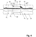
- Figures 2 , 3 , 4 and 5 show enlargements of the coupling between the male end 8 on the first drill rod 4 and the female end 12 on the second drill rod 10 for different embodiments of the present inventions, not all reference numbers are marked on each figure but are relevant to each of the figures.
- Figure 2 shows one embodiment of the present invention wherein there is a "shoulder contact” between the first drill rod 4 and the second drill rod 10 and wherein D 1 is greater than D 3 .
- Figure 3 shows another embodiment of the present invention wherein there is a "bottom contact" between the first drill rod 4 and the second drill rod 10 and wherein D 1 is greater than D 3 .
- Figure 4 shows another embodiment of the present invention wherein there is a "shoulder contact” between the first drill rod 4 and the second drill rod 10 and wherein D 1 is the same as D 3 .
- Figure 5 shows another embodiment of the present invention wherein there is a "shoulder contact” between the first drill rod 4 and the second drill rod 10 wherein D 1 is the same as D 3 .
- the male end 8 is provided with a spigot 29 comprising a non-threaded shank 30 positioned axially between the main length section 6 and a male thread 32.
- the female end 12 comprises a hollow mounting sleeve 36 that is internally threaded to form a female thread 38 and an internal cavity that extends axially from an axially rearward end 14.
- the longitudinal alignment of the respective male 32 and female 38 threads is substantially parallel to the longitudinal axis 28 of the first and second drill string rods 4, 10 such that the alignment of the overlap is substantially parallel to the longitudinal axis 28.
- the male thread 32 and female thread 38 engage one another to form a secure thread coupling to interconnect the drill rods 4, 10.
- the male end 8 and the female end 12 are helically threaded and comprise between two and seven complete helical turns.
- An internal bore 40 extends axially through the main length section 6 and the spigot 29 of uniform diameter.
- a coupling region 18 is formed where the male end 8 axially overlaps with the female end 12 from its axially rearward end 14 to an inner most female thread 16.
- the coupling region 18 has an axial length L 1 .
- a thread clearance area 20 is formed adjacent to the inner most female thread 16, in the area between the inner most female thread 16 and an axial inner wall 22 of the female end 12.
- the thread clearance area 20 typically has a region where the internal diameter of the cavity within the mounting sleeve 36 is at its greatest and / or is greater than the internal diameter of the cavity within the mounting sleeve 36 surrounding the inner most female thread 16.
- a strengthened region 24 is formed over a portion of the coupling region 18 by increasing the thickness of the wall of the mounting sleeve 36 over only a portion of its length.
- the mounting sleeve 36 has a first wall thickness T 1 at the axial rearward end 14 and a second wall thickness T 2 in the strengthened region 24, wherein T 2 > T 1 .
- T 2 is between 1-10% greater than T 1 .
- the thicknesses are measured between the peripheral edge 44 of the mounting sleeve 36 and the internal wall 52 of the cavity within the mounting sleeve 36. If the internal wall 52 is threaded in that region the measurement is taken from a trough 46 of the female thread 38.
- the mounting sleeve 36 has a first region 64 having a first outer skirt diameter, D 1 , at the axial rearward end 14 and a second outer skirt diameter, D 2 , along the strengthened region 24.
- the strengthened region 24 is positioned along part of the axial length between the axially rearward end 14 and the main length section 6 on the female end 12.
- the outer skirt diameter, D 2 , of the strengthened region 24 is at least 1-10% greater, preferably between 0.1 to 10 mm greater, than the outer skirt diameter D 1 of the axially rearward end most surface 14 of the female end 12.
- the strengthened region 24 is centred around an intersection 26 between the inner most female thread 16 and the thread clearance area 20.
- the strengthened region 24 is typically made from the same steel grade as the rest of the mounting sleeve 36 but could also be made from a different steel grade.
- the strengthened region 24 has a length L 2 .
- the strengthened region 24 extends at least along the length of the inner most female thread 16 or at least along the length of the thread clearance area 20 or at least along the length of both the inner most female thread 16 and the thread clearance area 20.
- the strengthened region 24 extends along at least the length of two thread turns from the inner most female thread 16.
- the strengthened region 24 extends along at least the length of two thread turns from the inner most female thread 16 and the thread clearance area 20.
- the female end 12 has a thread pitch length, L 3 .
- the length L 2 of the strengthened region is at least the length of one thread pitch length L 3 .
- the strengthened region 24 does not extend across the length of a first female thread 48, more preferably the strengthened region 24 does not extend across the length of the first female thread 48 and a second female thread 50.
- the region of the mounting sleeve 36 having the first, outer skirt diameter, D 1 extends across at least the length of the first female thread 48, preferably along the length of the first female thread 48 and the second female thread 50.
- L 2 is between 0.2 to 0.8 times the length of the coupling region L 1 .
- L 2 covers at least 10% of the length of the female thread 38, preferably at least 25%, more preferably at least 50% of the threads.
- L 1 does not cover more than 90% of the threads, more preferably not more than 75% of the threads.
- the main section 6 of the drill string has an outside skirt diameter, D 3 .
- the outer skirt diameter, D 1 , of the axially rearward end 14 of the female end 12 could be greater than the outside skirt diameter D 3 of the main section 6.
- the outer skirt diameter, D 1 , of the axially rearward end most surface 14 of the female end 12 is the same as the outside skirt diameter, D 3 , of the main section 6.
- the strengthened region 24 extends to the transition section 42. Alternatively, the strengthened region 24 ends before the start of the transition section 42.
- the strengthened region 24 extends to the internal bore 40 in the main length section.
- the contact between the first drill rod 4 and the second drill rod 10 could either be a "shoulder contact” or a "bottom contact”.
- a shoulder 56 on the male end 8 contacts an axially end most surface 58 on the female end 12, so that the transfer of energy happens before the threads 32,38.
- the axially end most surface 60 on the male end 8 contacts the axial inner wall 22 of the female end 12 to transfer the energy.
- Either type of contact can be combined with either D 1 be either greater or the same as D 3 .
- Figures 6 shows a stress image of the drill string coupling known in the prior art where no strengthened region 24 has been added.
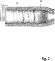
- Figure 7 shows a stress image of the drill string coupling according to the present invention where the strengthened section 24 has been added in the manner shown in figure 2 .
- the stress images were captured using the Dang van criterion using rotating bending as the load case.
- the risk for failure is increased as the value of the Dang van criterion in decreased.
- darker colours mean higher risk for failure.
- the exact dimensions of the strengthened region 24 are adapted to suit the type of rock and size of hole being drilled.
- the dimensions of the strengthened region 24 are selected so that during the drilling operation the strengthened region 24 wears away so that eventually the outer skirt diameter of the mounting sleeve 36 is substantially uniform and therefore the flushing efficiency of the rock drillings is returned to normal.
- the length and position of the strengthened region 24 it is important to consider the position where there is the highest stress and then position the strengthened region 24 to reinforce the location of highest stress.
Landscapes
- Engineering & Computer Science (AREA)
- Life Sciences & Earth Sciences (AREA)
- Geology (AREA)
- Mining & Mineral Resources (AREA)
- Mechanical Engineering (AREA)
- Physics & Mathematics (AREA)
- Environmental & Geological Engineering (AREA)
- Fluid Mechanics (AREA)
- General Life Sciences & Earth Sciences (AREA)
- Geochemistry & Mineralogy (AREA)
- Earth Drilling (AREA)
Abstract
Description
- The present invention relates to a drill string coupling for connecting individual elongate drill string members and in particular, although not exclusively, to a strengthened female coupling.
- Percussion drilling is used to create a long borehole via a plurality of elongate drill string rods coupled together end-to-end by interconnected male and female threads. The well-established technique breaks rock by hammering impacts transferred from the rock drill bit, mounted at one end of the drill string, to the rock at the bottom of the borehole. Typically, the energy required to break the rock is generated by a hydraulically driven piston that contacts the end of the drill string (via a shank adaptor) to create a stress (or shock) wave that propagates through the drill string and ultimately to the base rock level. Conventional male and female threaded couplings are described in
US 4,332,502 ;US 4,398,756 ;US 4,687,368 andDE 2800887 . - When the male and female threaded ends of neighbouring drill rods are coupled to create the drill string, the joint is typically subjected to bending forces during drilling from the stress waves that propagate the drill string. These bending moments fatigue the coupling and lead to breakage within the threaded portion of the joint. The drill coupling will fail by the coupling either eventually becoming worn out, which is predictable, or fail prematurely due to high stress waves which is unpredictable and causes increased down time for the user.
- Therefore, it is desirable to increase the strength of the coupling to improve the fatigue resistance of the coupling so that the chance of premature failure from high shock waves and bending loads is reduced. Known designs to increase the strength of the coupling are to increase the wall thickness of the female thread, however the problem with this is that then the space left to remove debris from the inside the drill hole is reduced and / or the minimum range of hole size that can be drilled is increased, therefore limiting the capability of the tooling. Alternatively, the male end of the coupling could be decreased in size, however the draw back with this design is that now the male end has been weakened and may fail prematurely. One known design is disclosed in
EP1511911B1 , whereby the male and female threads have a trapezoidal shape and the threads have a conical inclination along their length. The disadvantage of this design is that it is not readily adaptable to known assemblies and it requires modifications to be made to both the bit and the shank which adds additional costs. - Consequently, there is a need for an alternative design that increases the strength of the coupling, without reducing the ability to remove debris from inside the drill hole which is easily adaptable to known assemblies, without the need for further modifications to be made to other parts.
- It is an objective of this invention to provide a novel and improved percussive drill string coupling assembly.
- The objective is achieved by providing a drill string for percussive drilling comprising; a first elongate percussive drill rod having and a main section and an externally threaded male end; a second elongate percussive drill rod having a main section and a female end comprising an internally threaded mounting sleeve; wherein the male and female ends have respective threads for percussive drilling to enable the male end to be secured inside the female end such that an axial length from an axially rearward end on the female end to an end most female thread on the female end overlaps axially with the male end to form a coupling region; wherein a thread clearance area is formed adjacent to the end most female thread in the region between the end most female thread and an axial inner wall of the female end; characterized in that: the mounting sleeve has a first region having a first outer skirt diameter, D1, at the axially rearward end and a second outer skirt diameter, D2, along part of the axial length between the axially rearward end and the main section forming a strengthened region; wherein D2 is greater than D1.
- Advantageously, by only increasing the outer skirt diameter in the strengthened region both a reduction in stress in the coupling region can be achieved without significantly adversely affecting the efficiency of the debris removal. Advantageously, this design increases the lifetime of drill rods in cases where premature failures occur, thus making a more fail-safe product.
- Preferably, the length, L2, of the strengthened region extends at least along the length of the inner most female thread. The thread exit is a weak part of the joint and is where the high stresses build up. Therefore, it is advantageous to reinforce the coupling in this region.
- Preferably, length, L2, of the strengthened region extends at least along the length of the thread clearance area. The thread exit is a weak part of the joint and is where the high stresses build up. Therefore, it is advantageous to reinforce the coupling in this region.
- Preferably, the length, L2 of the strengthened region extends at least along the length of two thread turns from the inner most female thread. Advantageously, this will add further support to reinforce the coupling.
- Preferably, the first region of the mounting sleeve having the first outer skirt diameter, D1, extends across at least the length of the least a first female thread. In other words, preferably, the strengthened region ends before the position of the first female thread, preferably before the second female thread so that the flushing of the drill hole is not limited too much.
- Preferably, the length, L2 of the strengthened region is between 0.2 and 0.8 times the length of the axial length, L1 of the coupling region. If the length of the strengthened region is less than 0.2 times the length of the coupling region the benefit of the strengthening will not be gained. If the length of the strengthened region is greater than 0.8 times the length of the coupling region the efficiency in clearing the drilled hole of rock cuttings would be reduced. The length of the strengthen region is selected to suit different sizes of drills rods and different types of coupling.
- Optionally, the strengthened region extends to a transition section that extends between the mounting sleeve and the main length section. The end position of the strengthened region should be optimised depending on the drilling assembly, it may be advantageous that the strengthened region extends as far as the transition section for some designs to provide reinforcement to this region.
- The female end has a thread pitch length, L3, preferably the length, L2 of the strengthened region is at least the length of one thread pitch length, L3. Advantageously, the strengthened section will be sufficiently long to provide a substantial reinforcement.
- Preferably, the outer skirt diameter, D2 of the strengthened region is between 1-10% greater than the outer skirt diameter, D1 at the axially rearward end of the female end. The thickness of the strengthened region will depend on the size of the hole being drilled. If the outer skirt diameter of the strengthened region is at least 1% greater than the outer skirt diameter of the female end at the end most surface so that the coupling region is sufficiently increased, but no more than 10% greater so that the efficiency of the flushing in the drill hole is not compromised too much.
- Preferably, the outer skirt diameter, D2, of the strengthened region is between 0.1 to 10 mm greater than the outer skirt diameter, D1, at the axially rearward end of the female end. Advantageously, the presence of larger cross section in the strengthened region provides reinforcement at the critical location to reduce the level of stress in the most fragile part of the coupling region. The increased outer skirt diameter of the strengthened region will increase the fatigue resistance of the drill string rod components. If D2 is less than 0.1 mm greater than D1, then the benefit of the level of stress in the coupling region will not be significantly reduced. Generally, increasing the difference between D2 and D1 will increase the fatigue resistance. If D2 is more than 10 mm greater than D1 there will be a detrimental effect of the efficiency of the debris removal in the drilled hole. When drilling abrasive rock, the steel body of the drill string rods wears down due to the sliding contact with the rock and from the cuttings being flushed out of the hole. The reinforcement in the strengthened region will eventually get worn down to the normal outer skirt diameter and so then the passageway for the cutting will revert to normal. The addition of the strengthened region will advantageously increase the lifetime of the drill string rods and reduce the likelihood of premature failure. The most preferred outer skirt diameter, D1 will depend on the size of the hole being used, the size of the drill rods and the type of coupling.
- Preferably, the mounting sleeve has a first wall thickness, T1, at the axial rearward end and a second wall thickness, T2, in the strengthened region, wherein T2 > T1. Preferably, the inner dimensions inside the cavity of the female end are kept unchanged. The increase in outer skirt diameter in the strengthened region is created by increasing the wall thickness of the female end in this region. This is advantageous as then there is no reduction to the strength of the male end of the coupling, which could also lead to premature failure.
- Preferably, the strengthened region is centred around an intersection between the end most female thread and the thread clearance area. Advantageously, this targets the strengthening to the weakest point of the coupling.
- Preferably, the male end and the female end are helically threaded and comprise between two and seven complete helical turns. Advantageously, this range of the complete helical turns provides the best balance between coupling strength and cost.
- Optionally, the main section of the drill string has an outside skirt diameter, D3, wherein the outer skirt diameter, D1, of the axially rearward end of the female end is greater than the outside skirt diameter, D3, of the main section. This type of arrangement would be used for a guiding tube.
- Alternatively, the main section of the drill rod has an outside skirt diameter, D3, wherein the outer skirt diameter, D1, of the axially rearward end most surface of the female end is the same as the outside skirt diameter, D3, of the main section. This type of arrangement would be used for a drill tube.
- Another aspect of the present invention is a threaded coupling for connecting percussive drill rods to form a percussive drill string, the coupling comprising: a first elongate percussive drill rod having and a main section and an externally threaded male end; a second elongate percussive drill rod having a main section and a female end comprising an internally threaded mounting sleeve; wherein the male and female ends have respective threads for percussive drilling to enable the male end to be secured inside the female end such that an axial length, L1, from an axially rearward end on the female end to an end most female thread on the female end overlap axially with the male end to form a coupling region; wherein a thread clearance area is formed adjacent to the end most female thread in the region between the end most female thread and an axial inner wall of the female end; characterized in that: the mounting sleeve has a first region having a first outer skirt diameter, D1, at the axially rearward end and a second outer skirt diameter, D2, along part of the axial length between the axially rearward end and the main section forming a strengthened region; wherein D2 is greater than D1.
- A specific implementation of the present invention will now be described, by way of example only, and with reference to the accompanying drawings in which:
-
Figure 1 : is an external view of a drill string formed from a plurality of drill rods connected end-to-end by cooperated male and female threaded couplings. -
Figure 2 : is a cross section of the coupling between two drill rods showing the strengthened region for a shoulder contact connection where D1 is greater than D3. -
Figure 3 : is a cross section of the coupling between two drill rods showing the strengthened region for a bottom contact connection where D1 is greater than D3. -
Figure 4 : is a cross section of the coupling between two drill rods showing the strengthened region for a shoulder contact connection where D1 is the same as D3. -
Figure 5 : is a cross section of the coupling between two drill rods showing the strengthened region for a bottom contact connection where D1 is the same as D3. -
Figure 6 : is a stress analysis image of the coupling according to the prior art wherein there is no strengthened region added. -
Figure 7 : is a stress analysis image of the coupling according to the present invention where a strengthened region has been added. -
Figure 1 shows the coupling between a first elongatepercussive drill rod 4 and a second elongatepercussive drill rod 10 forming part of adrill string 2. Adrill string 2 may consist of a number of such rods that are screwed together to increase the length of thedrill string 2. Thedrill string 2 is attached to a drill bit at one end (not shown) and a shank adapter (not shown) at the other end which are also joined by means of corresponding screw threads. Each of thedrill rods main length section 6 that is terminated at one end by amale end 8 and at a second opposite end by afemale end 12 having alongitudinal axis 28. The coupling is created between themale end 8 on thefirst drill rod 4 and thefemale end 12 on thesecond drill rod 10. -
Figures 2 ,3 ,4 and5 show enlargements of the coupling between themale end 8 on thefirst drill rod 4 and thefemale end 12 on thesecond drill rod 10 for different embodiments of the present inventions, not all reference numbers are marked on each figure but are relevant to each of the figures.Figure 2 shows one embodiment of the present invention wherein there is a "shoulder contact" between thefirst drill rod 4 and thesecond drill rod 10 and wherein D1 is greater than D3.Figure 3 shows another embodiment of the present invention wherein there is a "bottom contact" between thefirst drill rod 4 and thesecond drill rod 10 and wherein D1 is greater than D3.Figure 4 shows another embodiment of the present invention wherein there is a "shoulder contact" between thefirst drill rod 4 and thesecond drill rod 10 and wherein D1 is the same as D3.Figure 5 shows another embodiment of the present invention wherein there is a "shoulder contact" between thefirst drill rod 4 and thesecond drill rod 10 wherein D1 is the same as D3. - The
male end 8 is provided with aspigot 29 comprising anon-threaded shank 30 positioned axially between themain length section 6 and amale thread 32. Thefemale end 12 comprises a hollow mountingsleeve 36 that is internally threaded to form afemale thread 38 and an internal cavity that extends axially from an axiallyrearward end 14. The longitudinal alignment of therespective male 32 and female 38 threads is substantially parallel to thelongitudinal axis 28 of the first and seconddrill string rods longitudinal axis 28. Themale thread 32 andfemale thread 38 engage one another to form a secure thread coupling to interconnect thedrill rods male end 8 and thefemale end 12 are helically threaded and comprise between two and seven complete helical turns. Aninternal bore 40 extends axially through themain length section 6 and thespigot 29 of uniform diameter. - A
coupling region 18 is formed where themale end 8 axially overlaps with thefemale end 12 from its axially rearward end 14 to an inner mostfemale thread 16. Thecoupling region 18 has an axial length L1. Athread clearance area 20 is formed adjacent to the inner mostfemale thread 16, in the area between the inner mostfemale thread 16 and an axialinner wall 22 of thefemale end 12. Thethread clearance area 20 typically has a region where the internal diameter of the cavity within the mountingsleeve 36 is at its greatest and / or is greater than the internal diameter of the cavity within the mountingsleeve 36 surrounding the inner mostfemale thread 16. A strengthenedregion 24 is formed over a portion of thecoupling region 18 by increasing the thickness of the wall of the mountingsleeve 36 over only a portion of its length. The mountingsleeve 36 has a first wall thickness T1 at the axialrearward end 14 and a second wall thickness T2 in the strengthenedregion 24, wherein T2 > T1. Preferably, T2 is between 1-10% greater than T1. The thicknesses are measured between theperipheral edge 44 of the mountingsleeve 36 and theinternal wall 52 of the cavity within the mountingsleeve 36. If theinternal wall 52 is threaded in that region the measurement is taken from atrough 46 of thefemale thread 38. This means that the mountingsleeve 36 has afirst region 64 having a first outer skirt diameter, D1, at the axialrearward end 14 and a second outer skirt diameter, D2, along the strengthenedregion 24. The strengthenedregion 24 is positioned along part of the axial length between the axiallyrearward end 14 and themain length section 6 on thefemale end 12. The outer skirt diameter, D2, of the strengthenedregion 24 is at least 1-10% greater, preferably between 0.1 to 10 mm greater, than the outer skirt diameter D1 of the axially rearward endmost surface 14 of thefemale end 12. Preferably, the strengthenedregion 24 is centred around anintersection 26 between the inner mostfemale thread 16 and thethread clearance area 20. The strengthenedregion 24 is typically made from the same steel grade as the rest of the mountingsleeve 36 but could also be made from a different steel grade. - The strengthened
region 24 has a length L2. The strengthenedregion 24 extends at least along the length of the inner mostfemale thread 16 or at least along the length of thethread clearance area 20 or at least along the length of both the inner mostfemale thread 16 and thethread clearance area 20. Optionally, the strengthenedregion 24 extends along at least the length of two thread turns from the inner mostfemale thread 16. Optionally, the strengthenedregion 24 extends along at least the length of two thread turns from the inner mostfemale thread 16 and thethread clearance area 20. - The
female end 12 has a thread pitch length, L3. Optionally, the length L2 of the strengthened region is at least the length of one thread pitch length L3. - The strengthened
region 24 does not extend across the length of a firstfemale thread 48, more preferably the strengthenedregion 24 does not extend across the length of the firstfemale thread 48 and a secondfemale thread 50. In other words, the region of the mountingsleeve 36 having the first, outer skirt diameter, D1, extends across at least the length of the firstfemale thread 48, preferably along the length of the firstfemale thread 48 and the secondfemale thread 50. Preferably, L2 is between 0.2 to 0.8 times the length of the coupling region L1. Preferably, L2 covers at least 10% of the length of thefemale thread 38, preferably at least 25%, more preferably at least 50% of the threads. Preferably L1 does not cover more than 90% of the threads, more preferably not more than 75% of the threads. - The
main section 6 of the drill string has an outside skirt diameter, D3. The outer skirt diameter, D1, of the axially rearward end 14 of thefemale end 12 could be greater than the outside skirt diameter D3 of themain section 6. Alternatively, the outer skirt diameter, D1, of the axially rearward endmost surface 14 of thefemale end 12 is the same as the outside skirt diameter, D3, of themain section 6. - A
transition section 42 is formed between the mountingsleeve 36 and themain length section 8 on thefemale end 12. If D1 is greater than D3, the transition section radially flares from themain length section 6 to the mountingsleeve 36. If D1 is the same as D3, the transition section has a substantially uniform diameter. Typically for couplings where D1 = D3, acircumferal groove 54 is formed on the peripheral edge of thedrill rod 10 from the manufacturing or welding process, located between thefemale end 12 and themain length section 6, and therefore thetransition section 42 in this case can be considered to be the region transitioning between thegroove 54 and the mountingsleeve 36. Optionally, the strengthenedregion 24 extends to thetransition section 42. Alternatively, the strengthenedregion 24 ends before the start of thetransition section 42. Optionally, the strengthenedregion 24 extends to theinternal bore 40 in the main length section. - The contact between the
first drill rod 4 and thesecond drill rod 10 could either be a "shoulder contact" or a "bottom contact". For the "shoulder contact", as shown infigures 2 and4 , ashoulder 56 on themale end 8 contacts an axially endmost surface 58 on thefemale end 12, so that the transfer of energy happens before thethreads figures 3 and5 , the axially endmost surface 60 on themale end 8 contacts the axialinner wall 22 of thefemale end 12 to transfer the energy. Either type of contact can be combined with either D1 be either greater or the same as D3. -
Figures 6 shows a stress image of the drill string coupling known in the prior art where no strengthenedregion 24 has been added.Figure 7 shows a stress image of the drill string coupling according to the present invention where the strengthenedsection 24 has been added in the manner shown infigure 2 . The stress images were captured using the Dang van criterion using rotating bending as the load case. The risk for failure is increased as the value of the Dang van criterion in decreased. Thus, darker colours mean higher risk for failure. By comparingfigure 7 to figure 6 it can be seen that the risk of failure occurring decreases when the strengthenedregion 24 is added. The stress analysis was captured using implicit analysis in LS-Dyna and the Dang van criterion is extracted using the nCode software. - The exact dimensions of the strengthened
region 24 are adapted to suit the type of rock and size of hole being drilled. The dimensions of the strengthenedregion 24 are selected so that during the drilling operation the strengthenedregion 24 wears away so that eventually the outer skirt diameter of the mountingsleeve 36 is substantially uniform and therefore the flushing efficiency of the rock drillings is returned to normal. When designing the length and position of the strengthenedregion 24 it is important to consider the position where there is the highest stress and then position the strengthenedregion 24 to reinforce the location of highest stress.
Claims (15)
- A drill string (2) for percussive drilling comprising:a first elongate percussive drill rod (4) having and a main section (6) and an externally threaded male end (8);a second elongate percussive drill rod (10) having a main section (6) and a female end (12) comprising an internally threaded mounting sleeve (36);wherein the male (8) and female (12) ends have respective threads for percussive drilling to enable the male end (8) to be secured inside the female end (12) such that an axial length (L1) from an axially rearward end (14) on the female end (12) to an end most female thread (16) on the female end (12) overlaps axially with the male end (8) to form a coupling region (18);wherein a thread clearance area (20) is formed adjacent to the end most female thread (16) in the region between the end most female thread (16) and an axial inner wall (22) of the female end (12);characterized in that:the mounting sleeve (36) has a first region (64) having a first outer skirt diameter (D1) at the axially rearward end (14) and having second outer skirt diameter (D2) along part of the axial length between the axially rearward end (14) and the main section (6) forming a strengthened region (24);wherein D2 is greater than D1.
- The drill string (2) according to claim 1, wherein the length (L2) of the strengthened region (24) extends at least along the length of the inner most female thread (16).
- The drill string (2) according to claim 1 or claim 2, wherein the length (L2) of the strengthened region (24) extends at least along the length of the thread clearance area (20).
- The drill string (2) according to any of the previous claims, wherein the length (L2) of the strengthened region (24) extends at least along the length of two thread turns from the inner most female thread (16).
- The drill string (2) according to any of the previous claims, wherein the first region (64) of the mounting sleeve (36) having the first outer skirt diameter (D1) extends across at least the length a first female thread (48).
- The drill string (2) according to any of the previous claims, wherein the length (L2) of the strengthened region (24) is between 0.2 and 0.8 times the length of the axial length (L1) of the coupling region (18).
- The drill string (2) according to any of the previous claims, wherein the strengthened region (24) extends to a transition section (42) that extends between the mounting sleeve (36) and the main length section (8).
- The drill string (2) according to any of the previous claims, wherein the female end (12) has a thread pitch length (L3) and wherein the length (L2) of the strengthened region is at least the length of one thread pitch length (L3).
- The drill string (2) according to any of the previous claims, wherein the outer skirt diameter (D2) of the strengthened region (24) is between 1-10% greater than the outer skirt diameter (D1) at the axially rearward end (14) of the female end (12).
- The drill string (2) according to any of claims 1-8, wherein the outer skirt diameter (D2) of the strengthened region (24) is at least 0.1 to 10 mm greater than the outer skirt diameter (D1) at the axially rearward end (14) of the female end (12).
- The drill string (2) according to any of the previous claims, wherein the mounting sleeve (36) has a first wall thickness (T1) at the axial rearward end (14) and a second wall thickness (T2) in the strengthened region (24), wherein T2 > T1.
- The drill string (2) according to any of the previous claims, wherein the strengthened region (24) is centred around an intersection (26) between the end most female thread (16) and the thread clearance area (20).
- The drill string (2) according to any of the any of the previous claims, wherein the main section (6) of the drill string has an outside skirt diameter (D3), wherein the outer skirt diameter (D1) of the axially rearward end (14) of the female end (12) is greater than the outside skirt diameter (D3) of the main section (6).
- The drill string (2) according to any of claims 1-12, wherein the main section (6) of the drill rod has an outside skirt diameter (D3), wherein the outer skirt diameter (D1) of the axially rearward end most surface (14) of the female end (12) is the same as the outside skirt diameter (D3) of the main section (6).
- A threaded coupling for connecting percussive drill rods to form a percussive drill string, the coupling comprising:a first elongate percussive drill rod (4) having and a main section (6) and an externally threaded male end (8);a second elongate percussive drill rod (10) having a main section (6) and a female end (12) comprising an internally threaded mounting sleeve (36);wherein the male (8) and female (12) ends have respective threads for percussive drilling to enable the male end (8) to be secured inside the female end (12) such that an axial length (L1) from an axially rearward end (14) on the female end (12) to an end most female thread (16) on the female end (12) overlap axially with the male end (8) to form a coupling region (18);wherein a thread clearance area (20) is formed adjacent to the end most female thread (16) in the region between the end most female thread (16) and an axial inner wall (22) of the female end (12);characterized in that:the mounting sleeve (36) has a first region (64) having a first outer skirt diameter (D1) at the axially rearward end (14) and a second outer skirt diameter (D2) along part of the axial length between the axially rearward end (14) and the main section (6) forming a strengthened region (24);wherein D2 is greater than D1.
Priority Applications (3)
| Application Number | Priority Date | Filing Date | Title |
|---|---|---|---|
| EP19208106.5A EP3819458B1 (en) | 2019-11-08 | 2019-11-08 | Strengthened percussive drill string female coupling |
| PCT/EP2020/081180 WO2021089727A1 (en) | 2019-11-08 | 2020-11-05 | Strengthened percussive drill string female coupling |
| KR1020227018577A KR20220092588A (en) | 2019-11-08 | 2020-11-05 | Reinforced Impact Drill String Female Coupling |
Applications Claiming Priority (1)
| Application Number | Priority Date | Filing Date | Title |
|---|---|---|---|
| EP19208106.5A EP3819458B1 (en) | 2019-11-08 | 2019-11-08 | Strengthened percussive drill string female coupling |
Publications (2)
| Publication Number | Publication Date |
|---|---|
| EP3819458A1 true EP3819458A1 (en) | 2021-05-12 |
| EP3819458B1 EP3819458B1 (en) | 2022-10-19 |
Family
ID=68501500
Family Applications (1)
| Application Number | Title | Priority Date | Filing Date |
|---|---|---|---|
| EP19208106.5A Not-in-force EP3819458B1 (en) | 2019-11-08 | 2019-11-08 | Strengthened percussive drill string female coupling |
Country Status (3)
| Country | Link |
|---|---|
| EP (1) | EP3819458B1 (en) |
| KR (1) | KR20220092588A (en) |
| WO (1) | WO2021089727A1 (en) |
Citations (9)
| Publication number | Priority date | Publication date | Assignee | Title |
|---|---|---|---|---|
| US3485271A (en) * | 1966-09-30 | 1969-12-23 | Mccreary Tire & Rubber Co | Protector for casings,pipes and other cylindrical objects |
| DE2800887A1 (en) | 1977-01-11 | 1978-07-13 | Padley & Venables Ltd | DRILL ROD CONSISTING OF RELEASABLE ELEMENTS |
| US4398756A (en) | 1980-09-15 | 1983-08-16 | Vallourec, S. A. | Cylindro-conical pipe joint |
| US4509777A (en) * | 1982-11-01 | 1985-04-09 | Dril-Quip Inc. | Weld-on casing connector |
| US4687368A (en) | 1985-04-04 | 1987-08-18 | Santrade Limited | Thread structure for percussion rock drilling |
| EP2710217A1 (en) * | 2011-05-20 | 2014-03-26 | Atlas Copco Secoroc AB | Thread device, thread joint and drill string component for percussive rock drilling |
| EP1511911B1 (en) | 2002-05-22 | 2014-11-19 | Atlas Copco Secoroc AB | A thread joint for a drill string for percussive rock-drilling |
| EP2845993A1 (en) * | 2013-09-09 | 2015-03-11 | Sandvik Intellectual Property AB | Energy Transmission Efficient Drill String Coupling |
| WO2019206484A1 (en) * | 2018-04-25 | 2019-10-31 | Peter Kroll | System and protector for protecting an end of a pipe |
-
2019
- 2019-11-08 EP EP19208106.5A patent/EP3819458B1/en not_active Not-in-force
-
2020
- 2020-11-05 WO PCT/EP2020/081180 patent/WO2021089727A1/en not_active Ceased
- 2020-11-05 KR KR1020227018577A patent/KR20220092588A/en not_active Withdrawn
Patent Citations (10)
| Publication number | Priority date | Publication date | Assignee | Title |
|---|---|---|---|---|
| US3485271A (en) * | 1966-09-30 | 1969-12-23 | Mccreary Tire & Rubber Co | Protector for casings,pipes and other cylindrical objects |
| DE2800887A1 (en) | 1977-01-11 | 1978-07-13 | Padley & Venables Ltd | DRILL ROD CONSISTING OF RELEASABLE ELEMENTS |
| US4332502A (en) | 1977-01-11 | 1982-06-01 | Padley & Venables Limited | Apparatus for use in drilling |
| US4398756A (en) | 1980-09-15 | 1983-08-16 | Vallourec, S. A. | Cylindro-conical pipe joint |
| US4509777A (en) * | 1982-11-01 | 1985-04-09 | Dril-Quip Inc. | Weld-on casing connector |
| US4687368A (en) | 1985-04-04 | 1987-08-18 | Santrade Limited | Thread structure for percussion rock drilling |
| EP1511911B1 (en) | 2002-05-22 | 2014-11-19 | Atlas Copco Secoroc AB | A thread joint for a drill string for percussive rock-drilling |
| EP2710217A1 (en) * | 2011-05-20 | 2014-03-26 | Atlas Copco Secoroc AB | Thread device, thread joint and drill string component for percussive rock drilling |
| EP2845993A1 (en) * | 2013-09-09 | 2015-03-11 | Sandvik Intellectual Property AB | Energy Transmission Efficient Drill String Coupling |
| WO2019206484A1 (en) * | 2018-04-25 | 2019-10-31 | Peter Kroll | System and protector for protecting an end of a pipe |
Also Published As
| Publication number | Publication date |
|---|---|
| KR20220092588A (en) | 2022-07-01 |
| WO2021089727A1 (en) | 2021-05-14 |
| EP3819458B1 (en) | 2022-10-19 |
Similar Documents
| Publication | Publication Date | Title |
|---|---|---|
| EP2845992B1 (en) | Drill string with bend resistant coupling | |
| EP4386247A2 (en) | Drill rod or adaptor with strengthened spigot coupling | |
| US11808086B2 (en) | Drill string rod | |
| EP3819458B1 (en) | Strengthened percussive drill string female coupling | |
| EP4047179B1 (en) | Elliptical design for shank adapters | |
| EP4172455B1 (en) | Thread clearance | |
| EP3971385B1 (en) | Drill string joint design | |
| EP4473185B1 (en) | Drilling component | |
| AU2021298830B2 (en) | Thread clearance | |
| RU2787856C1 (en) | Drill string rod and drilling system | |
| OA21320A (en) | Elliptical design for shank adapters. | |
| OA20379A (en) | Drill string rod. |
Legal Events
| Date | Code | Title | Description |
|---|---|---|---|
| PUAI | Public reference made under article 153(3) epc to a published international application that has entered the european phase |
Free format text: ORIGINAL CODE: 0009012 |
|
| STAA | Information on the status of an ep patent application or granted ep patent |
Free format text: STATUS: THE APPLICATION HAS BEEN PUBLISHED |
|
| AK | Designated contracting states |
Kind code of ref document: A1 Designated state(s): AL AT BE BG CH CY CZ DE DK EE ES FI FR GB GR HR HU IE IS IT LI LT LU LV MC MK MT NL NO PL PT RO RS SE SI SK SM TR |
|
| STAA | Information on the status of an ep patent application or granted ep patent |
Free format text: STATUS: REQUEST FOR EXAMINATION WAS MADE |
|
| 17P | Request for examination filed |
Effective date: 20211112 |
|
| RBV | Designated contracting states (corrected) |
Designated state(s): AL AT BE BG CH CY CZ DE DK EE ES FI FR GB GR HR HU IE IS IT LI LT LU LV MC MK MT NL NO PL PT RO RS SE SI SK SM TR |
|
| GRAP | Despatch of communication of intention to grant a patent |
Free format text: ORIGINAL CODE: EPIDOSNIGR1 |
|
| STAA | Information on the status of an ep patent application or granted ep patent |
Free format text: STATUS: GRANT OF PATENT IS INTENDED |
|
| GRAJ | Information related to disapproval of communication of intention to grant by the applicant or resumption of examination proceedings by the epo deleted |
Free format text: ORIGINAL CODE: EPIDOSDIGR1 |
|
| STAA | Information on the status of an ep patent application or granted ep patent |
Free format text: STATUS: REQUEST FOR EXAMINATION WAS MADE |
|
| INTG | Intention to grant announced |
Effective date: 20220404 |
|
| GRAP | Despatch of communication of intention to grant a patent |
Free format text: ORIGINAL CODE: EPIDOSNIGR1 |
|
| STAA | Information on the status of an ep patent application or granted ep patent |
Free format text: STATUS: GRANT OF PATENT IS INTENDED |
|
| INTC | Intention to grant announced (deleted) | ||
| INTG | Intention to grant announced |
Effective date: 20220525 |
|
| GRAS | Grant fee paid |
Free format text: ORIGINAL CODE: EPIDOSNIGR3 |
|
| GRAA | (expected) grant |
Free format text: ORIGINAL CODE: 0009210 |
|
| STAA | Information on the status of an ep patent application or granted ep patent |
Free format text: STATUS: THE PATENT HAS BEEN GRANTED |
|
| AK | Designated contracting states |
Kind code of ref document: B1 Designated state(s): AL AT BE BG CH CY CZ DE DK EE ES FI FR GB GR HR HU IE IS IT LI LT LU LV MC MK MT NL NO PL PT RO RS SE SI SK SM TR |
|
| REG | Reference to a national code |
Ref country code: GB Ref legal event code: FG4D |
|
| REG | Reference to a national code |
Ref country code: CH Ref legal event code: EP |
|
| REG | Reference to a national code |
Ref country code: IE Ref legal event code: FG4D |
|
| REG | Reference to a national code |
Ref country code: DE Ref legal event code: R096 Ref document number: 602019020758 Country of ref document: DE |
|
| REG | Reference to a national code |
Ref country code: AT Ref legal event code: REF Ref document number: 1525650 Country of ref document: AT Kind code of ref document: T Effective date: 20221115 |
|
| REG | Reference to a national code |
Ref country code: SE Ref legal event code: TRGR |
|
| REG | Reference to a national code |
Ref country code: LT Ref legal event code: MG9D |
|
| REG | Reference to a national code |
Ref country code: NL Ref legal event code: MP Effective date: 20221019 |
|
| PG25 | Lapsed in a contracting state [announced via postgrant information from national office to epo] |
Ref country code: NL Free format text: LAPSE BECAUSE OF FAILURE TO SUBMIT A TRANSLATION OF THE DESCRIPTION OR TO PAY THE FEE WITHIN THE PRESCRIBED TIME-LIMIT Effective date: 20221019 |
|
| PG25 | Lapsed in a contracting state [announced via postgrant information from national office to epo] |
Ref country code: PT Free format text: LAPSE BECAUSE OF FAILURE TO SUBMIT A TRANSLATION OF THE DESCRIPTION OR TO PAY THE FEE WITHIN THE PRESCRIBED TIME-LIMIT Effective date: 20230220 Ref country code: NO Free format text: LAPSE BECAUSE OF FAILURE TO SUBMIT A TRANSLATION OF THE DESCRIPTION OR TO PAY THE FEE WITHIN THE PRESCRIBED TIME-LIMIT Effective date: 20230119 Ref country code: LT Free format text: LAPSE BECAUSE OF FAILURE TO SUBMIT A TRANSLATION OF THE DESCRIPTION OR TO PAY THE FEE WITHIN THE PRESCRIBED TIME-LIMIT Effective date: 20221019 Ref country code: FI Free format text: LAPSE BECAUSE OF FAILURE TO SUBMIT A TRANSLATION OF THE DESCRIPTION OR TO PAY THE FEE WITHIN THE PRESCRIBED TIME-LIMIT Effective date: 20221019 Ref country code: ES Free format text: LAPSE BECAUSE OF FAILURE TO SUBMIT A TRANSLATION OF THE DESCRIPTION OR TO PAY THE FEE WITHIN THE PRESCRIBED TIME-LIMIT Effective date: 20221019 |
|
| PG25 | Lapsed in a contracting state [announced via postgrant information from national office to epo] |
Ref country code: RS Free format text: LAPSE BECAUSE OF FAILURE TO SUBMIT A TRANSLATION OF THE DESCRIPTION OR TO PAY THE FEE WITHIN THE PRESCRIBED TIME-LIMIT Effective date: 20221019 Ref country code: PL Free format text: LAPSE BECAUSE OF FAILURE TO SUBMIT A TRANSLATION OF THE DESCRIPTION OR TO PAY THE FEE WITHIN THE PRESCRIBED TIME-LIMIT Effective date: 20221019 Ref country code: LV Free format text: LAPSE BECAUSE OF FAILURE TO SUBMIT A TRANSLATION OF THE DESCRIPTION OR TO PAY THE FEE WITHIN THE PRESCRIBED TIME-LIMIT Effective date: 20221019 Ref country code: IS Free format text: LAPSE BECAUSE OF FAILURE TO SUBMIT A TRANSLATION OF THE DESCRIPTION OR TO PAY THE FEE WITHIN THE PRESCRIBED TIME-LIMIT Effective date: 20230219 Ref country code: HR Free format text: LAPSE BECAUSE OF FAILURE TO SUBMIT A TRANSLATION OF THE DESCRIPTION OR TO PAY THE FEE WITHIN THE PRESCRIBED TIME-LIMIT Effective date: 20221019 Ref country code: GR Free format text: LAPSE BECAUSE OF FAILURE TO SUBMIT A TRANSLATION OF THE DESCRIPTION OR TO PAY THE FEE WITHIN THE PRESCRIBED TIME-LIMIT Effective date: 20230120 |
|
| REG | Reference to a national code |
Ref country code: DE Ref legal event code: R119 Ref document number: 602019020758 Country of ref document: DE |
|
| REG | Reference to a national code |
Ref country code: CH Ref legal event code: PL |
|
| REG | Reference to a national code |
Ref country code: BE Ref legal event code: MM Effective date: 20221130 |
|
| PG25 | Lapsed in a contracting state [announced via postgrant information from national office to epo] |
Ref country code: SM Free format text: LAPSE BECAUSE OF FAILURE TO SUBMIT A TRANSLATION OF THE DESCRIPTION OR TO PAY THE FEE WITHIN THE PRESCRIBED TIME-LIMIT Effective date: 20221019 Ref country code: RO Free format text: LAPSE BECAUSE OF FAILURE TO SUBMIT A TRANSLATION OF THE DESCRIPTION OR TO PAY THE FEE WITHIN THE PRESCRIBED TIME-LIMIT Effective date: 20221019 Ref country code: MC Free format text: LAPSE BECAUSE OF FAILURE TO SUBMIT A TRANSLATION OF THE DESCRIPTION OR TO PAY THE FEE WITHIN THE PRESCRIBED TIME-LIMIT Effective date: 20221019 Ref country code: LI Free format text: LAPSE BECAUSE OF NON-PAYMENT OF DUE FEES Effective date: 20221130 Ref country code: EE Free format text: LAPSE BECAUSE OF FAILURE TO SUBMIT A TRANSLATION OF THE DESCRIPTION OR TO PAY THE FEE WITHIN THE PRESCRIBED TIME-LIMIT Effective date: 20221019 Ref country code: DK Free format text: LAPSE BECAUSE OF FAILURE TO SUBMIT A TRANSLATION OF THE DESCRIPTION OR TO PAY THE FEE WITHIN THE PRESCRIBED TIME-LIMIT Effective date: 20221019 Ref country code: CZ Free format text: LAPSE BECAUSE OF FAILURE TO SUBMIT A TRANSLATION OF THE DESCRIPTION OR TO PAY THE FEE WITHIN THE PRESCRIBED TIME-LIMIT Effective date: 20221019 Ref country code: CH Free format text: LAPSE BECAUSE OF NON-PAYMENT OF DUE FEES Effective date: 20221130 |
|
| PLBE | No opposition filed within time limit |
Free format text: ORIGINAL CODE: 0009261 |
|
| STAA | Information on the status of an ep patent application or granted ep patent |
Free format text: STATUS: NO OPPOSITION FILED WITHIN TIME LIMIT |
|
| PG25 | Lapsed in a contracting state [announced via postgrant information from national office to epo] |
Ref country code: SK Free format text: LAPSE BECAUSE OF FAILURE TO SUBMIT A TRANSLATION OF THE DESCRIPTION OR TO PAY THE FEE WITHIN THE PRESCRIBED TIME-LIMIT Effective date: 20221019 Ref country code: LU Free format text: LAPSE BECAUSE OF NON-PAYMENT OF DUE FEES Effective date: 20221108 Ref country code: AL Free format text: LAPSE BECAUSE OF FAILURE TO SUBMIT A TRANSLATION OF THE DESCRIPTION OR TO PAY THE FEE WITHIN THE PRESCRIBED TIME-LIMIT Effective date: 20221019 |
|
| 26N | No opposition filed |
Effective date: 20230720 |
|
| PG25 | Lapsed in a contracting state [announced via postgrant information from national office to epo] |
Ref country code: IE Free format text: LAPSE BECAUSE OF NON-PAYMENT OF DUE FEES Effective date: 20221108 Ref country code: DE Free format text: LAPSE BECAUSE OF NON-PAYMENT OF DUE FEES Effective date: 20230601 |
|
| PG25 | Lapsed in a contracting state [announced via postgrant information from national office to epo] |
Ref country code: SI Free format text: LAPSE BECAUSE OF FAILURE TO SUBMIT A TRANSLATION OF THE DESCRIPTION OR TO PAY THE FEE WITHIN THE PRESCRIBED TIME-LIMIT Effective date: 20221019 Ref country code: FR Free format text: LAPSE BECAUSE OF NON-PAYMENT OF DUE FEES Effective date: 20221219 Ref country code: BE Free format text: LAPSE BECAUSE OF NON-PAYMENT OF DUE FEES Effective date: 20221130 |
|
| REG | Reference to a national code |
Ref country code: AT Ref legal event code: UEP Ref document number: 1525650 Country of ref document: AT Kind code of ref document: T Effective date: 20221019 |
|
| PGFP | Annual fee paid to national office [announced via postgrant information from national office to epo] |
Ref country code: SE Payment date: 20231010 Year of fee payment: 5 |
|
| PG25 | Lapsed in a contracting state [announced via postgrant information from national office to epo] |
Ref country code: CY Free format text: LAPSE BECAUSE OF FAILURE TO SUBMIT A TRANSLATION OF THE DESCRIPTION OR TO PAY THE FEE WITHIN THE PRESCRIBED TIME-LIMIT Effective date: 20221019 |
|
| PG25 | Lapsed in a contracting state [announced via postgrant information from national office to epo] |
Ref country code: MK Free format text: LAPSE BECAUSE OF FAILURE TO SUBMIT A TRANSLATION OF THE DESCRIPTION OR TO PAY THE FEE WITHIN THE PRESCRIBED TIME-LIMIT Effective date: 20221019 Ref country code: IT Free format text: LAPSE BECAUSE OF FAILURE TO SUBMIT A TRANSLATION OF THE DESCRIPTION OR TO PAY THE FEE WITHIN THE PRESCRIBED TIME-LIMIT Effective date: 20221019 Ref country code: HU Free format text: LAPSE BECAUSE OF FAILURE TO SUBMIT A TRANSLATION OF THE DESCRIPTION OR TO PAY THE FEE WITHIN THE PRESCRIBED TIME-LIMIT; INVALID AB INITIO Effective date: 20191108 |
|
| GBPC | Gb: european patent ceased through non-payment of renewal fee |
Effective date: 20231108 |
|
| PG25 | Lapsed in a contracting state [announced via postgrant information from national office to epo] |
Ref country code: BG Free format text: LAPSE BECAUSE OF FAILURE TO SUBMIT A TRANSLATION OF THE DESCRIPTION OR TO PAY THE FEE WITHIN THE PRESCRIBED TIME-LIMIT Effective date: 20221019 |
|
| PG25 | Lapsed in a contracting state [announced via postgrant information from national office to epo] |
Ref country code: MT Free format text: LAPSE BECAUSE OF FAILURE TO SUBMIT A TRANSLATION OF THE DESCRIPTION OR TO PAY THE FEE WITHIN THE PRESCRIBED TIME-LIMIT Effective date: 20221019 |
|
| PG25 | Lapsed in a contracting state [announced via postgrant information from national office to epo] |
Ref country code: GB Free format text: LAPSE BECAUSE OF NON-PAYMENT OF DUE FEES Effective date: 20231108 |
|
| PG25 | Lapsed in a contracting state [announced via postgrant information from national office to epo] |
Ref country code: GB Free format text: LAPSE BECAUSE OF NON-PAYMENT OF DUE FEES Effective date: 20231108 |
|
| REG | Reference to a national code |
Ref country code: SE Ref legal event code: EUG |
|
| PG25 | Lapsed in a contracting state [announced via postgrant information from national office to epo] |
Ref country code: SE Free format text: LAPSE BECAUSE OF NON-PAYMENT OF DUE FEES Effective date: 20241109 |
|
| PG25 | Lapsed in a contracting state [announced via postgrant information from national office to epo] |
Ref country code: TR Free format text: LAPSE BECAUSE OF FAILURE TO SUBMIT A TRANSLATION OF THE DESCRIPTION OR TO PAY THE FEE WITHIN THE PRESCRIBED TIME-LIMIT Effective date: 20221019 |
|
| PG25 | Lapsed in a contracting state [announced via postgrant information from national office to epo] |
Ref country code: AT Free format text: LAPSE BECAUSE OF NON-PAYMENT OF DUE FEES Effective date: 20241108 |
|
| REG | Reference to a national code |
Ref country code: AT Ref legal event code: MM01 Ref document number: 1525650 Country of ref document: AT Kind code of ref document: T Effective date: 20241108 |
|
| PGFP | Annual fee paid to national office [announced via postgrant information from national office to epo] |
Ref country code: AT Payment date: 20260410 Year of fee payment: 5 |