EP3819428A1 - Divergent device for a molding platform - Google Patents
Divergent device for a molding platform Download PDFInfo
- Publication number
- EP3819428A1 EP3819428A1 EP19207750.1A EP19207750A EP3819428A1 EP 3819428 A1 EP3819428 A1 EP 3819428A1 EP 19207750 A EP19207750 A EP 19207750A EP 3819428 A1 EP3819428 A1 EP 3819428A1
- Authority
- EP
- European Patent Office
- Prior art keywords
- molding
- air chamber
- platform
- fluid
- divergent
- Prior art date
- Legal status (The legal status is an assumption and is not a legal conclusion. Google has not performed a legal analysis and makes no representation as to the accuracy of the status listed.)
- Withdrawn
Links
- 238000000465 moulding Methods 0.000 title claims abstract description 114
- 239000012530 fluid Substances 0.000 claims abstract description 72
- 238000007664 blowing Methods 0.000 claims description 28
- 239000002002 slurry Substances 0.000 description 6
- 238000004519 manufacturing process Methods 0.000 description 3
- 238000000034 method Methods 0.000 description 3
- 238000001035 drying Methods 0.000 description 2
- 238000007731 hot pressing Methods 0.000 description 2
- 238000009434 installation Methods 0.000 description 1
- 239000000463 material Substances 0.000 description 1
- 238000012986 modification Methods 0.000 description 1
- 230000004048 modification Effects 0.000 description 1
Images



Classifications
-
- D—TEXTILES; PAPER
- D21—PAPER-MAKING; PRODUCTION OF CELLULOSE
- D21J—FIBREBOARD; MANUFACTURE OF ARTICLES FROM CELLULOSIC FIBROUS SUSPENSIONS OR FROM PAPIER-MACHE
- D21J7/00—Manufacture of hollow articles from fibre suspensions or papier-mâché by deposition of fibres in or on a wire-net mould
Definitions
- the present invention relates to a divergent device for molding platform, and more particularly to a divergent device for molding platform which uses a fluid divider and a flow velocity adjustor to adjust a flow rate.
- paper products are one of the most used disposable products.
- manufacturers usually use a pulp molding machine for manufacturing the products.
- a plurality of molding dies 71 are usually provided on a molding platform 70, such that when the molding platform 70 is lowered and immersed into a slurry, air is supplied through a blowing and suction device and is introduced into the molding platform 70 via an air tube 72 at a specific position. Then the molding dies 71 are adhered with the pulp material in the slurry to form the paper products described above, and then after hot pressing, drying and other procedures, the finished paper products can be completed.
- the blowing and suction device supplies a fluid via the air tube 72 connected at the specific position
- the slurry at the specific position receives a stronger blowing force
- positions farther from the specific position e.g. surrounding positions within the molding platform
- the blowing and suction device provides a suction force of the fluid
- the suction force of the fluid close to the air tube 72 is stronger, while the suction force of the fluid received by positions farther from the air tube 72 is weaker. Therefore, after the pulp is adhered to each of the molding dies 71, the suction force of the fluid received by the molding dies 71 which are farther from the air tube 72 is weaker, so that the paper products formed of the pulp cannot be effectively dried.
- an object of the present invention is to provide a divergent device for molding platform, which mainly utilizes a fluid divider and a flow velocity adjustor to uniform and adjust a blowing force or a suction force of a fluid, so that the pulp can be uniformly adhered to each molding die, and paper products adhered to each of the molding dies can be effectively dried.
- the present invention provides a divergent device for molding platform, comprising:
- the divergent device for molding platform further comprises a flow velocity adjustor disposed in the molding air chamber capable of adjusting a flow rate of a fluid passing through the molding air chamber.
- the flow velocity adjustor is disposed with a plurality of adjustment holes, each of the adjustment holes is provided for the fluid to flow from the molding air chamber into the air chamber, or provided for the fluid to flow from the air chamber into the molding air chamber.
- a periphery of the fluid divider is connected to at least one connecting member, and the connecting member is connected to the platform and the molding template, so that the fluid divider is capable of moving on the connecting member to adjust the divergent distance.
- the air tube is connected to a blowing and suction device so that the blowing and suction device supplies a fluid to the air chamber via the air tube.
- a divergent device for molding platform of the present invention is mainly composed of a molding platform 10, at least one fluid divider 20, at least one molding die 30, and a flow velocity adjustor 40.
- the molding platform 10 is a working platform which can be raised and lowered, and is composed of a combination of a platform 11 and a molding template 12, so that an air chamber 13 is formed inside the molding platform 10.
- the platform 11 is connected to at least one air tube 50, and the air tube 50 communicates with the air chamber 13.
- the air tube 50 is connected to a blowing and suction device to provide a fluid (can be a blowing force or a suction force) through the blowing and suction device, and the blowing and suction device introduces the fluid into the air chamber 13 via the air tube 50.
- a fluid can be a blowing force or a suction force
- the fluid divider 20 is disposed inside the air chamber 13, and the fluid divider 20 is spaced apart from a junction of the platform 11 and the air tube 50 by a divergent distance SG; in this way, when the air tube 50 introduces the fluid into the air chamber 13, the fluid divider 20 is capable of slowing down a blowing force or a suction force of the fluid, so that the blowing force or the suction force of the fluid can be more evenly distributed to each position inside the air chamber 13.
- a size of the divergent distance SG is capable of determining an intensity of the blowing force or the suction force of the fluid affected by the fluid divider 20. Specifically, when the divergent distance SG is small, an installation position of the fluid divider 20 is made closer to the junction between the platform 11 and the air tube 50, in order to reduce an opening area of the air tube 50 for introducing the fluid into the air chamber 13, so that when the introduction amount is reduced, the blowing force or the suction force of the fluid can be slowed down; when the divergent distance SG is large, the fluid divider 20 is disposed at a position farther from the junction between the platform 11 and the air tube 50, in order to increase the opening area of the air tube 50 for introducing the fluid into the air chamber 13, so that when the introduction amount is large, the blowing force or the suction force of the fluid can be increased.
- the molding die 30 is mainly used for adhering with the pulp in a slurry. After the pulp is adhered on the molding die 30, a paper product is formed according to the molding die 30 by procedures such as hot pressing and drying.
- the molding die 30 is disposed on the molding template 12, and a molding air chamber 31 is disposed inside the molding die 30, and the molding air chamber 31 communicates with the air chamber 13. Thus, after the fluid enters into the air chamber 13, it is further introduced into the molding air chamber 31.
- the flow velocity adjustor 40 is disposed inside the molding air chamber 31, and is provided with a plurality of adjustment holes 41, each of the adjustment holes 41 is provided for the fluid to flow from the molding air chamber 31 into the air chamber 13, or is provided for the fluid to flow from the air chamber 13 into the molding air chamber 31.
- each of the adjustment holes 41 can be formed with different sizes and shapes (as shown in FIGS. 3A and 3B ) such that a flow rate of the fluid passing through the adjustment holes 41 on the left side for example is different from a flow rate of the fluid passing through the other adjustment holes 41 with different sizes and shapes on the right side, thereby a flow rate of the fluid at each position of the molding die 30 is adjusted according to a shape of the molding die 30.
- the fluid when the fluid is supplied by the blowing and suction device, the fluid first enters into the air chamber 13 through the air tube 50, and after the fluid divider 20 is used to slow down a flow rate of the fluid, the fluid is further introduced from the air chamber 13 into the molding air chamber 31.
- the fluid When the fluid is introduced into the molding air chamber 31, the fluid first passes through the flow velocity adjustor 40 to further adjust a flow rate of the fluid, and finally is introduced into the molding air chamber 31 in order to provide the blowing force or the suction force of the fluid.
- the pulp can be uniformly adhered to each of the molding dies 30, and the paper products on each of the molding dies 30 can be effectively dried.
- FIG. 5 is a schematic structural view of connecting members and the fluid divider of the divergent device for molding platform of the present invention.
- a periphery of the fluid divider 20 is connected to at least one connecting member 60.
- the connecting member 60 is connected to the platform 11 and the molding template 12, so that the fluid divider 20 is capable of moving on the connecting member 60 to adjust the divergent distance SG, in order to adjust the blowing force or the suction force of the fluid.
Landscapes
- Engineering & Computer Science (AREA)
- Manufacturing & Machinery (AREA)
- Paper (AREA)
Abstract
The present invention provides a divergent device for molding platform, which is mainly provided with a molding platform internally disposed with an air chamber, a bottom surface of the molding platform is connected with at least one air tube, and an interior of the molding platform and an interior of the air tube communicate with each other; at least one fluid divider disposed in the air chamber, and the fluid divider is spaced apart from a junction of the platform and the air tube by a divergent distance; at least one molding die disposed on a surface of the molding platform, a molding air chamber is disposed inside the molding die, and the molding air chamber communicates with the air chamber; and a flow velocity adjustor disposed in the molding air chamber capable of adjusting a flow rate of a fluid passing through the molding air chamber.
Description
- The present invention relates to a divergent device for molding platform, and more particularly to a divergent device for molding platform which uses a fluid divider and a flow velocity adjustor to adjust a flow rate.
- In daily life, paper products are one of the most used disposable products. For the effective manufacture of paper cups, paper bowls or other paper products, manufacturers usually use a pulp molding machine for manufacturing the products.
- As shown in
FIG. 1 , in the manufacture of paper products, a plurality ofmolding dies 71 are usually provided on amolding platform 70, such that when themolding platform 70 is lowered and immersed into a slurry, air is supplied through a blowing and suction device and is introduced into themolding platform 70 via anair tube 72 at a specific position. Then the molding dies 71 are adhered with the pulp material in the slurry to form the paper products described above, and then after hot pressing, drying and other procedures, the finished paper products can be completed. - However, when the blowing and suction device supplies a fluid via the
air tube 72 connected at the specific position, the slurry at the specific position receives a stronger blowing force, while positions farther from the specific position (e.g. surrounding positions within the molding platform) receive a weaker blowing force. Therefore, when the slurry is adhered to each of the molding dies 71 by the blowing force of the fluid, the amount of the pulp adhered to each of the molding dies 71 at different positions may be uneven due to the difference in the blowing force at each position. - On the contrary, when the blowing and suction device provides a suction force of the fluid, the suction force of the fluid close to the
air tube 72 is stronger, while the suction force of the fluid received by positions farther from theair tube 72 is weaker. Therefore, after the pulp is adhered to each of the molding dies 71, the suction force of the fluid received by themolding dies 71 which are farther from theair tube 72 is weaker, so that the paper products formed of the pulp cannot be effectively dried. - Thus, in order to improve the above drawbacks in the techniques of the prior art, related inventions are urgently needed to uniform and adjust the blowing force and suction force of the fluid effectively, so that the slurry can be uniformly adhered to each of the molding dies, and the paper products adhered to each of the molding dies can be effectively dried.
- In order to solve the problems disclosed above, an object of the present invention is to provide a divergent device for molding platform, which mainly utilizes a fluid divider and a flow velocity adjustor to uniform and adjust a blowing force or a suction force of a fluid, so that the pulp can be uniformly adhered to each molding die, and paper products adhered to each of the molding dies can be effectively dried.
- In order to achieve the above object, the present invention provides a divergent device for molding platform, comprising:
- a molding platform comprising a platform and a molding template, the platform being connected with the molding template such that an interior of the molding platform forming an air chamber, the platform being connected to at least one air tube, and an interior of the platform and an interior of the air tube communicating with each other;
- at least one fluid divider disposed in the air chamber, and the fluid divider being spaced apart from a junction of the platform and the air tube by a divergent distance; and
- at least one molding die disposed on the molding template, a molding air chamber being disposed inside the molding die, and the molding air chamber communicating with the air chamber.
- Preferably, the divergent device for molding platform further comprises a flow velocity adjustor disposed in the molding air chamber capable of adjusting a flow rate of a fluid passing through the molding air chamber.
- Preferably, the flow velocity adjustor is disposed with a plurality of adjustment holes, each of the adjustment holes is provided for the fluid to flow from the molding air chamber into the air chamber, or provided for the fluid to flow from the air chamber into the molding air chamber.
- Preferably, a periphery of the fluid divider is connected to at least one connecting member, and the connecting member is connected to the platform and the molding template, so that the fluid divider is capable of moving on the connecting member to adjust the divergent distance.
- Preferably, the air tube is connected to a blowing and suction device so that the blowing and suction device supplies a fluid to the air chamber via the air tube.
-
-
FIG. 1 is a schematic structural view of the prior art; -
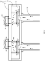
FIG. 2 is a schematic structural view of a divergent device for molding platform of the present invention; -
FIG. 3A is a schematic view of a first embodiment of adjustment holes of the divergent device for molding platform of the present invention; -
FIG. 3B is a schematic view of a second embodiment of the adjustment holes of the divergent device for molding platform of the present invention; -
FIG. 4 is a schematic view of airflow of the divergent device for molding platform of the present invention; and -
FIG. 5 is a schematic structural view of connecting members and a fluid divider of the divergent device for molding platform of the present invention. - In order to make the objects, the technical solutions and the advantages of the present invention more comprehensible, the present invention will be further described in detail with reference to the accompanying drawings and embodiments. It is understandable that the specific embodiments described herein are merely illustrative of the present invention and are not intended to limit the present invention. Hereinafter, the present invention will be further described with reference to the drawings.
- Please refer to
FIG. 2 to FIG. 4 , which are schematic structural view, schematic view of first and second embodiments of adjustment holes, and schematic view of airflow of a divergent device for molding platform of the present invention. As shown in the drawings, a divergent device for molding platform of the present invention is mainly composed of amolding platform 10, at least onefluid divider 20, at least onemolding die 30, and aflow velocity adjustor 40. Wherein themolding platform 10 is a working platform which can be raised and lowered, and is composed of a combination of aplatform 11 and amolding template 12, so that anair chamber 13 is formed inside themolding platform 10. Theplatform 11 is connected to at least oneair tube 50, and theair tube 50 communicates with theair chamber 13. In addition, theair tube 50 is connected to a blowing and suction device to provide a fluid (can be a blowing force or a suction force) through the blowing and suction device, and the blowing and suction device introduces the fluid into theair chamber 13 via theair tube 50. - The
fluid divider 20 is disposed inside theair chamber 13, and thefluid divider 20 is spaced apart from a junction of theplatform 11 and theair tube 50 by a divergent distance SG; in this way, when theair tube 50 introduces the fluid into theair chamber 13, thefluid divider 20 is capable of slowing down a blowing force or a suction force of the fluid, so that the blowing force or the suction force of the fluid can be more evenly distributed to each position inside theair chamber 13. - A size of the divergent distance SG is capable of determining an intensity of the blowing force or the suction force of the fluid affected by the
fluid divider 20. Specifically, when the divergent distance SG is small, an installation position of thefluid divider 20 is made closer to the junction between theplatform 11 and theair tube 50, in order to reduce an opening area of theair tube 50 for introducing the fluid into theair chamber 13, so that when the introduction amount is reduced, the blowing force or the suction force of the fluid can be slowed down; when the divergent distance SG is large, thefluid divider 20 is disposed at a position farther from the junction between theplatform 11 and theair tube 50, in order to increase the opening area of theair tube 50 for introducing the fluid into theair chamber 13, so that when the introduction amount is large, the blowing force or the suction force of the fluid can be increased. - The
molding die 30 is mainly used for adhering with the pulp in a slurry. After the pulp is adhered on the molding die 30, a paper product is formed according to themolding die 30 by procedures such as hot pressing and drying. Themolding die 30 is disposed on themolding template 12, and amolding air chamber 31 is disposed inside themolding die 30, and themolding air chamber 31 communicates with theair chamber 13. Thus, after the fluid enters into theair chamber 13, it is further introduced into themolding air chamber 31. - The
flow velocity adjustor 40 is disposed inside themolding air chamber 31, and is provided with a plurality ofadjustment holes 41, each of theadjustment holes 41 is provided for the fluid to flow from themolding air chamber 31 into theair chamber 13, or is provided for the fluid to flow from theair chamber 13 into themolding air chamber 31. Wherein each of theadjustment holes 41 can be formed with different sizes and shapes (as shown inFIGS. 3A and 3B ) such that a flow rate of the fluid passing through theadjustment holes 41 on the left side for example is different from a flow rate of the fluid passing through theother adjustment holes 41 with different sizes and shapes on the right side, thereby a flow rate of the fluid at each position of themolding die 30 is adjusted according to a shape of themolding die 30. - Therefore, when the fluid is supplied by the blowing and suction device, the fluid first enters into the
air chamber 13 through theair tube 50, and after thefluid divider 20 is used to slow down a flow rate of the fluid, the fluid is further introduced from theair chamber 13 into themolding air chamber 31. When the fluid is introduced into themolding air chamber 31, the fluid first passes through theflow velocity adjustor 40 to further adjust a flow rate of the fluid, and finally is introduced into themolding air chamber 31 in order to provide the blowing force or the suction force of the fluid. Therefore, by evening and adjusting the blowing force or the suction force of the fluid through thefluid divider 20 and theflow velocity adjustor 40, the pulp can be uniformly adhered to each of the molding dies 30, and the paper products on each of the molding dies 30 can be effectively dried. - Please refer to
FIG. 5 , which is a schematic structural view of connecting members and the fluid divider of the divergent device for molding platform of the present invention. As shown in the drawing, a periphery of thefluid divider 20 is connected to at least one connectingmember 60. The connectingmember 60 is connected to theplatform 11 and themolding template 12, so that thefluid divider 20 is capable of moving on the connectingmember 60 to adjust the divergent distance SG, in order to adjust the blowing force or the suction force of the fluid. - While the preferred embodiments of the invention have been set forth for the purpose of disclosure, modifications of the disclosed embodiments of the invention as well as other embodiments thereof may occur to those skilled in the art. Accordingly, the appended claims are intended to cover all embodiments which do not depart from the spirit and scope of the invention.
Claims (8)
- A divergent device for molding platform, comprising:a molding platform comprising a platform and a molding template, the platform being connected with the molding template such that an interior of the molding platform forming an air chamber, the platform being connected to at least one air tube, and an interior of the platform and an interior of the air tube communicating with each other;at least one fluid divider disposed in the air chamber, and the fluid divider being spaced apart from a junction of the platform and the air tube by a divergent distance; andat least one molding die disposed on the molding template, a molding air chamber being disposed inside the molding die, and the molding air chamber communicating with the air chamber.
- The divergent device for molding platform as claimed in claim 1, further comprising a flow velocity adjustor disposed inside the molding air chamber capable of adjusting a flow rate of a fluid passing through the molding air chamber.
- The divergent device for molding platform as claimed in claim 2, wherein the flow velocity adjustor is disposed with a plurality of adjustment holes, each of the adjustment holes is provided for the fluid to flow from the molding air chamber into the air chamber, or provided for the fluid to flow from the air chamber into the molding air chamber.
- The divergent device for molding platform as claimed in any one of claims 1 to 3, wherein a periphery of the fluid divider is connected to at least one connecting member, and the connecting member is connected to the platform and the molding template, so that the fluid divider is capable of moving on the connecting member to adjust the divergent distance.
- The divergent device for molding platform as claimed in any one of claims 1 to 3, wherein the air tube is connected to a blowing and suction device so that the blowing and suction device supplies a fluid to the air chamber via the air tube.
- A divergent device for molding platform, comprising:a molding platform comprising a platform and a molding template, the platform being connected with the molding template such that an interior of the molding platform forming an air chamber, the platform being connected to at least one air tube, and an interior of the platform and an interior of the air tube communicating with each other;a molding die disposed on the molding template, a molding air chamber being disposed inside the molding die, and the molding air chamber communicating with the air chamber; anda flow velocity adjustor disposed inside the molding air chamber capable of adjusting a flow rate of a fluid passing through the molding air chamber.
- The divergent device for molding platform as claimed in claim 6, wherein the flow velocity adjustor is disposed with a plurality of adjustment holes, each of the adjustment holes is provided for the fluid to flow from the molding air chamber into the air chamber, or provided for the fluid to flow from the air chamber into the molding air chamber.
- The divergent device for molding platform as claimed in claim 1 or 7, wherein the air tube is connected to a blowing and suction device so that the blowing and suction device supplies a fluid to the air chamber via the air tube.
Priority Applications (1)
| Application Number | Priority Date | Filing Date | Title |
|---|---|---|---|
| EP19207750.1A EP3819428A1 (en) | 2019-11-07 | 2019-11-07 | Divergent device for a molding platform |
Applications Claiming Priority (1)
| Application Number | Priority Date | Filing Date | Title |
|---|---|---|---|
| EP19207750.1A EP3819428A1 (en) | 2019-11-07 | 2019-11-07 | Divergent device for a molding platform |
Publications (1)
| Publication Number | Publication Date |
|---|---|
| EP3819428A1 true EP3819428A1 (en) | 2021-05-12 |
Family
ID=68502944
Family Applications (1)
| Application Number | Title | Priority Date | Filing Date |
|---|---|---|---|
| EP19207750.1A Withdrawn EP3819428A1 (en) | 2019-11-07 | 2019-11-07 | Divergent device for a molding platform |
Country Status (1)
| Country | Link |
|---|---|
| EP (1) | EP3819428A1 (en) |
Citations (2)
| Publication number | Priority date | Publication date | Assignee | Title |
|---|---|---|---|---|
| US3023806A (en) * | 1957-02-12 | 1962-03-06 | Willis Reynolds Corp | Machine for forming molded fibre articles |
| US6352617B1 (en) * | 2000-02-09 | 2002-03-05 | Vincent Lee | Pulp-forming mold-releasing machine |
-
2019
- 2019-11-07 EP EP19207750.1A patent/EP3819428A1/en not_active Withdrawn
Patent Citations (2)
| Publication number | Priority date | Publication date | Assignee | Title |
|---|---|---|---|---|
| US3023806A (en) * | 1957-02-12 | 1962-03-06 | Willis Reynolds Corp | Machine for forming molded fibre articles |
| US6352617B1 (en) * | 2000-02-09 | 2002-03-05 | Vincent Lee | Pulp-forming mold-releasing machine |
Similar Documents
| Publication | Publication Date | Title |
|---|---|---|
| EP2757194A3 (en) | Pulp moulded lid with non-reticulated inner and outer surfaces and process of manufacturing the same | |
| EP3819428A1 (en) | Divergent device for a molding platform | |
| JP4099147B2 (en) | Manufacturing method of paper-molded product and heating press device | |
| CN110983866A (en) | A kind of pulp molding product negative draft molding equipment, system and process | |
| JP3420237B2 (en) | Modular forming tool for use in machines for producing shells or thin stock plates from pulp material | |
| CN109629342B (en) | Pulp suction mold for pulp molding with longitudinal through grooves | |
| CN112681018A (en) | Forming platform shunting device | |
| CN207646064U (en) | Glass aspheric lenses secondary press mold | |
| CN201295973Y (en) | Vacuum chuck | |
| CN114232390B (en) | Control method of molding equipment | |
| CN105058756A (en) | Carrier band forming device and method | |
| CN210477553U (en) | Plastic film production facility | |
| TW202108357A (en) | Forming platform diversion device including forming platform, at least one diverting body, at least one forming die, and a flow rate adjusting body | |
| JP4579280B2 (en) | Stamping device for cooked rice food | |
| CN206401297U (en) | A kind of board structure with degassing function | |
| CN111041898B (en) | System for solving problem of back surface pulp hanging of paper pulp molded product | |
| CN208263254U (en) | A kind of mold for suppressing drum seal gasket | |
| CN209869684U (en) | Quick drying device is used in carton production printing | |
| JP2009040000A (en) | Vacuum molding device | |
| CN108623134A (en) | Novel hot-bending machine and glass bending production line | |
| CN220079578U (en) | A wet paper plastic preparation device and a wet paper plastic preparation system | |
| CN207770610U (en) | A stamping die | |
| CN220013218U (en) | Anti-wrinkle processing mold for paper and plastic products | |
| CN211268609U (en) | A square food extrusion die | |
| CN205045985U (en) | Air current guider |
Legal Events
| Date | Code | Title | Description |
|---|---|---|---|
| PUAI | Public reference made under article 153(3) epc to a published international application that has entered the european phase |
Free format text: ORIGINAL CODE: 0009012 |
|
| STAA | Information on the status of an ep patent application or granted ep patent |
Free format text: STATUS: THE APPLICATION HAS BEEN PUBLISHED |
|
| AK | Designated contracting states |
Kind code of ref document: A1 Designated state(s): AL AT BE BG CH CY CZ DE DK EE ES FI FR GB GR HR HU IE IS IT LI LT LU LV MC MK MT NL NO PL PT RO RS SE SI SK SM TR |
|
| STAA | Information on the status of an ep patent application or granted ep patent |
Free format text: STATUS: THE APPLICATION IS DEEMED TO BE WITHDRAWN |
|
| 18D | Application deemed to be withdrawn |
Effective date: 20211113 |