EP3819157A1 - An entertainment system for a vehicle including a sound emitting module - Google Patents
An entertainment system for a vehicle including a sound emitting module Download PDFInfo
- Publication number
- EP3819157A1 EP3819157A1 EP19208035.6A EP19208035A EP3819157A1 EP 3819157 A1 EP3819157 A1 EP 3819157A1 EP 19208035 A EP19208035 A EP 19208035A EP 3819157 A1 EP3819157 A1 EP 3819157A1
- Authority
- EP
- European Patent Office
- Prior art keywords
- sound emitting
- entertainment system
- windshield
- emitting module
- vehicle
- Prior art date
- Legal status (The legal status is an assumption and is not a legal conclusion. Google has not performed a legal analysis and makes no representation as to the accuracy of the status listed.)
- Granted
Links
Images


Classifications
-
- H—ELECTRICITY
- H04—ELECTRIC COMMUNICATION TECHNIQUE
- H04R—LOUDSPEAKERS, MICROPHONES, GRAMOPHONE PICK-UPS OR LIKE ACOUSTIC ELECTROMECHANICAL TRANSDUCERS; ELECTRIC HEARING AIDS; PUBLIC ADDRESS SYSTEMS
- H04R1/00—Details of transducers, loudspeakers or microphones
- H04R1/20—Arrangements for obtaining desired frequency or directional characteristics
- H04R1/32—Arrangements for obtaining desired frequency or directional characteristics for obtaining desired directional characteristic only
- H04R1/40—Arrangements for obtaining desired frequency or directional characteristics for obtaining desired directional characteristic only by combining a number of identical transducers
- H04R1/403—Arrangements for obtaining desired frequency or directional characteristics for obtaining desired directional characteristic only by combining a number of identical transducers loud-speakers
-
- B—PERFORMING OPERATIONS; TRANSPORTING
- B60—VEHICLES IN GENERAL
- B60K—ARRANGEMENT OR MOUNTING OF PROPULSION UNITS OR OF TRANSMISSIONS IN VEHICLES; ARRANGEMENT OR MOUNTING OF PLURAL DIVERSE PRIME-MOVERS IN VEHICLES; AUXILIARY DRIVES FOR VEHICLES; INSTRUMENTATION OR DASHBOARDS FOR VEHICLES; ARRANGEMENTS IN CONNECTION WITH COOLING, AIR INTAKE, GAS EXHAUST OR FUEL SUPPLY OF PROPULSION UNITS IN VEHICLES
- B60K35/00—Instruments specially adapted for vehicles; Arrangement of instruments in or on vehicles
- B60K35/20—Output arrangements, i.e. from vehicle to user, associated with vehicle functions or specially adapted therefor
- B60K35/26—Output arrangements, i.e. from vehicle to user, associated with vehicle functions or specially adapted therefor using acoustic output
-
- B—PERFORMING OPERATIONS; TRANSPORTING
- B60—VEHICLES IN GENERAL
- B60K—ARRANGEMENT OR MOUNTING OF PROPULSION UNITS OR OF TRANSMISSIONS IN VEHICLES; ARRANGEMENT OR MOUNTING OF PLURAL DIVERSE PRIME-MOVERS IN VEHICLES; AUXILIARY DRIVES FOR VEHICLES; INSTRUMENTATION OR DASHBOARDS FOR VEHICLES; ARRANGEMENTS IN CONNECTION WITH COOLING, AIR INTAKE, GAS EXHAUST OR FUEL SUPPLY OF PROPULSION UNITS IN VEHICLES
- B60K35/00—Instruments specially adapted for vehicles; Arrangement of instruments in or on vehicles
- B60K35/20—Output arrangements, i.e. from vehicle to user, associated with vehicle functions or specially adapted therefor
- B60K35/21—Output arrangements, i.e. from vehicle to user, associated with vehicle functions or specially adapted therefor using visual output, e.g. blinking lights or matrix displays
- B60K35/22—Display screens
-
- B—PERFORMING OPERATIONS; TRANSPORTING
- B60—VEHICLES IN GENERAL
- B60K—ARRANGEMENT OR MOUNTING OF PROPULSION UNITS OR OF TRANSMISSIONS IN VEHICLES; ARRANGEMENT OR MOUNTING OF PLURAL DIVERSE PRIME-MOVERS IN VEHICLES; AUXILIARY DRIVES FOR VEHICLES; INSTRUMENTATION OR DASHBOARDS FOR VEHICLES; ARRANGEMENTS IN CONNECTION WITH COOLING, AIR INTAKE, GAS EXHAUST OR FUEL SUPPLY OF PROPULSION UNITS IN VEHICLES
- B60K35/00—Instruments specially adapted for vehicles; Arrangement of instruments in or on vehicles
- B60K35/60—Instruments characterised by their location or relative disposition in or on vehicles
-
- B—PERFORMING OPERATIONS; TRANSPORTING
- B60—VEHICLES IN GENERAL
- B60K—ARRANGEMENT OR MOUNTING OF PROPULSION UNITS OR OF TRANSMISSIONS IN VEHICLES; ARRANGEMENT OR MOUNTING OF PLURAL DIVERSE PRIME-MOVERS IN VEHICLES; AUXILIARY DRIVES FOR VEHICLES; INSTRUMENTATION OR DASHBOARDS FOR VEHICLES; ARRANGEMENTS IN CONNECTION WITH COOLING, AIR INTAKE, GAS EXHAUST OR FUEL SUPPLY OF PROPULSION UNITS IN VEHICLES
- B60K37/00—Dashboards
- B60K37/20—Dashboard panels
-
- B—PERFORMING OPERATIONS; TRANSPORTING
- B60—VEHICLES IN GENERAL
- B60R—VEHICLES, VEHICLE FITTINGS, OR VEHICLE PARTS, NOT OTHERWISE PROVIDED FOR
- B60R11/00—Arrangements for holding or mounting articles, not otherwise provided for
- B60R11/02—Arrangements for holding or mounting articles, not otherwise provided for for radio sets, television sets, telephones, or the like; Arrangement of controls thereof
- B60R11/0217—Arrangements for holding or mounting articles, not otherwise provided for for radio sets, television sets, telephones, or the like; Arrangement of controls thereof for loud-speakers
-
- B—PERFORMING OPERATIONS; TRANSPORTING
- B60—VEHICLES IN GENERAL
- B60R—VEHICLES, VEHICLE FITTINGS, OR VEHICLE PARTS, NOT OTHERWISE PROVIDED FOR
- B60R11/00—Arrangements for holding or mounting articles, not otherwise provided for
- B60R11/02—Arrangements for holding or mounting articles, not otherwise provided for for radio sets, television sets, telephones, or the like; Arrangement of controls thereof
- B60R11/0229—Arrangements for holding or mounting articles, not otherwise provided for for radio sets, television sets, telephones, or the like; Arrangement of controls thereof for displays, e.g. cathodic tubes
-
- G—PHYSICS
- G09—EDUCATION; CRYPTOGRAPHY; DISPLAY; ADVERTISING; SEALS
- G09G—ARRANGEMENTS OR CIRCUITS FOR CONTROL OF INDICATING DEVICES USING STATIC MEANS TO PRESENT VARIABLE INFORMATION
- G09G5/00—Control arrangements or circuits for visual indicators common to cathode-ray tube indicators and other visual indicators
- G09G5/02—Control arrangements or circuits for visual indicators common to cathode-ray tube indicators and other visual indicators characterised by the way in which colour is displayed
-
- H—ELECTRICITY
- H04—ELECTRIC COMMUNICATION TECHNIQUE
- H04R—LOUDSPEAKERS, MICROPHONES, GRAMOPHONE PICK-UPS OR LIKE ACOUSTIC ELECTROMECHANICAL TRANSDUCERS; ELECTRIC HEARING AIDS; PUBLIC ADDRESS SYSTEMS
- H04R1/00—Details of transducers, loudspeakers or microphones
- H04R1/02—Casings; Cabinets ; Supports therefor; Mountings therein
- H04R1/023—Screens for loudspeakers
-
- H—ELECTRICITY
- H04—ELECTRIC COMMUNICATION TECHNIQUE
- H04R—LOUDSPEAKERS, MICROPHONES, GRAMOPHONE PICK-UPS OR LIKE ACOUSTIC ELECTROMECHANICAL TRANSDUCERS; ELECTRIC HEARING AIDS; PUBLIC ADDRESS SYSTEMS
- H04R1/00—Details of transducers, loudspeakers or microphones
- H04R1/02—Casings; Cabinets ; Supports therefor; Mountings therein
- H04R1/025—Arrangements for fixing loudspeaker transducers, e.g. in a box, furniture
-
- H—ELECTRICITY
- H04—ELECTRIC COMMUNICATION TECHNIQUE
- H04R—LOUDSPEAKERS, MICROPHONES, GRAMOPHONE PICK-UPS OR LIKE ACOUSTIC ELECTROMECHANICAL TRANSDUCERS; ELECTRIC HEARING AIDS; PUBLIC ADDRESS SYSTEMS
- H04R1/00—Details of transducers, loudspeakers or microphones
- H04R1/20—Arrangements for obtaining desired frequency or directional characteristics
- H04R1/22—Arrangements for obtaining desired frequency or directional characteristics for obtaining desired frequency characteristic only
- H04R1/26—Spatial arrangements of separate transducers responsive to two or more frequency ranges
-
- H—ELECTRICITY
- H04—ELECTRIC COMMUNICATION TECHNIQUE
- H04R—LOUDSPEAKERS, MICROPHONES, GRAMOPHONE PICK-UPS OR LIKE ACOUSTIC ELECTROMECHANICAL TRANSDUCERS; ELECTRIC HEARING AIDS; PUBLIC ADDRESS SYSTEMS
- H04R1/00—Details of transducers, loudspeakers or microphones
- H04R1/20—Arrangements for obtaining desired frequency or directional characteristics
- H04R1/32—Arrangements for obtaining desired frequency or directional characteristics for obtaining desired directional characteristic only
- H04R1/34—Arrangements for obtaining desired frequency or directional characteristics for obtaining desired directional characteristic only by using a single transducer with sound reflecting, diffracting, directing or guiding means
- H04R1/345—Arrangements for obtaining desired frequency or directional characteristics for obtaining desired directional characteristic only by using a single transducer with sound reflecting, diffracting, directing or guiding means for loudspeakers
-
- H—ELECTRICITY
- H04—ELECTRIC COMMUNICATION TECHNIQUE
- H04R—LOUDSPEAKERS, MICROPHONES, GRAMOPHONE PICK-UPS OR LIKE ACOUSTIC ELECTROMECHANICAL TRANSDUCERS; ELECTRIC HEARING AIDS; PUBLIC ADDRESS SYSTEMS
- H04R3/00—Circuits for transducers
- H04R3/12—Circuits for transducers for distributing signals to two or more loudspeakers
-
- H—ELECTRICITY
- H04—ELECTRIC COMMUNICATION TECHNIQUE
- H04R—LOUDSPEAKERS, MICROPHONES, GRAMOPHONE PICK-UPS OR LIKE ACOUSTIC ELECTROMECHANICAL TRANSDUCERS; ELECTRIC HEARING AIDS; PUBLIC ADDRESS SYSTEMS
- H04R5/00—Stereophonic arrangements
- H04R5/02—Spatial or constructional arrangements of loudspeakers
-
- B—PERFORMING OPERATIONS; TRANSPORTING
- B60—VEHICLES IN GENERAL
- B60J—WINDOWS, WINDSCREENS, NON-FIXED ROOFS, DOORS, OR SIMILAR DEVICES FOR VEHICLES; REMOVABLE EXTERNAL PROTECTIVE COVERINGS SPECIALLY ADAPTED FOR VEHICLES
- B60J1/00—Windows; Windscreens; Accessories therefor
- B60J1/002—Windows; Windscreens; Accessories therefor with means for clear vision, e.g. anti-frost or defog panes, rain shields
-
- B—PERFORMING OPERATIONS; TRANSPORTING
- B60—VEHICLES IN GENERAL
- B60K—ARRANGEMENT OR MOUNTING OF PROPULSION UNITS OR OF TRANSMISSIONS IN VEHICLES; ARRANGEMENT OR MOUNTING OF PLURAL DIVERSE PRIME-MOVERS IN VEHICLES; AUXILIARY DRIVES FOR VEHICLES; INSTRUMENTATION OR DASHBOARDS FOR VEHICLES; ARRANGEMENTS IN CONNECTION WITH COOLING, AIR INTAKE, GAS EXHAUST OR FUEL SUPPLY OF PROPULSION UNITS IN VEHICLES
- B60K2360/00—Indexing scheme associated with groups B60K35/00 or B60K37/00 relating to details of instruments or dashboards
- B60K2360/60—Structural details of dashboards or instruments
- B60K2360/65—Features of dashboards
- B60K2360/658—Dashboard parts used as air ducts
-
- B—PERFORMING OPERATIONS; TRANSPORTING
- B60—VEHICLES IN GENERAL
- B60K—ARRANGEMENT OR MOUNTING OF PROPULSION UNITS OR OF TRANSMISSIONS IN VEHICLES; ARRANGEMENT OR MOUNTING OF PLURAL DIVERSE PRIME-MOVERS IN VEHICLES; AUXILIARY DRIVES FOR VEHICLES; INSTRUMENTATION OR DASHBOARDS FOR VEHICLES; ARRANGEMENTS IN CONNECTION WITH COOLING, AIR INTAKE, GAS EXHAUST OR FUEL SUPPLY OF PROPULSION UNITS IN VEHICLES
- B60K2360/00—Indexing scheme associated with groups B60K35/00 or B60K37/00 relating to details of instruments or dashboards
- B60K2360/77—Instrument locations other than the dashboard
- B60K2360/785—Instrument locations other than the dashboard on or in relation to the windshield or windows
-
- B—PERFORMING OPERATIONS; TRANSPORTING
- B60—VEHICLES IN GENERAL
- B60K—ARRANGEMENT OR MOUNTING OF PROPULSION UNITS OR OF TRANSMISSIONS IN VEHICLES; ARRANGEMENT OR MOUNTING OF PLURAL DIVERSE PRIME-MOVERS IN VEHICLES; AUXILIARY DRIVES FOR VEHICLES; INSTRUMENTATION OR DASHBOARDS FOR VEHICLES; ARRANGEMENTS IN CONNECTION WITH COOLING, AIR INTAKE, GAS EXHAUST OR FUEL SUPPLY OF PROPULSION UNITS IN VEHICLES
- B60K2360/00—Indexing scheme associated with groups B60K35/00 or B60K37/00 relating to details of instruments or dashboards
- B60K2360/84—Mounting of dashboard components
-
- B—PERFORMING OPERATIONS; TRANSPORTING
- B60—VEHICLES IN GENERAL
- B60R—VEHICLES, VEHICLE FITTINGS, OR VEHICLE PARTS, NOT OTHERWISE PROVIDED FOR
- B60R11/00—Arrangements for holding or mounting articles, not otherwise provided for
- B60R2011/0001—Arrangements for holding or mounting articles, not otherwise provided for characterised by position
- B60R2011/0003—Arrangements for holding or mounting articles, not otherwise provided for characterised by position inside the vehicle
- B60R2011/0005—Dashboard
-
- B—PERFORMING OPERATIONS; TRANSPORTING
- B60—VEHICLES IN GENERAL
- B60R—VEHICLES, VEHICLE FITTINGS, OR VEHICLE PARTS, NOT OTHERWISE PROVIDED FOR
- B60R11/00—Arrangements for holding or mounting articles, not otherwise provided for
- B60R2011/0001—Arrangements for holding or mounting articles, not otherwise provided for characterised by position
- B60R2011/0003—Arrangements for holding or mounting articles, not otherwise provided for characterised by position inside the vehicle
- B60R2011/0008—Ventilation grilles
-
- B—PERFORMING OPERATIONS; TRANSPORTING
- B60—VEHICLES IN GENERAL
- B60S—SERVICING, CLEANING, REPAIRING, SUPPORTING, LIFTING, OR MANOEUVRING OF VEHICLES, NOT OTHERWISE PROVIDED FOR
- B60S1/00—Cleaning of vehicles
- B60S1/02—Cleaning windscreens, windows or optical devices
- B60S1/023—Cleaning windscreens, windows or optical devices including defroster or demisting means
-
- G—PHYSICS
- G09—EDUCATION; CRYPTOGRAPHY; DISPLAY; ADVERTISING; SEALS
- G09G—ARRANGEMENTS OR CIRCUITS FOR CONTROL OF INDICATING DEVICES USING STATIC MEANS TO PRESENT VARIABLE INFORMATION
- G09G2380/00—Specific applications
- G09G2380/10—Automotive applications
-
- H—ELECTRICITY
- H04—ELECTRIC COMMUNICATION TECHNIQUE
- H04R—LOUDSPEAKERS, MICROPHONES, GRAMOPHONE PICK-UPS OR LIKE ACOUSTIC ELECTROMECHANICAL TRANSDUCERS; ELECTRIC HEARING AIDS; PUBLIC ADDRESS SYSTEMS
- H04R2499/00—Aspects covered by H04R or H04S not otherwise provided for in their subgroups
- H04R2499/10—General applications
- H04R2499/13—Acoustic transducers and sound field adaptation in vehicles
Definitions
- the present disclosure generally relates to an entertainment system for a vehicle.
- the present disclosure further relates to a sound emitting module for a vehicle entertainment system, to a display device for a vehicle entertainment system, and to a vehicle comprising an entertainment system.
- Vehicle entertainment systems are becoming more advanced and at least in premium vehicles provide for high quality display and audio systems, and often with the ability to connect to cloud services for accessing e.g. music.
- the vehicle manufacturers spend much effort in integrating the entertainment systems in the vehicle in visually appealing ways.
- the integration of the entertainment systems should provide a user-friendly control of the entertainment systems to enhance the user experience.
- the disclosed subject matter generally relates to an entertainment system for a vehicle which provide for improved integration of at least a sound emitting module in the vehicle.
- the speakers are distributed over a large portion of the vehicle interior in an attempt to provide satisfactory sound quality.
- the disclosed entertainment system further provides the advantage of integrating a more advanced sound system in the form of a sound emitting module including multiple sound emitting units.
- the multiple sound emitting units are arrangeable between a display device and a windshield. In this way, the multiple sound emitting units are arranged behind the display device as seen from an occupant seating position. Thus, the multiple sound emitting units are not visible for the occupants seated in the vehicle. Further, the multiple sound emitting units are integrated in the vehicle interior without obstructing design features or other functional features, thereby making more space available for such other features. In addition, despite the suggested location of the sound emitting module, the sound quality in the vehicle cabin may be improved.
- the present disclosure provides an entertainment system for a vehicle, the system comprising: a sound emitting module including multiple sound emitting units, wherein the sound emitting module is adapted to be arranged such that the multiple sound emitting units are distributed along the transverse extension of a windshield of the vehicle and to emit sound towards the windshield, and a display device arranged to cover the sound emitting module as seen from the occupant seating position.
- the disclosed entertainment system provides for improved integration of a sound emitting module which can provide improved sound quality in the vehicle cabin.
- the sound emitting module may be provided as a soundbar often used in advanced home audio system.
- the sound emitting module is adapted to be arranged in an air vent outlet arranged adjacent to the windshield of the vehicle and adapted to direct an air flow towards the windshield, the air vent outlet having a main extension along the width of the windshield.
- an an air vent mesh may be arrangeable to cover the air vent outlet and the multiple sound emitting units.
- the multiple sound emitting units are hidden also under the same mesh as the air vent outlet, thereby reducing the number of parts and also the overall cost.
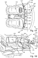
- Fig. 1A schematically illustrates an entertainment system 100 for a vehicle 102.
- Fig. 1B is a side view of the entertainment system 100 in the vehicle 102.
- the entertainment system 100 comprises a sound emitting module 104 including multiple sound emitting units 106.
- the sound emitting module 104 is adapted to be arranged such that the multiple sound emitting units 106 are distributed along the transverse extension of a windshield 108 of the vehicle 102 and to emit sound waves 107, better seen in fig. 1B , towards the windshield 108.
- the entertainment system 100 comprises a display device 110 that is arranged to cover the sound emitting module 104 as seen from the occupant seating position 112.
- the display device 110 is arranged between the sound emitting module 104 and an occupant seating position 112.
- a sound emitting unit includes components for transforming an electrical signal to a soundwave that propagates from the sound emitting unit, i.e. the sound emitting unit may be an electroacoustic transformer. Such components may include a membrane that may be caused to vibrate to thereby create soundwaves.
- a sound emitting unit may generally be a "loudspeaker".
- a transverse extension of the vehicle may be along an axis 114 that lie in a side-to-side orientation of the vehicle.
- the transverse extension indicated by the axis 114 may be substantially perpendicular to a vehicle heading direction.
- the width of the windshield is defined as the extension of the windshield along the transverse axis 114.
- the multiple sound emitting units may be arranged to emit sound waves directly towards the windshield such that the soundwaves are redirected by the windshield rearwards in the vehicle interior, i.e. in the vehicle cabin.
- That the display device is arranged between the sound emitting module 104 and an occupant seating position 112 means that the display device is arranged in an intermediate position between the position of the sound emitting module and the occupant seating position 112. This means that, as seen from the occupant seating position 112, the sound emitting module 104 may be considered hidden behind the display device 110.
- An occupant seating position may be defined by a vehicle seat. Further, as seen from the occupant seating position, may be what is visible to a person 120 situated in the vehicle seat 122. That the display device is arranged to cover the sound emitting module as seen from the occupant seating position may thus be considered that the display device is arranged in the line of sight 118 from the occupant seating position 112, to a person situated in a seated upright posture in the vehicle seat 122.
- the sound emitting module 104 may be integrated in a structure 124 adjacent to a lower portion 126 of the windshield 108.
- the lower portion 126 of the windshield is the vertically lower portion of the windshield when the windshield 108 is mounted in the vehicle, i.e. closest to the hood of the vehicle.
- the display device 110 reaches to a height that exceeds that of the highest point of the sound emitting module 104 that may be arranged adjacent to the lower windshield portion 126.
- a portion 128 of the display device 110 is adapted to reach above the plane 130 of the structure 124 where the sound emitting module 104 may be integrated. In this way may the display device 110 cover the sound emitting module 104 as seen from the occupant seating position 112.
- the structure 124 may generally be a dashboard of the vehicle.
- the sound emitting module 104 may be arranged flush with the plane 130 of the structure 124 or below the plane 130. Further, the sound emitting module 104 may be arranged to reach above the plane 130 of the structure 124 with the constraint that the display device 110 covers the sound emitting module 104 as seen from the occupant seating position 112.
- the occupant seating position is here shown in the driver's seat 122 facing the steering wheel 132. However, the occupant seating position may equally well be in the passenger front seat next to the driver's seat.
- the multiple sound emitting units 104 are distributed along substantially the entire width of the windshield 108.
- the multiple sound emitting units 104 are distributed along a large portion of the width of the windshield 108 along the transverse axis 114.
- the multiple sound emitting units 104 may be distributed along 50%, 60%, 70%, 80%, 90% of the width of the windshield 108.
- Substantially the entire width of the windshield 108 may be at least 80% of the entire width of the windshield 108.
- a larger sound emitting module advantageously provides for including a larger number of sound emitting units 106 which enables for improving the audio quality of the entertainment system 100, and for better distribution of the sound in the vehicle cabin.
- Fig. 2A schematically illustrates the entertainment system 100, and that the sound emitting module 104 is adapted to be arranged in an air vent outlet 136 arranged adjacent to the windshield 108 of the vehicle and adapted to direct an air flow towards the windshield 108, the air vent outlet 136 having a main extension along the width of the windshield 108.
- Fig. 2B is a side view of the entertainment system 100 having the sound emitting module 104 arranged in an air vent outlet 136.
- This provides for improved integration of the sound emitting module 104 in the vehicle interior.
- an an air vent mesh 306 may be arrangeable to cover the air vent outlet and the multiple sound emitting units as will be described in more detail with reference to subsequent drawings.
- the multiple sound emitting units are hidden under the same mesh as the air vent outlet, thereby reducing the number of parts and thereby also the overall cost.
- the air vent outlet 136 may extend along substantially the entire width of the windshield.
- the display device 110 is arranged adjacent to the air vent outlet 136, and in the plane of the air vent outlet 136 further from the windshield 108 than the air vent outlet 136. Further, the display device 110 is arranged in the line of sight 118 from the occupant seating position 112 to the air vent outlet.
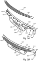
- Fig. 3A conceptually illustrates a sound emitting module 104 arranged in an air vent outlet 136.
- the sound emitting module includes a support structure 302 supporting each of the sound emitting units 106 and 304.
- the sound emitting module includes at least two different types of sound emitting units 106 and 304 having different audio characteristics. For example, a first type of sound emitting units 106 (only one is numbered) may adapted for a different frequency range of sound than a second type of sound emitting units 304 (only one is numbered).
- Example types of sound emitting units include subwoofers, woofers, midrange, tweeters.
- a sound emitting module may include more than two types of sound emitting units, such as three, or four, or five different types of sound emitting units.
- An air vent mesh 306 is arrangeable to cover the air vent outlet 136 and the multiple sound emitting units 106, 306 as is conceptually illustrated in fig 3B .
- the air vent mesh 306 includes openings 308 that allow for air and sound-waves to propagate through the mesh 306.
- the air vent outlet 136 may be a defroster air outlet for supplying an air flow for defrosting the windshield 108.
- a defroster air outlet provides a suitable location for integrating the sound emitting module 104. Firstly, the location allows for hiding the sound emitting module 104 behind the display device 110. Further the defroster air outlet 136 has an extension across the width of the windshield for providing an air flow thereto. Accordingly, the sound emitting module may therefore also be arranged along the width of the windshield.
- the air vent outlet 136 may be included in a cross-car beam 310.
- the cross-car beam 310 may be adapted for absorbing impact energy in the event of a collision. Accordingly, the cross-car beam may be adapted for causing a desired behavior of the vehicle structure in the event of a collision. For example, the cross-car beam may be adapted to bend in a predictive way in order to absorb energy in a collision. Further, the cross-car beam may be adapted to prevent a collapse of the vehicle cabin in the event of a collision.
- the cross-car beam 306 is adapted to reach from side-to-side in the vehicle.
- side-to-side means along an axis perpendicular to a vehicle heading, e.g. from left-to-right of the vehicle is considered side-to-side.
- the cross-car beam 310 further includes attachment portions 330, 331 extending from the frame structure 112 for mounting of the cross-car beam 310 to a vehicle body.
- the attachment portions 330, 331 include holes 333 for bolting or screwing the cross-car beam to the vehicle body.
- the cross-car beam is adapted to be arranged in a lateral orientation in the vehicle, i.e. along a side-to-side direction of the vehicle.
- the attachment portions 330, 331 extend downwards from a main body 314 of the cross-car beam, when the cross-car beam is arranged in a vehicle.
- the cross-car beam 306 is here shown to include a set of flanges 336.
- the flanges 336 are adapted as cooling flanges for improving the cooling of a display device attached to the main body 314, as shown in fig. 4 .
- flanges 336 increase the surface area in contact with surrounding ambient air to thereby improve the heat exchange for the component attached to the flanges with the ambient air.
- the flanges 336 are attached to a shoulder 338 of the cross-car beam 310 which includes a center valley portion 340 neighboring side shoulder portions 342 and 344. At least a portion of the flanges 336 are attached to the valley shoulder portion 340.
- the flanges 336 are generally planar, and plate shaped and arranged in parallel although this is not strictly required.
- the valley shoulder portion 340 is adapted to receive cooling air from the climate system of the vehicle, for example from a defroster air vent arranged adjacent a windshield. The air from the climate system passes in between the flanges so that heat may be exchanged between the flanges and the air.
- the sound emitting module 104 may be attached to the side shoulder portions 342 and 344 by suitable means including screws, bolts, nut and pin bolt, adhesives, clips, etc.
- Fig. 4 conceptually illustrates an entertainment system according to embodiments of the present disclosure.
- the display device 110 includes a matrix of color controllable light emitting units 402 attached to a first side of the cross-car beam 310.
- the first side is opposite to the side of the cross-car beam where the sound emitting module 104 is arranged.
- the air vent outlet 136 is included on a second side of the cross-car beam opposite the first side.
- the sound emitting module may be a soundbar.
- a soundbar includes a set of speakers having multiple characteristics, to in this way provide a complete audio solution.
- the sound emitting module comprises multiple sound emitting units adapted to be arranged such that the multiple sound emitting units are distributed along the transverse extension of a windshield of the vehicle and to emit sound towards the windshield, and covered by a display device arranged between the sound emitting module and an occupant seating position, wherein the sound emitting module is arranged behind the display device as seen from the occupant seating position.
- a display device for a vehicle entertainment system adapted to be arranged between a sound emitting module and an occupant seating position, wherein the sound emitting module is adapted to be arranged such that multiple sound emitting units of the sound emitting module are distributed along the transverse extension of a windshield of the vehicle and to emit sound towards the windshield, wherein the display device is arranged to cover the sound emitting module as seen from the occupant seating position.
- the display device 110 comprises a matrix 402 of color controllable light emitting units covered by an at least partly transparent cover.
- the display device further comprises a back-cover structure for mechanically supporting the matrix of color controllable light emitting units and to cover the side of the matrix of color controllable light emitting units opposite from the side of the transparent cover.
- the matrix of color controllable light emitting units are interleaved between the at least partly transparent cover and the back-cover structure.
- the back-cover structure may be the cross-car beam 310.
- the cross-car beam can serve as a back-cover structure for the display device.
- This insight provides for integrating entertainment systems including displays and sound emitting modules in the vehicle interior without compromising the structural integrity of the vehicle.
- the entertainment system contributes to the structural integrity since the display device includes a cross-car beam onto which the sound emitting module is attached too.
- a cross-car beam has wide extension in the cross-car direction, thereby enabling for a wide matrix of color controllable light emitting units to be installed in the cross-car beam opening for larger display devices in vehicles.
- a back cover is often provided as a plastic housing part.
- the prior art display is attached to a dedicated rack or similar structure. When the display is large, this becomes cumbersome. Therefore, the inventors propose that the display device back cover constitutes a cross-car beam, in other words, the matrix of color controllable light emitting units is attached on the cross-car beam without any additional back covers.
- the cross-car beam 310 thus includes a main body 314 that is adapted to cover the back side 408 of the matrix 402 of color controllable light emitting units such that the matrix 402 of color controllable light emitting units are protected at the back side 408.
- the sound emitting module 104 is arranged on the opposite side of the cross-car beam, i.e. covered by the display device.
- the back side is 408 is opposite the front side 410.
- the at least partly transparent cover 404 is a see-through cover arranged to protect the front side 410 of the matrix 402 of color controllable light emitting units from mechanical damage.
- the at least partly transparent cover 404 may include optical filters.
- the at least partly transparent cover 404 is adapted such that the matrix 402 of color controllable light emitting units can transmit visible light through the at least partly transparent cover 404 so that the visible light is emitted from the front side 410 towards a user facing the front side 410.
- the at least partly transparent cover 404 may for example be made from glass. The emitted light is transmitted through the material, e.g. the glass, of the at least partly transparent cover 404.
- the matrix 402 of color controllable light emitting units may be directly attached to the cross-car beam 310. In other words, the matrix 402 of color controllable light emitting units may abut against the cross-car beam 310.
- the color controllable light emitting units may include pixel elements of various types adapted to emit color controllable light.
- the matrix 402 of color controllable light emitting units may further include e.g. optical filters such as polarizing filters, glass substrates, reflective surfaces, or other components necessary for the structure and function of a display.
- the color controllable light emitting units may be pixel elements of types including liquid crystal display pixels elements, light emitting diode pixel elements, organic light emitting diode pixel elements.
- the matrix 402 of color controllable light emitting units may be a display including liquid crystal display pixels elements.
- the matrix 402 of color controllable light emitting units may be a display including light emitting diode pixel elements.
- the matrix 402 of color controllable light emitting units may be a display including organic light emitting diode pixel elements.
- the cross-car beam 310 may be made by extrusion or molding and made be made from magnesium for reducing the weight of the beam 310.
- the entertainment system is controlled by at least one control unit which may be configured to receive input commands from users and control the sound emitting module and the display device to emit audio signals and display images, videos, or other data and information as requested.
- control unit which may be configured to receive input commands from users and control the sound emitting module and the display device to emit audio signals and display images, videos, or other data and information as requested.
- the entertainment system may further include wireless communication means for receiving and sending data and from/to a server, or generally the “Cloud”, from/to handheld electronic devices such as mobile phones, tablets, laptops, etc., or from other vehicles or infrastructure i.e. V2V or V2X.
- wireless communication means may include any of Wifi, 3G, 4G, 5G, etc., Bluetooth, IR-communication.
- a control unit may include a microprocessor, microcontroller, programmable digital signal processor or another programmable device, as well as be embedded into the vehicle/power train control logic/hardware.
- the control unit may also, or instead, include an application-specific integrated circuit, a programmable gate array or programmable array logic, a programmable logic device, or a digital signal processor.
- the processor may further include computer executable code that controls operation of the programmable device.
- the control unit may comprise modules in either hardware or software, or partially in hardware or software and communicate using known transmission buses such as CAN-bus and/or wireless communication capabilities.
Landscapes
- Engineering & Computer Science (AREA)
- Physics & Mathematics (AREA)
- Signal Processing (AREA)
- Health & Medical Sciences (AREA)
- Otolaryngology (AREA)
- Acoustics & Sound (AREA)
- Mechanical Engineering (AREA)
- Transportation (AREA)
- Combustion & Propulsion (AREA)
- Chemical & Material Sciences (AREA)
- Computer Hardware Design (AREA)
- General Physics & Mathematics (AREA)
- Theoretical Computer Science (AREA)
- General Health & Medical Sciences (AREA)
- Fittings On The Vehicle Exterior For Carrying Loads, And Devices For Holding Or Mounting Articles (AREA)
Abstract
Description
- The present disclosure generally relates to an entertainment system for a vehicle. The present disclosure further relates to a sound emitting module for a vehicle entertainment system, to a display device for a vehicle entertainment system, and to a vehicle comprising an entertainment system.
- Vehicle entertainment systems are becoming more advanced and at least in premium vehicles provide for high quality display and audio systems, and often with the ability to connect to cloud services for accessing e.g. music. The vehicle manufacturers spend much effort in integrating the entertainment systems in the vehicle in visually appealing ways. At the same time, the integration of the entertainment systems should provide a user-friendly control of the entertainment systems to enhance the user experience.
- The overall impression of the vehicle cabin with the more advanced entertainment systems appears to be approaching a "living room experience". However, there is still room for improving the entertainment systems in this regard. For example, components such as more advanced displays and audio systems may be areas of improvement. Further, ways of integrating for example displays and audio systems is another area where improvements are conceivable.
- The disclosed subject matter generally relates to an entertainment system for a vehicle which provide for improved integration of at least a sound emitting module in the vehicle.
- In prior art entertainment systems in vehicles, the speakers are distributed over a large portion of the vehicle interior in an attempt to provide satisfactory sound quality. There may be speakers arranged in e.g. doors, on the instrument panel, and in the ceiling.
- However, through extensive testing the inventors realized that a large portion of sound emitting units can instead be placed such that the multiple sound emitting units are distributed along the transverse extension of a windshield of the vehicle and to emit sound towards the windshield while still providing at least acceptable or even improved sound quality sound quality for the occupants of the vehicle. This provides for a more integrated system in which the sound emitting units can be hidden for the occupants of the vehicle.
- The disclosed entertainment system further provides the advantage of integrating a more advanced sound system in the form of a sound emitting module including multiple sound emitting units. The multiple sound emitting units are arrangeable between a display device and a windshield. In this way, the multiple sound emitting units are arranged behind the display device as seen from an occupant seating position. Thus, the multiple sound emitting units are not visible for the occupants seated in the vehicle. Further, the multiple sound emitting units are integrated in the vehicle interior without obstructing design features or other functional features, thereby making more space available for such other features. In addition, despite the suggested location of the sound emitting module, the sound quality in the vehicle cabin may be improved.
- In a first aspect, the present disclosure provides an entertainment system for a vehicle, the system comprising: a sound emitting module including multiple sound emitting units, wherein the sound emitting module is adapted to be arranged such that the multiple sound emitting units are distributed along the transverse extension of a windshield of the vehicle and to emit sound towards the windshield, and a display device arranged to cover the sound emitting module as seen from the occupant seating position.
- The disclosed entertainment system provides for improved integration of a sound emitting module which can provide improved sound quality in the vehicle cabin. In particular, the sound emitting module may be provided as a soundbar often used in advanced home audio system.
- In one embodiment, the sound emitting module is adapted to be arranged in an air vent outlet arranged adjacent to the windshield of the vehicle and adapted to direct an air flow towards the windshield, the air vent outlet having a main extension along the width of the windshield. This provides for even further improved integration of the sound emitting module in the vehicle interior. For example, an an air vent mesh may be arrangeable to cover the air vent outlet and the multiple sound emitting units. Thus, the multiple sound emitting units are hidden also under the same mesh as the air vent outlet, thereby reducing the number of parts and also the overall cost.
- Further features of, and advantages with, the embodiments of the present disclosure will become apparent when studying the appended claims and the following description. The skilled person realize that different features of the present disclosure may be combined to create embodiments other than those described in the following, without departing from the scope of the present disclosure.
- These and other aspects of the entertainment system will now be described in more detail, with reference to the appended drawings showing example embodiments of the present disclosure, wherein:
-
FIG. 1A conceptually illustrates an entertainment system for a vehicle according to embodiments of the present disclosure; -
FIG. 1B is a side view of the entertainment system shown infig. 1A ; -
FIG. 2A conceptually illustrates an entertainment system for a vehicle according to embodiments of the present disclosure; -
FIG. 2B is a side view of the entertainment system shown infig. 2A ; -
FIG. 3A is a conceptual illustration of a sound emitting module mounted in an air vent outlet included in a cross-car beam according to embodiments of the present disclosure; -
FIG. 3B is a conceptual illustration of a sound emitting module mounted in an air vent outlet included in a cross-car beam according to embodiments of the present disclosure; -
FIG. 4 conceptually illustrates an entertainment system according to embodiments of the present disclosure; - In the present detailed description, various embodiments of an entertainment system according to the present disclosure are described. However, the entertainment system may be embodied in many different forms and should not be construed as limited to the embodiments set forth herein; rather, these embodiments are provided for thoroughness and completeness, and to fully convey the scope of the present disclosure to the skilled person. Like reference characters refer to like elements throughout.
-
Fig. 1A schematically illustrates anentertainment system 100 for avehicle 102.Fig. 1B is a side view of theentertainment system 100 in thevehicle 102. Theentertainment system 100 comprises asound emitting module 104 including multiplesound emitting units 106. Thesound emitting module 104 is adapted to be arranged such that the multiplesound emitting units 106 are distributed along the transverse extension of awindshield 108 of thevehicle 102 and to emitsound waves 107, better seen infig. 1B , towards thewindshield 108. Theentertainment system 100 comprises adisplay device 110 that is arranged to cover thesound emitting module 104 as seen from theoccupant seating position 112. - In this example embodiment, the
display device 110 is arranged between thesound emitting module 104 and anoccupant seating position 112. - A sound emitting unit includes components for transforming an electrical signal to a soundwave that propagates from the sound emitting unit, i.e. the sound emitting unit may be an electroacoustic transformer. Such components may include a membrane that may be caused to vibrate to thereby create soundwaves. A sound emitting unit may generally be a "loudspeaker".
- A transverse extension of the vehicle may be along an
axis 114 that lie in a side-to-side orientation of the vehicle. In other words, the transverse extension indicated by theaxis 114 may be substantially perpendicular to a vehicle heading direction. The width of the windshield is defined as the extension of the windshield along thetransverse axis 114. - That the sound emitting units are arranged to emit
soundwaves 107 towards the windshield means that the soundwaves leaving the sound emitting units propagates in a direction that intercepts with thewindshield 108. Thus, when thesoundwaves 107 has propagated for a time duration, they will eventually bounce off theinner side 116 of thewindshield 108, facing the vehicle interior, and propagate rearwards in the vehicle interior. Thus, the multiple sound emitting units may be arranged to emit sound waves directly towards the windshield such that the soundwaves are redirected by the windshield rearwards in the vehicle interior, i.e. in the vehicle cabin. - That the display device is arranged between the
sound emitting module 104 and anoccupant seating position 112 means that the display device is arranged in an intermediate position between the position of the sound emitting module and theoccupant seating position 112. This means that, as seen from theoccupant seating position 112, thesound emitting module 104 may be considered hidden behind thedisplay device 110. - An occupant seating position may be defined by a vehicle seat. Further, as seen from the occupant seating position, may be what is visible to a
person 120 situated in thevehicle seat 122. That the display device is arranged to cover the sound emitting module as seen from the occupant seating position may thus be considered that the display device is arranged in the line ofsight 118 from theoccupant seating position 112, to a person situated in a seated upright posture in thevehicle seat 122. - The
sound emitting module 104 may be integrated in astructure 124 adjacent to alower portion 126 of thewindshield 108. Thelower portion 126 of the windshield is the vertically lower portion of the windshield when thewindshield 108 is mounted in the vehicle, i.e. closest to the hood of the vehicle. Thedisplay device 110 reaches to a height that exceeds that of the highest point of thesound emitting module 104 that may be arranged adjacent to thelower windshield portion 126. For example, aportion 128 of thedisplay device 110 is adapted to reach above theplane 130 of thestructure 124 where thesound emitting module 104 may be integrated. In this way may thedisplay device 110 cover thesound emitting module 104 as seen from theoccupant seating position 112. Thestructure 124 may generally be a dashboard of the vehicle. Thesound emitting module 104 may be arranged flush with theplane 130 of thestructure 124 or below theplane 130. Further, thesound emitting module 104 may be arranged to reach above theplane 130 of thestructure 124 with the constraint that thedisplay device 110 covers thesound emitting module 104 as seen from theoccupant seating position 112. - The occupant seating position is here shown in the driver's
seat 122 facing thesteering wheel 132. However, the occupant seating position may equally well be in the passenger front seat next to the driver's seat. - In embodiments, the multiple
sound emitting units 104 are distributed along substantially the entire width of thewindshield 108. InFig. 1A the multiplesound emitting units 104 are distributed along a large portion of the width of thewindshield 108 along thetransverse axis 114. For example, the multiplesound emitting units 104 may be distributed along 50%, 60%, 70%, 80%, 90% of the width of thewindshield 108. Substantially the entire width of thewindshield 108 may be at least 80% of the entire width of thewindshield 108. A larger sound emitting module advantageously provides for including a larger number ofsound emitting units 106 which enables for improving the audio quality of theentertainment system 100, and for better distribution of the sound in the vehicle cabin. -
Fig. 2A schematically illustrates theentertainment system 100, and that thesound emitting module 104 is adapted to be arranged in anair vent outlet 136 arranged adjacent to thewindshield 108 of the vehicle and adapted to direct an air flow towards thewindshield 108, theair vent outlet 136 having a main extension along the width of thewindshield 108.Fig. 2B is a side view of theentertainment system 100 having thesound emitting module 104 arranged in anair vent outlet 136. This provides for improved integration of thesound emitting module 104 in the vehicle interior. For example, an anair vent mesh 306 may be arrangeable to cover the air vent outlet and the multiple sound emitting units as will be described in more detail with reference to subsequent drawings. Thus, the multiple sound emitting units are hidden under the same mesh as the air vent outlet, thereby reducing the number of parts and thereby also the overall cost. - The
air vent outlet 136 may extend along substantially the entire width of the windshield. - Turning now to
fig. 2B , thedisplay device 110 is arranged adjacent to theair vent outlet 136, and in the plane of theair vent outlet 136 further from thewindshield 108 than theair vent outlet 136. Further, thedisplay device 110 is arranged in the line ofsight 118 from theoccupant seating position 112 to the air vent outlet. -
Fig. 3A conceptually illustrates asound emitting module 104 arranged in anair vent outlet 136. The sound emitting module includes asupport structure 302 supporting each of thesound emitting units sound emitting units - An
air vent mesh 306 is arrangeable to cover theair vent outlet 136 and the multiplesound emitting units fig 3B . Theair vent mesh 306 includesopenings 308 that allow for air and sound-waves to propagate through themesh 306. - The
air vent outlet 136 may be a defroster air outlet for supplying an air flow for defrosting thewindshield 108. A defroster air outlet provides a suitable location for integrating thesound emitting module 104. Firstly, the location allows for hiding thesound emitting module 104 behind thedisplay device 110. Further thedefroster air outlet 136 has an extension across the width of the windshield for providing an air flow thereto. Accordingly, the sound emitting module may therefore also be arranged along the width of the windshield. - Tuning again to
fig. 3A , theair vent outlet 136 may be included in across-car beam 310. Thecross-car beam 310 may be adapted for absorbing impact energy in the event of a collision. Accordingly, the cross-car beam may be adapted for causing a desired behavior of the vehicle structure in the event of a collision. For example, the cross-car beam may be adapted to bend in a predictive way in order to absorb energy in a collision. Further, the cross-car beam may be adapted to prevent a collapse of the vehicle cabin in the event of a collision. - The
cross-car beam 306 is adapted to reach from side-to-side in the vehicle. Again, the term side-to-side means along an axis perpendicular to a vehicle heading, e.g. from left-to-right of the vehicle is considered side-to-side. - The
cross-car beam 310 further includesattachment portions frame structure 112 for mounting of thecross-car beam 310 to a vehicle body. In this example embodiment, theattachment portions holes 333 for bolting or screwing the cross-car beam to the vehicle body. The cross-car beam is adapted to be arranged in a lateral orientation in the vehicle, i.e. along a side-to-side direction of the vehicle. Theattachment portions main body 314 of the cross-car beam, when the cross-car beam is arranged in a vehicle. - The
cross-car beam 306 is here shown to include a set offlanges 336. Theflanges 336 are adapted as cooling flanges for improving the cooling of a display device attached to themain body 314, as shown infig. 4 . Generally,flanges 336 increase the surface area in contact with surrounding ambient air to thereby improve the heat exchange for the component attached to the flanges with the ambient air. Theflanges 336 are attached to ashoulder 338 of thecross-car beam 310 which includes acenter valley portion 340 neighboringside shoulder portions 342 and 344. At least a portion of theflanges 336 are attached to thevalley shoulder portion 340. Theflanges 336 are generally planar, and plate shaped and arranged in parallel although this is not strictly required. Thevalley shoulder portion 340 is adapted to receive cooling air from the climate system of the vehicle, for example from a defroster air vent arranged adjacent a windshield. The air from the climate system passes in between the flanges so that heat may be exchanged between the flanges and the air. - The
sound emitting module 104 may be attached to theside shoulder portions 342 and 344 by suitable means including screws, bolts, nut and pin bolt, adhesives, clips, etc. -
Fig. 4 conceptually illustrates an entertainment system according to embodiments of the present disclosure. Here, thedisplay device 110 includes a matrix of color controllablelight emitting units 402 attached to a first side of thecross-car beam 310. The first side is opposite to the side of the cross-car beam where thesound emitting module 104 is arranged. Further, theair vent outlet 136 is included on a second side of the cross-car beam opposite the first side. - The sound emitting module may be a soundbar. A soundbar includes a set of speakers having multiple characteristics, to in this way provide a complete audio solution.
- There is further provided a vehicle comprising the entertainment system according to embodiments of the present disclosure.
- There is further provided a sound emitting module for a vehicle entertainment system, the sound emitting module comprises multiple sound emitting units adapted to be arranged such that the multiple sound emitting units are distributed along the transverse extension of a windshield of the vehicle and to emit sound towards the windshield, and covered by a display device arranged between the sound emitting module and an occupant seating position, wherein the sound emitting module is arranged behind the display device as seen from the occupant seating position.
- There is further provided a display device for a vehicle entertainment system, adapted to be arranged between a sound emitting module and an occupant seating position, wherein the sound emitting module is adapted to be arranged such that multiple sound emitting units of the sound emitting module are distributed along the transverse extension of a windshield of the vehicle and to emit sound towards the windshield, wherein the display device is arranged to cover the sound emitting module as seen from the occupant seating position.
- The
display device 110 comprises amatrix 402 of color controllable light emitting units covered by an at least partly transparent cover. The display device further comprises a back-cover structure for mechanically supporting the matrix of color controllable light emitting units and to cover the side of the matrix of color controllable light emitting units opposite from the side of the transparent cover. The matrix of color controllable light emitting units are interleaved between the at least partly transparent cover and the back-cover structure. The back-cover structure may be thecross-car beam 310. - Accordingly, the inventors further realized that the cross-car beam can serve as a back-cover structure for the display device. This insight provides for integrating entertainment systems including displays and sound emitting modules in the vehicle interior without compromising the structural integrity of the vehicle. In fact, the entertainment system contributes to the structural integrity since the display device includes a cross-car beam onto which the sound emitting module is attached too. Furthermore, a cross-car beam has wide extension in the cross-car direction, thereby enabling for a wide matrix of color controllable light emitting units to be installed in the cross-car beam opening for larger display devices in vehicles.
- In prior art displays, a back cover is often provided as a plastic housing part. The prior art display is attached to a dedicated rack or similar structure. When the display is large, this becomes cumbersome. Therefore, the inventors propose that the display device back cover constitutes a cross-car beam, in other words, the matrix of color controllable light emitting units is attached on the cross-car beam without any additional back covers.
- Turning again to
fig. 4 , thecross-car beam 310 thus includes amain body 314 that is adapted to cover theback side 408 of thematrix 402 of color controllable light emitting units such that thematrix 402 of color controllable light emitting units are protected at theback side 408. Thesound emitting module 104 is arranged on the opposite side of the cross-car beam, i.e. covered by the display device. The back side is 408 is opposite thefront side 410. - The at least partly
transparent cover 404 is a see-through cover arranged to protect thefront side 410 of thematrix 402 of color controllable light emitting units from mechanical damage. The at least partlytransparent cover 404 may include optical filters. However, the at least partlytransparent cover 404 is adapted such that thematrix 402 of color controllable light emitting units can transmit visible light through the at least partlytransparent cover 404 so that the visible light is emitted from thefront side 410 towards a user facing thefront side 410. The at least partlytransparent cover 404 may for example be made from glass. The emitted light is transmitted through the material, e.g. the glass, of the at least partlytransparent cover 404. - The
matrix 402 of color controllable light emitting units may be directly attached to thecross-car beam 310. In other words, thematrix 402 of color controllable light emitting units may abut against thecross-car beam 310. - The color controllable light emitting units may include pixel elements of various types adapted to emit color controllable light. The
matrix 402 of color controllable light emitting units may further include e.g. optical filters such as polarizing filters, glass substrates, reflective surfaces, or other components necessary for the structure and function of a display. For example, the color controllable light emitting units may be pixel elements of types including liquid crystal display pixels elements, light emitting diode pixel elements, organic light emitting diode pixel elements. Thus, thematrix 402 of color controllable light emitting units may be a display including liquid crystal display pixels elements. In other possible implementations, thematrix 402 of color controllable light emitting units may be a display including light emitting diode pixel elements. In other possible implementations, thematrix 402 of color controllable light emitting units may be a display including organic light emitting diode pixel elements. - The
cross-car beam 310 may be made by extrusion or molding and made be made from magnesium for reducing the weight of thebeam 310. - The entertainment system according to embodiments of the present disclosure is controlled by at least one control unit which may be configured to receive input commands from users and control the sound emitting module and the display device to emit audio signals and display images, videos, or other data and information as requested. The specific details regarding control and operation of a vehicle entertainment systems including displays and speakers is considered known to the skilled person and will not be described in detail herein.
- The entertainment system may further include wireless communication means for receiving and sending data and from/to a server, or generally the "Cloud", from/to handheld electronic devices such as mobile phones, tablets, laptops, etc., or from other vehicles or infrastructure i.e. V2V or V2X. Such wireless communication means may include any of Wifi, 3G, 4G, 5G, etc., Bluetooth, IR-communication.
- A control unit may include a microprocessor, microcontroller, programmable digital signal processor or another programmable device, as well as be embedded into the vehicle/power train control logic/hardware. The control unit may also, or instead, include an application-specific integrated circuit, a programmable gate array or programmable array logic, a programmable logic device, or a digital signal processor. Where the control unit includes a programmable device such as the microprocessor, microcontroller or programmable digital signal processor mentioned above, the processor may further include computer executable code that controls operation of the programmable device. The control unit may comprise modules in either hardware or software, or partially in hardware or software and communicate using known transmission buses such as CAN-bus and/or wireless communication capabilities.
- The person skilled in the art realizes that the present invention by no means is limited to the preferred embodiments described above. On the contrary, many modifications and variations are possible within the scope of the appended claims.
- In the claims, the word "comprising" does not exclude other elements or steps, and the indefinite article "a" or "an" does not exclude a plurality. A single processor or other control unit may fulfil the functions of several items recited in the claims. The mere fact that certain measures are recited in mutually different dependent claims does not indicate that a combination of these measured cannot be used to advantage. Any reference signs in the claims should not be construed as limiting the scope.
- Various examples have been described. These and other examples are within the scope of the following claims.
Claims (15)
- An entertainment system for a vehicle, the entertainment system comprising:a sound emitting module including multiple sound emitting units, wherein the sound emitting module is adapted to be arranged such that the multiple sound emitting units are distributed along the transverse extension of a windshield of the vehicle and to emit sound towards the windshield, anda display device arranged to cover the sound emitting module as seen from the occupant seating position.
- The entertainment system according to claim 1, wherein the multiple sound emitting units are distributed along substantially the entire width of the windshield.
- The entertainment system according to any one of claims 1 and 2, wherein the multiple sound emitting units are arranged to emit sound waves directly towards the windshield such that the soundwaves are redirected by the windshield rearwards in the vehicle cabin.
- The entertainment system according to any one of the preceding claims, wherein the sound emitting module includes a support structure supporting each of the sound emitting units.
- The entertainment system according to any one of the preceding claims, wherein the sound emitting module is adapted to be arranged in an air vent outlet arranged adjacent to the windshield of the vehicle and adapted to direct an air flow towards the windshield, the air vent outlet having a main extension along the width of the windshield.
- The entertainment system according to claim 5, comprising an air vent mesh arrangeable to cover the air vent outlet and the multiple sound emitting units.
- The entertainment system according to any one of claims 5 or 6, wherein the display device is arranged adjacent to the air vent, further from the windshield in the plane of the air vent than the air vent.
- The entertainment system according to any one of the preceding claims, wherein the display device is arranged in the line of sight from the occupant seating position to the air vent outlet.
- The entertainment system according to any one of the preceding claims, wherein the display device includes a matrix of color controllable light emitting units is attachable to a first side of a cross-car beam.
- The entertainment system according to claim 9, wherein the air vent outlet is included on a second side of the cross-car beam opposite the first side.
- The entertainment system according to any one of the preceding claims, wherein the sound emitting module includes at least two different types of sound emitting units having different audio characteristics.
- The entertainment system according to any one of the preceding claims, wherein the sound emitting module is a soundbar.
- The entertainment system according to any one of claims 5 to 11, wherein the air vent outlet is a defroster air outlet for supplying an air flow for defrosting the windshield.
- A vehicle comprising the entertainment system according to any one of the preceding claims.
- A sound emitting module for a vehicle entertainment system, the sound emitting module comprises multiple sound emitting units adapted to be arranged such that the multiple sound emitting units are distributed along the transverse extension of a windshield of the vehicle and to emit sound towards the windshield, and covered by a display device arranged between the sound emitting module and an occupant seating position, wherein the sound emitting module is arranged behind the display device as seen from the occupant seating position.
Priority Applications (2)
| Application Number | Priority Date | Filing Date | Title |
|---|---|---|---|
| EP19208035.6A EP3819157B1 (en) | 2019-11-08 | 2019-11-08 | An entertainment system for a vehicle including a sound emitting module |
| US17/079,697 US11622191B2 (en) | 2019-11-08 | 2020-10-26 | Entertainment system for a vehicle including a sound emitting module |
Applications Claiming Priority (1)
| Application Number | Priority Date | Filing Date | Title |
|---|---|---|---|
| EP19208035.6A EP3819157B1 (en) | 2019-11-08 | 2019-11-08 | An entertainment system for a vehicle including a sound emitting module |
Publications (2)
| Publication Number | Publication Date |
|---|---|
| EP3819157A1 true EP3819157A1 (en) | 2021-05-12 |
| EP3819157B1 EP3819157B1 (en) | 2023-04-05 |
Family
ID=68501453
Family Applications (1)
| Application Number | Title | Priority Date | Filing Date |
|---|---|---|---|
| EP19208035.6A Active EP3819157B1 (en) | 2019-11-08 | 2019-11-08 | An entertainment system for a vehicle including a sound emitting module |
Country Status (2)
| Country | Link |
|---|---|
| US (1) | US11622191B2 (en) |
| EP (1) | EP3819157B1 (en) |
Families Citing this family (1)
| Publication number | Priority date | Publication date | Assignee | Title |
|---|---|---|---|---|
| EP3819157B1 (en) * | 2019-11-08 | 2023-04-05 | Volvo Car Corporation | An entertainment system for a vehicle including a sound emitting module |
Citations (7)
| Publication number | Priority date | Publication date | Assignee | Title |
|---|---|---|---|---|
| US5699057A (en) * | 1995-06-16 | 1997-12-16 | Fuji Jukogyo Kabushiki Kaisha | Warning system for vehicle |
| US5870484A (en) * | 1995-09-05 | 1999-02-09 | Greenberger; Hal | Loudspeaker array with signal dependent radiation pattern |
| EP1228916A2 (en) * | 2001-01-26 | 2002-08-07 | Volkswagen Aktiengesellschaft | Dashboard for a vehicle, in particular an automotive vehicle |
| WO2003001885A2 (en) * | 2001-06-26 | 2003-01-09 | Harman International Industries, Incorporated | Multimedia and entertainment system for an automobile |
| US20160042664A1 (en) * | 2014-08-11 | 2016-02-11 | Toyota Motor Engineering & Manufacturing North America, Inc. | Electronics demonstration and tutorial mode system |
| US20190084370A1 (en) * | 2017-09-15 | 2019-03-21 | GM Global Technology Operations LLC | Vascular structures and methods for thermal control |
| US10448180B1 (en) * | 2018-11-01 | 2019-10-15 | Toyota Motor Engineering & Manufacturing North America, Inc. | Systems and methods for vehicle external audio volume indication and control of the same |
Family Cites Families (24)
| Publication number | Priority date | Publication date | Assignee | Title |
|---|---|---|---|---|
| US5754664A (en) * | 1993-09-09 | 1998-05-19 | Prince Corporation | Vehicle audio system |
| DE19807259B4 (en) * | 1998-02-20 | 2007-09-13 | Volkswagen Ag | Ventilation system with defroster nozzle |
| US6304173B2 (en) * | 1999-01-29 | 2001-10-16 | Lear Automotive Dearborn Inc | Rear view and multi-media system for vehicles |
| US6980092B2 (en) * | 2000-04-06 | 2005-12-27 | Gentex Corporation | Vehicle rearview mirror assembly incorporating a communication system |
| US6614913B1 (en) * | 2000-06-22 | 2003-09-02 | Stuart Allen | Vehicle speaker pod |
| US7457425B2 (en) * | 2001-02-09 | 2008-11-25 | Thx Ltd. | Vehicle sound system |
| US20030227375A1 (en) * | 2002-06-07 | 2003-12-11 | Peter Yong | Automotive courtesy display |
| US7561706B2 (en) * | 2004-05-04 | 2009-07-14 | Bose Corporation | Reproducing center channel information in a vehicle multichannel audio system |
| US8457324B2 (en) * | 2005-08-16 | 2013-06-04 | Honeywell International Inc. | Directional speaker system |
| US8090116B2 (en) * | 2005-11-18 | 2012-01-03 | Holmi Douglas J | Vehicle directional electroacoustical transducing |
| US8170265B2 (en) * | 2007-06-27 | 2012-05-01 | Continental Automotive Systems Us, Inc. | Front facing electronic slave speaker |
| US8649533B2 (en) * | 2009-10-02 | 2014-02-11 | Ford Global Technologies, Llc | Emotive advisory system acoustic environment |
| DE102010009490A1 (en) * | 2010-02-26 | 2011-09-01 | Bayerische Motoren Werke Aktiengesellschaft | Motor vehicle has dashboard with control unit, which is inclined against horizontal vehicle level, where support for hand is arranged underneath control unit |
| EP2816824B1 (en) * | 2013-05-24 | 2020-07-01 | Harman Becker Automotive Systems GmbH | Sound system for establishing a sound zone |
| US10640046B1 (en) * | 2013-09-24 | 2020-05-05 | Rosco, Inc. | Convex rearview mirror and monitor with reversible back/socket mount |
| US9376002B2 (en) * | 2013-11-04 | 2016-06-28 | Omix-Ada, Inc. | Combination roof rack and removable soft top |
| JP2016022843A (en) * | 2014-07-22 | 2016-02-08 | ダイキョーニシカワ株式会社 | Duct with speaker |
| KR101687825B1 (en) * | 2015-05-18 | 2016-12-20 | 현대자동차주식회사 | Vehicle and method of controlling the same |
| US9813813B2 (en) * | 2015-08-31 | 2017-11-07 | Harman International Industries, Incorporated | Customization of a vehicle audio system |
| JP2017144800A (en) * | 2016-02-15 | 2017-08-24 | トヨタ車体株式会社 | Defroster duct |
| CN205647919U (en) * | 2016-05-09 | 2016-10-12 | 嘉兴市晶奥电子有限公司 | Automobile -used soundbar audio amplifier |
| US10782776B2 (en) * | 2017-09-28 | 2020-09-22 | Nissan North America, Inc. | Vehicle display configuration system and method |
| US10650798B2 (en) * | 2018-03-27 | 2020-05-12 | Sony Corporation | Electronic device, method and computer program for active noise control inside a vehicle |
| EP3819157B1 (en) * | 2019-11-08 | 2023-04-05 | Volvo Car Corporation | An entertainment system for a vehicle including a sound emitting module |
-
2019
- 2019-11-08 EP EP19208035.6A patent/EP3819157B1/en active Active
-
2020
- 2020-10-26 US US17/079,697 patent/US11622191B2/en active Active
Patent Citations (7)
| Publication number | Priority date | Publication date | Assignee | Title |
|---|---|---|---|---|
| US5699057A (en) * | 1995-06-16 | 1997-12-16 | Fuji Jukogyo Kabushiki Kaisha | Warning system for vehicle |
| US5870484A (en) * | 1995-09-05 | 1999-02-09 | Greenberger; Hal | Loudspeaker array with signal dependent radiation pattern |
| EP1228916A2 (en) * | 2001-01-26 | 2002-08-07 | Volkswagen Aktiengesellschaft | Dashboard for a vehicle, in particular an automotive vehicle |
| WO2003001885A2 (en) * | 2001-06-26 | 2003-01-09 | Harman International Industries, Incorporated | Multimedia and entertainment system for an automobile |
| US20160042664A1 (en) * | 2014-08-11 | 2016-02-11 | Toyota Motor Engineering & Manufacturing North America, Inc. | Electronics demonstration and tutorial mode system |
| US20190084370A1 (en) * | 2017-09-15 | 2019-03-21 | GM Global Technology Operations LLC | Vascular structures and methods for thermal control |
| US10448180B1 (en) * | 2018-11-01 | 2019-10-15 | Toyota Motor Engineering & Manufacturing North America, Inc. | Systems and methods for vehicle external audio volume indication and control of the same |
Also Published As
| Publication number | Publication date |
|---|---|
| EP3819157B1 (en) | 2023-04-05 |
| US11622191B2 (en) | 2023-04-04 |
| US20210144470A1 (en) | 2021-05-13 |
Similar Documents
| Publication | Publication Date | Title |
|---|---|---|
| EP3018560B1 (en) | Integrated overhead console assembly for vehicle | |
| JP5816811B2 (en) | Speaker system, electronic device using the same, and mobile device | |
| US20040237111A1 (en) | Multimedia and entertainment system for an automobile | |
| US20040109575A1 (en) | Vehicle audio system with directional sound and reflected audio imaging for creating a personal sound stage | |
| CN103444202B (en) | Loud speaker, the electronic equipment employing this loud speaker and mobile body device | |
| CN112172706B (en) | Motor vehicle, armrest box and vehicle-mounted bass module | |
| US11622191B2 (en) | Entertainment system for a vehicle including a sound emitting module | |
| US10827257B2 (en) | In-vehicle audio system | |
| CN101648547A (en) | Automotive entertainment system | |
| US11265634B1 (en) | Articulated vehicle speaker system | |
| CN214481217U (en) | An intelligent cockpit system and vehicle | |
| US20130259258A1 (en) | Vehicle Loudspeaker Module | |
| CN219115359U (en) | Vehicle-mounted sound system and vehicle | |
| CN114556967A (en) | Side-firing headrest speaker with omnidirectional lens | |
| EP3819155B1 (en) | Display device for a vehicle interior including a cross car beam | |
| JP3164802U (en) | Car rearview mirror | |
| CN214396427U (en) | Center console assembly with loudspeaking structure | |
| JP2005086604A (en) | Speaker mounting structure and meter integrated speaker unit | |
| JP2001270391A (en) | In-car audio-visual equipment | |
| US20240430600A1 (en) | Audio system arranged in a listening environment | |
| CN103625364B (en) | Read out instrument | |
| RU2417411C2 (en) | Portable adapter and software for use with heads-up display unit | |
| JP2021022855A (en) | Antenna fitting structure | |
| CN222408116U (en) | Vehicle-mounted transparent display screen partition | |
| JP2014091433A (en) | Steering wheel |
Legal Events
| Date | Code | Title | Description |
|---|---|---|---|
| PUAI | Public reference made under article 153(3) epc to a published international application that has entered the european phase |
Free format text: ORIGINAL CODE: 0009012 |
|
| STAA | Information on the status of an ep patent application or granted ep patent |
Free format text: STATUS: THE APPLICATION HAS BEEN PUBLISHED |
|
| AK | Designated contracting states |
Kind code of ref document: A1 Designated state(s): AL AT BE BG CH CY CZ DE DK EE ES FI FR GB GR HR HU IE IS IT LI LT LU LV MC MK MT NL NO PL PT RO RS SE SI SK SM TR |
|
| STAA | Information on the status of an ep patent application or granted ep patent |
Free format text: STATUS: REQUEST FOR EXAMINATION WAS MADE |
|
| 17P | Request for examination filed |
Effective date: 20211112 |
|
| RBV | Designated contracting states (corrected) |
Designated state(s): AL AT BE BG CH CY CZ DE DK EE ES FI FR GB GR HR HU IE IS IT LI LT LU LV MC MK MT NL NO PL PT RO RS SE SI SK SM TR |
|
| STAA | Information on the status of an ep patent application or granted ep patent |
Free format text: STATUS: EXAMINATION IS IN PROGRESS |
|
| 17Q | First examination report despatched |
Effective date: 20220311 |
|
| GRAP | Despatch of communication of intention to grant a patent |
Free format text: ORIGINAL CODE: EPIDOSNIGR1 |
|
| STAA | Information on the status of an ep patent application or granted ep patent |
Free format text: STATUS: GRANT OF PATENT IS INTENDED |
|
| INTG | Intention to grant announced |
Effective date: 20221114 |
|
| GRAS | Grant fee paid |
Free format text: ORIGINAL CODE: EPIDOSNIGR3 |
|
| GRAA | (expected) grant |
Free format text: ORIGINAL CODE: 0009210 |
|
| STAA | Information on the status of an ep patent application or granted ep patent |
Free format text: STATUS: THE PATENT HAS BEEN GRANTED |
|
| AK | Designated contracting states |
Kind code of ref document: B1 Designated state(s): AL AT BE BG CH CY CZ DE DK EE ES FI FR GB GR HR HU IE IS IT LI LT LU LV MC MK MT NL NO PL PT RO RS SE SI SK SM TR |
|
| REG | Reference to a national code |
Ref country code: GB Ref legal event code: FG4D |
|
| REG | Reference to a national code |
Ref country code: CH Ref legal event code: EP |
|
| REG | Reference to a national code |
Ref country code: AT Ref legal event code: REF Ref document number: 1557978 Country of ref document: AT Kind code of ref document: T Effective date: 20230415 |
|
| REG | Reference to a national code |
Ref country code: DE Ref legal event code: R096 Ref document number: 602019027135 Country of ref document: DE |
|
| REG | Reference to a national code |
Ref country code: IE Ref legal event code: FG4D |
|
| REG | Reference to a national code |
Ref country code: LT Ref legal event code: MG9D |
|
| REG | Reference to a national code |
Ref country code: NL Ref legal event code: MP Effective date: 20230405 |
|
| REG | Reference to a national code |
Ref country code: AT Ref legal event code: MK05 Ref document number: 1557978 Country of ref document: AT Kind code of ref document: T Effective date: 20230405 |
|
| PG25 | Lapsed in a contracting state [announced via postgrant information from national office to epo] |
Ref country code: NL Free format text: LAPSE BECAUSE OF FAILURE TO SUBMIT A TRANSLATION OF THE DESCRIPTION OR TO PAY THE FEE WITHIN THE PRESCRIBED TIME-LIMIT Effective date: 20230405 |
|
| PG25 | Lapsed in a contracting state [announced via postgrant information from national office to epo] |
Ref country code: SE Free format text: LAPSE BECAUSE OF FAILURE TO SUBMIT A TRANSLATION OF THE DESCRIPTION OR TO PAY THE FEE WITHIN THE PRESCRIBED TIME-LIMIT Effective date: 20230405 Ref country code: PT Free format text: LAPSE BECAUSE OF FAILURE TO SUBMIT A TRANSLATION OF THE DESCRIPTION OR TO PAY THE FEE WITHIN THE PRESCRIBED TIME-LIMIT Effective date: 20230807 Ref country code: NO Free format text: LAPSE BECAUSE OF FAILURE TO SUBMIT A TRANSLATION OF THE DESCRIPTION OR TO PAY THE FEE WITHIN THE PRESCRIBED TIME-LIMIT Effective date: 20230705 Ref country code: ES Free format text: LAPSE BECAUSE OF FAILURE TO SUBMIT A TRANSLATION OF THE DESCRIPTION OR TO PAY THE FEE WITHIN THE PRESCRIBED TIME-LIMIT Effective date: 20230405 Ref country code: AT Free format text: LAPSE BECAUSE OF FAILURE TO SUBMIT A TRANSLATION OF THE DESCRIPTION OR TO PAY THE FEE WITHIN THE PRESCRIBED TIME-LIMIT Effective date: 20230405 |
|
| REG | Reference to a national code |
Ref country code: DE Ref legal event code: R079 Ref document number: 602019027135 Country of ref document: DE Free format text: PREVIOUS MAIN CLASS: B60K0037020000 Ipc: B60K0035600000 |
|
| PG25 | Lapsed in a contracting state [announced via postgrant information from national office to epo] |
Ref country code: RS Free format text: LAPSE BECAUSE OF FAILURE TO SUBMIT A TRANSLATION OF THE DESCRIPTION OR TO PAY THE FEE WITHIN THE PRESCRIBED TIME-LIMIT Effective date: 20230405 Ref country code: PL Free format text: LAPSE BECAUSE OF FAILURE TO SUBMIT A TRANSLATION OF THE DESCRIPTION OR TO PAY THE FEE WITHIN THE PRESCRIBED TIME-LIMIT Effective date: 20230405 Ref country code: LV Free format text: LAPSE BECAUSE OF FAILURE TO SUBMIT A TRANSLATION OF THE DESCRIPTION OR TO PAY THE FEE WITHIN THE PRESCRIBED TIME-LIMIT Effective date: 20230405 Ref country code: LT Free format text: LAPSE BECAUSE OF FAILURE TO SUBMIT A TRANSLATION OF THE DESCRIPTION OR TO PAY THE FEE WITHIN THE PRESCRIBED TIME-LIMIT Effective date: 20230405 Ref country code: IS Free format text: LAPSE BECAUSE OF FAILURE TO SUBMIT A TRANSLATION OF THE DESCRIPTION OR TO PAY THE FEE WITHIN THE PRESCRIBED TIME-LIMIT Effective date: 20230805 Ref country code: HR Free format text: LAPSE BECAUSE OF FAILURE TO SUBMIT A TRANSLATION OF THE DESCRIPTION OR TO PAY THE FEE WITHIN THE PRESCRIBED TIME-LIMIT Effective date: 20230405 Ref country code: GR Free format text: LAPSE BECAUSE OF FAILURE TO SUBMIT A TRANSLATION OF THE DESCRIPTION OR TO PAY THE FEE WITHIN THE PRESCRIBED TIME-LIMIT Effective date: 20230706 Ref country code: AL Free format text: LAPSE BECAUSE OF FAILURE TO SUBMIT A TRANSLATION OF THE DESCRIPTION OR TO PAY THE FEE WITHIN THE PRESCRIBED TIME-LIMIT Effective date: 20230405 |
|
| PG25 | Lapsed in a contracting state [announced via postgrant information from national office to epo] |
Ref country code: FI Free format text: LAPSE BECAUSE OF FAILURE TO SUBMIT A TRANSLATION OF THE DESCRIPTION OR TO PAY THE FEE WITHIN THE PRESCRIBED TIME-LIMIT Effective date: 20230405 |
|
| REG | Reference to a national code |
Ref country code: DE Ref legal event code: R097 Ref document number: 602019027135 Country of ref document: DE |
|
| PG25 | Lapsed in a contracting state [announced via postgrant information from national office to epo] |
Ref country code: SK Free format text: LAPSE BECAUSE OF FAILURE TO SUBMIT A TRANSLATION OF THE DESCRIPTION OR TO PAY THE FEE WITHIN THE PRESCRIBED TIME-LIMIT Effective date: 20230405 |
|
| P01 | Opt-out of the competence of the unified patent court (upc) registered |
Effective date: 20231212 |
|
| PG25 | Lapsed in a contracting state [announced via postgrant information from national office to epo] |
Ref country code: SM Free format text: LAPSE BECAUSE OF FAILURE TO SUBMIT A TRANSLATION OF THE DESCRIPTION OR TO PAY THE FEE WITHIN THE PRESCRIBED TIME-LIMIT Effective date: 20230405 Ref country code: SK Free format text: LAPSE BECAUSE OF FAILURE TO SUBMIT A TRANSLATION OF THE DESCRIPTION OR TO PAY THE FEE WITHIN THE PRESCRIBED TIME-LIMIT Effective date: 20230405 Ref country code: RO Free format text: LAPSE BECAUSE OF FAILURE TO SUBMIT A TRANSLATION OF THE DESCRIPTION OR TO PAY THE FEE WITHIN THE PRESCRIBED TIME-LIMIT Effective date: 20230405 Ref country code: EE Free format text: LAPSE BECAUSE OF FAILURE TO SUBMIT A TRANSLATION OF THE DESCRIPTION OR TO PAY THE FEE WITHIN THE PRESCRIBED TIME-LIMIT Effective date: 20230405 Ref country code: DK Free format text: LAPSE BECAUSE OF FAILURE TO SUBMIT A TRANSLATION OF THE DESCRIPTION OR TO PAY THE FEE WITHIN THE PRESCRIBED TIME-LIMIT Effective date: 20230405 Ref country code: CZ Free format text: LAPSE BECAUSE OF FAILURE TO SUBMIT A TRANSLATION OF THE DESCRIPTION OR TO PAY THE FEE WITHIN THE PRESCRIBED TIME-LIMIT Effective date: 20230405 |
|
| PLBE | No opposition filed within time limit |
Free format text: ORIGINAL CODE: 0009261 |
|
| STAA | Information on the status of an ep patent application or granted ep patent |
Free format text: STATUS: NO OPPOSITION FILED WITHIN TIME LIMIT |
|
| 26N | No opposition filed |
Effective date: 20240108 |
|
| PG25 | Lapsed in a contracting state [announced via postgrant information from national office to epo] |
Ref country code: SI Free format text: LAPSE BECAUSE OF FAILURE TO SUBMIT A TRANSLATION OF THE DESCRIPTION OR TO PAY THE FEE WITHIN THE PRESCRIBED TIME-LIMIT Effective date: 20230405 |
|
| PG25 | Lapsed in a contracting state [announced via postgrant information from national office to epo] |
Ref country code: SI Free format text: LAPSE BECAUSE OF FAILURE TO SUBMIT A TRANSLATION OF THE DESCRIPTION OR TO PAY THE FEE WITHIN THE PRESCRIBED TIME-LIMIT Effective date: 20230405 Ref country code: IT Free format text: LAPSE BECAUSE OF FAILURE TO SUBMIT A TRANSLATION OF THE DESCRIPTION OR TO PAY THE FEE WITHIN THE PRESCRIBED TIME-LIMIT Effective date: 20230405 |
|
| REG | Reference to a national code |
Ref country code: CH Ref legal event code: PL |
|
| PG25 | Lapsed in a contracting state [announced via postgrant information from national office to epo] |
Ref country code: MC Free format text: LAPSE BECAUSE OF FAILURE TO SUBMIT A TRANSLATION OF THE DESCRIPTION OR TO PAY THE FEE WITHIN THE PRESCRIBED TIME-LIMIT Effective date: 20230405 |
|
| PG25 | Lapsed in a contracting state [announced via postgrant information from national office to epo] |
Ref country code: LU Free format text: LAPSE BECAUSE OF NON-PAYMENT OF DUE FEES Effective date: 20231108 |
|
| PG25 | Lapsed in a contracting state [announced via postgrant information from national office to epo] |
Ref country code: CH Free format text: LAPSE BECAUSE OF NON-PAYMENT OF DUE FEES Effective date: 20231130 |
|
| PG25 | Lapsed in a contracting state [announced via postgrant information from national office to epo] |
Ref country code: MC Free format text: LAPSE BECAUSE OF FAILURE TO SUBMIT A TRANSLATION OF THE DESCRIPTION OR TO PAY THE FEE WITHIN THE PRESCRIBED TIME-LIMIT Effective date: 20230405 Ref country code: LU Free format text: LAPSE BECAUSE OF NON-PAYMENT OF DUE FEES Effective date: 20231108 Ref country code: CH Free format text: LAPSE BECAUSE OF NON-PAYMENT OF DUE FEES Effective date: 20231130 |
|
| REG | Reference to a national code |
Ref country code: BE Ref legal event code: MM Effective date: 20231130 |
|
| REG | Reference to a national code |
Ref country code: IE Ref legal event code: MM4A |
|
| PG25 | Lapsed in a contracting state [announced via postgrant information from national office to epo] |
Ref country code: IE Free format text: LAPSE BECAUSE OF NON-PAYMENT OF DUE FEES Effective date: 20231108 |
|
| PG25 | Lapsed in a contracting state [announced via postgrant information from national office to epo] |
Ref country code: BE Free format text: LAPSE BECAUSE OF NON-PAYMENT OF DUE FEES Effective date: 20231130 |
|
| PG25 | Lapsed in a contracting state [announced via postgrant information from national office to epo] |
Ref country code: IE Free format text: LAPSE BECAUSE OF NON-PAYMENT OF DUE FEES Effective date: 20231108 Ref country code: BE Free format text: LAPSE BECAUSE OF NON-PAYMENT OF DUE FEES Effective date: 20231130 |
|
| PG25 | Lapsed in a contracting state [announced via postgrant information from national office to epo] |
Ref country code: BG Free format text: LAPSE BECAUSE OF FAILURE TO SUBMIT A TRANSLATION OF THE DESCRIPTION OR TO PAY THE FEE WITHIN THE PRESCRIBED TIME-LIMIT Effective date: 20230405 |
|
| PG25 | Lapsed in a contracting state [announced via postgrant information from national office to epo] |
Ref country code: BG Free format text: LAPSE BECAUSE OF FAILURE TO SUBMIT A TRANSLATION OF THE DESCRIPTION OR TO PAY THE FEE WITHIN THE PRESCRIBED TIME-LIMIT Effective date: 20230405 |
|
| PG25 | Lapsed in a contracting state [announced via postgrant information from national office to epo] |
Ref country code: CY Free format text: LAPSE BECAUSE OF FAILURE TO SUBMIT A TRANSLATION OF THE DESCRIPTION OR TO PAY THE FEE WITHIN THE PRESCRIBED TIME-LIMIT; INVALID AB INITIO Effective date: 20191108 |
|
| PG25 | Lapsed in a contracting state [announced via postgrant information from national office to epo] |
Ref country code: HU Free format text: LAPSE BECAUSE OF FAILURE TO SUBMIT A TRANSLATION OF THE DESCRIPTION OR TO PAY THE FEE WITHIN THE PRESCRIBED TIME-LIMIT; INVALID AB INITIO Effective date: 20191108 |
|
| PG25 | Lapsed in a contracting state [announced via postgrant information from national office to epo] |
Ref country code: TR Free format text: LAPSE BECAUSE OF FAILURE TO SUBMIT A TRANSLATION OF THE DESCRIPTION OR TO PAY THE FEE WITHIN THE PRESCRIBED TIME-LIMIT Effective date: 20230405 |
|
| PGFP | Annual fee paid to national office [announced via postgrant information from national office to epo] |
Ref country code: DE Payment date: 20251022 Year of fee payment: 7 |
|
| PGFP | Annual fee paid to national office [announced via postgrant information from national office to epo] |
Ref country code: GB Payment date: 20251023 Year of fee payment: 7 |
|
| PGFP | Annual fee paid to national office [announced via postgrant information from national office to epo] |
Ref country code: FR Payment date: 20251023 Year of fee payment: 7 |