EP3819152B1 - System to control the delivery of fuel from a dispenser device, in particular a filling station, to a storage container, in particular a tank of a vehicle - Google Patents
System to control the delivery of fuel from a dispenser device, in particular a filling station, to a storage container, in particular a tank of a vehicle Download PDFInfo
- Publication number
- EP3819152B1 EP3819152B1 EP20203674.5A EP20203674A EP3819152B1 EP 3819152 B1 EP3819152 B1 EP 3819152B1 EP 20203674 A EP20203674 A EP 20203674A EP 3819152 B1 EP3819152 B1 EP 3819152B1
- Authority
- EP
- European Patent Office
- Prior art keywords
- antenna
- control system
- rfid tag
- mouth
- detect
- Prior art date
- Legal status (The legal status is an assumption and is not a legal conclusion. Google has not performed a legal analysis and makes no representation as to the accuracy of the status listed.)
- Active
Links
Images


Classifications
-
- B—PERFORMING OPERATIONS; TRANSPORTING
- B60—VEHICLES IN GENERAL
- B60K—ARRANGEMENT OR MOUNTING OF PROPULSION UNITS OR OF TRANSMISSIONS IN VEHICLES; ARRANGEMENT OR MOUNTING OF PLURAL DIVERSE PRIME-MOVERS IN VEHICLES; AUXILIARY DRIVES FOR VEHICLES; INSTRUMENTATION OR DASHBOARDS FOR VEHICLES; ARRANGEMENTS IN CONNECTION WITH COOLING, AIR INTAKE, GAS EXHAUST OR FUEL SUPPLY OF PROPULSION UNITS IN VEHICLES
- B60K15/00—Arrangement in connection with fuel supply of combustion engines or other fuel consuming energy converters, e.g. fuel cells; Mounting or construction of fuel tanks
- B60K15/03—Fuel tanks
- B60K15/04—Tank inlets
- B60K15/0406—Filler caps for fuel tanks
-
- B—PERFORMING OPERATIONS; TRANSPORTING
- B67—OPENING, CLOSING OR CLEANING BOTTLES, JARS OR SIMILAR CONTAINERS; LIQUID HANDLING
- B67D—DISPENSING, DELIVERING OR TRANSFERRING LIQUIDS, NOT OTHERWISE PROVIDED FOR
- B67D7/00—Apparatus or devices for transferring liquids from bulk storage containers or reservoirs into vehicles or into portable containers, e.g. for retail sale purposes
- B67D7/06—Details or accessories
- B67D7/32—Arrangements of safety or warning devices; Means for preventing unauthorised delivery of liquid
- B67D7/34—Means for preventing unauthorised delivery of liquid
- B67D7/344—Means for preventing unauthorised delivery of liquid by checking a correct coupling or coded information
- B67D7/348—Means for preventing unauthorised delivery of liquid by checking a correct coupling or coded information by interrogating an information transmitter, e.g. a transponder
-
- B—PERFORMING OPERATIONS; TRANSPORTING
- B60—VEHICLES IN GENERAL
- B60K—ARRANGEMENT OR MOUNTING OF PROPULSION UNITS OR OF TRANSMISSIONS IN VEHICLES; ARRANGEMENT OR MOUNTING OF PLURAL DIVERSE PRIME-MOVERS IN VEHICLES; AUXILIARY DRIVES FOR VEHICLES; INSTRUMENTATION OR DASHBOARDS FOR VEHICLES; ARRANGEMENTS IN CONNECTION WITH COOLING, AIR INTAKE, GAS EXHAUST OR FUEL SUPPLY OF PROPULSION UNITS IN VEHICLES
- B60K15/00—Arrangement in connection with fuel supply of combustion engines or other fuel consuming energy converters, e.g. fuel cells; Mounting or construction of fuel tanks
- B60K15/03—Fuel tanks
- B60K15/04—Tank inlets
- B60K15/0406—Filler caps for fuel tanks
- B60K2015/0432—Filler caps for fuel tanks having a specific connection between the cap and the vehicle or tank opening
- B60K2015/0435—Filler caps for fuel tanks having a specific connection between the cap and the vehicle or tank opening using a sliding connection
-
- B—PERFORMING OPERATIONS; TRANSPORTING
- B60—VEHICLES IN GENERAL
- B60K—ARRANGEMENT OR MOUNTING OF PROPULSION UNITS OR OF TRANSMISSIONS IN VEHICLES; ARRANGEMENT OR MOUNTING OF PLURAL DIVERSE PRIME-MOVERS IN VEHICLES; AUXILIARY DRIVES FOR VEHICLES; INSTRUMENTATION OR DASHBOARDS FOR VEHICLES; ARRANGEMENTS IN CONNECTION WITH COOLING, AIR INTAKE, GAS EXHAUST OR FUEL SUPPLY OF PROPULSION UNITS IN VEHICLES
- B60K15/00—Arrangement in connection with fuel supply of combustion engines or other fuel consuming energy converters, e.g. fuel cells; Mounting or construction of fuel tanks
- B60K15/03—Fuel tanks
- B60K15/04—Tank inlets
- B60K2015/0458—Details of the tank inlet
- B60K2015/049—Means for determining the position of the filler nozzle in the filler pipe
-
- B—PERFORMING OPERATIONS; TRANSPORTING
- B67—OPENING, CLOSING OR CLEANING BOTTLES, JARS OR SIMILAR CONTAINERS; LIQUID HANDLING
- B67D—DISPENSING, DELIVERING OR TRANSFERRING LIQUIDS, NOT OTHERWISE PROVIDED FOR
- B67D7/00—Apparatus or devices for transferring liquids from bulk storage containers or reservoirs into vehicles or into portable containers, e.g. for retail sale purposes
- B67D7/06—Details or accessories
- B67D7/08—Arrangements of devices for controlling, indicating, metering or registering quantity or price of liquid transferred
- B67D7/14—Arrangements of devices for controlling, indicating, metering or registering quantity or price of liquid transferred responsive to input of recorded programmed information, e.g. on punched cards
- B67D7/145—Arrangements of devices for controlling, indicating, metering or registering quantity or price of liquid transferred responsive to input of recorded programmed information, e.g. on punched cards by wireless communication means, e.g. RF, transponders or the like
Definitions
- the present invention relates to a system for controlling the delivery of fuel from a dispenser device, in particular a filling station, to a storage container, in particular a tank of a vehicle.
- the present invention has particularly advantageous application in a system for controlling the delivery of fuel from a filling station to a tank of a vehicle, to which the following discussion will refer explicitly without thereby losing its generality.
- a control system comprising an antenna mounted on a mouth of the tank; an RFID tag mounted on a delivering member of the filling station; an RFID reader connected to the antenna and configured to detect the presence of the RFID tag through the antenna; and a control unit associated with the filling station and configured to enable the delivery of fuel from the delivering member to the tank when the antenna detects the presence of the RFID tag.
- the object of the present invention is to provide a system for controlling the delivery of fuel from a dispenser device, in particular a filling station, to a storage container, in particular a tank of a vehicle, which is free from the drawbacks described above and which is simple and cost-effective to implement.
- a system for controlling the delivery of fuel from a dispenser device, in particular a filling station, to a storage container, in particular a tank of a vehicle is provided, as claimed in the appended claims.
- reference numeral 1 indicates, as a whole, a system for controlling the delivery of fuel from a filling station 2 to a tank 3 of a vehicle (not illustrated).
- the tank 3 comprises a container 4 provided with a feeding mouth 5, and a closing cap 6 mounted on the mouth 5 for closing the container 4.
- the station 2 comprises at least one filling pump (not illustrated) provided with a delivering member 7.
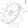
- the control system 1 comprises a sleeve 8, which is designed to be attached to the container 4, is fitted around the mouth 5, has a longitudinal axis 9, and protrudes axially from the cap 6.
- the control system 1 further has a guide disc 10 comprising a ring-shaped support plate 11 provided with an inner membrane 12, which is attached to the inside of the plate 11, is made of an elastically deformable material, and has a central hole 13.
- the hole 13 is designed to be engaged by the member 7, and has a diameter, which is smaller than a diameter of the cap 6, and approximates by excess the diameter of the member 7.
- the plate 11 is hinged to the sleeve 8 so as to rotate, with respect to the sleeve 8, around a fulcrum axis 14 parallel to the axis 9 between a first position ( Figures 1 and 2 ), in which the hole 13 is arranged coaxially to the axis 9 so as to allow the member 7 to feed fuel into the container 4 through the mouth 5, and a second position ( Figure 3 ), in which the disc 10 is arranged so as to allow the removal of the cap 6 from the mouth 5 and the application of the cap 6 on the mouth 5.
- the control system 1 further comprises a first detection device 15 for detecting whether the cap 6 is present or not on the mouth 5; a second detection device 16 for detecting whether the disc 10 is arranged in its first position; and a third detection device 17 for detecting whether the member 7 engages or disengages the mouth 5.
- the device 15 comprises, in this case, an RFID tag 18 mounted on the cap 6, a ring-shaped antenna 19 mounted on an inner surface of the sleeve 8 coaxially to axis 9, and an RFID reader 20 connected to the antenna 19 and configured to detect the presence of the RFID tag 18 through the antenna 19.
- the device 16 comprises, in this case, an RFID tag 21 mounted on the disc 10, a ring-shaped antenna 22 mounted on the inner surface of the sleeve 8 coaxially to the axis 9, and the RFID reader 20, which is connected to the antenna 22, and is configured to detect the presence of the RFID tag 21 through the antenna 22.
- the device 17 comprises, in this case, an RFID tag 23 mounted on the member 7 and the RFID reader 20, which is configured to detect the presence of the RFID tag 23 through the antenna 19 in order to detect when the member 7 engages the mouth 5 and through the antenna 22 in order to detect when the member 7 disengages the mouth 5.
- the control system 1 is further provided with a control device 24, which communicates with the RFID reader 20, and is configured to enable the delivery of fuel from the member 7 to the tank 3 when the device 15 detects that the cap 6 is not present on the mouth 5, the device 16 detects that the disc 10 is arranged in the first position, and the device 17 detects that the member 7 engages the mouth 5.
- a control device 24 which communicates with the RFID reader 20, and is configured to enable the delivery of fuel from the member 7 to the tank 3 when the device 15 detects that the cap 6 is not present on the mouth 5, the device 16 detects that the disc 10 is arranged in the first position, and the device 17 detects that the member 7 engages the mouth 5.
- the control device 24 is further configured to enable the delivery of fuel from the member 7 to the tank 3 when the amount of time elapsing between the detection of the RFID tag 21 through the antenna 22 and the detection of the RFID tag 23 through the antenna 19 is equal, at the most, to a given first threshold value.
- the device 24 enables the delivery of fuel at the beginning of the filling only when the user, once moved the disc 10 from the second position into the first position, inserts the member 7 in the mouth 5 within a given amount of time.
- the control device 24 is further configured to enable the delivery of fuel from the member 7 to the tank 3 when the amount of time elapsing between the detection of the RFID tag 23 through the antenna 22 and the detection of the RFID tag 23 through the antenna 19 is equal, at the most, to a given second threshold value.
- the device 24 does not interrupt the delivery of fuel during the filling only when the user, once extracted the member 7 from the mouth 5, reinserts the member 7 in the mouth 5 within a given amount of time.
- the disc 10 Once carried out the delivery of fuel and extracted the member 7 from the mouth 5, the disc 10 must be moved back into its second position and the cap 6 must be reapplied on the mouth 5 within a relatively reduced amount of time so as to prevent the access to the tank 3 and the fraudulent removal of fuel from the tank 3.
- control device 24 comprises a control unit 25 associated with the station 2, first wireless communication means (not illustrated) connected to the RFID reader 20, and second wireless communication means (not illustrated) connected to the control unit 25 and designed to communicate with the first wireless communication means (not illustrated).
- the control system 1 has some advantages mainly deriving from the fact that the diameter of the central hole 13 of the guide disc 10 allows inserting in the mouth 5 only the member 7 preventing the insertion of further pipes and that the detection devices 15, 16, 17 ensure the insertion in the mouth 5 only of the member 7 and not of pipes different from the member 7.
- the plate 27 is mounted so as to rotate around the axis 14 between a closed position ( Figure 4 ), in which the plate 27 is arranged coaxially to the axis 9 so as to prevent the access to the tank 3, and an open position (not illustrated), in which the plate 27 is arranged so as to allow the access to the tank 3.
- the plate 27 is provided with a tag 28, the presence thereof is detected through the antenna 22.
- the control device 26 communicates with the RFID reader 20, and is configured to enable the delivery of fuel from the member 7 to the tank 3 when the device 16 detects that the disc 10 is arranged in the first position, the device 17 detects that the member 7 engages the mouth 5, and the antenna 22 detects that the plate 27 is arranged in its open position.
- the plate 27 Once carried out the delivery of fuel and extracted the member 7 from the mouth 5, the plate 27 must be moved back into its closed position within a relatively reduced amount of time so as to prevent the access to the tank 3 and the fraudulent removal of fuel from the tank 3.
- the membrane 12 of the disc 10 is eliminated and replaced with a substantially truncated cone-shaped membrane made of elastically deformable material and provided with coupling means, for example magnets, to the member 7.
Landscapes
- Engineering & Computer Science (AREA)
- Mechanical Engineering (AREA)
- Life Sciences & Earth Sciences (AREA)
- Sustainable Development (AREA)
- Sustainable Energy (AREA)
- Chemical & Material Sciences (AREA)
- Combustion & Propulsion (AREA)
- Transportation (AREA)
- Cooling, Air Intake And Gas Exhaust, And Fuel Tank Arrangements In Propulsion Units (AREA)
- Closures For Containers (AREA)
- Loading And Unloading Of Fuel Tanks Or Ships (AREA)
- Filling Or Discharging Of Gas Storage Vessels (AREA)
Description
- This patent application claims priority from
Italian patent application no. 102019000019792 filed on 25/10/2019 - The present invention relates to a system for controlling the delivery of fuel from a dispenser device, in particular a filling station, to a storage container, in particular a tank of a vehicle.
- The present invention has particularly advantageous application in a system for controlling the delivery of fuel from a filling station to a tank of a vehicle, to which the following discussion will refer explicitly without thereby losing its generality.
- In the field of the delivery of fuel from a filling station to a tank of a vehicle, it is known to have a control system comprising an antenna mounted on a mouth of the tank; an RFID tag mounted on a delivering member of the filling station; an RFID reader connected to the antenna and configured to detect the presence of the RFID tag through the antenna; and a control unit associated with the filling station and configured to enable the delivery of fuel from the delivering member to the tank when the antenna detects the presence of the RFID tag.
- The known systems of the type described above for controlling the delivery of fuel from a filling station to a tank of a vehicle have some drawbacks mainly deriving from the fact that, once removed the closing cap of the mouth of the tank, the assembly defined by the RFID tag and by the antenna is incapable of ensuring that only the delivering member is inserted inside the tank and not also a pipe for the fraudulent removal of fuel simultaneously to the filling operation being conducted by means of the delivering member.
CN 105 857 060 B discloses a system to control the delivery of fuel according to the preamble of claim 1. - The object of the present invention is to provide a system for controlling the delivery of fuel from a dispenser device, in particular a filling station, to a storage container, in particular a tank of a vehicle, which is free from the drawbacks described above and which is simple and cost-effective to implement.
- According to the present invention, a system for controlling the delivery of fuel from a dispenser device, in particular a filling station, to a storage container, in particular a tank of a vehicle is provided, as claimed in the appended claims.
- The present invention will now be described with reference to the accompanying drawings, which illustrate a non-limiting embodiment example thereof, wherein:
-
Figure 1 shows a schematic lateral view, with parts in section and parts removed for clarity, of a preferred embodiment of the control system of the present invention; -
Figures 2 and3 show two perspective views of a detail of the control system ofFigure 1 illustrated in two different operating positions; and -
Figure 4 shows a schematic lateral view, with parts in section and parts removed for clarity, of a variant of the control system ofFigure 1 . - With reference to
Figures 1 ,2 , and3 , reference numeral 1 indicates, as a whole, a system for controlling the delivery of fuel from afilling station 2 to atank 3 of a vehicle (not illustrated). - The
tank 3 comprises acontainer 4 provided with afeeding mouth 5, and aclosing cap 6 mounted on themouth 5 for closing thecontainer 4. - The
station 2 comprises at least one filling pump (not illustrated) provided with a delivering member 7. - The control system 1 comprises a
sleeve 8, which is designed to be attached to thecontainer 4, is fitted around themouth 5, has alongitudinal axis 9, and protrudes axially from thecap 6. - The control system 1 further has a
guide disc 10 comprising a ring-shaped support plate 11 provided with aninner membrane 12, which is attached to the inside of theplate 11, is made of an elastically deformable material, and has acentral hole 13. - The
hole 13 is designed to be engaged by the member 7, and has a diameter, which is smaller than a diameter of thecap 6, and approximates by excess the diameter of the member 7. - The
plate 11 is hinged to thesleeve 8 so as to rotate, with respect to thesleeve 8, around afulcrum axis 14 parallel to theaxis 9 between a first position (Figures 1 and2 ), in which thehole 13 is arranged coaxially to theaxis 9 so as to allow the member 7 to feed fuel into thecontainer 4 through themouth 5, and a second position (Figure 3 ), in which thedisc 10 is arranged so as to allow the removal of thecap 6 from themouth 5 and the application of thecap 6 on themouth 5. - The control system 1 further comprises a
first detection device 15 for detecting whether thecap 6 is present or not on themouth 5; asecond detection device 16 for detecting whether thedisc 10 is arranged in its first position; and athird detection device 17 for detecting whether the member 7 engages or disengages themouth 5. - The
device 15 comprises, in this case, anRFID tag 18 mounted on thecap 6, a ring-shaped antenna 19 mounted on an inner surface of thesleeve 8 coaxially toaxis 9, and anRFID reader 20 connected to theantenna 19 and configured to detect the presence of theRFID tag 18 through theantenna 19. - The
device 16 comprises, in this case, anRFID tag 21 mounted on thedisc 10, a ring-shaped antenna 22 mounted on the inner surface of thesleeve 8 coaxially to theaxis 9, and theRFID reader 20, which is connected to theantenna 22, and is configured to detect the presence of theRFID tag 21 through theantenna 22. - The
device 17 comprises, in this case, anRFID tag 23 mounted on the member 7 and theRFID reader 20, which is configured to detect the presence of theRFID tag 23 through theantenna 19 in order to detect when the member 7 engages themouth 5 and through theantenna 22 in order to detect when the member 7 disengages themouth 5. - The control system 1 is further provided with a
control device 24, which communicates with theRFID reader 20, and is configured to enable the delivery of fuel from the member 7 to thetank 3 when thedevice 15 detects that thecap 6 is not present on themouth 5, thedevice 16 detects that thedisc 10 is arranged in the first position, and thedevice 17 detects that the member 7 engages themouth 5. - The
control device 24 is further configured to enable the delivery of fuel from the member 7 to thetank 3 when the amount of time elapsing between the detection of theRFID tag 21 through theantenna 22 and the detection of theRFID tag 23 through theantenna 19 is equal, at the most, to a given first threshold value. - In other words, the
device 24 enables the delivery of fuel at the beginning of the filling only when the user, once moved thedisc 10 from the second position into the first position, inserts the member 7 in themouth 5 within a given amount of time. - The
control device 24 is further configured to enable the delivery of fuel from the member 7 to thetank 3 when the amount of time elapsing between the detection of theRFID tag 23 through theantenna 22 and the detection of theRFID tag 23 through theantenna 19 is equal, at the most, to a given second threshold value. - In other words, the
device 24 does not interrupt the delivery of fuel during the filling only when the user, once extracted the member 7 from themouth 5, reinserts the member 7 in themouth 5 within a given amount of time. - Once carried out the delivery of fuel and extracted the member 7 from the
mouth 5, thedisc 10 must be moved back into its second position and thecap 6 must be reapplied on themouth 5 within a relatively reduced amount of time so as to prevent the access to thetank 3 and the fraudulent removal of fuel from thetank 3. - With regard to what presented above, it should be specified that the
control device 24 comprises acontrol unit 25 associated with thestation 2, first wireless communication means (not illustrated) connected to theRFID reader 20, and second wireless communication means (not illustrated) connected to thecontrol unit 25 and designed to communicate with the first wireless communication means (not illustrated). - The control system 1 has some advantages mainly deriving from the fact that the diameter of the
central hole 13 of theguide disc 10 allows inserting in themouth 5 only the member 7 preventing the insertion of further pipes and that thedetection devices mouth 5 only of the member 7 and not of pipes different from the member 7. - The variant illustrated in
Figure 4 differs from what illustrated in the previous figures for the fact that, therein: - the
tag 18 of thecap 6 is eliminated; - the
control device 24 is eliminated and replaced with acontrol device 26; and - on top the disc 10 a
circular plate 27 is mounted. - The
plate 27 is mounted so as to rotate around theaxis 14 between a closed position (Figure 4 ), in which theplate 27 is arranged coaxially to theaxis 9 so as to prevent the access to thetank 3, and an open position (not illustrated), in which theplate 27 is arranged so as to allow the access to thetank 3. - The
plate 27 is provided with atag 28, the presence thereof is detected through theantenna 22. - The
control device 26 communicates with theRFID reader 20, and is configured to enable the delivery of fuel from the member 7 to thetank 3 when thedevice 16 detects that thedisc 10 is arranged in the first position, thedevice 17 detects that the member 7 engages themouth 5, and theantenna 22 detects that theplate 27 is arranged in its open position. - Once carried out the delivery of fuel and extracted the member 7 from the
mouth 5, theplate 27 must be moved back into its closed position within a relatively reduced amount of time so as to prevent the access to thetank 3 and the fraudulent removal of fuel from thetank 3. - According to a variant not illustrated, the
membrane 12 of thedisc 10 is eliminated and replaced with a substantially truncated cone-shaped membrane made of elastically deformable material and provided with coupling means, for example magnets, to the member 7.
Claims (15)
- A system to control the delivery of fuel from a dispenser device (2), in particular a filling station, to a storage container (3), in particular a tank of a vehicle, characterised in that the control system comprises a sleeve (8) designed to be fitted around a closing cap (6) of a mouth (5) of the storage container (3); a guide disc (10), which has a central hole (13) able to be engaged by a delivering member (7) of the dispenser device (2), and is coupled to the sleeve (8) so as to move between a first position, in which the guide disc (10) allows the delivering member (7) to feed fuel into the storage container (3) through the mouth (5), and a second position, in which the closing cap (6) is removable from the mouth (5); first detection means (16) to detect whether the guide disc (10) is arranged in its first position; second detection means (17) to detect whether the delivering member (7) engages or disengages the mouth (5); and control means (24) configured to enable the delivery of fuel from the dispenser device (2) to the storage container (3) when the first detection means (16) detect that the guide disc (10) is arranged in the first position and the second detection means (17) detect that the delivering member (7) engages the mouth (5).
- A control system according to claim 1, wherein the first detection means (16) comprise a first RFID tag (21) mounted on the guide disc (10), a first antenna (22) mounted on the sleeve (8), and an RFID reader (20), which is connected to the first antenna (22), and is configured to detect the presence of the first RFID tag (21) through the first antenna (22) and to communicate with the control means (24).
- A control system according to claim 2, wherein the second detection means (17) comprise a second RFID tag (23) mounted on the delivering member (7), a second antenna (19) mounted on the sleeve (8), and said RFID reader (20), which is configured to detect the presence of the second RFID tag (23) through the second antenna (19) in order to detect when the delivering member (7) engages the mouth (5).
- A control system according to claim 3, wherein the control means (24) are configured to enable the delivery of fuel from the dispenser device (2) to the storage container (3) when the amount of time elapsing between the detection of the first RFID tag (21) through the first antenna (22) and the detection of the second RFID tag (23) through the second antenna (19) is equal, at the most, to a given first threshold value.
- A control system according to claim 2, wherein the second detection means (17) comprise a second RFID tag (23) mounted on the delivering member (7), a second antenna (19) mounted on the sleeve (8), and said RFID reader (20), which is configured to detect the presence of the second RFID tag (23) through the first antenna (22) in order to detect when the delivering member (7) disengages the mouth (5).
- A control system according to claim 5, wherein the control means (24) are configured to enable the delivery of fuel from the dispenser device (2) to the storage container (3) when the amount of time elapsing between the detection of the second RFID tag (23) through the first antenna (22) and the detection of the second RFID tag (23) through the second antenna (19) is equal, at the most, to a given second threshold value.
- A control system according to any one of the claims from 3 to 6 and further comprising third detection means (15) to detect whether the closing cap (6) is present or not on the mouth (5).
- A control system according to claim 7, wherein the control means (24) are configured to enable the delivery of fuel from the dispenser device (2) to the storage container (3) when the third detection means (15) detect that the closing cap (6) is not present on the mouth (5).
- A control system according to claim 7 or 8, wherein the third detection means (15) comprise a third RFID tag (18) mounted on the closing cap (6) and said RFID reader (20), which is configured to detect the presence of the third RFID tag (18) through the second antenna (19) in order to detect when the closing cap (6) is present on the mouth (5).
- A control system according to any one of the claims from 3 to 6 and further comprising a closing plate (27); the guide disc (10) being mounted between the sleeve (8) and the closing plate (27).
- A control system according to claim 10, wherein the closing plate (27) is movable between a closed position, in which the closing plate (27) forbids access to the guide disc (10) and, hence, to the storage container (3), and an open position, in which the closing plate (27) allows access to the guide disc (10) and, hence, to the storage container (3).
- A control system according to claim 11 and further comprising a fourth RFID tag (28) mounted on the closing plate (27); the RFID reader (20) being configured to detect the presence of the fourth RFID tag (28) through the first antenna (22) in order to detect when the closing plate (27) is arranged in its closed position or in its open position.
- A control system according to any one of the claims from 2 to 12, wherein the control means (24) comprise a control unit (25) associated with the dispenser device (2), first wireless communication means connected to the RFID reader (20), and second wireless communication means connected to the control unit (25) and designed to communicate with the first wireless communication means.
- A control system according to any one of the preceding claims, wherein the guide disc (10) comprises an elastically deformable membrane (12) provided with the central hole (13).
- A control system according to any one of the preceding claims, wherein the central hole (13) of the guide disc (10) has a smaller diameter than a diameter of the closing cap (6) of the mouth (5) of the storage container (3).
Priority Applications (2)
| Application Number | Priority Date | Filing Date | Title |
|---|---|---|---|
| RS20220702A RS63516B1 (en) | 2019-10-25 | 2020-10-23 | SYSTEM FOR CONTROLLING THE DISPENSING OF FUEL FROM A DISPENSING DEVICE, IN PARTICULAR A PETROL STATION, INTO A STORAGE CONTAINER, IN PARTICULAR A VEHICLE TANK |
| HRP20220977TT HRP20220977T1 (en) | 2019-10-25 | 2020-10-23 | System to control the delivery of fuel from a dispenser device, in particular a filling station, to a storage container, in particular a tank of a vehicle |
Applications Claiming Priority (1)
| Application Number | Priority Date | Filing Date | Title |
|---|---|---|---|
| IT102019000019792A IT201900019792A1 (en) | 2019-10-25 | 2019-10-25 | SYSTEM FOR CONTROL OF FUEL DELIVERY FROM A DISTRIBUTION DEVICE, IN PARTICULAR A FILLING STATION, TO A STORAGE CONTAINER, IN PARTICULAR A TANK OF A VEHICLE |
Publications (2)
| Publication Number | Publication Date |
|---|---|
| EP3819152A1 EP3819152A1 (en) | 2021-05-12 |
| EP3819152B1 true EP3819152B1 (en) | 2022-06-29 |
Family
ID=69811546
Family Applications (1)
| Application Number | Title | Priority Date | Filing Date |
|---|---|---|---|
| EP20203674.5A Active EP3819152B1 (en) | 2019-10-25 | 2020-10-23 | System to control the delivery of fuel from a dispenser device, in particular a filling station, to a storage container, in particular a tank of a vehicle |
Country Status (8)
| Country | Link |
|---|---|
| EP (1) | EP3819152B1 (en) |
| ES (1) | ES2924372T3 (en) |
| HR (1) | HRP20220977T1 (en) |
| HU (1) | HUE059862T2 (en) |
| IT (1) | IT201900019792A1 (en) |
| LT (1) | LT3819152T (en) |
| PL (1) | PL3819152T3 (en) |
| RS (1) | RS63516B1 (en) |
Family Cites Families (5)
| Publication number | Priority date | Publication date | Assignee | Title |
|---|---|---|---|---|
| WO2005025913A1 (en) * | 2003-09-12 | 2005-03-24 | Inergy Automotive Systems Research | Closure for fuel-tank filler pipe |
| ITPD20090299A1 (en) * | 2009-10-15 | 2011-04-16 | Tibb S R L | NOZZLE, PARTICULARLY FOR FUEL TANKS FOR VEHICLES AND THE LIKE |
| DE102010008206A1 (en) * | 2010-02-17 | 2011-08-18 | Daimler AG, 70327 | Tank device for a fuel tank of a fuel cell vehicle and tank system |
| PT2778116T (en) * | 2013-03-15 | 2019-08-23 | Itcico Spain S L | Apparatus and method for transferring data between a fuel providing means and a vehicle for the prevention of misfuelling |
| CN105857060B (en) * | 2016-04-08 | 2019-03-01 | 重庆先锋渝州电器有限公司 | A kind of automobile fuel filler port lid occlusion detection system |
-
2019
- 2019-10-25 IT IT102019000019792A patent/IT201900019792A1/en unknown
-
2020
- 2020-10-23 HU HUE20203674A patent/HUE059862T2/en unknown
- 2020-10-23 ES ES20203674T patent/ES2924372T3/en active Active
- 2020-10-23 HR HRP20220977TT patent/HRP20220977T1/en unknown
- 2020-10-23 RS RS20220702A patent/RS63516B1/en unknown
- 2020-10-23 EP EP20203674.5A patent/EP3819152B1/en active Active
- 2020-10-23 PL PL20203674.5T patent/PL3819152T3/en unknown
- 2020-10-23 LT LTEP20203674.5T patent/LT3819152T/en unknown
Also Published As
| Publication number | Publication date |
|---|---|
| RS63516B1 (en) | 2022-09-30 |
| PL3819152T3 (en) | 2022-11-21 |
| HRP20220977T1 (en) | 2022-11-11 |
| HUE059862T2 (en) | 2023-01-28 |
| IT201900019792A1 (en) | 2021-04-25 |
| ES2924372T3 (en) | 2022-10-06 |
| LT3819152T (en) | 2022-08-10 |
| EP3819152A1 (en) | 2021-05-12 |
Similar Documents
| Publication | Publication Date | Title |
|---|---|---|
| US11161729B2 (en) | Empty keg detection for carbonated beverages | |
| EP2672328B1 (en) | Device for automatically supplying toner to toner cartridge | |
| EP3177532B1 (en) | Filler neck closure assembly | |
| EP3380355B1 (en) | Solenoid assembly for a valve | |
| US12286338B2 (en) | Method for supplying a mobile usage unit with a consumable | |
| EP2778116A1 (en) | Apparatus and method for transferring data between a fuel providing means and a vehicle for the prevention of misfuelling | |
| US20150068623A1 (en) | Removal System | |
| EP2632845B1 (en) | Dispensing appliance provided with means for positionning a container | |
| JP2022507638A5 (en) | ||
| US9809438B2 (en) | Fluid dispensing apparatus and system | |
| KR20180087593A (en) | Solenoid valve including pilot plunger head which is moving independently from the pilot plunger | |
| ZA202109642B (en) | A fuel container | |
| EP3819152B1 (en) | System to control the delivery of fuel from a dispenser device, in particular a filling station, to a storage container, in particular a tank of a vehicle | |
| EP3340758A2 (en) | Portion-wise filling of a reservoir with bulk components | |
| CN105402420A (en) | Filling limiting cylinder valve | |
| EP2369307A1 (en) | Automatic liquid dispensing gun | |
| US11649079B2 (en) | Method and apparatus for refilling a container | |
| US11613455B1 (en) | Automated venting of gas/foam from foam on beer detector for carbonated beverages | |
| EP3640197B1 (en) | Filling machine for hot filling | |
| EP1502749A1 (en) | Inkjet recording apparatus and ink cartridge | |
| JP6253471B2 (en) | Joining device for inkjet printer | |
| ITMI990484V0 (en) | APPARATUS FOR DISPENSING A STAINING FLUID FOR AUTOMATIC BANKNOTE AND VALUE DISPENSING MACHINES | |
| CN210190509U (en) | Material receiver with material level detection device | |
| US11673787B1 (en) | Empty keg detection for carbonated beverages | |
| KR102558486B1 (en) | Aseptic and quantitative fluid ejecting device, and Squeeze bottle product having the same |
Legal Events
| Date | Code | Title | Description |
|---|---|---|---|
| REG | Reference to a national code |
Ref country code: HR Ref legal event code: TUEP Ref document number: P20220977T Country of ref document: HR |
|
| PUAI | Public reference made under article 153(3) epc to a published international application that has entered the european phase |
Free format text: ORIGINAL CODE: 0009012 |
|
| STAA | Information on the status of an ep patent application or granted ep patent |
Free format text: STATUS: THE APPLICATION HAS BEEN PUBLISHED |
|
| AK | Designated contracting states |
Kind code of ref document: A1 Designated state(s): AL AT BE BG CH CY CZ DE DK EE ES FI FR GB GR HR HU IE IS IT LI LT LU LV MC MK MT NL NO PL PT RO RS SE SI SK SM TR |
|
| STAA | Information on the status of an ep patent application or granted ep patent |
Free format text: STATUS: REQUEST FOR EXAMINATION WAS MADE |
|
| 17P | Request for examination filed |
Effective date: 20211104 |
|
| RBV | Designated contracting states (corrected) |
Designated state(s): AL AT BE BG CH CY CZ DE DK EE ES FI FR GB GR HR HU IE IS IT LI LT LU LV MC MK MT NL NO PL PT RO RS SE SI SK SM TR |
|
| GRAP | Despatch of communication of intention to grant a patent |
Free format text: ORIGINAL CODE: EPIDOSNIGR1 |
|
| STAA | Information on the status of an ep patent application or granted ep patent |
Free format text: STATUS: GRANT OF PATENT IS INTENDED |
|
| INTG | Intention to grant announced |
Effective date: 20220118 |
|
| GRAS | Grant fee paid |
Free format text: ORIGINAL CODE: EPIDOSNIGR3 |
|
| GRAA | (expected) grant |
Free format text: ORIGINAL CODE: 0009210 |
|
| STAA | Information on the status of an ep patent application or granted ep patent |
Free format text: STATUS: THE PATENT HAS BEEN GRANTED |
|
| AK | Designated contracting states |
Kind code of ref document: B1 Designated state(s): AL AT BE BG CH CY CZ DE DK EE ES FI FR GB GR HR HU IE IS IT LI LT LU LV MC MK MT NL NO PL PT RO RS SE SI SK SM TR |
|
| REG | Reference to a national code |
Ref country code: CH Ref legal event code: EP |
|
| REG | Reference to a national code |
Ref country code: AT Ref legal event code: REF Ref document number: 1501115 Country of ref document: AT Kind code of ref document: T Effective date: 20220715 |
|
| REG | Reference to a national code |
Ref country code: IE Ref legal event code: FG4D |
|
| REG | Reference to a national code |
Ref country code: DE Ref legal event code: R096 Ref document number: 602020003766 Country of ref document: DE |
|
| REG | Reference to a national code |
Ref country code: RO Ref legal event code: EPE |
|
| REG | Reference to a national code |
Ref country code: FI Ref legal event code: FGE Ref country code: NL Ref legal event code: FP |
|
| REG | Reference to a national code |
Ref country code: SE Ref legal event code: TRGR |
|
| REG | Reference to a national code |
Ref country code: ES Ref legal event code: FG2A Ref document number: 2924372 Country of ref document: ES Kind code of ref document: T3 Effective date: 20221006 |
|
| REG | Reference to a national code |
Ref country code: GR Ref legal event code: EP Ref document number: 20220401608 Country of ref document: GR Effective date: 20221010 |
|
| PG25 | Lapsed in a contracting state [announced via postgrant information from national office to epo] |
Ref country code: NO Free format text: LAPSE BECAUSE OF FAILURE TO SUBMIT A TRANSLATION OF THE DESCRIPTION OR TO PAY THE FEE WITHIN THE PRESCRIBED TIME-LIMIT Effective date: 20220929 |
|
| REG | Reference to a national code |
Ref country code: HR Ref legal event code: T1PR Ref document number: P20220977 Country of ref document: HR |
|
| REG | Reference to a national code |
Ref country code: SK Ref legal event code: T3 Ref document number: E 40527 Country of ref document: SK |
|
| REG | Reference to a national code |
Ref country code: HR Ref legal event code: ODRP Ref document number: P20220977 Country of ref document: HR Payment date: 20221005 Year of fee payment: 3 |
|
| REG | Reference to a national code |
Ref country code: HU Ref legal event code: AG4A Ref document number: E059862 Country of ref document: HU |
|
| PG25 | Lapsed in a contracting state [announced via postgrant information from national office to epo] |
Ref country code: SM Free format text: LAPSE BECAUSE OF FAILURE TO SUBMIT A TRANSLATION OF THE DESCRIPTION OR TO PAY THE FEE WITHIN THE PRESCRIBED TIME-LIMIT Effective date: 20220629 Ref country code: PT Free format text: LAPSE BECAUSE OF FAILURE TO SUBMIT A TRANSLATION OF THE DESCRIPTION OR TO PAY THE FEE WITHIN THE PRESCRIBED TIME-LIMIT Effective date: 20221031 Ref country code: EE Free format text: LAPSE BECAUSE OF FAILURE TO SUBMIT A TRANSLATION OF THE DESCRIPTION OR TO PAY THE FEE WITHIN THE PRESCRIBED TIME-LIMIT Effective date: 20220629 |
|
| PG25 | Lapsed in a contracting state [announced via postgrant information from national office to epo] |
Ref country code: IS Free format text: LAPSE BECAUSE OF FAILURE TO SUBMIT A TRANSLATION OF THE DESCRIPTION OR TO PAY THE FEE WITHIN THE PRESCRIBED TIME-LIMIT Effective date: 20221029 |
|
| REG | Reference to a national code |
Ref country code: DE Ref legal event code: R097 Ref document number: 602020003766 Country of ref document: DE |
|
| PG25 | Lapsed in a contracting state [announced via postgrant information from national office to epo] |
Ref country code: AL Free format text: LAPSE BECAUSE OF FAILURE TO SUBMIT A TRANSLATION OF THE DESCRIPTION OR TO PAY THE FEE WITHIN THE PRESCRIBED TIME-LIMIT Effective date: 20220629 |
|
| PG25 | Lapsed in a contracting state [announced via postgrant information from national office to epo] |
Ref country code: DK Free format text: LAPSE BECAUSE OF FAILURE TO SUBMIT A TRANSLATION OF THE DESCRIPTION OR TO PAY THE FEE WITHIN THE PRESCRIBED TIME-LIMIT Effective date: 20220629 |
|
| PLBE | No opposition filed within time limit |
Free format text: ORIGINAL CODE: 0009261 |
|
| STAA | Information on the status of an ep patent application or granted ep patent |
Free format text: STATUS: NO OPPOSITION FILED WITHIN TIME LIMIT |
|
| PG25 | Lapsed in a contracting state [announced via postgrant information from national office to epo] |
Ref country code: MC Free format text: LAPSE BECAUSE OF FAILURE TO SUBMIT A TRANSLATION OF THE DESCRIPTION OR TO PAY THE FEE WITHIN THE PRESCRIBED TIME-LIMIT Effective date: 20220629 |
|
| 26N | No opposition filed |
Effective date: 20230330 |
|
| PG25 | Lapsed in a contracting state [announced via postgrant information from national office to epo] |
Ref country code: LU Free format text: LAPSE BECAUSE OF NON-PAYMENT OF DUE FEES Effective date: 20221023 |
|
| P01 | Opt-out of the competence of the unified patent court (upc) registered |
Effective date: 20230601 |
|
| PG25 | Lapsed in a contracting state [announced via postgrant information from national office to epo] |
Ref country code: SI Free format text: LAPSE BECAUSE OF FAILURE TO SUBMIT A TRANSLATION OF THE DESCRIPTION OR TO PAY THE FEE WITHIN THE PRESCRIBED TIME-LIMIT Effective date: 20220629 |
|
| REG | Reference to a national code |
Ref country code: HR Ref legal event code: ODRP Ref document number: P20220977 Country of ref document: HR Payment date: 20231018 Year of fee payment: 4 |
|
| PG25 | Lapsed in a contracting state [announced via postgrant information from national office to epo] |
Ref country code: IE Free format text: LAPSE BECAUSE OF NON-PAYMENT OF DUE FEES Effective date: 20221023 |
|
| PG25 | Lapsed in a contracting state [announced via postgrant information from national office to epo] |
Ref country code: CY Free format text: LAPSE BECAUSE OF FAILURE TO SUBMIT A TRANSLATION OF THE DESCRIPTION OR TO PAY THE FEE WITHIN THE PRESCRIBED TIME-LIMIT Effective date: 20220629 |
|
| PG25 | Lapsed in a contracting state [announced via postgrant information from national office to epo] |
Ref country code: MK Free format text: LAPSE BECAUSE OF FAILURE TO SUBMIT A TRANSLATION OF THE DESCRIPTION OR TO PAY THE FEE WITHIN THE PRESCRIBED TIME-LIMIT Effective date: 20220629 |
|
| PG25 | Lapsed in a contracting state [announced via postgrant information from national office to epo] |
Ref country code: AL Free format text: LAPSE BECAUSE OF FAILURE TO SUBMIT A TRANSLATION OF THE DESCRIPTION OR TO PAY THE FEE WITHIN THE PRESCRIBED TIME-LIMIT Effective date: 20220629 |
|
| PGRI | Patent reinstated in contracting state [announced from national office to epo] |
Ref country code: AL Effective date: 20220725 |
|
| REG | Reference to a national code |
Ref country code: AT Ref legal event code: UEP Ref document number: 1501115 Country of ref document: AT Kind code of ref document: T Effective date: 20220629 |
|
| PG25 | Lapsed in a contracting state [announced via postgrant information from national office to epo] |
Ref country code: MT Free format text: LAPSE BECAUSE OF FAILURE TO SUBMIT A TRANSLATION OF THE DESCRIPTION OR TO PAY THE FEE WITHIN THE PRESCRIBED TIME-LIMIT Effective date: 20220629 |
|
| REG | Reference to a national code |
Ref country code: HR Ref legal event code: ODRP Ref document number: P20220977 Country of ref document: HR Payment date: 20241004 Year of fee payment: 5 |
|
| PGFP | Annual fee paid to national office [announced via postgrant information from national office to epo] |
Ref country code: PL Payment date: 20250929 Year of fee payment: 6 |
|
| REG | Reference to a national code |
Ref country code: HR Ref legal event code: ODRP Ref document number: P20220977 Country of ref document: HR Payment date: 20251002 Year of fee payment: 6 |
|
| REG | Reference to a national code |
Ref country code: CH Ref legal event code: U11 Free format text: ST27 STATUS EVENT CODE: U-0-0-U10-U11 (AS PROVIDED BY THE NATIONAL OFFICE) Effective date: 20251101 |
|
| PGFP | Annual fee paid to national office [announced via postgrant information from national office to epo] |
Ref country code: HU Payment date: 20251021 Year of fee payment: 6 |
|
| PGFP | Annual fee paid to national office [announced via postgrant information from national office to epo] |
Ref country code: NL Payment date: 20251024 Year of fee payment: 6 |
|
| PGFP | Annual fee paid to national office [announced via postgrant information from national office to epo] |
Ref country code: DE Payment date: 20251028 Year of fee payment: 6 |
|
| PGFP | Annual fee paid to national office [announced via postgrant information from national office to epo] |
Ref country code: LT Payment date: 20251003 Year of fee payment: 6 Ref country code: GB Payment date: 20251023 Year of fee payment: 6 |
|
| PGFP | Annual fee paid to national office [announced via postgrant information from national office to epo] |
Ref country code: AT Payment date: 20251020 Year of fee payment: 6 |
|
| PGFP | Annual fee paid to national office [announced via postgrant information from national office to epo] |
Ref country code: FI Payment date: 20251024 Year of fee payment: 6 Ref country code: IT Payment date: 20251007 Year of fee payment: 6 |
|
| PGFP | Annual fee paid to national office [announced via postgrant information from national office to epo] |
Ref country code: FR Payment date: 20251027 Year of fee payment: 6 Ref country code: HR Payment date: 20251002 Year of fee payment: 6 |
|
| PGFP | Annual fee paid to national office [announced via postgrant information from national office to epo] |
Ref country code: GR Payment date: 20251020 Year of fee payment: 6 Ref country code: BE Payment date: 20251024 Year of fee payment: 6 Ref country code: AL Payment date: 20251029 Year of fee payment: 6 Ref country code: TR Payment date: 20251002 Year of fee payment: 6 |
|
| PGFP | Annual fee paid to national office [announced via postgrant information from national office to epo] |
Ref country code: CH Payment date: 20251101 Year of fee payment: 6 Ref country code: SE Payment date: 20251024 Year of fee payment: 6 |
|
| PGFP | Annual fee paid to national office [announced via postgrant information from national office to epo] |
Ref country code: CZ Payment date: 20251014 Year of fee payment: 6 |
|
| PGFP | Annual fee paid to national office [announced via postgrant information from national office to epo] |
Ref country code: LV Payment date: 20251023 Year of fee payment: 6 |
|
| PGFP | Annual fee paid to national office [announced via postgrant information from national office to epo] |
Ref country code: BG Payment date: 20251028 Year of fee payment: 6 |
|
| PGFP | Annual fee paid to national office [announced via postgrant information from national office to epo] |
Ref country code: SK Payment date: 20251007 Year of fee payment: 6 Ref country code: RO Payment date: 20251016 Year of fee payment: 6 |
|
| PGFP | Annual fee paid to national office [announced via postgrant information from national office to epo] |
Ref country code: RS Payment date: 20251002 Year of fee payment: 6 |
|
| PGFP | Annual fee paid to national office [announced via postgrant information from national office to epo] |
Ref country code: ES Payment date: 20251118 Year of fee payment: 6 |